

Pentair P42B0005A1-01, P42B0007A2-01, P42B0015A2-01, P42B0010A2-01, P42B0005A1 Electronic Manual
...
®
pentek
ElEctroNics MaNual
inStallatiOn • OPeratiOn • MaintenanCe
WWW.pUMpS.COM

Table of Contents
SECTION 1: General Safety Guidelines
SECTION 2: Nomenclature
2.1 Motors
Driv
2.2
2.3
es
Submersibl
e Motor Controls
SECTION 3: Installation and Setup
3.1 General Installation Guidelines
Proper Gr
3.2
3.3
Corrosiv
Check Val
3.4
3.5
St
ounding
e Water and Ground
ves
art-Up
SECTION 4: Electrical Power
4.1 Mixing Wire Size with Existing Installation
Wire Splicing
4.2
4.3
3-Phase Start
Checking Motor R
4.4
4.5
3-Phase Current Balancing
Transformer Sizing
4.6
Using a Generat
4.7
4.8
Special Applications
ers
otation
or
SECTION 5: XE Series 4” SubmersibleMotors
5.1 Motor Inspection
5.2 Testing
5.3
5.4
5.5
5.6
5.7
5.8
5.9
5.10
age and Transportation
Stor
4” Motor Specific
4” Motor Dimensions
4” Motor Fuse Sizing
Cable Lengths
4” Motor Ov
Motor Cooling
Starting F
ations
erload Protection
requency
SECTION 6: Pentek® 6” Submersible Motors
6.1 Motor Inspection
6.2 Testing
6.3
6.4
6.5
6.6
6.7
6.8
6.9
6.10
6.11 Troubleshooting
age and Drain/Fill Instructions
Stor
Motor Specific
Motor Dimensions
Motor Fuse Sizing and Cable Selection
Overl
Motor Cooling
Head Loss In Casing
oad Protection
Starting F
ations
requency
SECTION 7: Hitachi® 6” Submersible Motors
7.1 Motor Inspection
7.2 Testing
7.3
7.4
7.5
7.6
7.7
7.8
7.9
7.10
7.11 Troubleshooting
age and Drain/Fill Instructions
Stor
Motor Specific
Motor Dimensions
Motor Fuse Sizing and Cable Selection
Overl
Motor Cooling
Head Loss In Casing
oad Protection
Starting F
ations
requency
SECTION 8: Pentek Intellidrive™ Variable
Frequency Drives
8.1 General Safety
Description
8.2
8.3
8.4
8.5
8.6 I/O Connections
8.7
8.8 Troubleshooting
8.9 Warranty
tallation
Ins
Initial Startup Pr
Advanc
Wiring Sizing, Repair P
ed Programming
ogrammingProcedure
arts, Specifications
SECTION 9: PPC Series 50/60 Hz Variable
Frequency Drives
9.1 Pentek PPC-Series Drives
PPC3 Series Specifications
9.2
9.3
PPC5 Series Specifications
Wiring Connections
9.4
9.5
ansducer Connection
Tr
9.6 Pentek Assistant
Timer Function
9.7
9.8
Helpful Hints
PPC3 and PPC5 Tank Sizing
9.9
9.10
React
ors And Filters
SECTION 10: PPX NEMA Pump Panels
10.1 Description
SECTION 11: Submersible Motor Controls
11.1 How it Works
Specific
11.2
11.3
Mounting and Inst
11.4
ations
allation
Wiring Connections and Replac
ement Parts
SECTION 12: Motor Protective Devices - 50/60 Hz
12.1 How They Work
Specific
12.2
12.3
Mounting And Inst
Wiring Connections
12.4
ations
allation
SECTION 13: Troubleshooting
13.1 Pump And Motor Problem Analysis
Motor T
13.2
13.3
Tes
13.4
13.5 Submersible Controls Troubleshooting
roubleshooting Flow Charts
ting Submersible Motor Insulation and Winding
Resistance
Smart Pump Prot
ector Troubleshooting
SECTION 14: Appendix
14.1 Installation Checklist
Choosing A Pump Sy
14.2
14.3
Sizing Submersibl
How t
14.4
14.5
14.6 Record of Installation
Hitachi® is a registered trademark of Hitachi Industrial Equipment Systems Co., Ltd.
All other brand or product names are trademarks or registered trademarks of Pentair Ltd.
o Select the Correct Pumping Equipment
Sizing Tank
s
stem
e Pump, Motor, and Tanks
© 2013 PN793 (08/20/13)
SECTION 1: General Safety Guidelines
Important Safety Instructions
SAVE THESE INSTRUCTIONS - This manual contains
important instructions that should be followed during
installation, operation, and maintenance of the product.
Always refer to the equipment owner’s manual for safety
information relevant to that product.
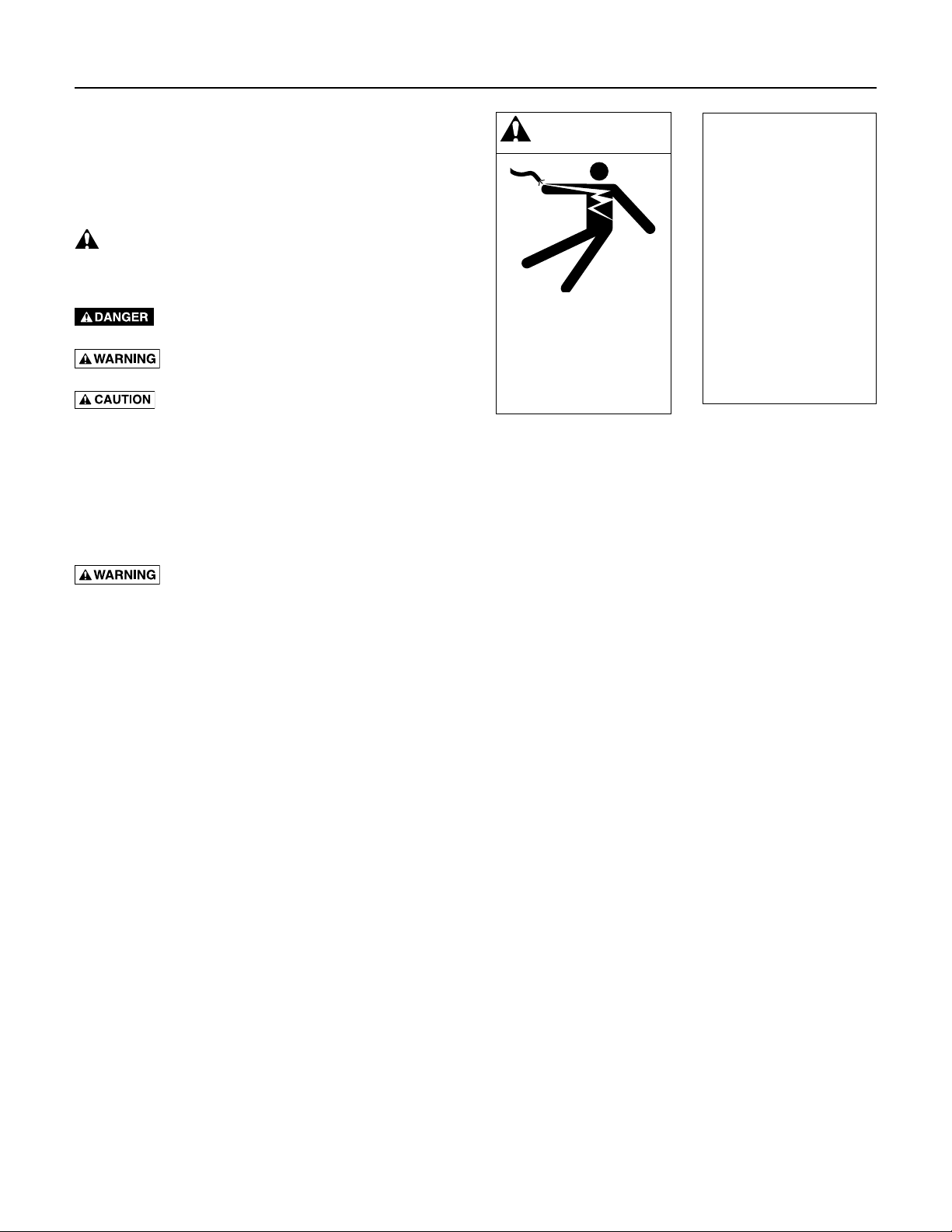
This is the safety alert symbol. When you see this
symbol on your product or in this manual, look for one of
the following signal words and be alert to the potential for
personal injury!
indicates a hazard which, if not avoided, will
result in death or serious injury.
indicates a hazard which, if not avoided,
could result in death or serious injury.
indicates a hazard which, if not avoided,
could result in minor or moderate injury.
NOTICE addresses practices not related to personal
injury.
Carefully read and follow all safety instructions in this
manual and on product.
Keep safety labels in good condition.
Replace missing or damaged safety labels.
Fatal Electrical Shock Hazard.
• Groundmotor,controls,allmetalpipeand
accessories connected to the motor, to the power
supply ground terminal. Ground wire must be at least
as large as motor supply cables.
• Disconnectpowerbeforeworkingonthesystem.
• Donotusethemotorinaswimmingarea.
WARNING
Hazardous voltage. Can
shock, burn, or cause death.
Ground pump before
connecting to power supply.
Disconnect power before
working on pump, motor
ortank.
All work
must be done
by a trained
and qualified
installer
or service
technician.
2
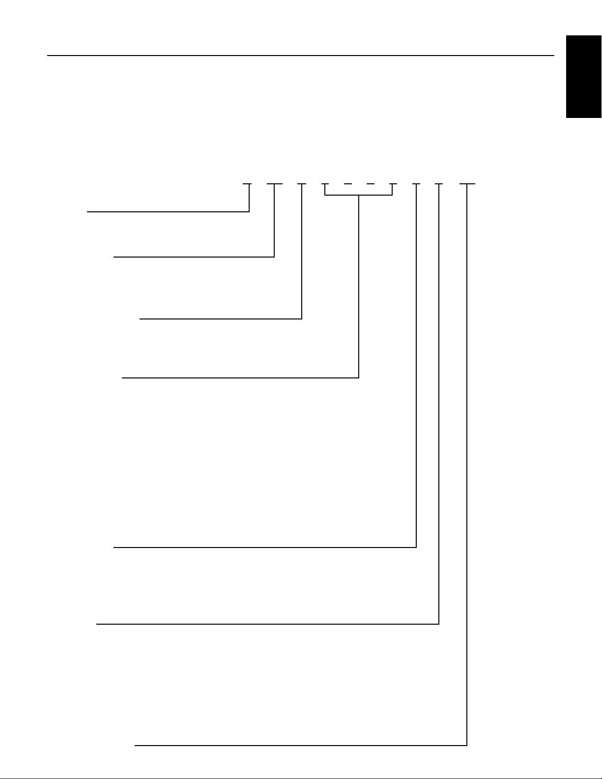
SECTION 2: Nomenclature
2.1 Motors
Table 2-1: Motor Nomenclature
Sample:
P43B0010A2-01 is a PENTEK 4” Stainless Steel Motor
1 HP, 60 Hz., 230 V, 1 Ph., Rev. 1
Nomenclature
Name Plate Example:
Brand
P = PENTEK
Motor Size
42 = 4 inch, 2-wire
43 = 4 inch, 3-wire
Motor Material
B = All stainless steel
S = CBM
Horsepower
0005 = 1/2 HP
0007 = 3/4 HP
0010 = 1 HP
0015 = 1-1/2 HP
0020 = 2 HP
0030 = 3 HP
0050 = 5 HP
0075 = 7-1/2 HP
0100 = 10 HP
P 43 B 0 0 1 0 A 2 -01
Frequency
A = 60 Hz.
B = 50 Hz.
C = 50/60 Hz.
Voltage
1 = 115 V, 1 Ph.
2 = 230 V, 1 Ph.
3 = 230 V, 3 Ph.
4 = 460 V, 3 Ph.
5 = 575 V, 3 Ph.
8 = 200 V, 3 Ph
Revision Code
3
SECTION 2: Nomenclature
Ser
SMC_(Std.
SMC5 (50 Hz)
SMC - CR 50 2 1
1 (Single)
PID – 10
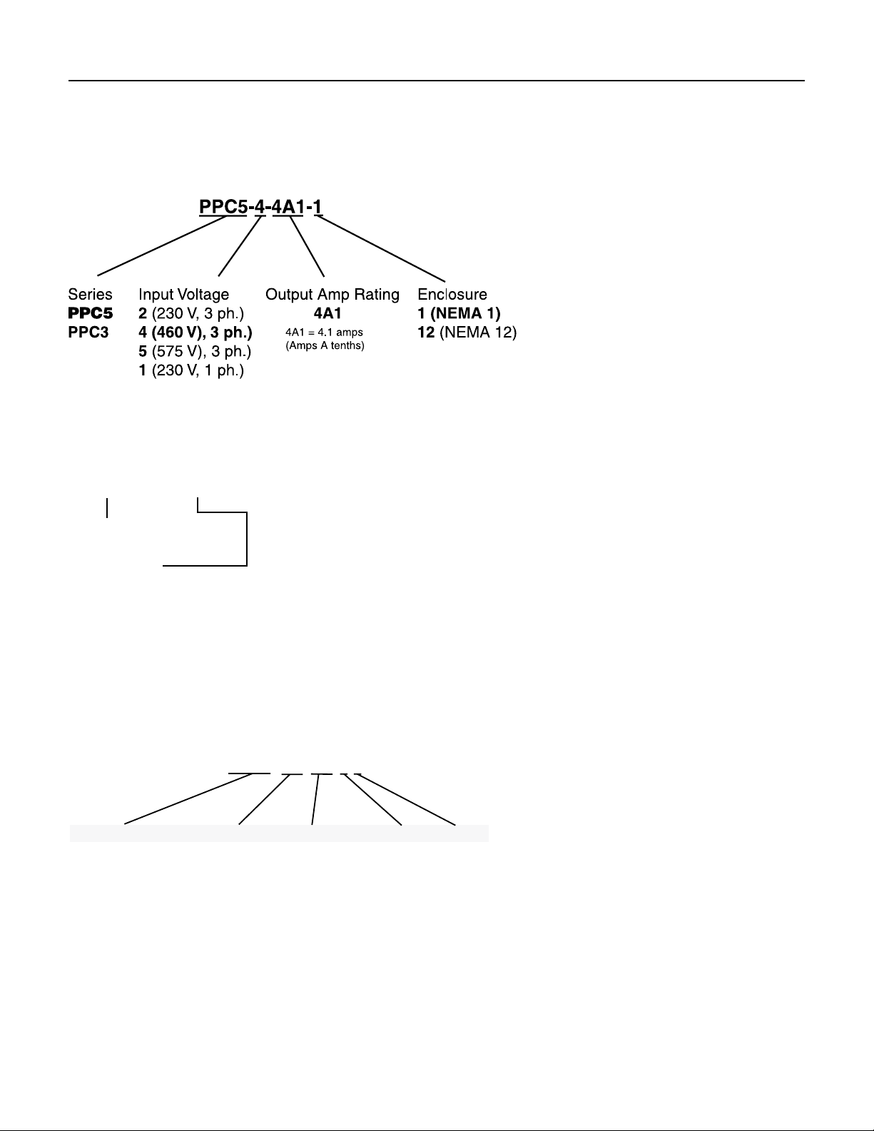
2.2 Drives
Variable / High Speed Drive Nomenclature
The chart below shows the naming for a PPC5, 460 volt,
4amp drive with a NEMA 1 enclosure.
Note that the output current (amps) of the control must
be greater than or equal to the maximum rated motor
current. Output of all drives is 3-phase power.
PID Variable Frequency Drive Nomenclature
Product Family
PID = Pentek IntelliDrive
HP Rating:
10 = up to 1 HP
20 = up to 2 HP
50 = up to 5 HP
2.3 Submersible Motor Controls
The chart below shows the naming for a Submersible
Motor control, Standard box, capacitor run, 5horsepower,
230 volt single phase drive.
ies
Style
)
CR (Cap Run)
IR (Induction Run)
CRP (Cap Run
with contactor)
HP x 10
05 (0.5 hp)
07 (.75 hp)
10 (1 hp)
15 (1.5 hp)
20 (2 hp)
30 (3 hp)
50 (5 hp)
Voltage
1 (115 v)
2 (230 v)
Phase
4

SECTION 3: Installation and Setup
3.1 General Installation Guidelines
• Inordertoavoidabrasiontothepowerandcontrol
cables, pad the top of the well casing (a rubber pad is
recommended) where the cable will pass over it; use
a cable reel for cable control.
• Theunitmustalwaysbeeasytorotateinthe
hoistinggear.
• Laypowerandcontrolcablesoutstraightonthe
ground (no loops) before installation. Guide cables
during lowering so that they are not stretched or
squeezed while pump is being installed. Make sure
that cable insulation is not nicked or damaged before
or during installation. Never use the electrical cables
to move the motor/pump.
• Thepumpandmotorareheavy.Makesurethatall
connections are secure and that the hoisting gear is
adequate to do the job before starting to lift pump.
Don’t stand under the unit. Don’t allow extra people
into the area while hoisting the unit.
• Ifmotororpump/motorunitareattachedtoa
supporting girder, do not remove girder until unit
isvertical.
• Installpumpatleast10’(3m)belowthelowestwater
level during pumping, but at least 6’ (2m) above the
bottom of the well.
• 6”motorscanbeoperatedinverticalorhorizontal
(when lead wire is at 12:00 position facing motor
flange) positions.
• 4”motorscanbeoperatedinverticalorhorizontal
positions. Note that the thrust bearing will have
shorter life in a non-vertical application. In such an
installation, keep frequency of starts to less than
10perday.
3.2 Proper Grounding
Hazardous voltage. Can shock, burn
or cause death. Installation or service to electrical
equipment should only be done by qualified electrician.
Control panels must be connected to supply ground
Proper grounding serves two main purposes:
1. It provides a path to ground in case of a ground-fault.
Otherwise the current would present a shock or
electrocution hazard.
2. It protects equipment from electrical surges.
Use wire the same size as, or larger than motor’s
current-carrying wires (consult Tables in the motor
section).
Installations must comply with the National Electric Code
as well as state and local codes.
All systems must have lightning (surge) protection with a
secure connection to ground.
An above ground lighting (surge) protection must be
grounded metal-to-metal and extend all the way to
the water bearing layer to be effective. Do not ground
the lightning (surge) protection to the supply ground
or to a ground rod as this will provide little or no surge
protection to the unit.
All motors are internally grounded and requires a 3 or
4-wire drop cable.
3.3 Corrosive Water and Ground
Some waters are corrosive, and can eventually corrode
the ground wire. If the installation uses a metal well
casing, any ground current will flow through it. In the
case of plastic piping and casing, the water column would
carry the current in a ground fault situation.
To prevent this, route the motor ground wire and the
motor power leads through a GFCI with a 10 mA set
point. In this way, the GFCI will trip when a ground fault
has occurred AND the motor ground wire is no longer
functional.
3.4 Check Valves
Check valve installation is necessary for proper pump
operation. The pump should have a check valve on its
discharge, or within 25 feet (7.62 m) of the pump. For very
deep wells, locate a check valve at least every 200 feet
(61m) vertical.
• Useonlyspringtypeorgravity-poppetcheck
valves. Swing type valves can cause water hammer
problems.
• Donotusedrain-backstylecheckvalves(drilled).
Check valves serve the following purposes:
• MaintainPressure:Withoutacheckvalve,thepump
has to start each cycle at zero head, and fill the drop
pipe. This creates upthrust in the motor, and would
eventually damage both the pump and motor.
• PreventWaterHammer:Iftwocheckvalvesareused,
and the lower one leaks, then a partial vacuum forms
in the pipe. When the pump next starts, the flow fills
the void area quickly, and creates a shock wave that
can break piping and damage the pump. If you get
water hammer on pump start, this may be the cause.
• PreventBack-Spin:Withoutafunctioningcheck
valve, upon shutoff, the water drains back through
the pump, and cause it to rotate backwards. This can
create excessive wear on the thrust bearing, and if the
pump restarts as water is flowing down the pipe, it
will put an excessive load on the system.
and Setup
Installation
5

SECTION 3: Installation and Setup
3.5 Start-Up
NOTICE: To avoid sand-locking pump, follow procedure
below when starting pump for the first time. NEVER start
a pump with discharge completely open unless you have
done this procedure first.
1. Connect a pipe elbow, a short length of pipe and a
gate valve to pump discharge at well head.
2. Make sure that controls will not be subjected to
extreme heat or excess moisture.
3. Make sure power is OFF. DO NOT START PUMP YET.
4. Set gate valve on discharge 1/3 open; start pump.
5 Keep gate valve at this setting while water pumps out
on ground. Let it run until water is clear of sand or
silt. (To check solids in water, fill a glass from pump
and let solids settle out).
6. When water is completely clear at 1/3 setting, open
gate valve to approximately two-thirds open and
repeatprocess.
7. When water is completely clear at 2/3 setting, open
gate valve completely and run pump until water is
completely clear.
8. Do not stop the pump until the water is clear.
Otherwise sand will accumulate in the pump stages
which may bind or freeze the pump.
9. Remove gate valve and make permanent installation.
NOTICE: The motor may draw higher than normal current
while the riser pipe is filling. After the riser pipe is full,
the amp draw should drop back to less than the allowed
current given on the motor nameplate.
When pump is in service, the amp draw must be
approximately equal to or lower than the service factor
amps given on the motor nameplate. If not, recheck
entire installation and electrical hook-up to find out why
amp draw is higher than normal.
Motor Torque
The motor exerts a strong torque force on the downpipe
and any other supporting structures when it starts. This
torque is usually in the direction that would unscrew
right-hand threads (the motor’s reaction movement is
clockwise as seen from above).
All pipe and pump joints must be tightened to safely
handle the starting torque. Tighten all threaded
joints to a minimum of 10 ft.-lb per horsepower.
i.e. 20 HP = 200ft.-lb; 50 HP = 500 ft.-lb.
Tack welding or strap welding may be required with
higher horsepower pumps.
6
SECTION 4: Electrical Power
Ser
4.1 Mixing Wire Size with Existing
Installation
Using two different cable sizes.
Sometimes conditions make it desirable to use more
than one size cable, such as replacing a pump in an
existinginstallation.
For example: Installing a pump with a 4”, 5 HP, 230
volt, single phase motor, with the motor setting at 370’
(112.8m) down the well and with 160’ (48.8m) of #8cable
buried between the service entrance and the wellhead.
160 Ft. AWG 8
370 Ft.
Pump
Controls
vice Entrance
(Main Fuse Box
From Meter)
5 HP (4.9 kw)
230V 1Ph Motor
Figure 4-1: Mixing Wire Sizes: Example
In order to avoid replacing the buried cable, the question
is: What size cable is required in the well? Calculate
asfollows:
1. According to Table 5-9, a total of 326’ (112.8m) of #8
cable is the maximum length cable to power a 5HP
motor. The percent of this total that has been used
by the 160’ (48.8m) of cable in the buried run is:
160’ / 326’ = .49 or 49%.
2. With 49% of the allowable cable already used, 51%
of the total length is left for use in the well. To avoid
running a cable that is too small (gauge) and lowering
the voltage to the motor, we have to find a cable size
large enough so that 370’ (112.8m) is less than 51%
of the total length allowed for that size.
3. 370 ÷ 51% = 726 feet.
4. From Table 5-9 we find that the total allowable length
for #4 cable is 809’ (246.6 m).
This is longer than needed. Therefore, #4 cable can
be used for the 370’ (112.8m) of cable in the well.
Any combination of sizes can be used, provided that
the total percentage of the length of the two sizes of
cable is not less than 100% of the allowed lengths.
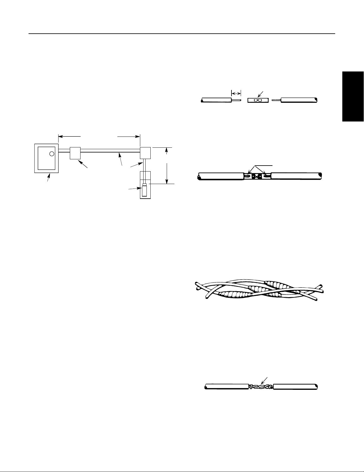
Cable
B. Cut off power supply wire ends. Match colors
and lengths of wires to colors and lengths of
motorleads.
C. Trim insulation back 1/2” (13mm) from supply
wire and motor lead ends (Figure 4-2).
1/2"
(12.7mm)
Butt Connector
Figure 4-2: Insert Wires
D. Insert motor lead ends and supply wire ends
into butt connectors. Match wire colors between
supply wires and motor leads.
E. Using crimping pliers, indent butt connector lugs
to attach wires (Figure 4-3).
Indent here
Figure 4-3: Indent Connectors
F. Cut Scotchfil
™
electrical insulation putty into
3 equal parts and form tightly around butt
connectors. Be sure Scotchfil overlaps insulated
part of wire.
G. Using #33 Scotch® tape, wrap each joint tightly;
cover wire for about 1-1/2” (38mm) on each side
of joint. Make four passes with the tape. When
finished you should have four layers of tape tightly
wrapped around the wire. Press edges of tape
firmly down against the wire (Figure 4-4).
Completed splice
Figure 4-4: Wrap Splices
NOTICE: Since tightly wound tape is the only means
of keeping water out of splice, efficiency of splice will
depend on care used in wrapping tape.
NOTICE: For wire sizes larger than No. 8 (7mm2), use
soldered joint rather than Scotchfil putty, Figure 4-5.
Alternate method
twist and solder
Electrical Power
4.2 Wire Splicing
Splice wire to motor leads. Use only copper wire for
connections to pump motor and control box.
1. Taped splice (for larger wire sizes)
A. Stagger lead and wire length so that 2nd lead is
2” (50mm) longer than 1st lead and 3rd lead is
2”(50mm) longer than second.
Figure 4-5: Twist Wires
Scotchfil™ is a trademark of 3M Company.
Scotch is a registered trademark of 3M Company.
7
SECTION 4: Electrical Power
2. Heat shrink splice (For wire sizes #14, 12 and 10 AWG
2
(2, 3 and 5mm
):
A. Remove 3/8” (9.5mm) insulation from ends of
motor leads and power supply wires.
B. Put plastic heat shrink tubing over motor leads
between power supply and motor.
C. Match wire colors and lengths between power
supply and motor.
D. Insert supply wire and lead ends into butt
connector and crimp. Match wire colors
between power supply and motor. Pull leads to
checkconnections.
E. Center tubing over butt connector and apply heat
evenly with a torch (match or lighter will not
supply enough heat, Figure 4-6).
Connector
Heat shrink tubing
Figure 4-6: Heat-Shrink Tubing Applied
NOTICE: Keep torch moving. Too much concentrated heat
may damage tubing.
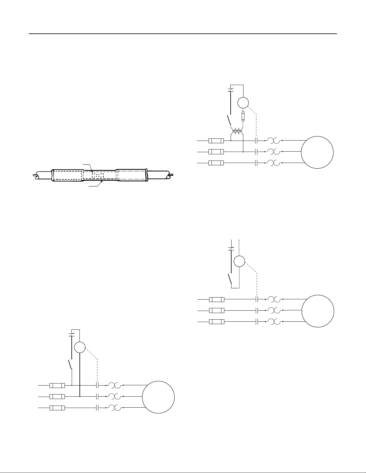
Low Voltage Control
This starter arrangement uses a transformer to allow
the coil to be energized by a lower voltage. Note that the
secondary circuit must be fused, and the coil sized for the
secondary voltage.
Overload
Control
Coil
Control
Device
Thermal
Overload
L1
L2
Heaters
3-Phase
Motor
L3
Figure 4-8: Low Voltage Control
Separate Voltage Control
This arrangement uses power from a separate source to
energize the coil.
4.3 3-Phase Starters
Starters are used to start the motor by engaging contacts
that will energize each line simultaneously. The contacts
are closed when the coil is energized.
Figures 4-7 through 4-9 show three types of starters used
on the motors. The control device in the secondary circuit
is typically a pressure switch. Other control could be
provided by level control, timers or manual switches.
Line Voltage Control
This commonly-used control has a coil energized by line
voltage. The coil voltage matches the line voltage.
Overload
Control
Coil
Control
Device
Thermal
Overload
L1
L2
L3
Heaters
3-Phase
Motor
Separate
Voltage
Overload
Control
Coil
Control
Device
Thermal
Overload
L1
L2
L3
Heaters
Figure 4-9: Separate Voltage Control
3-Phase
Motor
Figure 4-7: Line Voltage Control
8
SECTION 4: Electrical Power
Starter
L1
L2
L3
T1
T2
T3
Arrangement 1
Starter
L1
L2
L3
T1
T2
T3
Arrangement 2 Arrangement 3
Starter
L1
L2
L3
T1
T2
T3
Arrangement 3
4.4 Checking Motor Rotation
To check rotation before the pump is installed, follow
thesesteps:
During testing or checking rotation (such as “bumping”
or “inching”) the number of “starts” should be limited to
3and total run time of less than 15 seconds.
Bumping must be done while motor is in horizontal
position and followed by a full 15 minute cooling-off
period before any additional “starts” are attempted.
Energize the motor
briefly, and observe the
direction of rotation.
It should be counterclockwise when viewed
from the pump (shaft)
end.
To check rotation after
the pump is installed:
NOTICE: NEVER
continuously operate a
pump with the discharge
valve completely closed
(dead head). This can overload the motor due to lack of
cooling, or destroy the pump and will void the warranty.
After energizing the motor, check the flow and pressure
of the pump to make sure that the motor is rotating in the
correct direction. To correct a wrong rotation, switch any
two of the three cable connections (three-phase motor
only). The setting that gives the most flow and pressure is
correct.
A cooling-off period of 15 minutes is required
betweenstarts.
Hazardous voltage. Disconnect power
before working on wiring.
Input voltage, current and insulation resistance values
should be recorded throughout the installation and
should be used for preventive maintenance.
Figure 4-10: Motor Rotation
Here is an example of current readings at maximum
pump loads on each leg of a three wire hookup. Make
calculations for all three possible hookups.
A. For each hookup, add the readings for the three legs.
B. Divide each total by three to get average amps.
C. For each hookup, find current value farthest from
average (Calculate the greatest current difference
from the average).
D. Divide this difference by the average and multiply by
100 to obtain the percentage of unbalance.
Use smallest percentage unbalance, in this case
Arrangement 2 (Table 4.1).
Us e the Current-Balance worksheet
located in the Installation Record
After trying all three lead hookups, if the reading furthest
from average continues to show on the same power lead,
most of the unbalance is coming from the power source.
Call the power company.
If the reading furthest from average changes leads as the
hookup changes (that is, stays with a particular motor
lead), most of the unbalance is on the motor side of the
starter. This could be caused by a damaged cable, leaking
splice, poor connection, or faulty motor winding.
Starter
L3
T3
Electrical
Power
Supply
L2
L1
Arrangement 2
Starter
L3
T2
T1
L2
To Motor
T2
T1
Electrical Power
4.5 3-Phase Current Balancing
Current Unbalance Test
Before checking for current unbalance, the pump must
be started, and rotation direction determined.
Determine current unbalance by measuring current in
each power lead. Measure current for all three possible
hookups (Figure 4-11). Use example and worksheet on
the Installation Checklist and Record in Section 12 to
calculate current unbalance on a three phase supply
system and retain for future reference.
NOTICE: Current unbalance between leads should not
exceed 5%. If unbalance cannot be corrected by rolling
the leads, locate the source of the unbalance.
L1
T3
Arrangement 3
Starter
L3
T1
L2
T3
L1
T2
Figure 4-11: 3-Phase Current Unbalance: Example
9
SECTION 4: Electrical Power
Use this worksheet to calculate current unbalance for our
installation.
Table 4-1: Electrical Current Unbalance Example
Arrangement 1
Amps
EXAMPLE
Total Amps 50 50 50
Average Amps 50 ÷ 3 = 16.7 50 ÷ 3 = 16.7 50 ÷ 3 =16.7
From Average Amps
Deviation L1
Deviation L2
Deviation L3
% Current Unbalance
Largest Deviation
% Unbalance + 8.4% 2.4% 4.2%
L1–T1=17
L2–T2=15.3
L3–T3=17.7
0.3
1.4
1.0
1.4 ÷ 16.7 0.4 ÷ 16.7 0.7 ÷ 16.7
Arrangement 2
Amps
L1–T3=16.7
L2–T1=16.3
L3–T2=17
0.0
0.4
0.3
Arrangement 3
Amps
L1–T2=16.7
L2–T3=16
L3–T1=17.3
0.0
0.7
0.6
4.6 Transformer Sizing
A full three-phase power supply is recommended
for all three-phase motors and may consist of three
individual transformers or one three-phase transformer.
“Open” delta or wye connections which use only two
transformers can be used, but are more likely to cause
unbalanced current problems. Transformer ratings
should be no smaller than listed in Table 4-2 for supply
power to the motor alone.
T1
T2
Full 3-Phase (Delta)
T3
Figure 4-12: Three Phase Power
Transformers are rated by KVA capacity. This must be
high enough capacity for the motor being installed. If the
transformer capacity is too small, the motor will receive
reduced voltage and may be damaged.
Any other loads in the system would be in addition to the
motor alone.
Refer to Table 4-2. Note that the open delta configuration
can only use 87% of the rated power of the two
transformers.
T1 T2 T3
Wye or Open Delta 3-Phase
Table 4-2: Transformer Capacity
KVA Rating (smallest) For Each Transformer
HP kW
1/2 0.37 1.5 1.0 0.5
3/4 0.55 1.5 1.0 0.5
1 0.75 2.0 1.5 0.75
1-1/2 1.1 3.0 2.0 1.0
2 1.5 4.0 2.0 1.5
3 2.2 5.0 3.0 2.0
5 3.7 7.5 5.0 3.0
7.5 5.5 10.0 7.5 5.0
10 7.5 15.0 10.0 5.0
15 11.0 20.0 15.0 7.5
20 15.0 25.0 15.0 10.0
25 18.5 30.0 20.0 10.0
30 22.0 40.0 25.0 15.0
40 30.0 50.0 30.0 20.0
50 37.0 60.0 35.0 20.0
60 45.0 75.0 40.0 25.0
Required KVA
Open WYE or D
2Transformers
3Transformers
WYE or D
10

SECTION 4: Electrical Power
4.7 Using a Generator
Selecting a generator
Select a generator that can supply at least 65% of rated
voltage upon start-up of the motor.
The chart shows ratings of generators, both externally
and internally regulated. This chart is somewhat
conservative. Consult the generator manufacturer if you
are uncertain.
Table 4-3: Ratings of Generators
Motor Externally Regulated Internally Regulated
HP kW KVA kW KVA
1/2 2.0 2.5 1.5 1.9
3/4 3.0 3.8 2.0 2.5
1 4.0 5.0 2.5 3.1
1-1/2 5.0 6.3 3.0 3.8
2 7.5 9.4 4.0 5.0
3 10.0 12.5 5.0 6.25
5 15.0 18.8 7.5 9.4
7-1/2 20.0 25.0 10.0 12.5
10 30.0 37.5 15.0 18.8
15 40.0 50.0 20.0 25.0
20 60.0 75.0 25.0 31.0
25 75.0 94.0 30.0 37.5
30 100.0 125.0 40.0 50.0
40 100.0 125.0 50.0 62.5
50 150.0 188.0 60.0 75.0
60 175.0 220.0 75.0 94.0
Frequency
It is highly important that the generator maintain
constant frequency (Hz), since the motor’s speed depends
uponfrequency.
A drop of just 1 to 2 Hz can noticeably lower pump
performance. An increase of 1 to 2 Hz can cause
overloadconditions.
Generator Operation
Start the generator before starting the pump motor.
The pump motor must be stopped before turning off
thegenerator.
If the generator runs out of fuel, and the pump is still
connected, it will put excess strain on the thrust bearings
as the generator slows.
Risk of electrocution. Use transfer
switches when the generator is used as a backup to the
power grid. Contact your power company or generator
manufacturer for proper use of standby or backup
generators.
4.8 Special Applications
Using Phase Converters
Phase converters allow three-phase motors to operate
from one-phase supply. Various styles of phase
converters are available. Many converters do not supply
a properly balanced voltage, and using these will void the
motor’s warranty unless approval is obtained first.
Guidelines For Phase Converters:
• Currentunbalancemustbelessthan5%.
• Convertertobesizedtoservicefactorcapacity
• Maintainmotorcoolingwithacoolingflowofatleast
3’ per second.
• Fusesandcircuitbreakersmustbetime-delaytype.
Motor Starting with Reduced Voltage
Starting a motor with full voltage will bring it to full speed
in less than 1/2 second. This can:
• Spiketheloadcurrent,causingbriefvoltagedipsin
other equipment.
• Over-stresspumpandpipingcomponentsbecauseof
high torque.
• Causewaterhammer.
Electrical Power
Voltage Regulation
There is a significant difference in the performance of
internally and externally regulated generators.
An external regulator senses output voltage dips
and triggers an increase in the voltage output of the
generator.
An internal regulator, senses current and responds to
increased current by supplying more voltage.
Motor Starters (3-Phase Only)
Various types of motor starters are available.
Autotransformers are recommended because of reduced
current draw.
When motor starters are used, they should supply
a minimum of 55% of rated voltage for adequate
startingtorque.
11

SECTION 5: XE Series 4” Submersible Motors
5.1 Motor Inspection
Check the motor for damage in shipping.
Before installation, check the following.
• Checkoveralltools,especiallythehoistinggear,for
wear or damage before hoisting unit.
• Inspectthemotorcableforanynicksorcuts.
• Verifythatmotornameplatedatamatches
registration card information exactly.
• Verifythatmotornameplatevoltageiscorrectfor
available power supply voltage. Voltage must not vary
more than +/-10% from nameplate rated voltage.
• Verifythatthewelldiameterislargeenoughto
accommodate the motor/pump unit all the way to the
pump setting depth.
• Forinstallationswithtightwellcasings,makesure
that riser pipe flanges are recessed to protect
the power and control cables from abrasion and
squeezing during installation.
Heavy object. Lifting equipment must be
capable of lifting motor and attached equipment.
• Ifthetotallengthofthepumpmotorunit(without
any riser pipe) exceeds 10’ (3m), the unit must be
supported with a girder while hoisting. Do not remove
supporting girder until unit is standing vertically in the
hoist. Check for damage.
5.2 Testing
Insulation Resistance
To check for insulation resistance:
1. Disconnect power to the motor for this test.
2. Connect an Ohm meter (resistance in Ω) between the
power leads and the motor ground or well casing.
20KΩ Damaged motor, possible result of
lightning strike.
500KΩ Typical of older installed motor in well.
2 MΩ Newly installed motor
10 MΩ Used motor, measured outside of well
20 MΩ New motor without cable
5.3 Storage and Transportation
The motors are filled with a non-toxic, Propylene Glycol
and water solution to prevent damage from freezing
temperatures. The solution will prevent damage from
freezing temperatures to -40˚F (-40˚ C). Motors should
be stored in areas that do not go below this temperature.
The solution will become slushy between 0˚F (-17˚C) and
-40˚F (-40˚C) but no damage occurs. If this occurs, allow
the motor to sit in the well for several minutes before
operating.
Storage site should be clean, well vented, and cool.
Keep humidity at the storage site as low as possible.
Protect motor and cables from direct sunlight.
Protect power supply cables and control cables from
moisture by taping the cable ends with electrician’s tape.
Do not kink power supply or control cables.
Take care when moving unit (packed or unpacked) with
crane or hoisting gear not to knock it against walls, steel
structure, floors, etc. Do not drop motor.
Do not lift motor or motor/pump unit by power supply or
control cables.
12

SECTION 5: XE Series 4” Submersible Motors
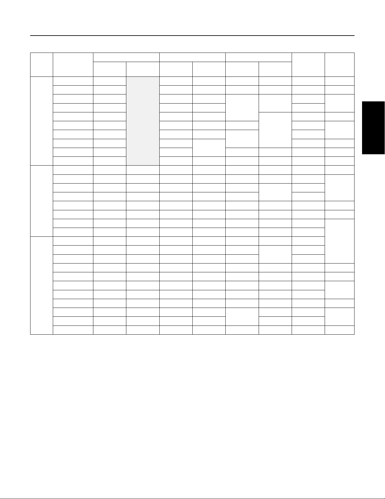
5.4 4” Motor Specifications
Table 5-1: Single Phase Motor Specifications (115 and 230 Volt, 60 Hz, 3450 RPM)
Motor Type
PSC
2-Wire
CSIR
3-Wire
CSCR
3-Wire
Pentek® Part
Number
P42B0010A2-01 7.9 1679 9.1 1990
P42B0015A2-01 9.2 2108 11.0 2520
P42B0005A1-01 7.9 910 9.8 1120
P42B0005A2-01 4.0 845 4.7 1050
P42B0007A2-01 5.0 1130 6.2 1400
P42B0010A2-01 6.7 1500 8.1 1800
P42B0015A2-01 9.0 2000 10.4 2350
P42B0005A1 7.4 845 9.5 1088
P42B0005A2 3.7 834 4.7 1073
P42B0007A2 5.0 1130 6.4 1459
P43B0005A1-01 8.8/8.8/0 8.8 675 10.9/10.9/0 10.9 980
P43B0005A2-01 5.3/5.3/0 5.3 740 6.1/6.1/0 6.1 1050
P43B0007A2-01 6.6/6.6/0 6.6 970 7.8/7.8/0 7.8 1350
P43B0010A2-01 8.1/8.1/0 8.1 1215 9.4/9.4/0 9.4 1620
P43B0005A1 11.0/11.0/0 11.0 733 12.6/12.6/0 12.6 1021
P43B0005A2 5.5/5.5/0 5.5 745 6.3/6.3/0 6.3 1033
P43B0007A2 7.2/7.2/0 7.2 1014 8.3/8.3/0 8.3 1381
P43B0010A2 8.4/8.4/0 8.4 1267 9.7/9.7/0 9.7 1672
P43B0005A2-01 4.2/4.1/1.8 4.2 7.15 4.8/4.3/1.8 4.8 960
P43B0007A2-01 4.8/4.4/2.5 4.8 940 6.0/4.9/2.3 6.0 1270
P43B0010A2-01 6.1/5.2/2.7 6.1 1165 7.3/5.8/2.6 7.3 1540
P43B0015A2-01 9.1/8.2/1.2 9.1 1660 10.9/9.4/1.1 10.9 2130
P43B0005A2 4.1/4.1/2.2 4.1 720 4.9/4.4/2.1 4.9 955
P43B0007A2 5.1/5.0/3.2 5.1 1000 6.3/5.6/3.1 6.3 1300
P43B0010A2 6.1/5.7/3.3 6.1 1205 7.2/6.3/3.3 7.2 1530
P43B0015A2 9.7/9.5/1.4 9.7 1693 11.1/11.0/1.3 11.1 2187
P43B0020A2 9.9/9.1/2.6 9.9 2170 12.2/11.7/2.6 12.2 2660
P43B0030A2 14.3/12.0/5.7 14.3 3170 16.5/13.9/5.6 16.5 3620
P43B0050A2 24/19.1/10.2 24.0 5300 27.0/22.0/10.0 27 6030
Amps (Y/B/R) Y Only Watts Amps (Y/B/R) Y Only Watts
Full Load Service Factor
XE Series Motors
13

SECTION 5: XE Series 4” Submersible Motors
Table 5-2: Three Phase Motor Specifications (230, 460, 200 and 575 Volt, 60 Hz, 3450 RPM)
Pentek® Part
Number
P43B0005A8
P43B0005A3 230 2.4 610 2.9 880
P43B0005A4 460 1.3 610 1.5 875
P43B0007A8
P43B0007A3 230 3.3 850 3.9 1185
P43B0007A4 460 1.7 820 2.0 1140
P43B0010A8
P43B0010A3 230 4.0 1090 4.7 1450
P43B0010A4 460 2.2 1145 2.5 1505
P43B0015A8
P43B0015A3 230 5.2 1490 6.1 1930
P43B0015A4 460 2.8 1560 3.2 1980
P43B0015A5 575 2 1520 2.4 1950
P43B0020A8
P43B0020A3 230 6.5 1990 7.6 2450
P43B0020A4 460 3.3 2018 3.8 2470
P43B0020A5 575 2.7 1610 3.3 2400
P43B0030A8
P43B0030A3 230 9.2 2880 10.1 3280
P43B0030A4 460 4.8 2920 5.3 3320
P43B0030A5 575 3.7 2850 4.1 3240
P43B0050A8
P43B0050A3 230 15.7 4925 17.5 5650
P43B0050A4 460 7.6 4810 8.5 5530
P43B0050A5 575 7.0 5080 7.6 5750
P43B0075A8
P43B0075A3 230 24.0 7480 26.4 8570
P43B0075A4 460 12.2 7400 13.5 8560
P43B0075A5 575 9.1 7260 10.0 8310
P43B0100A4 10 7.5 460 15.6 9600 17.2 11000
HP kW Volts Hz
1/2 0.37
3/4 0.55
1 0.75
1-1/2 1.1
2 1.5
3 2.2
5 3.7
7-1/2 5.6
Rating Full Load Maximum Load (SF Load)
Service
Factor
200
1.6
200
1.5
200
1.4
200
1.3
200
60
200
200 18.3 4850 20.2 5515
200 27.0 7600 30.0 8800
1.25
1.15
Amps Watts Amps Watts
2.9 600 3.4 870
3.8 812 4.5 1140
4.6 1150 5.5 1500
6.3 1560 7.2 1950
7.5 2015 8.8 2490
10.9 2890 12.0 3290
14
SECTION 5: XE Series 4” Submersible Motors
Table 5-3: Single Phase 4” Motor Electrical Parameters (115 and 230 Volt, 60 Hz, 3450 RPM, 2 and 3 wire)
Motor
Type
PSC
2-Wire
CSIR
3-Wire
CSCR
3-Wire
Pentek® Part
Number
P42B0005A1-01 1.4-2.0 42.1 54 99.6 99.9 28 H
P42B0005A2-01 6.1-7.2 45 58.5 92 97 16 J
P42B0007A2-01 5.9-6.9 50.5 61
P42B0010A2-01 4.2-5.2 50 59 24
P42B0015A2-01 1.8-2.4 56.5 62.5
P42B0005A1 1.3-1.8 49 61 99 36.4
P42B0005A2 4.5-5.2 50 62
P42B0007A2 3.0-4.8 55
P42B0010A2 4.2-5.2 58 94 96 21.7 F
P42B0015A2 1.9-2.3 59 64 99 99 42 H
P43B0005A1-01 1.0-1.4 2.5-3.1 57 62 65 78 44 M
P43B0005A2-01 5.1-6.1 12.4-13.7 52 58.5 61 75 21
P43B0010A2-01 2.0-2.6 9.3-10.4 63 66 66 41
P43B0005A1 0.9-1.6 5.7-7.0 51 59 54 69 49.6 N
P43B0005A2 4.2-4.9 17.4-18.7 50 58 58 71 22.3 M
P43B0007A2 2.6-3.6 11.8-13.0 55 61 61 72 32
P43B0010A2 2.2-3.2 11.3-12.3 59 62 66 75 41.2
P43B0005A2-01 5.1-6.1 12.4-13.7 54.5 61.5 77 87 21
P43B0007A2-01 2.6-3.3 10.4-11.7 62 69 86
P43B0010A2-01 2.0-2.6 9.3-10.4 66 71 86 41
P43B0015A2-01 2.1-2.5 10.0-10.8 68 69 81 87 49 J
P43B0005A2 4.2-4.9 17.4-18.7 52 62 76 85 22.3 M
P43B0007A2 2.6-3.6 11.8-13.0 56 65 85 90 32
P43B0010A2 2.2-3.2 11.3-12.3 62 68 86 92 41.2
P43B0015A2 1.6-2.3 7.9-8.7 66 67 80 85 47.8 J
P43B0020A2 1.6-2.2 10.8-12.0 68 69
P43B0030A2 1.1-1.4 2.0-2.5 72 72 97 76.4
P43B0050A2 0.62-0.76 1.36-1.66 71 71 97 98 101 E
Resistance *
Winding Efficiency % Power Factor %
Main
Start
Resistance
FL SF FL SF
98
97
65
96
Locked Rotor
Amps
98
99
76
91
95 49.4
18
44 H
19.5
24.8 J
32
32
KVA Code
F
K
XE Series Motors
LP43B0007A2-01 2.6-3.3 10.4-11.7 60 64.5 64
L
L
G
* Main winding is between the yellow and black leads. Start winding is between the yellow and red leads.
15

SECTION 5: XE Series 4” Submersible Motors
Table 5-4: T
Pentek® Part
P43B0005A8 4.1-5.2 62 68.5 22
P43B0005A3 5.72-7.2
P43B0005A4 23.6-26.1 9
P43B0007A8 2.6-3.0 69 74 32
P43B0007A3 3.3-4.3 66 71 27
P43B0007A4 14.4-16.2 69 73.5 14
P43B0010A8 3.4-3.9 66 70 29
P43B0010A4 17.8-18.8 65 69 13
P43B0015A8 1.9-2.5 72 74 40
P43B0015A4 12.3-13.1 72 73 16.3
P43B0015A5 19.8-20.6 73 74 11.5 J
P43B0020A8 1.4-2.0 74
P43B0020A4 8.00-8.67 74 23
P43B0020A5 9.4-9.7 78 78 21.4 M
P43B0030A8 0.9-1.3
P43B0030A3 1.3-1.7 58.9
P43B0030A4 5.9-6.5 76 30
P43B0030A5 9.4-9.7 78 78 21.4
P43B0050A8 0.4-0.8
P43B0050A3 .85-1.25 93
P43B0050A4 3.58-4.00 77 77 48
P43B0050A5 3.6-4.2 75 75 55 M
P43B0075A8 0.5-0.6 74 74 165
P43B0075A3 0.55-0.85 75 75 140
P43B0075A4 1.9-2.3 76 76 87 L
P43B0075A5 3.6-4.2 77 77 55 J
P43B0100A4 1.8-2.2 79 80 110 K
Number
hree Phase
Motor Electrical Parameters (230, 460, 200 and 575 Volt, 60 Hz, 3450 RPM)
Line to Line Resistance Ohms
% Efficiency
FL SF
61 68
75
77
76 76
77
Locked Rotor Amps KVA Code
17.3
51
71 K
113
R
MP43B0010A3 4.1-5.1 69 72 26.1
LP43B0015A3 2.8-3-4 75 76 32.4
KP43B0020A3 1.8-2.4 75 44
J
J
16

SECTION 5: XE Series 4” Submersible Motors
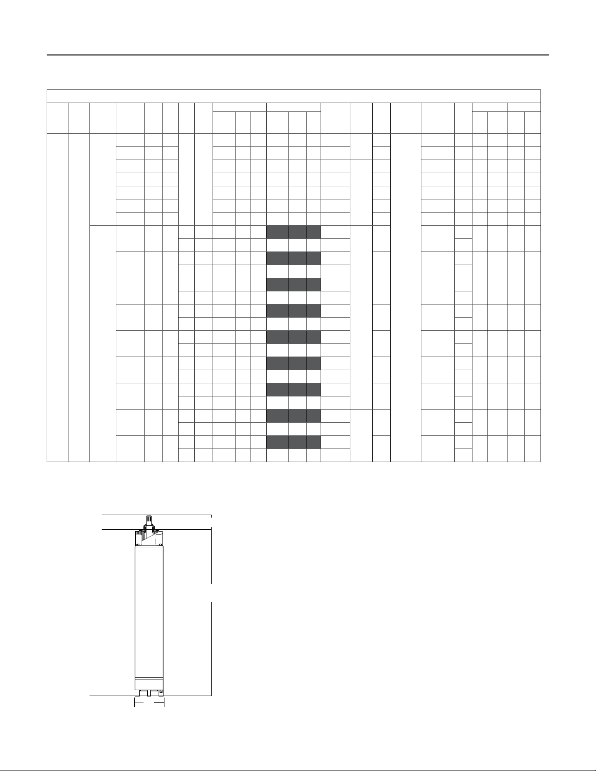
5.5 4” Motor Dimensions
Table 5-5: Single Phase Motor Dimensions (115 and 230 Volt, 60 Hz, 3450 RPM)
Motor Type
4-Inch
2-Wire
4-inch
3-Wire
Pentek® Part
Number
P42B0005A1-01
P42B0005A2-01
P42B0007A2-01 3/4 0.55 11.9 302 21.4 9.7
P42B0010A2-01 1 0.75 12.5 318 23.2 10.5
P42B0015A2-01 1-1/2 1.1 14.2 361 27.3 12.4
P42B0005A1
P42B0005A2
P42B0007A2 3/4 0.55 12.4 314 22.7 10.3
P42B0010A2 1 0.75 13.3 337 24.5 11.1
P42B0015A2 1-1/2 1.1 14.9 378 28.9 13.1
P43B0005A1-01
P43B0005A2-01 9.2 234 16.7 7.6
P43B0007A2-01 3/4 0.55 10.3 262 19.8 9.0
P43B0010A2-01 1 0.75 11.2 284 22.0 10.0
P43B0005A1
P43B0005A2 9.7 246 18.1 8.2
P43B0007A2 3/4 0.55 10.8 275 21.4 9.7
P43B0010A2 1 0.75 11.7 297 23.1 10.5
P43B0005A2-01 1/2 0.37 9.2 234 16.7 7.6
P43B0007A2-01 3/4 0.55 10.3 262 19.8 9.0
P43B0010A2-01 1 0.75 11.2 284 22.0 10.0
P43B0015A2-01 1-1/2 1.1 12.8 325 26.0 11.8
P43B0005A2 1/2 0.37 9.7 246 18.1 8.2
P43B0007A2 3/4 0.55 10.8 275 21.4 9.7
P43B0010A2 1 0.75 11.7 297 23.1 10.5
P43B0015A2 1-1/2 1.1 13.6 345 27.4 12.4
P43B0020A2 2 1.5 15.1 383 31.0 14.1
P43B0030A2 3 2.2 18.3 466 40.0 18.1
P43B0050A2 5 3.7 27.7 703 70.0 31.8
HP kW
1/2 0.37 10.5 267 18.1 8.2
1/2 0.37 11.0 279 19.2 8.7
1/2 0.37
1/2 0.37
Inches mm Lb Kg
Length Weight
9.6 244 17.9 8.1
10.0 253 18.9 8.6
XE Series Motors
17

SECTION 5: XE Series 4” Submersible Motors
Table 5-6: Three Phase Motor Dimensions (230, 460, 200 and 575 Volt, 60 Hz, 3450 RPM)
Pentek® Part Number HP kW
P43B0005A8
1/2 0.37 10 254 18.9 8.6P43B0005A3
P43B0005A4
P43B0007A8
3/4 0.55 10.8 275 21.4 9.7P43B0007A3
P43B0007A4
P43B0010A8
P43B0010A3
P43B0010A4
P43B0015A8
P43B0015A3
P43B0015A4
P43B0015A5
P43B0020A8
P43B0020A4
P43B0020A5
P43B0030A8
P43B0030A3
P43B0030A4
P43B0030A5
P43B0050A8
P43B0050A4
P43B0050A5
P43B0075A8
P43B0075A3
P43B0075A4
P43B0075A5
P43B0100A4 10 7.5 30.7 780 78 35.4
1 0.75
1-1/2 1.1
2 1.5
3 2.2
5 3.7
7-1/2 5.6
Inches mm Lb Kg
11.7 297 23.1 10.5
13.8 351 27.4 12.4P43B0020A3
15.3 389 32 14.5
21.7 550 55 24.9P43B0050A3
27.7 703 70 31.8
Length Weight
18
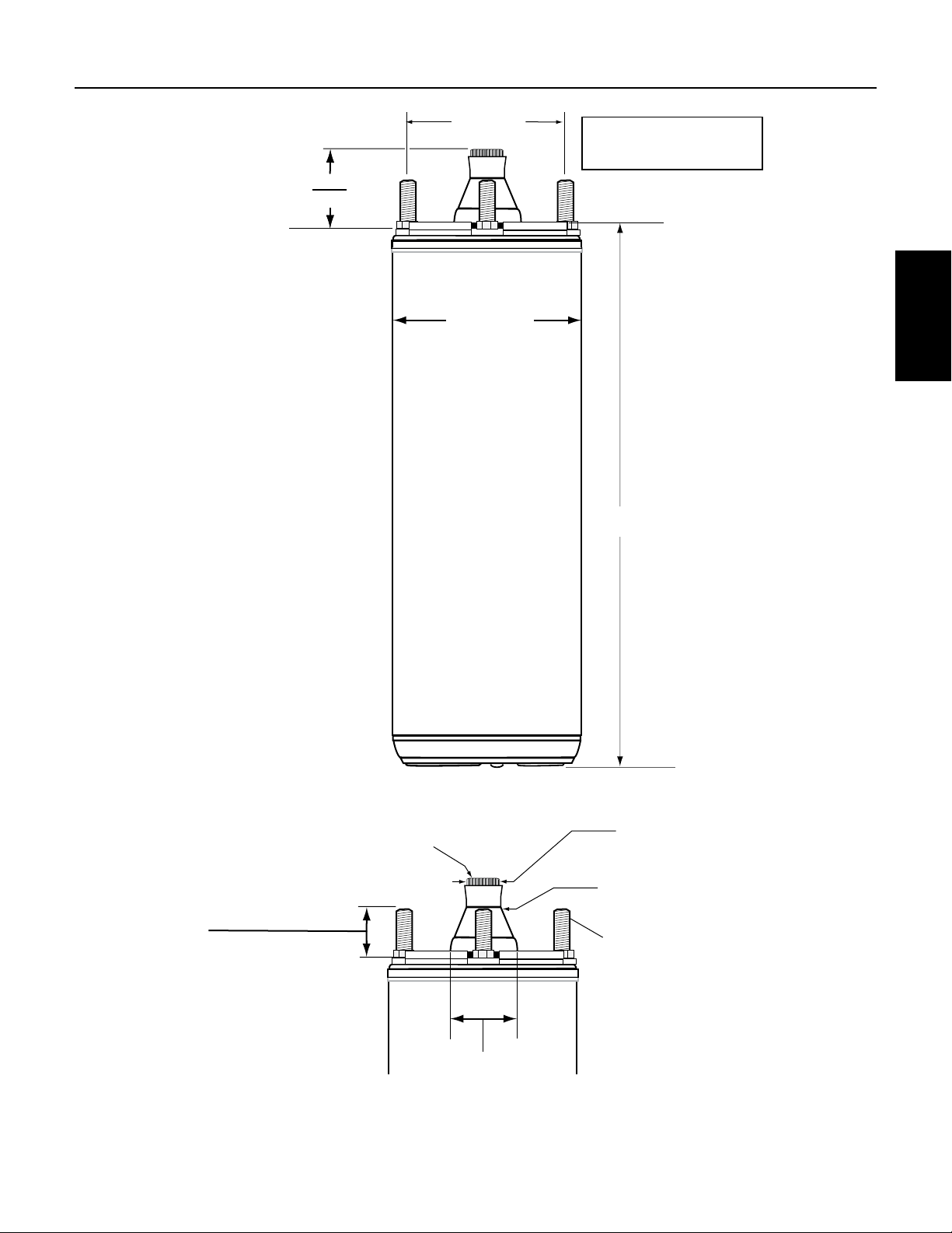
SECTION 5: XE Series 4” Submersible Motors
3.00 (7.62)
Shaft free end-play
.005 -.040 (.127 - 1.02)
1.508 (38.30)
1.498 (38.05)
All dimensions
in inches (mm)
3.750 (95.2)
XE Series Motors
4” Motor
Length
14 Teeth 24/48 Pitch
30 Degee Pressure Angle
Min 0.50 (23.1) Full Spline
ANSI B92.1 Compliant
0.97 (24.6) max
0.79 (20.1) min
1.5 (38.1)max.
Figure 5-1: XE Series 4” Motor Dimensions – Single and Three Phase
0.6255 (15.89)
0.6245 (15.86)
Sand Boot
(4) 5/16 - 24
UNF-2A Threaded
Studs on 3” (76.2)
Dia. Circle
19

SECTION 5: XE Series 4” Submersible Motors
5.6 4” Motor Fuse Sizing
Table 5-7: SINGLE PHASE Motor Fuse Sizing (115 and 230 Volt, 60 Hz, 3450 RPM)
Fuse Sizing Based on NEC
Motor Type Pentek® Part Number HP kW Volts
4-Inch
PSC
2-Wire
4-Inch
CSIR
3-Wire
4-Inch
CSCR
3-Wire
P42B0005A1-01
P42B0005A2-01
P42B0007A2-01 3/4 0.55 20
P42B0010A2-01 1 0.75 25
P42B0015A2-01 1-1/2 1.1 35 20 30
P42B0005A1
P42B0005A2
P42B0007A2 3/4 0.55 20 15
P42B0010A2 1 0.75 25
P42B0015A2 1-1/2 1.1 30 25
P43B0005A1-01
P43B0005A2-01
P43B0007A2-01 3/4 0.55 20 20
P43B0010A2-01 1 0.75 25 15 25
P43B0005A1
P43B0005A2
P43B0007A2 3/4 0.55 20 20
P43B0010A2 1 0.75 25 15 25
P43B0005A2-01 1/2 0.37 15
P43B0007A2-01 3/4 0.55
P43B0010A2-01 1 0.75
P43B0015A2-01 1-1/2 1.1 30 15 25
P43B0005A2 1/2 0.37 15
P43B0007A2 3/4 0.55
P43B0010A2 1 0.75
P43B0015A2 1-1/2 1.1 30 15 25
P43B0020A2 2 1.5 30 20 25
P43B0030A2 3 2.2 45 25 40
P43B0050A2 5 3.7 70 40 60
1/2 0.37
1/2 0.37
1/2 0.37
1/2 0.37
115 30 20 25
230
115 25 15 20
230
115 30 20 30
230
115 30 20 30
230
Standard Fuse Dual Element Time Delay Fuse
15 10 15
15
15
15
20 15
20 15
Circuit
Breaker
15 20
10
15
10
10
10
10
10
20
15
15
10
10
20

SECTION 5: XE Series 4” Submersible Motors
Table 5-8: THREE PHASE Motor Fuse Sizing (230, 460, 200 and 575 Volt, 60 Hz, 3450 RPM)
Pentek®
Part Number
P43B0005A8
P43B0005A3 230 6 6 6
P43B0005A4 460 3 3 3
P43B0007A8
P43B0007A3 230 6 6 6
P43B0007A4 460 3 6 3
P43B0010A8
P43B0010A3 230 10 6 10
P43B0010A4 460 6 3 6
P43B0015A8
P43B0015A3 230 15 10 15
P43B0015A4 460 10 6 6
P43B0015A5 575 6 3 6
P43B0020A8
P43B0020A3 230 15 15 20
P43B0020A4 460 15 6 10
P43B0020A5 575 10 6 10
P43B0030A8
P43B0030A3 230 25 15 25
P43B0030A4 460 15 10 15
P43B0030A5 575 10 10 10
P43B0050A8
P43B0050A3 230 45 30 40
P43B0050A4 460 25 15 20
P43B0050A5 575 20 15 20
P43B0075A8
P43B0075A3 230 70 45 60
P43B0075A4 460 40 25 35
P43B0075A5 575 25 20 25
P43B0100A4 10 7.5 460 45 25 35
HP kW Volts
200 10 6 10
1/2 0.37
200 15 10 10
3/4 0.55
200 15 10 10
1 0.75
200 20 10 15
1-1/2 1.1
200 25 15 20
2 1.5
200 35 20 30
3 2.2
200 60 35 50
5 3.7
200 80 50 70
7-1/2 5.6
Standard
Fuse
Fuse Sizing Based on NEC
Dual Element Time Delay Fuse
Circuit
Breaker
XE Series Motors
21

SECTION 5: XE Series 4” Submersible Motors
5.7 Cable Lengths
Ta ble 5-9: Cable Lengths, SINGLE PHASE 115 and 230 Volt, 60 Hz, 3450 RPM, 2- and 3-wire Motors, 60° and 75° C.
Service Entrance to Motor: Maximum Length in Feet
Motor
Type
PSC
2-Wire
CSIR
3-Wire
CSCR
3-Wire
Pentek® Part
Number
P42B0005A1-01
P42B0005A2-01
P42B0007A2-01 3/4 353 562 897 1420 2210 3523 4429 5594 7046 8895 11222
P42B0010A2-01 1 271 430 686 1087 1692 2697 3390 4281 5394 6808 8590
P42B0015A2-01 1-1/2 211 335 535 847 1318 2100 2640 3335 4201 5303 6690
P42B0005A1
P42B0005A2
P42B0007A2 3/4 342 545 869 1376 2141 3413 4291 5419 6826 8617 10871
P42B0010A2 1 241 383 611 968 1506 2400 3018 3811 4801 6060 7646
P42B0015A2 1-1/2 199 317 505 801 1246 1986 2496 3153 3972 5013 6325
P43B0005A1-01
P43B0005A2-01
P43B0007A2-01 3/4 281 447 713 1129 1757 2800 3521 4446 5601 7070 8920
P43B0010A2-01 1 233 371 592 937 1458 2324 2921 3689 4648 5867 7402
P43B0005A1
P43B0005A2
P43B0007A2 3/4 264 420 670 1061 1651 2632 3309 4178 5264 6644 8383
P43B0010A2 1 226 359 573 908 1413 2252 2831 3575 4504 5685 7173
P43B0005A2-01 1/2 457 726 1158 1835 2855 4551 5721 7225 9102 11489
P43B0007A2-01 3/4 365 581 927 1468 2284 3641 4577 5780 7281 9191 11596
P43B0010A2-01 1 300 478 762 1206 1877 2992 3762 4751 5985 7554 9531
P43B0015A2-01 1-1/2 201 320 510 808 1257 2004 2519 3182 4008 5059 6383
P43B0005A2 1/2 447 711 1135 1797 2796 4458 5604 7078 8916 11254
P43B0007A2 3/4 348 553 883 1398 2175 3467 4359 5505 6935 8753 11044
P43B0010A2 1 304 484 772 1223 1903 3034 3814 4817 6068 7659 9663
P43B0015A2 1-1/2 197 314 501 793 1234 1968 2474 3124 3936 4968 6268
P43B0020A2 2 180 286 456 722 1123 1790 2251 2843 3581 4520 5703
P43B0030A2 3 133 211 337 534 830 1324 1664 2102 2648 3342 4217
P43B0050A2 5 206 326 507 809 1017 1284 1618
HP Volt
1/2
1/2
1/2
1/2
115 112 178 284 449 699 1114 1401 1769 2229 2814 3550
230
115 115 183 293 463 721 1150 1445 1825 2299 2902 3662
230
115 101 160 255 404 629 1002 1260 1591 2004 2530 3192
230
115 87 138 221 349 544 867 1090 1376 1734 2188 2761
230
14 12 10 8 6 4 3 2 1 0 00
464 739 1178 1866 2903 4628 5818 7347 9256 11684
466 742 1183 1874 2915 4648 5843 7379 9295 11733
359 571 912 1444 2246 3581 4502 5685 7162 9040
348 553 883 1398 2175 3467 4359 5505 6935 8753
Wire Size, AWG
2042 2577
* Table data are generated per NEC standards.
22

SECTION 5: XE Series 4” Submersible Motors
Ta ble 5-10: Cable Lengths, THREE PHASE 230, 460, 200 and 575 Volt, 60 Hz, 3450 RPM Motors, 60° and 75° C.
Service Entrance to Motor: Maximum Length in Feet
Pentek® Part
Number
P43B0005A8
P43B0005A3 230 756 1202 1917 3037 4725 7532 9469
P43B0005A4 460 2922 4648 7414
P43B0007A8
P43B0007A3 230 562 894 1426 2258 3513 5601 7041 8892
P43B0007A4 460 2191 3486 5560 8806
P43B0010A8
P43B0010A3 230 466 742 1183 1874 2915 4648 5843 7379
P43B0010A4 460 1753 2789 4448 7045
P43B0015A8
P43B0015A3 230 359 571 912 1444 2246 3581 4502 5685 7162 9040
P43B0015A4 460 1370 2179 3475 5504
P43B0015A5 575 2283 3631 5792
P43B0020A8
P43B0020A3 230 288 459 732 1159 1803 2874 3613 4563 5748 7256 9155
P43B0020A4 460 1153 1835 2926 4635 7212
P43B0020A5 575 1336 2126 3390 5370
P43B0030A8
P43B0030A3 230 217 345 551 872 1357 2163 2719 3434 4326 5460 6889
P43B0030A4 460 827 1315 2098 3323 5171
P43B0030A5 575 1660 2641 4212 6671
P43B0050A8
P43B0050A3 230 125 199 318 503 783 1248 1569 1982 2496 3151 3976
P43B0050A4 460 516 820 1308 2072 3224 5140
P43B0050A5 575 721 1147 1829 2897 4507
P43B0075A8
P43B0075A3 230 211 334 519 827 1040 1314 1655 2089 2635
P43B0075A4 460 325 516 824 1305 2030 3236 4068 5138 6472
P43B0075A5 575 548 871 1390 2202 3426
P43B0100A4 10 460 255 405 647 1024 1593 2540 3193 4033 5080
* Table data are generated per NEC standards.
HP Volt
1/2
3/4
1
1-1/2
2
3
5
7-1/2
14 12 10 8 6 4 3 2 1 0 00
200 657 1045 1667 2641 4109
200 423 674 1074 1702 2648
200 346 551 879 1392 2166 3454 4342
200 265 421 672 1064 1655 2638 3317
200 217 344 549 870 1354 2158 2714 3427 4317 5449
200 159 253 403 638 993 1583 1990 2513 3166 3996
200 94 150 239 379 590 940 1182 1493 1881 2374 2995
200 64 101 161 255 397 633 796 1005 1266 1598 2017
Wire Size, AWG
XE Series Motors
23
SECTION 5: XE Series 4” Submersible Motors
5.8 4” Motor Overload Protection
Single Phase Motors
Single phase motors have overload protection either
in the motor or in the control box. Motors less than or
equal to 1HP have built-in protection. This automatic
protection will continue to cycle under a locked or stalled
rotorcondition.
Single phase motors larger than 1 HP use overload
protection located in the SMC (Submersible Motor
Controls) section. These are manual overloads and must
be manually reset if an overload condition occurs.
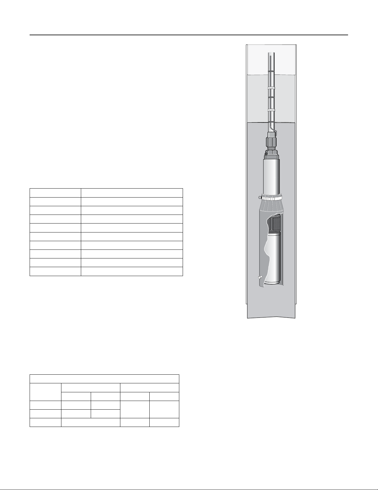
5.9 Motor Cooling
Pentek® 4” XE Series motors are designed to operate to a
maximum SF (Service Factor) horsepower in water up to
86° F (30° C).
4” motors: Minimum cooling water flow 3 HP and over
I.D of casing Flow GPM (LPM) required
4 1.2 (4.5
5 7 (26.5)
6 13 (49)
7 20 (76)
8 30 (114)
10 50 (189)
12 80 (303)
14 110 (416)
16 150 (568)
If the flow is less than specified, a flow-inducer sleeve
can be installed, as shown in Figure 5-2. The sleeve will
act like a smaller casing size to force flow around the
motor to aidcooling.
5.10 Starting Frequency
Recommended motor starting frequency is shown
below. Motor, pressure switch, tank, and pump life may
be extended by limiting starts per hour and starts per
day. Proper tank sizing is critical to control pump cycle
times. Excessive or rapid cycling creates heat which can
prematurely damage motors, switches, andcontrols.
Motor Starting Frequency
HP
1/2 thru 3/4 12.5 300
1 thru 5 4.2 100
7.5 thru 200 4.2 100
A one (1) minute minimum run time for pumps and motors up to 1.5HP and
two (2) minutes for 2HP and larger motors is recommended to dissipate heat
build-up from starting current.
24
Single Phase Three Phase
Starts/hr Starts/24hr Starts/hr Starts/24hr
12.5 300
Figure 5-2: Flow Inducer Sleeve

SECTION 6: Pentek® 6” Submersible Motors
6.1 Motor Inspection
Important Safety Instructions
SAVE THESE INSTRUCTIONS - This manual contains
important instructions that should be followed during
installation, operation, and maintenance.
This is the safety alert symbol. When you see this
symbol in this manual, look for one of the following
signal words and be alert to the potential for personal
injury!
indicates a hazard which, if not avoided, will
result in death or serious injury.
indicates a hazard which, if not avoided,
could result in death or serious injury.
indicates a hazard which, if not avoided,
could result in minor or moderate injury.
NOTICE
personalinjury.
Carefully read and follow all safety instructions in this
manual.
Keep safety labels in good condition. Replace missing
or damaged safety labels.
California Proposition 65 Warning
contain chemicals known to the State of California to
cause cancer, birth defects or other reproductive harm.
APPLICATION LIMITS
Maximum Immersion Depth: 985 ft. (300 m)
Maximum Water Temperature: 95°F (35°C)
pH content of the water: 6.5–8
Minimum Cooling Flow Rate: 0.5 feet per second (fps)
(0.15meters per second (mps)).
Required line voltage at the motor under operating
conditions (±10%).
NOTICE When calculating voltage at the motor, be sure
to allow for voltage drop in the cable.
The sum of the absolute values of the voltage and
frequency must not vary from the sum of the nominal
values by more than ±10%.
Operating with current unbalanced on the three legs of
the circuit can overheat and damage the motor and will
void the warranty. Current imbalance must not exceed
5% maximum.
Maximum Sand Content: 50ppm (max. size 0.1–0.25mm)
Maximum Chlorine Ion Content: 500ppm
addresses practices not related to
This product and related accessories
6.2 Testing
ELECTRICAL
(See Table 1, Page 4, for Motor Electrical
Specifications)
1. Risk of electrical shock if the cable is
damaged. Inspect the motor cable for any nicks or
cuts. Do not use the motor cable to pull, lift, or
handle the motor. Protect the motor cable during
storage, handling, moving, and installation of the
motor.
2. Inspect the motor to determine that it is the correct
horsepower, voltage, and size for the job and that
there is no shipping damage. Verify that the motor
nameplate voltage matches the available power
supply voltage. The nameplate rated voltage must
not vary more than ± 10% from the power supply
voltage.
3. On all new installations and after the motor has
sat idle for a long period of time, check the motor’s
internal electrical resistance with a megohmmeter
with lead wires connected. Prior to installation, the
motor should have an insulation value of at least
500 megohms. After installation, the motor and
power cable should have a minimum insulation
value of 1 megohm. If the minimum values are
below the listed values, contact the factory before
starting the motor.
4. Fuses or circuit breakers and overload protection
are required. Fuses or circuit breakers and
overloads must be sized in accordance with National
Electrical Code (NEC) or Canadian Electrical Code
(CEC) requirements, as applicable, and with all
applicable local codes and ordinances. See
Section 6 for these specifications.
5. Wire and ground the motor in accordance with
National Electrical Code (NEC) or Canadian
Electrical Code (CEC) requirements, as applicable,
and with all applicable local codes and ordinances.
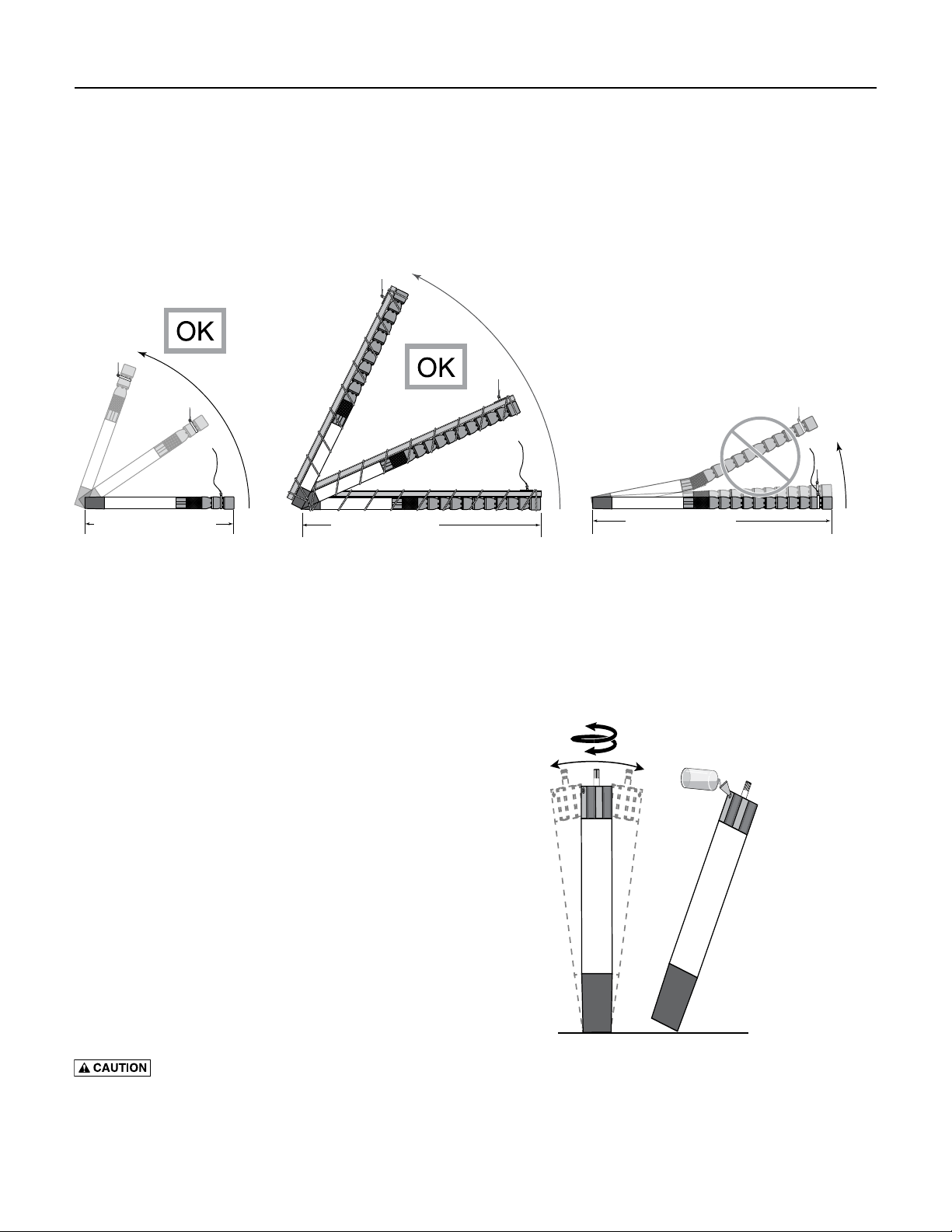
6.3 Storage and Drain/Fill Instructions
LIFTING
1. Heavy Object. Lifting equipment must be
capable of lifting motor and attached equipment. Check
over all tools, especially the hoisting gear, for wear or
damage before hoisting the unit.
2. If the total length of the pump and motor unit (without
any riser pipe attached) exceeds 10ft (3m), support the
unit with a girder while hoisting (see Figure 1). Do not
remove the supporting girder until the unit is standing
vertically in the hoist. Check for damage.
Pentek 6” Motors
25
SECTION 6: Pentek® 6” Submersible Motors
A. Rock motor
while turning
shaft.
B. Fill motor;
repeat rocking
and lling until
motor is full.
6.3 Storage and Drain/Fill Instructions
Figure 1: When the pump and motor together
(without any riser pipe) are 10ft (3m) long or more,
support the assembly before lifting to avoid bending
it in the middle. Never try to lift the motor or pump
by the motor cables.
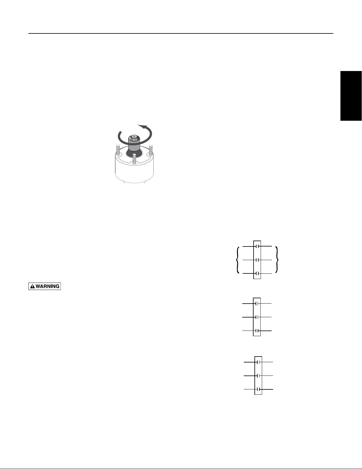
MOTOR STORAGE AND INSTALLATION
1. The motor is filled at the factory with anti-freeze
2. Verify that the motor is full before installing. If not, fill
from falling over.
Less Than 10 Ft (3 M)
which will protect it in temperatures down to –22ºF
(-30ºC). Do not install, transport or store the motor
below these temperatures if the motor is filled. If
storage is necessary at temperatures below –22ºF
(-30ºC), drain the anti-freeze from the motor.
it with clean water (see below). Installing a motor that
is not filled with liquid will void the warranty. Before
installation, check all water fill and drain plugs,
mounting bolts, and cable connections for tightness.
Refill the motor with clean water as follows:
A. Stand the motor on end (vertically) and remove the
fill plug with a 5mm hexagonal nut driver.
B. Turn the motor shaft by hand while rocking the
motor back and forth (see Figure 2).
C. Pour in clean water until the motor is as full as
possible.
D. Repeat the turning/rocking procedure.
E. Check the liquid level. If necessary, add more clean
water.
F. When the motor is full, re-install the fill plug.
Tighten it with the 5mm hexagonal nut driver.
Support motor while rocking to prevent motor
10 Ft (3M) or More
Support the pump and motor!
10 Ft (3M) or More
Lack of support will destroy the motor!
Figure 2: Rock Motor gently from side to side while
turning shaft by hand (A), then fill with clean water (B).
Repeat until full.
26
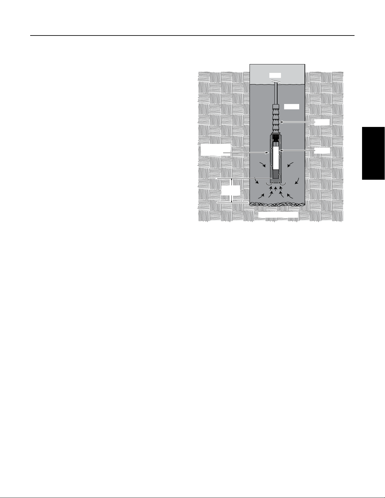
10’ (3M)
or more
Well
Water
Flow Inducer
Sleeve
Motor
Pump
NOT TO SCALE
SECTION 6: Pentek® 6” Submersible Motors
6.3 Storage and Drain/Fill Instructions
NOTICE To avoid damaging the motor thrust bearing,
do not hammer on the shaft, coupling, or slinger. Check
the motor rotation by hand to make sure that it turns
freely.
1. To avoid damage to the motor diaphragm, make
sure that the bottom of the motor does not touch
the dirt or mud at the bottom of the well. Install the
motor at least 10’ above the well bottom.
2. To install the motor horizontally, lay it down with
the lead wires at 12 o’clock when you are facing
the motor shaft. To prevent any load on the shaft
and bearings and to avoid any damaging vibrations
to the motor, mount the motor solidly on the pump
end and make sure that the pump and motor are
accurately aligned.
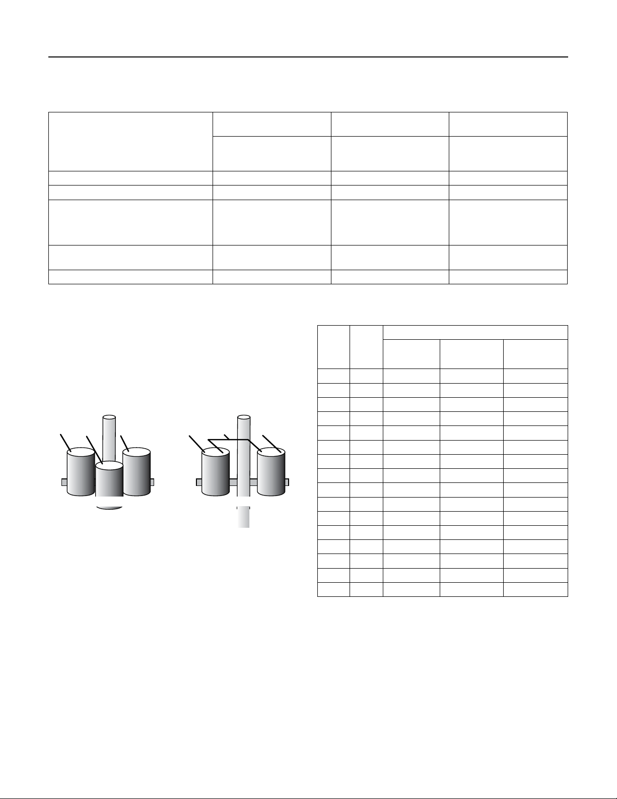
3. Install the motor so that during operation water
flows past all parts of it at a rate of at least 0.5 fps
(0.15 mps). If the well will not provide this flow,
install a sleeve on the motor to channel water past
it (see Figure 3). Do not try to operate the motor in
mud or sand. To do so will damage the motor and
void the warranty.
4. Electrical connections: Connect the three motor
leads to the three hot motor leads (black, brown,
and blue) in the incoming cable. Connect the
ground wire (green and yellow) in accordance with
NEC or CEC requirements (as applicable) and in
accordance with all applicable local codes and
ordinances. Apply power momentarily to check
rotation. If the motor runs backwards, interchange
any two power leads to reverse direction of rotation.
Figure 3: If flow past motor is less than .5 fps (0.15 mps),
install a flow inducer sleeve as shown. Flow must be at
least .5 fps (0.15 mps) for adequate motor cooling. The
flow inducer sleeve should not touch the
motor.
Pentek 6” Motors
side of the
27
SECTION 6: Pentek® 6” Submersible Motors
6.4 Motor Specifications
Ordering Information
MOTOR
TYPE PHASE NOTE
are 60 Hz
6” Three
Motors are
dual rated
50 Hz &
SERVICE FACTOR 1.00 SERVICE FACTOR 1.15
PENTEK
MODEL # HP KW HZ VOLTS
6PM2-5-2 5 4
6PM2-7-2 7-1/2 6 21.2 79 85 23.2 79 86 146.4 J 0.5389 3460 24.9 632 102 46
6PM2-10-2 10 8 30.8 77 81 33.0 78 83 187.6
Motors
6PM2-15-2 15 11 43.2 78 84 47.0 78 86 281.8 J 0.2782 3450 31.8 807.5 121 55
only
6MP2-20-2 20 15 57.4 79 85 63.0 79 87 394.5 J 0.2101 3450 35.1 892.5 147 67
6PM2-25-2 25 19 69 81 86 76.0 80 88 480.2 J 0.1605 3450 38.0 964.5 165 75
6PM2-30-2 30 22 76.6 84 88 85.0 84 89 614.2 K 0.1445 3500 41.8 1,060.5 190 86
6PM2-5-4 5 4
6PM2-7-4 7-1/2 6
6PM2-10-4 10 8
6PM2-15-4 15 11
6PM2-20-4 20 15
60 Hz
6MP2-25-4 25 19
6PM2-30-4 30 22
6PM2-40-4 40 30
6PM2-50-4 50 37
60 230
50 380 8.9 75 87 45.6
60 460 10.6 75 83 8.2 77 85 51.1 3460
50 380 12.5 79 87 66.8
60 460 15.4 79 85 11.6 79 86 73.2 3460
50 380 17.8 78 85 85.6
60 460 15.4 77 81 16.5 78 83 93.8 3440
50 380 25.6 77 87 127
60 460 21.6 78 84 23.5 78 86 140.9 3450
50 380 34 78 89 170.2
60 460 28.5 79 85 31.5 79 87 197.3 3450
50 380 41 79 89 219
60 460 34.5 81 86 38.0 80 88 240.1 3450
50 380 46 83 90 276.8
60 460 38 84 88 42.5 84 89 307.1 3500
50 380 62.5 83 90 393.1
60 460 52.7 84 88 58.0 84 89 439.7 3490
50 380 77.6 83 90 449.8
60 460 64.3 85 87 70.8 85 89 500.5 3480
EFF. %P.F.
AMPS
15 .2 75 83 16.4 77 85 102.1
% AMPS
EFF. %P.F.
LOCKED
ROTOR
THRUST
AMPS
% IN MM LBS KG
KVA
LOAD
CODE
K
1763
J 0.3964 3440 29.2 741.5 116 53
3485
K 2.9674
1763
J 1.9828
J 1.4648
J 0.9916
3485
J 0.7192
J 0.5640
K 0.5036
K 0.3958
6182
K .3295
INSULATION
CLASS
F
WINDING
LENGTH WEIGHT
RESISTANCE
(OHM) RPM
0.7873 3460 22.7 577 90 41
2820
22.7 577 90 41
2820
24.9 632 102 46
2800
29.2 741.5 116 53
2810
31.8 807.5 131 55
2810
35.1 892.5 147 67
2820
38.0 964.5 165 75
2880
41.8 1060.5 190 86
2860
47.1 1197 209 95
2840
49.9 1267 292 132
6.5 Motor Dimensions
D
28
L
1
Nominal diameter 6"/152.4 mm
Effective diameter 5.43"/138 mm
Shaft extension length 2.87" / 73 mm
L
For lengths, refer to Ordering Information tables.
Dimensions are for estimating purposes only.
SECTION 6: Pentek® 6” Submersible Motors
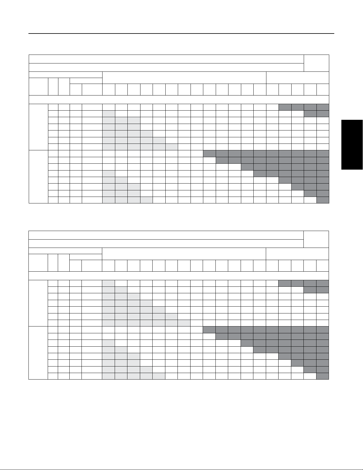
6.6 Motor Fuse Sizing and Cable Selection
CABLE SELECTION
COPPER CABLE SIZE - From Main Breaker Panel to Motor (in feet)
MOTOR
FUSE
VOLTS /
HZ HP KW
THREE PHASE
5 3.7 45 25 154 245 391 620 965 1538 1933 2442 3076 3883 4899 6184 7791 9198
7.5 5.5 60 40 - 174 277 438 682 1087 1367 1726 2174 2745 3463 4372 5508 6502 7806 9124
10 7.5 90 50 - - - 308 479 764 961 1213 1529 1930 2434 3073 3872 4571 5488 6415 7334 9125
230 V
15 11 125 80 - - - 216 337 537 675 852 1073 1355 1709 2158 2719 3210 3853 4504 5149 6407
60 Hz
20 15 175 110 - - - - 251 400 503 636 801 1011 1275 1610 2028 2394 2874 3360 3842 4780
25 18.5 225 125 - - - - - 332 417 527 664 838 1057 1334 1681 1985 2383 2785 3184 3962
30 22 250 125 - - - - - - 373 471 593 749 945 1193 1503 1775 2130 2490 2847 3543
5 3.7 20 10 617 982 1566 2480 3859 6152 7734 9767
7.5 5.5 30 20 436 694 1107 1753 2728 4349 5467 6904 8698
10 7.5 45 25 307 488 778 1233 1918 3057 3844 4854 6115 7719 9738
460 V
60 Hz
15 11 70 40 - 343 546 865 1347 2147 2699 3408 4293 5419 6837 8631
or
20 15 90 50 - - 408 646 1005 1601 2013 2543 3203 4043 5101 6439 8113 9578
380 V
50 Hz
25 18.5 110 60 - - - 535 833 1328 1669 2108 2655 3351 4228 5338 6725 7939 9531
30 22 125 70 - - - 479 745 1187 1492 1884 2374 2997 3781 4773 6013 7099 8522 9961
40 30 150 100 - - - - 546 870 1093 1381 1740 2196 2770 3497 4406 5202 6244 7299 8345
Lengths only meet the US National Electrical Code ampacity requirements for individual conductors rated 60° C in free air or water, NOT in magnetic enclosures, conduit or direct buried. Refer
to NEC Table 310.15(B)(17) for more information.
STD
Dual
Element
14 12 10 8 6 4 3 2 1 0 00 000 0000 250 300 350 400 500
AWG MCM
60˚
Pentek 6” Motors
CABLE SELECTION
COPPER CABLE SIZE - From Main Breaker Panel to Motor (in feet)
MOTOR
FUSE
VOLTS /
HZ HP KW
THREE PHASE
5 3.7 45 25 - 245 391 620 965 1538 1933 2442 3076 3883 4899 6184 7791 9198
7.5 5.5 60 40 - - 277 438 682 1087 1367 1726 2174 2745 3463 4372 5508 6502 7806 9124
10 7.5 90 50 - - - 308 479 764 961 1213 1529 1930 2434 3073 3872 4571 5488 6415 7334 9125
230 V
15 11 125 80 - - - - 337 537 675 852 1073 1355 1709 2158 2719 3210 3853 4504 5149 6407
60 Hz
20 15 175 110 - - - - - 400 503 636 801 1011 1275 1610 2028 2394 2874 3360 3842 4780
25 18.5 225 125 - - - - - - 417 527 664 838 1057 1334 1681 1985 2383 2785 3184 3962
30 22 250 125 - - - - - - - 471 593 749 945 1193 1503 1775 2130 2490 2847 3543
5 3.7 20 10 617 982 1566 2480 3859 6152 7734 9767
7.5 5.5 30 20 436 694 1107 1753 2728 4349 5467 6904 8698
10 7.5 45 25 - 488 778 1233 1918 3057 3844 4854 6115 7719 9738
460 V
60 Hz
15 11 70 40 - - 546 865 1347 2147 2699 3408 4293 5419 6837 8631
or
20 15 90 50 - - - 646 1005 1601 2013 2543 3203 4043 5101 6439 8113 9578
380 V
50 Hz
25 18.5 110 60 - - - 535 833 1328 1669 2108 2655 3351 4228 5338 6725 7939 9531
30 22 125 70 - - - - 745 1187 1492 1884 2374 2997 3781 4773 6013 7099 8522 9961
40 30 150 100 - - - - - 870 1093 1381 1740 2196 2770 3497 4406 5202 6244 7299 8345
Lengths only meet the US National Electrical Code ampacity requirements for individual conductors rated 75° C in free air or water, NOT in magnetic enclosures, conduit or direct buried. Refer
to NEC Table 310.15(B)(17) for more information.
STD
Dual
Element
14 12 10 8 6 4 3 2 1 0 00 000 0000 250 300 350 400 500
AWG MCM
75° C
29
 Loading...