

Page 1
EVERPURE® PRO
REVERSE OSMOSIS WATER FILTRATION SYSTEM
INSTALLATION AND OPERATING INSTRUCTIONS
©2014 Pentair Residential Filtration, LLC
Page 2
TABLE OF CONTENTS
WARNING:
Operating Specifications ...................................................... 2
System Dimensions .............................................................2
Production Capabilities........................................................2
Tools Required .....................................................................3
Precautions ..........................................................................3
How Reverse Osmosis Works .............................................. 4
Installation ..........................................................................5
System Startup ..................................................................11
Testing Your Reverse Osmosis System ..............................12
Maintenance .......................................................................12
Troubleshooting ................................................................. 14
Performance Data ..............................................................16
California Proposition 65 Warning .....................................17
Replacement Parts ............................................................18
NOTE: If your water pressure and temperature are at the
low end of the listed range (40 psi [2.8 bar] and 40°F
[4.4°C]), and the TDS level is near the maximum
(1500 ppm), the system will not function properly.
Under these extreme conditions, pre-warming the
supply water using a 25 feet (7.62 m) coil of tubing
between the supply adapter and the system, and/
or installing a booster pump to increase the water
pressure will allow the system to perform effectively.
Do not use with water that is microbiologically
unsafe or of unknown quality without adequate
disinfection before or after the system.
Systems certified for cyst reduction may be
used on disinfected waters that may contain
filterable cysts.
NOTE: Substances reduced are not necessarily in your
water. System must be maintained according to
manufacturer’s instructions, including replacement
of filter cartridges.
SYSTEM DIMENSIONS
OPERATING SPECIFICATIONS
IMPORTANT! Before installing this reverse osmosis system,
make certain your water supply complies with the following
operating specifications. Failure to comply may reduce the
effectiveness of the system and will void the warranty. Consult
your local water treatment utility or a certified water testing
lab to determine the quality for your water and use the table
below to record your results for future reference.
Specifications Your Water
Pressure Range: 40–100 psi
(2.7–6.9 bar)
Temperature
Range:
Total Dissolved
Solids: <1500 ppm
Maximum
Hardness †: 10gpg (171 mg/L)
Sulfide, Iron and
Manganese‡: <0.01 ppm
Chlorine in Water
Supply: <2 ppm
Water Supply pH
Limits: 4–11
Turbidity: 1 NTU Max
Model #
Date of Purchase:
†IMPORTANT: If the hardness of your water is above 10 gpg
(171 mg/L), lime scale will build up rapidly on the membrane
inside of the RO membrane cartridge. Scale buildup will plug
the RO membrane cartridge and make the system ineffective.
We do not recommend these reverse osmosis systems be used
with water in excess of 10 gpg (171 mg/L) hardness, unless the
water is softened prior to the reverse osmosis system.
‡See your local dealer or water treatment specialist to reduce
these substances in your water.
40–100°F
(4.4–37.8°C)
System Dimensions: 13.75 inches W x 4.75 inches D x
12.75 inches H
(349 mm x 121 mm x 318 mm)
System Weight: 6.1 lbs. (2.7 kg)
Tank Dimensions: 11.3 inches Dia x 16.75 inches H
(287 mm x 425 mm) (with valve)
Tank Capacity: 1.9–3.2 gallons (7.2–12.1 L)
(depending on water pressure)
Tank Weight (full): 40 lbs. (18.2 kg.)
(depending on water pressure)
PRODUCTION CAPABILITIES
Tested by NSF International according to NSF/ANSI Standard 58
has given 5.7 gallons per day. Source water test parameters are
50 psig, 77ºF, pH of 7.5 ± 0.5 and 750 ppm total dissolved solids.
The PRO is Tested and Certified by NSF
International against NSF/ANSI Standard 58 for
the reduction of Total Dissolved Solids, Fluoride,
Turbidity, Nitrate/Nitrite, Lead, Selenium,
Pentavalent Arsenic, Copper, Cadmium,
Hexavalant Chromium, Trivalent Chromium,
Barium, Cysts, Radium 226/228 and NSF/ANSI
Standard 42 for the reduction of chlorine taste
and Odor.
NSF ANSI Standard 58 certified to reduce cysts such
as Cryptosporidium and Giardia by mechanical means.
EPA Est. No 090375-MEX-001
2 • EVERPURE
®
PRO-Reverse Osmosis Water Filtration System Installation and Operating Instructions
Page 3

TOOLS REQUIRED
WARNING:
CAUTION
CAUTION
Tools Required
• Hand or electric drill
• Screwdriver - Phillips
• (2) Adjustable wrenches
• Drill bits: 1/8-inch, 1/4-inch and 3/8-inch
• Metal file
• Safety glasses
• Utility knife or tube cutter
• Needle-nose pliers
• Measuring tape
If sink does not have hole for separate faucet:
• Center punch
• 1-1/4 inch bi-metal or carbide-tipped hole saw
• Respirator
NOTE: All tools listed will not be necessary for installation.
Read installation procedures before starting to
determine required tools.
PRECAUTIONS
The PRO system contains a replaceable
membrane critical to the efficiency of the
system. Replacement of the reverse osmosis
membrane should be with one of identical
specifications, as defined by the manufacturer,
to assure the same efficiency and contaminant
reduction performance.
The PRO system contains a replaceable
The PRO is acceptable for treatment of
The PRO shall only be used for arsenic
The Reverse Osmosis (RO) system will not
Because of the product’s limited service life and to
Do not use Plumber’s Putty in the installation of
NOTE:
membrane, critical for the effective reduction
of total dissolved solids. Product water should
be tested periodically to verify that the system
is working properly.
influent concentrations of no more than 27
mg/L nitrate and 3 mg/L nitrite in combination
measured as N and is certified for nitrate/
nitrite reduction only for water supplies with
a pressure of 40 psig (280 kPa) or greater.
reduction on chlorinated water supplies
containing detectable residual free chlorine at
the system inlet. Water systems using an inline chlorinator should provide a one-minute
chlorine contact time before the RO system.
protect against disease-causing bacteria or
remove naturally-occurring harmless bacteria.
The PRO system must be protected against
freezing which can cause the filter housing to
crack and leak water.
prevent costly repairs or possible water damage,
we strongly recommend that the filter housings be
replaced every ten years. If your housing has been in
use for longer than this period, it should be replaced
immediately. Date the bottom of any new filter
housing to recommend the next replacement date.
this product as it may cause cracking of the filter
housing threads.
EVERPURE
®
PRO-Reverse Osmosis Water Filtration System Installation and Operating Instructions • 3
• Your water must be within required limits for
satisfactory operation. If not, your membrane life may
be shortened and your warranty will be voided (see
Operating Specifications, page 1).
• Install on cold water line only.
• Make certain that installation complies with all state
and local laws and regulations.
• The reverse osmosis membrane and replacement
cartridges included with this system have limited
service lives. Changes in taste, odor, and color of the
filtered water indicate that the cartridge(s) and/or
membrane should be replaced (see Maintenance, page
10). On the monitored model (PRO) the green light
indicates optimum performance while the amber light
indicates that the membrane is in need of changing.
• During extended periods of non-use (such as during a
vacation), remove the membrane from the membrane
housing and place it in a sealed plastic bag. Store
membrane in refrigerator for future use. DO
NOT FREEZE.
• If system stands for more than 2–3 days without being
used, the storage tank should be emptied.
Membrane Precautions
Chlorine will destroy the Reverse Osmosis
membrane. If you use these RO systems with a
chlorinated or periodically-chlorinated water
supply, it is ABSOLUTELY NECESSARY to use a
carbon prefilter (included with the system). This
carbon prefilter should be changed at least every
3 months to avoid chlorine breakthrough. See
warranty for disclaimers and limitations that apply
to the RO membrane.
NOTE: To make sure no chlorine is present in the water that
reaches the membrane, use a test kit that tests
free-chlorine to check the reject water that flows
from the membrane to the drain. No chlorine should
be detected.
Page 4

HOW REVERSE OSMOSIS WORKS
The Everpure PRO uses a semi-permeable membrane to
reduce dissolved salts, improving the taste and odor of your
water. The RO membrane is made of multiple layers of
micron-thin film wound around a hollow center core. Water
molecules can pass through the membrane, while dissolved
salts are rejected.
The Everpure PRO system features triple-filter action. Your
household water supply is prefiltered to reduce dirt and
chlorine that may foul the membrane. The RO membrane
separates this prefiltered water into PRODUCT WATER and
REJECT WATER. Your household water pressure forces the
product water through the membrane and into the storage
tank. Dissolved salts cannot pass through the membrane and
are sent to the drain as reject water. When you open the RO
faucet, product water is drawn from the storage tank through
a post-polishing filter. The post-polishing filter takes out any
remaining taste or odor in the water and provides you and your
family with cleaner, great-tasting water.
The PRO system also features an auto shut-off valve, which
shuts off the system once the pressure in the storage tank
reaches 2/3 of the incoming water pressure (your household
water pressure). When you open the faucet to draw water from
the storage tank, the pressure inside the tank drops and the
auto shut-off valve opens. The system then begins to operate,
replenishing the water you took from the storage tank. For
each gallon of water produced, 9 gallons are discharged as
reject water. The storage tank can hold up to
3.2 gallons of water at a time, more than enough for the
average family’s drinking and cooking needs.
When used under operating conditions specified on page 2 of
the manual, your Reverse Osmosis membranes should last
12–24 months.
NOTE: The PRO unit will indicate a need for a membrane
The precise life span of your system’s membrane will depend
on the quality of the water entering the system and the
frequency with which you use it. Frequent use prevents the
dissolved salts from building up on the membrane as scale.
The more water the system is required to produce, the longer
the membrane will last. You may wish to find a variety of uses
for your system in order to prolong the life of the membrane.
The life of the membrane will also depend upon the regularity
with which you replace the prefilter cartridge in the system.
change with an amber light; see LIGHT INDICATOR
READINGs, page 10 for details.
4 • EVERPURE
®
PRO-Reverse Osmosis Water Filtration System Installation and Operating Instructions
Page 5
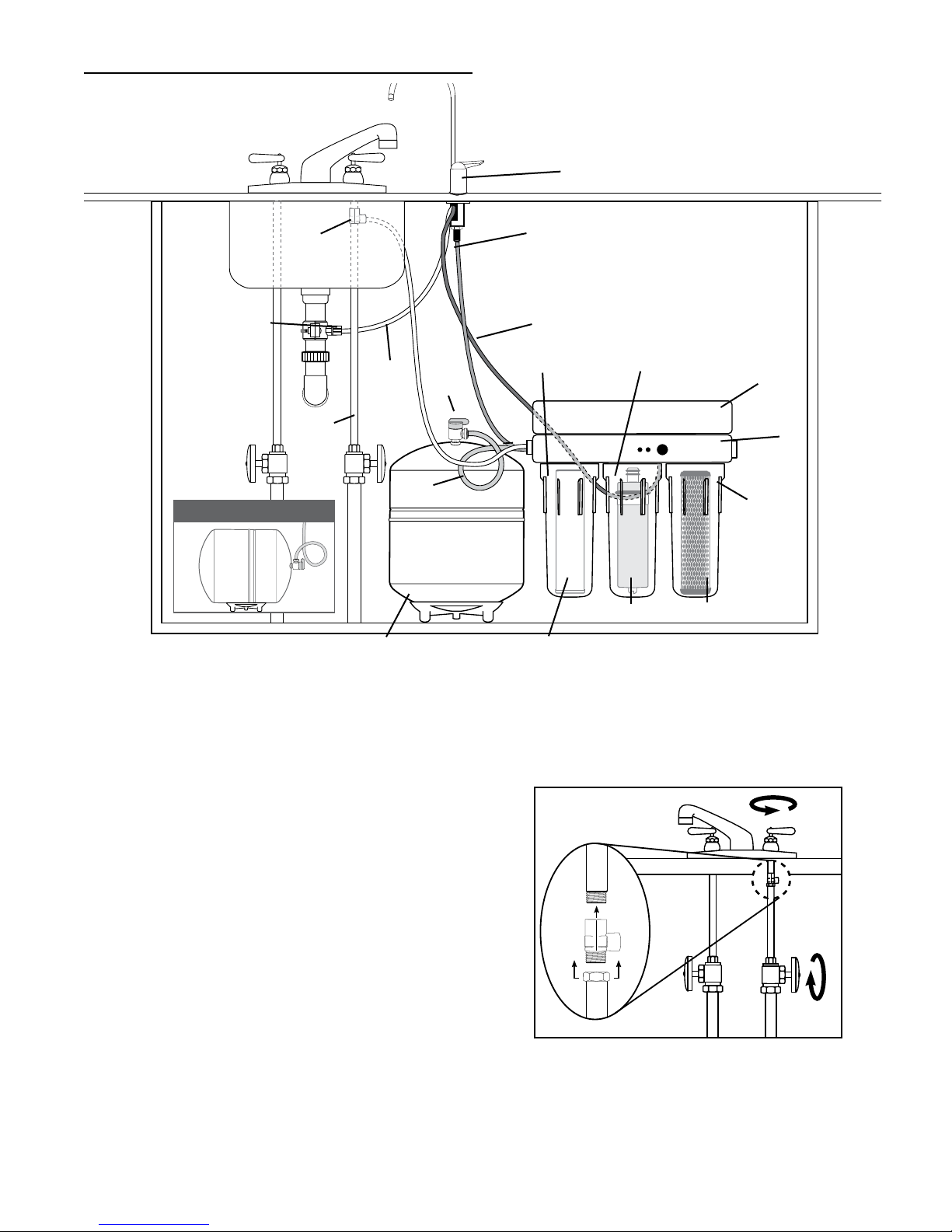
INSTALLATION
Drinking Water Faucet
Supply
Adapter
Drain
Clamp
Cold
Water
Optional Tank Installation
White
Green
Storage
Tank
Tank
Valve
Blue
Red
Post-polishing
Filter Housing
Post-polishing
Filter
Membrane
Housing
Membrane
Manifold
Cover
Manifold
Prefilter
Housing
Prefilter
Figure 1
Installing the Water Supply Adapter
NOTE: Read all installation and operating instructions
before installing and using your RO system.
The supply adapter fits 1/2-NPS supply threads. If local codes
permit, it may be used to connect the PRO to the cold water
supply line. If local codes do not permit the use of the supply
adapter, alternate connectors can be obtained from your local
plumbing wholesaler.
See Figure 2.
1. Turn off cold water supply line. If cold water line does not
have a shut-off valve under the sink, you should install one.
2. Turn on the cold water faucet and allow all water to drain
from line.
3. Disconnect cold water line from the threaded stub on
bottom of main faucet.
4. Apply plumber tape onto threads of faucet stub and supply
adapter. Screw the water supply adapter to the threaded
faucet stub as shown.
5. Using the nut that previously connected the cold water line
to the faucet, screw the cold water line to the male supply
adapter threads.
Figure 2
EVERPURE
®
PRO-Reverse Osmosis Water Filtration System Installation and Operating Instructions • 5
Page 6
Selecting the Faucet Location
CAUTION
The drinking water faucet should be positioned with function,
convenience and appearance in mind. An adequate flat area is
required to allow faucet base to rest securely. The faucet fits
through a 1-1/4 inch hole. Most sinks have pre-drilled
1-1/2 inch or 1-3/8 inch diameter holes designed for spray
hoses. The drinking water faucet may be installed using one of
these holes, despite their larger size. If these pre-drilled holes
cannot be used or are in an inconvenient location, it will be
necessary to drill a 1-1/4 inch hole for the faucet in the sink or
through the countertop next to the sink.
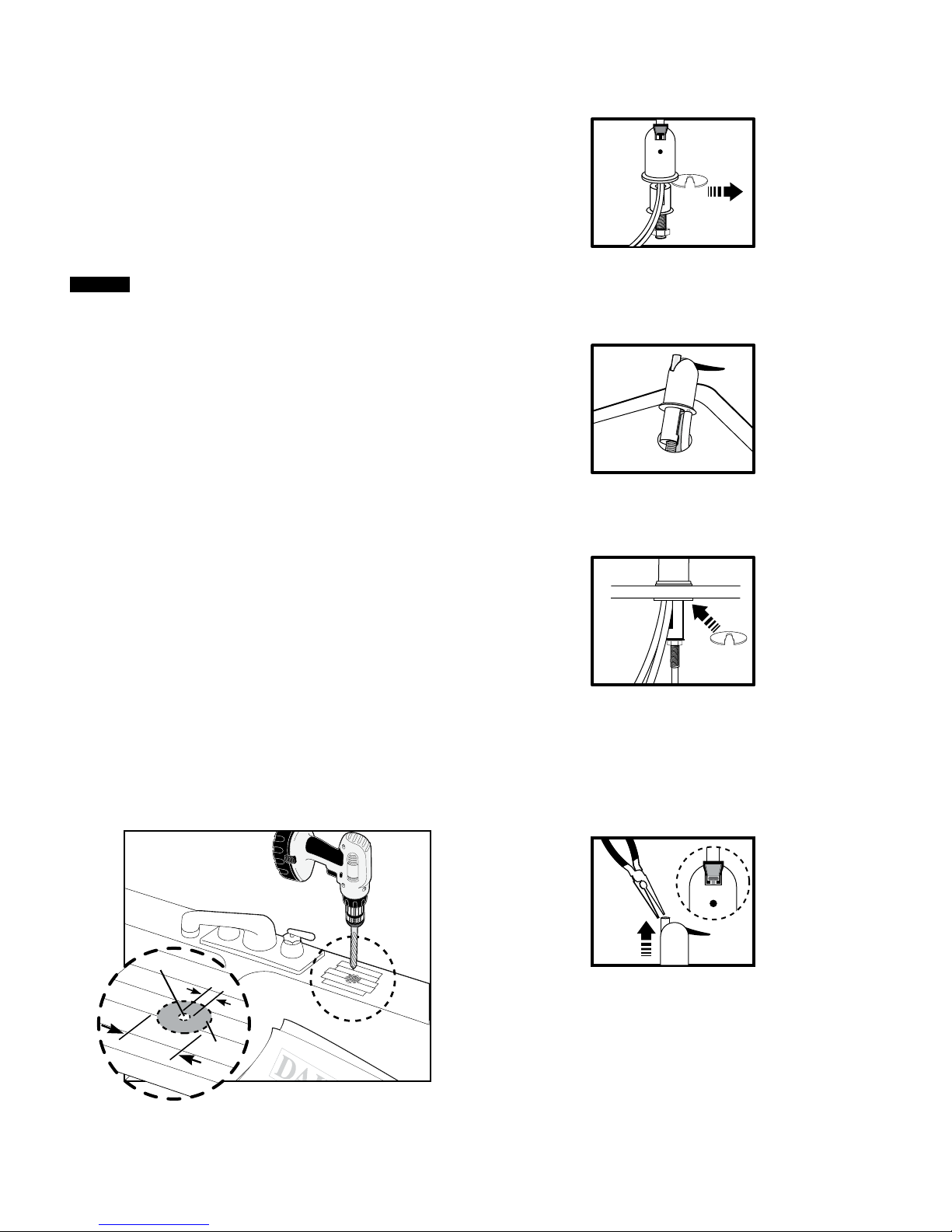
Mounting the Faucet
1. Loosen brass stem-nut on faucet, remove metal “C”
disc (Figure 4).
Drilling the Faucet Hole
This procedure may generate dusts which can
cause severe irritation if inhaled or if they come
into contact with the eyes. The use of safety
glasses and respirator for this procedure
is recommended.
DO NOT ATTEMPT TO DRILL THROUGH AN ALL-
PORCELAIN OR PORCELAIN-COATED SINK. For
applications on these types of sinks we recommend
using the sprayer hole or mounting the faucet
through the countertop.
When drilling through a countertop make sure the
area below the drilled area is free of wiring and
piping. Make certain that you have ample room to
make the proper connections to the bottom of
the faucet.
Do not drill through a countertop that is more than
1-inch thick.
Do not attempt to drill through a tiled, marble,
granite or similar countertop. Consult a plumber
or the countertop manufacturer for advice
or assistance.
The following instructions apply to stainless steel sinks only.
See Figure 3.
1. Line bottom of sink with newspaper to prevent shavings,
parts or tools from falling down the drain.
2. Place masking tape over the area to be drilled to help
prevent scratches if drill bit slips.
3. Mark point with center punch. Use a 1/4-inch drill bit to
drill a pilot hole through sink.
4. Use a 1-1/4 inch hole saw to enlarge hole. Smooth rough
edges with a file.
Figure 4
2. Holding the faucet, feed the three tubes through the hole in
the sink. Position the faucet handle at the desired
location (Figure 5).
Figure 5
3. Center the faucet and slip “C” disc between the white
spacer and the bottom of the counter or sink. Tighten the
stem nut with a wrench until it is tight (Figure 6).
Figure 6
4. Making sure the faucet handle is in the down position, use
a needle-nose pliers to pull the short plastic tube out of
the top of the faucet base (Figure 7).
NOTE: If handle should come off faucet base, make sure the
T-Bar is parallel to the front of the faucet base before
inserting handle. If T-Bar is not in the correct position
the faucet will not work properly.
Pilot Hole
1/4"
1-1/4"
Mounting
Hole
Figure 3
6 • EVERPURE
®
PRO-Reverse Osmosis Water Filtration System Installation and Operating Instructions
Figure 7
Page 7

5. Lubricate the o-rings on the bottom of the faucet spout
with supplied silicone lubricant. Use lubricant
sparingly (Figure 8).
Figure 8
6. Insert goose-neck spout into faucet base firmly (Figure 9).
Figure 9
Installing the Drain Clamp
NOTE: If you have a single-basin sink with a disposal unit,
call Technical Support at 1-800-279-9404 for options.
NOTE: Before installing the drain clamp, check the drain
pipes under the sink for corrosion. Corroded pipes
should be replaced before continuing with
the installation.
1. Attach the drain clamp to a vertical section of the
drainpipe, about 6 inches above the trap. Make sure the
opening on the drain clamp is facing towards the drinking
water faucet (Figure 10).
3. Remove the drain clamp from the drainpipe and enlarge
the hole with a 3/8-inch drill bit (Figure 12). Use a file to
remove rough edges from the drilled hole.
Figure 12
4. Make sure the black rubber gasket is adhered to the inside
of the drain clamp and place the drain clamp assembly
over the drilled hole. Look through the hole and position
the clamp so that the center of the clamp hole is slightly
higher (about 1/16 inch) than the center of the drilled hole.
(Figure 13). Tighten the clamp securely.
Figure 13
5. Screw the plastic compression nut onto the drain clamp
until hand-tight (Figure 14).
Figure 10
2. Using the fitting hole of the drain clamp as a guide, drill a
1/4-inch hole through one side of the drain pipe (Figure 11).
Figure 11
EVERPURE
6 inches
Figure 14
®
PRO-Reverse Osmosis Water Filtration System Installation and Operating Instructions • 7
Page 8

Connecting the Faucet to the Drain
CAUTION
NOTE: This is a gravity drain line. Any loops, kinks or sharp
bends must be eliminated before proceeding. Failure
to create a straight line to the drain may result in
reject water leaking through the air gap in the faucet
onto the counter top and below the faucet.
1. Align the white 3/8-inch tubing from the faucet with the
compression nut on the drain clamp. Create as straight a path
as possible with the tubing. Cut the tubing squarely below the
nut and remove the internal and external burrs (Figure 15).
Figure 15
2. Loosen the compression nut two complete turns. Insert the
tubing into the nut until it stops. Tighten with fingers, then
tighten 1 to 2 turns with a wrench (Figure 16).
Installation of Mounting Screws
When tank is full, it weighs approximately 40
pounds. Provide ample support under the tank.
If system is being installed under the kitchen sink, locate it
on back or right side wall. Make sure to allow ample space
for installation. To change the filter cartridges, a minimum
of 1-1/2 inches of clearance is required underneath the filter
housings. A minimum of 2 inches of clearance from the left
side of the unit is also required or 6 inches from the left
bracket mounting screw hole.
Install mounting screws at least 13-3/4 inches from cabinet
floor and 5-3/8 inches apart. Leave a 5/16 inch space between
the head of the screw and the wall to slip bracket onto screws.
Figure 16
Figure 17
8 • EVERPURE
®
PRO-Reverse Osmosis Water Filtration System Installation and Operating Instructions
Page 9

Connecting the Faucet to the System
CAUTION
CAUTION
1. Locate the red tubing (reject water line) from the drinking
water faucet. Place a mark on the red tubing 5/8 inch from
the end. Moisten the end of the tubing with water and insert
tubing into the red quick-connect fitting found behind the
membrane (middle) housing. Insert tubing until the mark is
flush with the quick-connect opening (Figure 18).
Red quick-connect fitting
Figure 18
2. If desired, use the 1/4-inch elbow included with the
installation kit. This elbow can be pressed in for installations
in situations where room is not available to bend the tubing.
This elbow fitting can also be swiveled. Locate the 1/4-inch
fitting with the blue quick-connect collar on the left hand
side of the RO system. Align the blue tubing from the faucet
with the quick-connect fitting on the RO system. Place a
mark on the blue tubing 5/8-inch from the end. Moisten the
end of the tubing with water and insert until the mark is
flush with the quick-connect opening (Figure 19).
If tubing is not firmly connected, leaking will occur. It is
important for the tubing to be inserted all the way until the
mark is flush with the outer edge of the quick-connect insert.
NOTE: Tubing may be quickly and easily removed from the
fitting if necessary by pressing the collar around the
fitting while pulling the tubing with your other hand.
Connecting the Storage Tank to the System
When tank is full, it weighs approximately 40 lbs.
Provide ample support under the tank.
1. Remove the black protective cap to expose the 1/4-inch
threaded opening at the top of the tank (Figure 20).
2. Thread the tank valve onto the top of the tank opening by
turning it clockwise until snug.
3. Locate the green tubing. Place a mark on the green tubing
3/4 inch from each end. Moisten one end of the green
tubing with water and insert with a twisting motion into the
free port of the tank valve until the 3/4-inch mark is flush
with the quick-connect fitting (Figure 20).
Figure 20
4. Install free end of green tubing to green quick-connect
fitting or elbow as directed in Figure 21.
NOTE: Do not cut green tube. This line should be left at the
pre-cut length for future service.
Without
elbow
5/8"
Figure 19
With
elbow
5/8"
Figure 21
5. Place entire system over mounting screws on wall and
slide down.
Make certain system is firmly attached to wall to
prevent it from falling and possibly
becoming damaged.
NOTE: Use caution not to bend or pinch the tubing behind
the system while attaching to mounting screws.
NOTE: The pressurized storage tank has a capacity of
1.9–3.2 gallons. The tank’s air pressure is factory set
at 5–7 psi when tank is empty.
EVERPURE
®
PRO-Reverse Osmosis Water Filtration System Installation and Operating Instructions • 9
Page 10

Connecting the Supply Adapter and Inlet of Filter
CAUTION
See Figure 22.
1. Locate the pre-installed white plastic tubing on the lefthand side of the RO system. Place a mark 5/8 inch from the
end of the tubing.
2. Wet tubing with water and insert into supply adapter 5/8
inch until mark is flush with fitting.
NOTE: Disconnecting the tubing from the
Quick-Connect Fittings.
Routine maintenance and cartridge replacement will not
require that you disconnect the tubing from the filter system;
however, tubing may be quickly and easily removed from the
fitting if necessary. First, turn off the water supply to the filter.
Open faucet, then press in the gray collar around the fitting
while pulling the tubing with your other hand.
5/8-inch
(16mm)
Locking
Device
Membrane
O-rings
Brine
Housing
Seal
O-ring
Brine-
ring
o-rings
Figure 23
Faucet Operation
For controlled water flow, push the handle down. For constant
water flow, lift the faucet handle to lock it in the open position
(Figure 24).
Figure 22
Installing the Membrane
See Figure 23.
1. Using the housing wrench, unscrew the middle
(membrane) housing.
NOTE: Do not unwrap the tape around the membrane;
it is part of the membrane. Do not squeeze the
membrane.
2. Turn locking device clockwise to remove. Grasp the
membrane by the central tube (the end with the two
o-rings). Before insertion, lightly lubricate the brine seal
with the silicone lubricant (included with membrane).
3. Gently slide the membrane into the housing. Pressing on
the central tube of the membrane from the top only, push
the membrane fully into the housing until the central
tube is flush with the top of the housing. Be sure to push
the membrane straight down into the housing. If the
membrane is not centered in the housing, the locking
device will not fit properly. After the membrane is seated,
lightly lubricate the membrane o-rings with a small
amount of the silicone lubricant.
4. Insert, and turn the locking device counterclockwise. Screw
the housing back onto the RO system until it is hand-tight.
DO NOT OVER TIGHTEN.
The housing o-ring provides the watertight seal
between the cap and the housing. It is important
that the o-ring be properly seated in the groove
below the threads of the housing or a water leak
could occur.
Controlled
water flow
Constant
water flow
Figure 24
Battery Installation
1. Remove manifold cover.
2. Plug battery into leads.
3. Place battery in holder at the front of unit and replace cover.
10 • EVERPURE
®
PRO-Reverse Osmosis Water Filtration System Installation and Operating Instructions
Page 11

SYSTEM STARTUP
CAUTION
CAUTION
CAUTION
NOTE: The reverse osmosis membrane is treated with a food
grade sanitizing agent that may cause an undesirable
taste. Although it is not harmful, it should be flushed
from the system.
The post-polishing filter may contain fine black
carbon particles. These fines are harmless, but may
make the water appear gray in color. The carbon
fines are flushed from the system with the first tank
full of water.
The RO system does not produce a high volume of
water on demand as an ordinary filter does. Water is
produced at a slow, drop-by-drop rate. The system
requires about 6–12 hours to fill the storage tank. As
water is taken from the tank, the system automatically
starts the cycle of replacing the water and then stops
water production when the tank is full.
Visually check the entire system for leaks. Remove
the manifold cover and check the top of the
manifold for leaks. If a leak is present,
see TROUBLESHOOTING.
1. Turn off valve at top of storage tank (Figure 25).
2. Turn on the cold water supply (Figure 25).
Closed Tank Valve
Open Tank Valve
Figure 25
3. Lift the faucet handle to lock it in the open position and let
it drip for 30 minutes.
NOTE: If the test button is pushed during the first 30
minutes of flushing, you may get an amber rather
than a green light indication. This is due to the
disinfectant agent being flushed from the membrane
and is not a problem.
4. Turn off cold water supply and wait for the faucet to stop
dripping. Place a tray under the system and remove the left
(post-polishing) filter housing. Dump the water from the
housing into the sink and insert the white post-polishing
filter with the black gasket end facing up. Check the
housing o-ring to make sure it is properly seated and screw
the housing back onto the manifold. HAND TIGHTEN ONLY.
5. Completely open the cold water supply until it comes to a
stop. Allow water to drip from the faucet for 3 more hours.
Then close the faucet and open the valve on the storage
tank. The tank valve is open when the handle lines up with
the tubing connection.
6. Allow 6–12 hours for the tank to fill. Periodically check
the installation for leaks. After the storage tank is filled,
open the faucet to flush the post-polishing filter. Allow 4–5
minutes for all of the water to drain from the tank.
7. Close faucet and allow tank to fill.
NOTE: Initially, the water may appear cloudy. This is a result
of air trapped in the post-polishing filter. It is not
harmful and will disappear in a matter of minutes. It
may take up to a week after installing a new postpolishing filter for the trapped air to dissipate.
The system is ready for operation. You can now enjoy quality
water from your Reverse Osmosis system.
Connecting your Reverse Osmosis System to
Refrigerator Icemaker / Water Dispenser
If you are connecting this unit to your refrigerator/
icemaker with initial RO installation, wait to turn
on the icemaker until the post-polishing filter has
been flushed according to step 6 in
SYSTEM STARTUP.
Use plastic tubing and fittings. Do not use copper
tubing or brass fittings.
NOTE: For optimum performance, it is recommended
that the distance between the RO system and the
refrigerator icemaker/water dispenser be no greater
than 10 feet (3 m). At distances greater than 10 feet,
the water pressure from the system may not be
adequate to deliver water to the refrigerator.
Materials Required
(available from your local hardware store)
• Shut-off valve
• 1/4-inch (0.635 cm) polyethylene tubing
(maximum length of 10 feet (3m) recommended)
• 1/4-inch x 1/4-inch x 1/4-inch (0.635 cm x 0.635 cm x
0.635 cm) compression or quick-connect tee
1. Turn off refrigerator water supply and icemaker. Consult
manufacturer’s guidelines.
2. Close tank valve (on top of storage tank).
3. Turn off water to RO system at the cold water supply.
4. Open drinking water faucet to relieve pressure.
5. Locate blue tubing leading to your drinking water
faucet. Cut and insert the 1/4-inch x 1/4-inch x 1/4-inch
compression or quick-connect tee into the blue tubing.
Consult manufacturer’s guidelines before installing the
supply adapter.
NOTE: When cutting this blue tubing, you may experience
some water leakage.
6. Using a length of 1/4-inch polyethylene tubing, connect
the icemaker/dispenser line with the free port on the
compression tee.
7. The shut-off valve should be installed as close to this port
of the tee as possible. Shut-off valve should be installed in
the OFF position. Consult manufacturer’s guidelines before
installing the shut-off valve.
8. Completely open cold water supply (until it comes to a stop).
9. Open tank valve.
10. Turn off the drinking water faucet.
11. Open shut-off valve at the supply adapter.
12. Turn on icemaker. Consult manufacturer’s instructions.
13. Check for leaks and tighten connections if necessary.
EVERPURE
®
PRO-Reverse Osmosis Water Filtration System Installation and Operating Instructions • 11
Page 12

TESTING YOUR REVERSE OSMOSIS SYSTEM
WARNING:
CAUTION
Dissolved Solids (TDS) Test
NOTE: Under NSF/ANSI Standard 58, it is highly
recommended that you (the consumer) have your
water tested at least every 6 months to verify that
your system is performing satisfactorily.
PRO Monitored Reverse Osmosis System
Light Indicator Readings on the PRO
The PRO is equipped with a monitor (Figure 26) that checks the
Total Dissolved Solids (TDS) that the system is reducing. This
allows the user to see the quality of the water that the system
is producing. Test the unit monthly. When the blue test button
is pushed, the light system will read one of the following colors:
Green light: Good Water
Amber light: If this is a new installation, call Technical
Support. Otherwise, draw 1 gallon of water
from the unit. After 10 minutes, push the
button to test. If the light is still amber,
change the prefilter and empty the tank. If
the light is still amber after 1 hour, you may
need to replace the membrane. Determine
when you last changed the membrane and
call Technical Support at 1-800-863-9392.
No light: The battery needs to be changed.
Figure 26
Nitrate Test Kit
A Nitrate Test Kit is included with this unit and is designed
to indicate nitrate levels in the drinking water. Test the water
monthly. The current EPA Maximum Contaminant Level
(MCL) for Nitrate as Nitrogen (N) is 10 mg/L or 10 ppm. The
current EPA maximum contaminant level (MCL)for Nitrite as
Nitrogen (N) is 1 mg/L or 1 ppm. Results showing any nitrate
breakthrough should be followed up with a laboratory analysis
of the water.
Consult with your doctor to see if you should
drink water with the nitrate/nitrite levels
found in your water.
Nitrate Test Kit
MAINTENANCE
Use only the replacement elements and parts referred to in
this manual. Failing to do so will void your warranty.
NOTE: Use a different sink or set aside water to wash and
rinse housings. Read appropriate instructions to
determine amount of water required.
Replacing the Prefilter and Post-polishing Filter
Cartridges
Replacement Filter Cartridges
The Gray/Black Prefilter Cartridge (D-15) should be replaced
every 3 months, or earlier if your water is highly turbid, and
when changing the membrane.
The White Post-polishing Filter Cartridge (D-20) should be
replaced at least every 12 months and when changing the
membrane.
Materials Required
• PRO Replacement
Cartridge Kit
• FDA-Grade silicone grease
• Clean washcloth
• Non-abrasive brush or sponge
• Clean rubber gloves (optional)
• Dishwashing soap
Replacing the Filter Cartridges
1. Close cold water supply and place a tray under the system
to catch any water that spills during removal of the filter
housings. If an icemaker is attached to the unit, turn it off and
also the shut-off valve found at the 1/4-inch supply adapter.
2. Lift the faucet handle to lock it in the open position.
3. After water flow from the faucet stops, unscrew the filter
housing from the left and/or right side of the manifold. Do
not remove the membrane (center) housing. Discard
used cartridges.
NOTE: Use clean rubber gloves or wash hands
thoroughly for this procedure to avoid
contaminating the cleaning solution or any of the
components of the system. It is recommended
that clean rubber gloves be worn when cleaning
and/or sanitizing the system and its components
or handling new filter cartridges.
4. Locate and remove o-ring from grooves in the sump. Wipe
grooves and o-ring clean of old lubricant and set aside.
Rinse out bottom of sump and fill 1/3 full with water. Add
1 tablespoon of bleach and scrub cap and bottom of sump
with non-abrasive sponge or cloth. Rinse thoroughly.
5. Inspect the o-ring for damage (i.e. nicks, scratches) and
replace damaged o-rings. See REPLACEMENT PARTS for
reorder information and part numbers
NOTE: Do not get any of the electronic circuits or wiring
wet when cleaning the unit.
6. Lightly lubricate the o-ring with a coating of clean silicone
grease. With two fingers, press o-ring securely into groove
below the threads of the housing.
Figure 27
Testing Instructions:
Testing instructions are included with the Nitrate Test Kit
(Figure 27). If the Nitrate Test Kit is missing, please call
1-800-279-9404 for replacement.
12 • EVERPURE
®
PRO-Reverse Osmosis Water Filtration System Installation and Operating Instructions
The housing o-ring provides the water-tight seal
between the cap and the bottom of the housing. It
is important that the o-ring be properly seated in
the groove below the threads of the housing or a
water leak could occur.
Page 13

7. Insert the new cartridge into the housing. Make sure the
CAUTION
CAUTION
CAUTION
CAUTION
cartridge slips over the standpipe in the bottom of the
housing.
NOTE: Be sure to install cartridges in proper
housings (Figure 1).
8. Screw the housing back onto the manifold.
HAND-TIGHTEN ONLY.
9. Slowly open the cold water supply until it comes to a stop.
Check for leaks.
10. Let water drip from drinking water faucet for 3 hours.
Continue to periodically check for leaks.
11. Close faucet and wait 6–12 hours to allow the tank to fill.
Open the drinking water faucet and drain one full tank to
flush the carbon fines out of the system.
12. If the unit is attached to an icemaker, wait one hour before
turning on the icemaker.
Replacing the Reverse Osmosis Membrane
Replacement Filter Cartridges
The Gray/Black Prefilter Cartridge and the White
Post-polishing Filter Cartridge should be replaced when
changing the membrane. See Materials Required below.
Materials Required
• PRO Replacement Cartridge Kit
• New membrane:
PRO_RM Membrane
• Clean rubber gloves
• Clean washcloth
• Dishwashing soap
• Chlorine bleach
• FDA-Grade silicone grease
• Needle-nose pliers
• Safety glasses
• Large bucket
• 9-volt battery
• Non-abrasive brush or sponge
The Membrane (PRO) should be replaced every 12–24 months.
NOTE: When handling the membrane, do not squeeze it, as
this will damage the membrane’s effectiveness.
NOTE: It is recommended that you sanitize the system each
time you change the membrane. It is not necessary to
sanitize the system when changing only the prefilter
or post-polishing filter cartridges.
NOTE: When installing a new membrane, it is recommended
that you also replace the prefilter and post-polishing
filter cartridges.
Removing the Filter Cartridges and Membrane
1. Turn off cold water supply. Place a tray under the system to
catch any water that spills during the removal of the filter
housings. If an icemaker is attached to the unit, turn it off
along with the shut-off valve found at the 1/4-inch
supply adapter.
2. Open the drinking water faucet to drain the tank. When the
tank is drained, close the faucet.
3. Unscrew the middle (membrane) housing.
4. Remove the locking device by turning it clockwise. Grasp
the membrane tube with a needle-nose pliers and pull.
Discard the old membrane.
5. Unscrew the pre- and postfilter housings from the
manifold and discard used cartridges.
6. Remove the housing o-ring from the grooves below the
housing threads. Wipe the o-rings clean and also the
grooves in the filter housing. Set o-rings aside.
NOTE: Use clean rubber gloves or wash hands thoroughly
for this procedure to avoid contaminating the
cleaning solution or any of the components of the
system. It is recommended that clean rubber gloves
be worn when cleaning and/or sanitizing the system
and its components or handling new filter cartridges.
7. Wash the housings in the sink with dish soap and a clean,
non-abrasive washcloth or brush. Clean the filter housings
and the inside of the manifold and rinse them well with
clean, potable water.
NOTE: Do not get any of the electronic circuits or wiring wet
when cleaning the unit.
WEAR SAFETY GLASSES WHILE PERFORMING THIS
PROCEDURE TO AVOID EYE CONTACT AND INJURY.
Read WARNING information on the bleach
container before using its contents.
Handle sanitizing solution carefully to avoid
contacting and injuring unprotected areas of
the body.
8. Make up a sanitizing solution of 1/3 teaspoon (1.5 ml) of
household bleach and 1 gallon (3.8 L) of clean, potable
water in a bucket. Mix solution well.
NOTE: Excessive concentrations of bleach may damage
plastic and rubber components. Rinse all parts that
contact bleach thoroughly with clean, potable water.
9. Lightly lubricate each housing o-ring with a coating of
clean silicone grease. With two fingers, press each o-ring
securely into groove below the threads of the housing.
The housing o-ring provides the water-tight seal
between the cap and the bottom of the housing. It
is important that the o-ring be properly seated in
the groove below the threads of the housing or a
water leak could occur.
10. Add one cup or 8 oz. (236 ml) of sanitizing solution to each
filter housing and install them onto the manifold. DO NOT
INSTALL FILTERS OR MEMBRANE AT THIS TIME.
NOTE: TIGHTEN FILTER HOUSINGS BY HAND ONLY. DO NOT
USE WRENCH.
11. Slowly open source water at the cold water supply until
completely open.
12. Open the drinking water faucet. Close the faucet as soon as
water begins to flow from the spout.
13. Wait 5 minutes, then close the source water at the cold
water supply.
EVERPURE
®
PRO-Reverse Osmosis Water Filtration System Installation and Operating Instructions • 13
Page 14

14. Wait 25 minutes, then open the drinking water faucet and
CAUTION
let the water flow to drain.
NOTE: Do not attempt to remove the filter housings until the
water flow stops.
15. Remove the filter housings and dispose of the water. Rinse
the housings thoroughly with clean, potable water.
16. Place the empty post-polishing filter housing on the left
side of the unit. HAND TIGHTEN ONLY.
NOTE: DO NOT put the post-polishing filter into the housing
at this time. It will be put into the housing after the
membrane has been flushed.
17. Insert the prefilter cartridge into the right housing and
attach to the right side of the unit. HAND TIGHTEN ONLY.
NOTE: Use the silicone lubricant supplied with the membrane
for steps 18,19 and 20.
18. Lightly lubricate the inside of the membrane (middle)
threaded cap (Figure 29).
Inside of threaded cap
Figure 28
19. Lightly lubricate both sides of the brine seal (Figure 29).
Locking Device
21. After the membrane is seated, lightly lubricate the two
small o-rings at the end of the membrane. Also, lightly
lubricate both brine ring o-rings (Figure 29).
The rubber o-rings provide the water-tight seal
between the cap and the housing. It is important
that the o-ring be properly seated in the groove
below the threads of the housing or a water leak
could occur.
22. Insert, then turn the locking device counter-clockwise.
Screw the housing back onto the RO system until it is
hand-tight. DONOTOVER TIGHTEN.
23. To complete the flushing of the membrane and postpolishing filter and assembly of the unit, completely open
the cold water supply until it comes to a stop. Allow water
to drip from the faucet for 3 more hours. Then close the
faucet and open the valve on the storage tank. The tank
valve is open when the handle lines up with the tubing
connection.
TROUBLESHOOTING
If you are experiencing a problem not listed in this manual,
shut off the cold water supply and close the tank valve. Call
Technical Support at 1-800-279-9404.
Leaks between the filter housing and manifold
1. Turn off cold water supply to system. Close tank valve.
Open drinking water faucet to relieve water pressure.
2. Using the housing wrench, remove the housing with the leak.
3. Remove and clean housing o-ring and lubricate with
clean silicone grease. Clean o-ring groove below threads
of housing to remove any dirt or particles that may be
preventing the o-ring from sealing completely. With two
fingers, insert o-ring in groove and press into place.
4. Tighten housing back onto manifold. HAND TIGHTEN ONLY.
5. Turn on cold water supply. Open tank valve. Close drinking
water faucet after water begins to flow. If leaks persist, call
Technical Support.
Membrane
O-rings
Brine
Housing
O-ring
Seal
Brine-ring
O-rings
Figure 29
20. Gently slide the membrane into the housing. Pressing on
the central tube of the membrane from the top only, push
the membrane fully into the housing until the central
tube is flush with the top of the housing. Be sure to push
the membrane straight down into the housing. If the
membrane is not centered in the housing, the locking
device will not fit properly.
Leak between tank valve and storage tank
1. Turn off water supply to system. Open faucet to drain
storage tank. Let faucet run for 3–5 minutes until it drips.
2. Remove green tubing from tank valve by pressing the collar
around the fitting while pulling the tubing with your
other hand.
3. Unscrew the tank valve from the storage tank.
4. Place two wraps of plumber tape on the threads of the
storage tank.
5. Thread the tank valve onto the top of the tank opening by
turning it clockwise until snug.
6. Cut off 1 inch of tubing. Tubing should be cut squarely.
Internal and external burrs should be removed. Place a
mark on tubing 3/4 inch from end of tubing.
7. Insert tubing until the mark is flush with the
quick-connect fitting.
8. Turn on water supply and close drinking water faucet.
9. Allow system to pressurize for several hours and check
for leaks.
10. Check for leaks after tank is fully pressurized (6–12 hours).
If leak persists, call Technical Support.
14 • EVERPURE
®
PRO-Reverse Osmosis Water Filtration System Installation and Operating Instructions
Page 15

Leaks at quick-connect fittings
1. Close tank valve, close water supply and open drinking
water faucet.
2. Press collar around the quick-connect fitting while pulling
the tubing with your other hand.
3. Cut off 1 inch of tubing. Tubing should be cut squarely.
Internal and external burrs should be removed. Place a
mark on tubing 5/8 inch from end on 1/4-inch tubing or 3/4
inch from end on 3/8-inch tubing.
4. Insert tubing until the mark is flush with the
quick-connect fitting.
5. Open the saddle valve until it comes to a stop. Open the
tank valve and close drinking water faucet. If leaks persist,
call Technical Support.
Leaks from faucet
1. Check to make sure white tubing leading from the drinking
water faucet to the drain is as straight as possible (it is
usually necessary to cut this line during installation). Any
kinks or sags in this drain line will impede the flow of
water to the drain.
2. Check to make sure there is no foreign matter clogging the
drain line or at the drain clamp hole. If leaks persist, call
Technical Support.
3. Check to make sure the drain clamp and the drain hole are
properly aligned. Refer to Figure 13.
No flow or slow flow from the brine (reject) line
(Less than 6 fl. oz. or 180 milliliters per minute)
NOTE: Before checking brine (or reject) flow, make sure
the unit is producing water by turning the valve on
the storage tank off and opening the drinking water
faucet. Water should drip from faucet.
1. Replace prefilter according to REPLACING THE PREFILTER
AND POSTPOLISHING FILTER CARTRIDGES and recheck
the brine (or reject) flow rate.
2. If the prefilter is not at fault, the brine (or reject) flow
controller could be clogged. Call Technical Support.
Limited Flow at Drinking Water Faucet
1. Turn off water supply to system.
2. Lift drinking water faucet handle to lock it in the
open position.
3. Unscrew the blue cap at the base of the storage tank to
expose air valve. Use a small air compressor or bicycle
pump to add air to the storage tank. This will force the
water out of the storage tank through the faucet. Continue
to add air until no more water comes out of the faucet.
4. Turn off the drinking water faucet.
5. Using an air pressure gauge, adjust the pressure in the
storage tank to approximately 7 psi.
6. Replace the blue cap.
7. Open the cold water supply until it comes to a stop. Let the
system run 6–12 hours to fill the tank. A full tank weighs
approximately 40 pounds. If performance has not improved,
call Technical Support.
Gradual Return of Taste and Odor
After a long period of time a gradual return of noticeable taste
and odors may indicate that the system needs cleaning and
servicing. Replace all cartridges. See Replacing the Reverse
Osmosis Membrane, page 13.
Sudden Return of Taste and Odor
If shortly after complete servicing, noticeable taste and odors
return, contact Technical Support.
High TDS in Product Water
(amber light on PRO)
If high TDS (Total Dissolved Solids) are detected in the product
water, the amber light indicator on the PRO will light when the
blue button is pressed. The prefilter may need to be changed,
the RO membrane may need to be installed or replaced, or
the reject flow control tubing may be clogged. If this is a new
installation, call Technical Support. Otherwise, draw 1 gallon
of water from the unit. After 10 minutes, push the button to
test. If the light is still amber, change the prefilter and empty
the tank. If after 1 hour the light is still amber you may need to
replace the membrane. Determine when you last changed the
membrane and call Technical Support at 1-800-279-9404.
EVERPURE
®
PRO-Reverse Osmosis Water Filtration System Installation and Operating Instructions • 15
Page 16

PERFORMANCE DATA
WARNING:
Important Notice: Read this performance data and compare the
capabilities of this system with your actual water treatment
needs. It is recommended that before installing a water
treatment system, you have your water supply tested to
determine your actual water treatment needs.
This system has been tested according to NSF/ANSI 58 for the
reduction of the substances listed below. The concentration
for the indicated substances in water entering the system
was reduced to a concentration less than or equal to the
permissible limit for water leaving the system, as specified in
NSF/ANSI 58.
Model PRO
Influent
Substance
Standard 58
Total Dissolved
Solids
Pentavalent
Arsenic†
Fluoride 8.0 ± 10% 1.5 mg/L 84.1% 91.2%
Cysts
Turbidity 11 mg/L ± 1 NTU 0.5 NTU 99.6% 99.9%
Lead 0.15 mg/L ± 10% 0.010 NTU 93.3% 97.7%
Nitrate plus
Nitrite
(both as N)
Nitrate 27.0 mg/L ± 10% 10.0 mg/L 90.2% 93.2%
Nitrite 3.0 mg/L ± 10% 1.0 mg/L 91.0% 93.5%
Selenium 0.10 mg/L ± 10% 0.05 mg/L 59.0% 84.7%
Copper 3.0 mg/L ± 10% 1.3 mg/L 97.8% 99.3%
Cadmium 0.03 mg/L ± 10% 0.005 mg/L 95.1% 97.6%
Hexavalent
Chromium
Trivalent
Chromium
Radium
226/228
Barium 10.0 mg/L ± 10% 2.0 mg/L 94.2% 97.4%
Standard 42
Std. 42
Chlorine
Reduction*
Production Rate:5.7 gpd (28.8 Lpd)
*Post filter only (D-20), Flow Rate=1.0 gpm (3.8 L/min); Capacity=1000 gallons (3785 L).
†The PRO shall only be used for arsenic reduction on chlorinated water supplies
containing detectable residual free chlorine at the system inlet. Water systems using an
in-line chlorinator should provide a one-minute chlorine contact before the RO system.
Challenge
Concentration
750 ± 40 mg/L 187 mg/L 97.3% 98.5%
0.30 mg/L ±10% 0.025 mg/L 98.2% 99.0%
Minimum 50,000/
mL
30.0 mg/L±10% 10.0 mg/L 90.1% 93.2%
0.3 ± 10% 0.1 mg/L 97.8% 98.7%
0.3 mg/L ± 10.0 0.1 mg/L 93.2% 96.8%
25 pCi/L ± 10% 5pCi/L
2.0 mg/L ± 10% ≥ 50% 87.5%
Do not use with water that is microbiologically
unsafe or of unknown quality without adequate
disinfection before or after the system.
Systems certified for cyst reduction may be
used on disinfected waters that may contain
filterable cysts.
NSF/ANSI Standard 58 certified to reduce cysts such as
Cryptosporidium and Giardia by mechanical means.
Maximum
Permissible
Product Water
Concentration
Reduction
Requirements
99.95% 99.99% 99.99%
Minimum
Reduction
Average
Reduction
EPA Est. No. 090375-MEX-001
The tested efficiency rating for these systems is 10.46%.
Efficiency rating means the percentage of the influent water
to the system that is available to the user as reverse osmosis
treated water under operating conditions that approximate
typical daily usage. The tested recovery rating is 20.36%.
Recovery rating means the percentage of the influent water to
the membrane portion of the system that is available to the user
as reverse osmosis treated water when the system is operated
without a storage tank or when the storage tank is bypassed.
NOTE: Substances reduced are not necessarily in your
water. Filter must be maintained according to
manufacturer’s instructions, including replacement
of filter cartridges.
Test Conditions
Flow Rate = as noted for filter system
Inlet Pressure = 60 psi (4.1 bar)
pH = 7.5±1
Temperature = 68°F ± 5°F (20°C ± 2.5°C)
Operating Requirements
Pressure = 40–100 psi (2.8–6.9 bar)
Temperature = 40–100°F (4.4–37.8°C)
Turbidity = 1 NTU Max.
The PRO has been tested for the treatment of water containing
pentavalent arsenic [also known as As(V), As(+5), or arsenate]
at concentrations of 0.30 mg/L or less. This system reduces
pentavalent arsenic, but may not remove other forms of
arsenic. This system is to be used on water supplies containing
a detectable free chlorine residual or on water supplies
that have been demonstrated to contain only pentavalent
arsenic. Treatment with chloramine (combined chlorine) is not
sufficient to ensure complete conversion of trivalent arsenic
to pentavalent arsenic. Please see the Arsenic Facts section of
the Performance Data Sheet for further information.
Testing was performed under standard laboratory conditions;
actual performance may vary.
The following performance claims for the PRO are not tested
or certified by NSF.
Model PRO
Average
Substance
Standard 58
Sulfate 759.5 ppm 7.0 ppm 99.1%
Magnesium 29.0 ppm 0.1 ppm 99.7%
Zinc 10.2 ppm 0.05 ppm 99.5%
Ammonia 3.27 ppm 0.57 ppm 82.5%
Tannin 3.70 ppm ND (2.0) ppm >49.5%
Testing performed at 73°F ± 5°F (22.7°C ± 2.5°C), pH of 7.5 and 50 psi (3.45 bar) pressure.
Influent
Concentration
Average (max.)
Effluent
Concentration
Average
Concentration
16 • EVERPURE
®
PRO-Reverse Osmosis Water Filtration System Installation and Operating Instructions
Page 17

Arsenic Fact Sheet
WARNING:
Arsenic (abbreviated As) is found naturally in some well
water. Arsenic in water has no color, taste or odor. It must be
measured by a lab test. Public water utilities must have their
water tested for arsenic. You can get the results from your
water utility. If you have your own well, you can have the water
tested. The local health department or state environmental
health agency can provide a list of certified labs. The cost is
typically $15–$30. Information about arsenic in water can
be found on the Internet at the US Environmental Protection
Agency website: www.epa.gov/safewater/arsenic.html.
There are two forms of arsenic: pentavalent arsenic [also
called As(V), As(+5), and arsenate] and trivalent arsenic [also
called As(III), As(+3) and arsenite]. In well water, arsenic may
be pentavalent, trivalent, or a combination of both. Special
sampling procedures are needed for a lab to determine what
type and how much of each type of arsenic is in the water.
Check with the labs in your area to see if they can provide this
type of service.
Reverse osmosis (RO) water treatment systems do not remove
trivalent arsenic from water very well. RO systems are very
effective at removing pentavalent arsenic. A free chlorine residual
will rapidly convert trivalent arsenic to pentavalent arsenic.
Other water treatment chemicals such as ozone and potassium
permanganate will also change trivalent arsenic to pentavalent
arsenic. A combined chlorine residual (also called chloramine)
may not convert all the trivalent arsenic. If you get your water
from a public water utility, contact the utility to find out if free
chlorine or combined chlorine is used in the water system.
The PRO system is designed to remove pentavalent arsenic.
It will not convert trivalent arsenic to pentavalent arsenic.
The system was tested in a lab. Under those conditions, the
system reduced 0.30 mg/L (ppm) pentavalent arsenic to
0.010 mg/L (ppm)(the USEPA standard for drinking water) or
less. The performance of the system may be different at your
installation. Have the treated water tested for arsenic to check
if the system is working properly.
The RO component of the PRO system must be replaced every
12–24 months to ensure the system will continue to remove
pentavalent arsenic.
CALIFORNIA PROPOSITION 65 WARNING
This product contains chemicals known to the
State of California to cause cancer or birth
defects or other reproductive harm.
EVERPURE
®
PRO-Reverse Osmosis Water Filtration System Installation and Operating Instructions • 17
Page 18

REPLACEMENT PARTS
1 EV929510 PRO Replacement Cartridge Kit
2 EV929500 PRO Membrane Replacement Kit
3 SH144925 Nitrate/Nitrite Test Kit (PRO)
4 SH244820 Drinking Water Faucet
5 SH144747 Manifold Cover
6 154208 Manifold (PRO)
7 1143330 Housing O-ring (OR-233)
8 153126 Left and Right Housing
9 144988 Middle (Membrane) Housing
10 150424 Housing Wrench (SW-5)
1
11 144653 Auto Shut-Off Assembly
12 SH144764 3/8-inch Elbow
13 SH143370 1/4-inch Elbow
14 SH144616 Drain Clamp Assembly
15 SH143431
16 SH144847 Membrane Locking Device
17 SH144829 Tank Valve
18 SH144165 Storage Tank with Stand
1/2-inch x 1/2-inch x 1/4-inch Supply Adapter
2
3
4
11
14
15
5
8 9 8
12
6
13
16
10
7
17
18
18 • EVERPURE
®
PRO-Reverse Osmosis Water Filtration System Installation and Operating Instructions
Page 19

IOWA RESIDENTS ONLY:
Store or seller’s name
Address
City State _____________________
Zip__________
Seller’s signature
Customer’s signature
Date
EVERPURE
®
PRO-Reverse Osmosis Water Filtration System Installation and Operating Instructions • 19
Page 20

For Everpure® Product Warranties visit:
Everpure® para las gasantías de los productos visite:
Pour Everpure® garanties produit visitez le site:
www.everpure.com
FILTRATION & PROCESS
5730 NORTH GLEN PARK ROAD, MILWAUKEE, WI 53209
P: 262.238.4400 | WWW.PENTAIRAQUA.COM | CUSTOMER CARE: 800.279.9404 | tech-supportpentair.com
All Pentair trademarks and logos are owned by Pentair, Inc. or its affiliates. All other registered and unregistered trademarks and logos are the property of their
respective owners. Because we are continuously improving our products and services, Pentair reserves the right to change specifications without prior notice.
Pentair is an equal opportunity employer.
161136 REV A JE14 © 2014 Pentair Residential Filtration, LLC. All Rights Reserved.
 Loading...