

Page 1
EVERPURE
®
LVRO-75HE REVERSE OSMOSIS (RO) SYSTEM
LVRO -75HE+F (W ith Faucet): E V9975-10
LVRO -75HE (Without Faucet): E V9975-00
INTRODUCTION
The LVRO-75HE Reverse Osmosis (RO) System is designed to provide up to two (2) years of membrane life. These systems are
NSF Certified to reduce a variety of contaminants, making them excellent filters for fountain beverage, frozen carbonated
beverage and drinking water applications.
INSPECTION
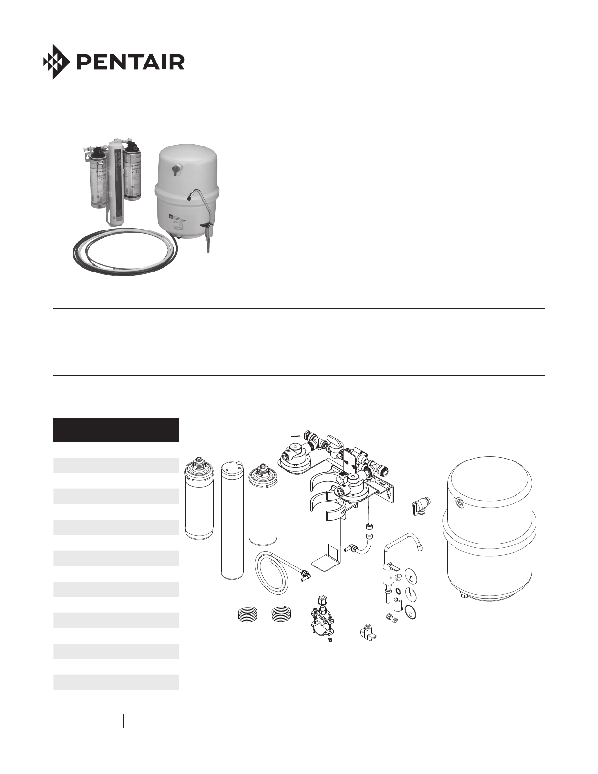
Before mounting the LVRO-75HE System, inspect the parts. Use the table and illustration provided to verify the parts
and quantities. If any parts are missing, contact Customer Service at 800.942.1153 (US only)/630.307.3000 or by email at
CSeverpure@pentair.com.
Parts
1. Head Assembly
2. RO Membrane GRO-75EN
3. 2FC5-S Filter Cartridge
4. 2CB5 Filter Cartridge
5. Tank Valve
6. Drain Saddle Valve
7. Water Supply Adapter
8. Storage Tank
9. Faucet Adapter
10. Change Indication Sticker
11. 3/8" Plastic Tubing (Blue)
12. 1/4" Plastic Tubing Assembly (Red)
13. Lead-Free Air Gap Drinking Water Faucet
14. Plug, 3/8" Quick-Connect
15. 3/8" Plastic Tubing (White)
16. Port Plug
3
2
11
14
4
12
15
1
8
5
6
16
13*
*Not in EV9975-00
7*
FOODSE RV IC E
LVRO-75HE REVERSE OSMOSIS SY STEM IN STALLATION AND OPERATION GU IDE
Page 2
Tools Required
• Hand or Electric Drill • Phillips Screwdriver
• Adjustable Wrenches (2) • Towel
• File • Safety Glasses
• Pencil • Tape Measure
• Utility Knife or Tube Cutter
(for plastic tubing)
• Drill Bits: 1/8-inch,
1/4-inch and 3/8-inch
Optional Materials
(For sinks without extra hole for faucet)
• Hand or Electric Drill • Center Punch
• Plumber Tape • Respirator
• Drill Bits: 1/4-inch and
3/4-inch
NOTE: Not all tools listed will be necessary for installation.
Read installation procedures before starting to
determine required tools.
• 1-3/8 inch Bi-metal or
Carbide Tipped Hole Saw
SELECTING A MOUNTING LOCATION
1. Give consideration to the weight of the unit when
operating, i.e. when filled with water. Operating weight of
the LVRO-75HE RO System is:
• System without Storage Tank - 10.2 lbs (4.6 kgs)
• Storage Tank - 29.4 lbs (13.3 kgs)
2. The location should allow for:
• Minimum clearance of 2-1⁄2 inches (6.3 cm) under the
cartridge(s) so they can be lowered for removal
and replacement.
• Adequate space for “in” and “out” water line
connections.
• Be near a drain for flushing.
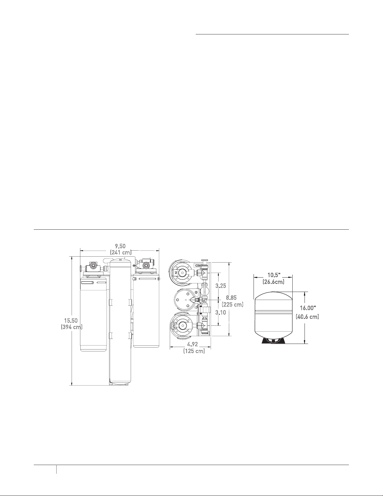
DIMENSIONS
15.50
(394 cm)
9.50
(241 cm)
4.92
(125 cm)
Figure 1
3.25
(225 cm)
3.10
8.85
10.5"
(26.6cm)
16.00"
(40.6 cm)
2 LVRO-75HE REVERSE OSMOSIS SY STEM IN STALLATION AND OPERATION GU IDE
Page 3

OPERATING SPECIFICATIONS
WARNING: Before installing the system, make certain
your water supply complies with the following
operating specifications. Failure to do so may
reduce the effectiveness of the system and will
void the warranty. Consult your local water
treatment utility or a certified water testing lab
to determine the quality for your water.
Temperature: 32-120°F (0-48°C)
Pressure: 40-125 psi (2.7-8.6 bar), non-shock
Total Dissolved Solids: 1000 ppm maximum
Maximum Hardness: 143 ppm
Sulfide, Iron and
Manganese:
Chlorine in Water Supply: Free chlorine - 0.1 ppm maximum
Water Supply pH Limits: 4 to 11
Turbidity: 1.0 NTU maximum
For cold water use only.
Less than 0.1 ppm
GENERAL PRECAUTIONS
WARNING: Do not use with water that is microbiologically
unsafe or of unknown quality without adequate
disinfection before or after the system. Systems
certified for cyst reduction may be used on
disinfected waters that may contain
filterable cysts.
WARNING: The LVRO-75HE RO System contains replaceable
components that are critical to the efficiency of
the system. Replacement of the reverse osmosis
component should be with one of identical
specifications, as defined by the manufacturer,
to assure the same efficiency and contaminant
reduction performance.
WARNING: The LVRO-75HE RO System contains a
replaceable RO membrane cartridge, critical for
the effective reduction of total dissolved solids.
Product water should be tested periodically to
verify that the system is working properly.
WARNING: The LVRO-75HE RO System shall only be used for
arsenic reduction on chlorinated water supplies
containing detectable residual free chlorine
at the system inlet. Water systems using an
in-line chlorinator should provide a one-minute
chlorine contact time before the unit.
WARNING: The LVRO-75HE RO System will not protect
against disease-causing bacteria or remove
naturally-occurring harmless bacteria.
CAUTION: The LVRO-75HE RO System must be protected
against freezing which can cause the filter
housing to crack, resulting in water leakage.
CAUTION: Turn off water supply to head without cartridge if
it must be left unattended for an extended period
of time.
CAUTION: Do not use electrical heating tape on this unit.
NOTE: Substances listed as reduced are not necessarily in
your water. System must be maintained according to
manufacturer's instructions, including replacement
of filter cartridges.
NOTE: Your water must be within required limits for
satisfactory operation. If not, the RO membrane
cartridge’s life may be shortened and your warranty
will be voided (see Operating Specifications).
NOTE: Install on cold water line only.
NOTE: Do not install where system will be exposed to direct
sunlight.
NOTE: Make certain that installation complies with all state
and local laws and regulations.
NOTE: The filter cartridges and RO membrane cartridge
included with the system have limited service lives.
Changes in taste, odor, and color of the filtered water
indicate that the cartridges and/or membrane should
be replaced.
NOTE: During extended periods of non-use (such as during
a vacation), remove the membrane cartridge and
the filter cartridges from the unit and place them
in a sealed plastic bag. Store the cartridges in the
refrigerator for future use. When restarting the unit,
replace all cartridges and flush per instructions.
NOTE: If the LVRO-75HE RO System stands for more than
two (2) to three (3) days without being used, the
storage tank should be emptied.
NOTE: Use only plumbers tape without adhesive backing
to seal joints. Do not use pipe compound (“pipe
dope”), sticks, or similar compounds with this unit;
they contain petroleum derivatives which can cause
crazing and cracking of the plastic in the filter
housing.
NOTE: Use only soap and water to clean components.
NOTE: Do not use aerosol sprays (bug spray, cleaning
fluids, etc.) near the LVRO-75HE RO System. They
contain organic solvents which can cause crazing and
cracking of the plastic in the filter housing.
NOTE: After prolonged periods of non-use, such as a
vacation, it is recommended that the system be
flushed thoroughly. Let water run for two (2) to three
(3) minutes before using.
NOTE: Do not use a torch near the unit.
3 LVRO-75HE REVERSE OSMOSIS SY STEM IN STALLATION AND OPERATION GU IDE
Page 4
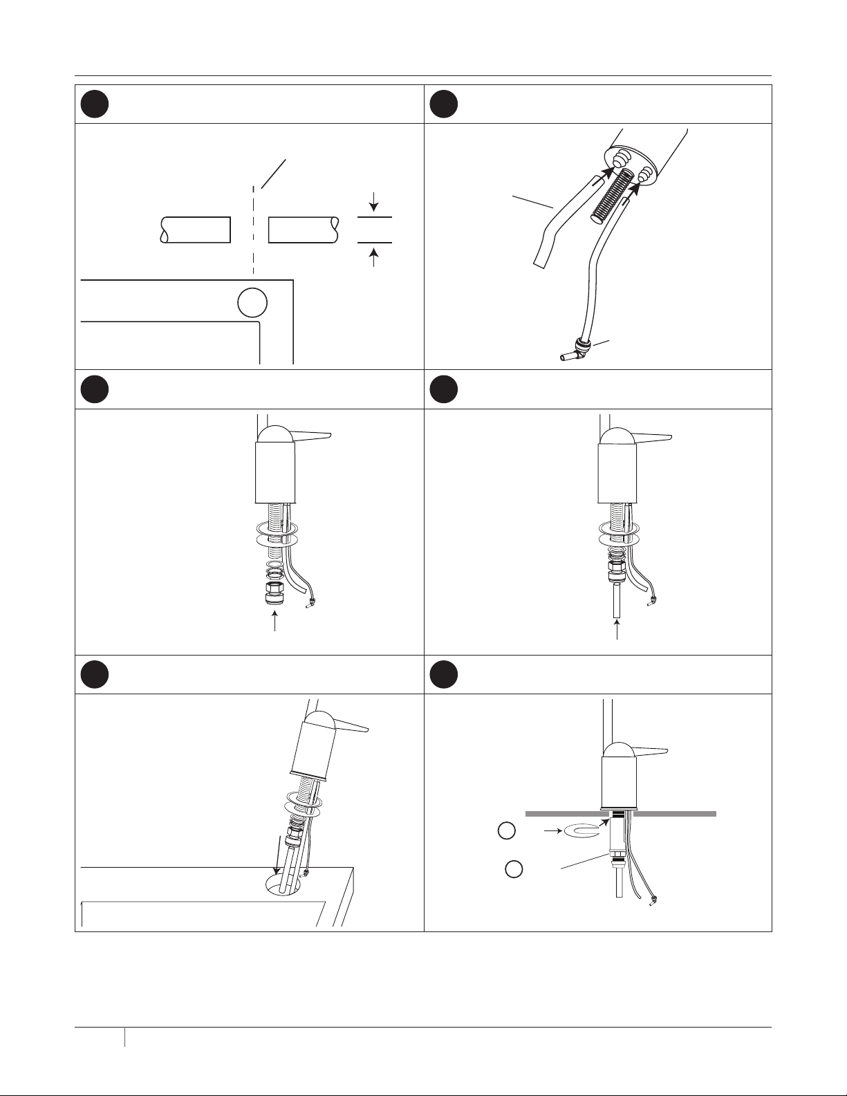
FAUCET QUICK START
2" Max
1
Mounting Hole Dimensions
1-3/8" to 1-1/2" Dia
sink goes
3
Attach Quick-Connector to Faucet
2
Attach Reject Water Tubing
3/8" Red
Tubing To
Drain
4
Attach Product Water Tubing
1/4" Red
Tubing
Elbow With
Flow Control
5
Position Faucet
3/8"
Blue
Tubing
6
Add "C" Washer and Tighten
Insert
1
Tighten
2
4 LVRO-75HE REVERSE OSMOSIS SY STEM IN STALLATION AND OPERATION GU IDE
Page 5
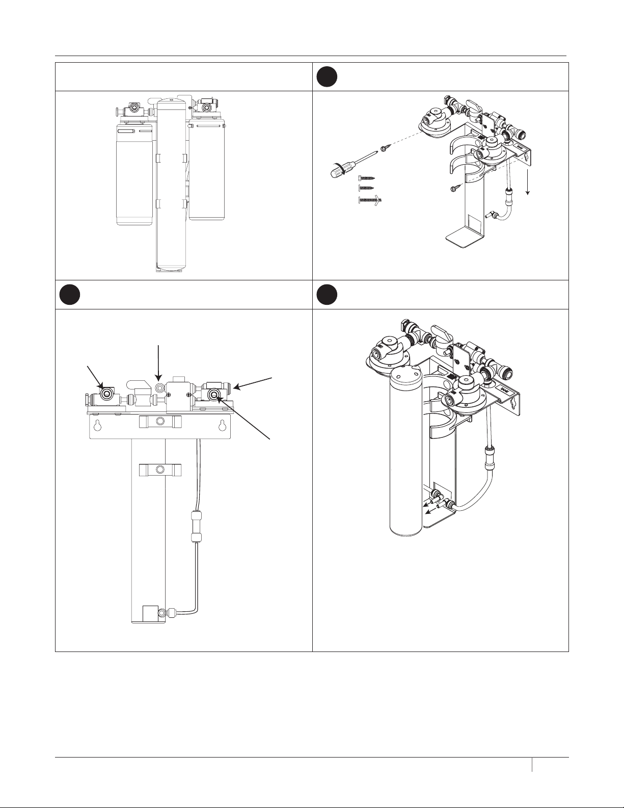
SYSTEM QUICK START
LVRO-75HE RO System
2
Tubing Locations
White 3/8" Tubing
Untreated Water
In - 3/8"
1-3/4" Length
Blue 3/8" Tubing
To Tank
1
Secure Manifold
3
Connect Tubing to GRO-75EN Cartridge
10.2 lbs
(4.62 kgs)
Blue 3/8" Tubing
To Faucet
5 LVRO-75HE REVERSE OSMOSIS SY STEM IN STALLATION AND OPERATION GU IDE
Page 6
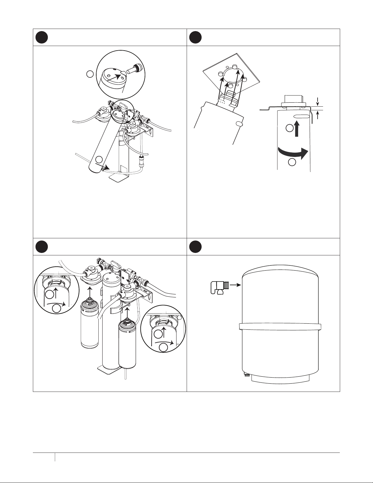
4
Install GRO-75EN Cartridge
1
5
Install Cartridges
3/16”
N
GRO-75E
2
6 7
1
1
90°
2
Assemble Tank
2
2FC5-S
2CB5
1
2
6 LVRO-75HE REVERSE OSMOSIS SY STEM IN STALLATION AND OPERATION GU IDE
Page 7
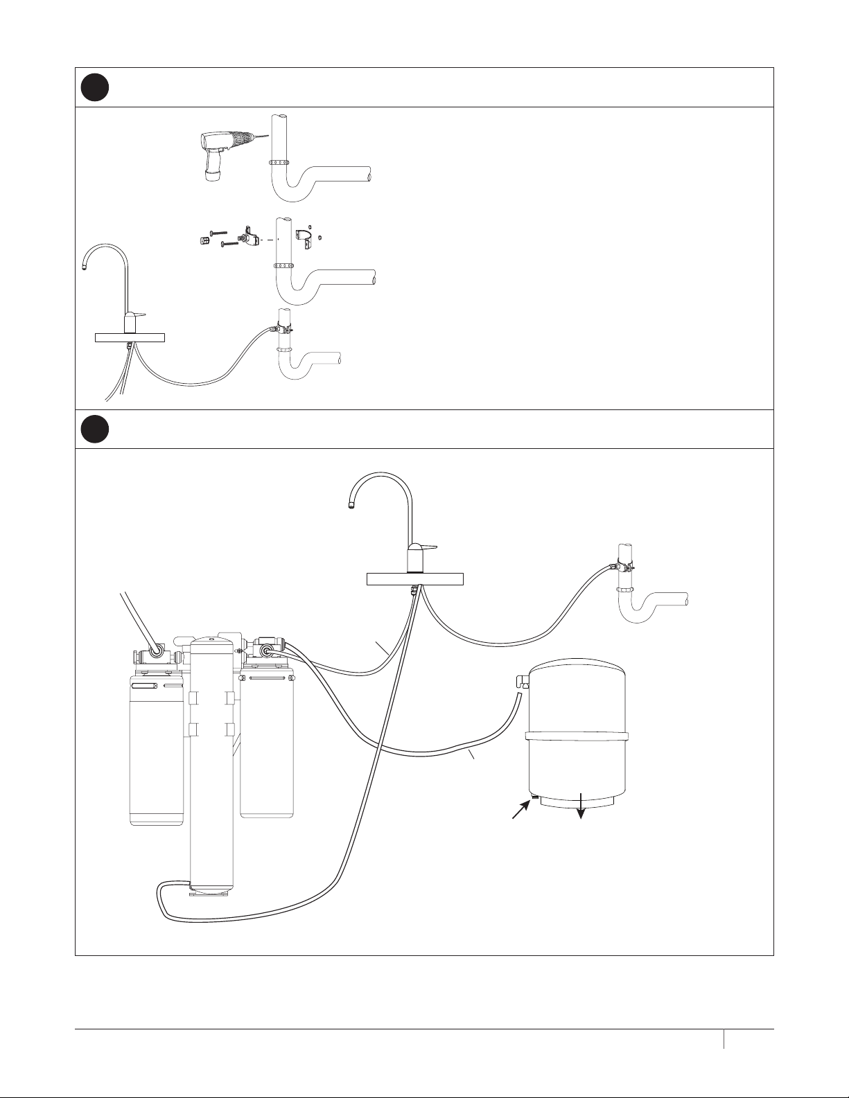
8
With Faucet - Connect To Drain
7
With Faucet - Connect Tank Tubing
White 3/8"
Tubing
Red 1/4
To Faucet
" Tubing
Blue 3/8"
Tubing
Red 3/8"
Tubing
Blue 3/8"
Tubing
5 to 7 PSI
(0.34 to 0.48 Bar)
35 lbs
(15.9 kgs)
7 LVRO-75HE REVERSE OSMOSIS SY STEM IN STALLATION AND OPERATION GU IDE
Page 8
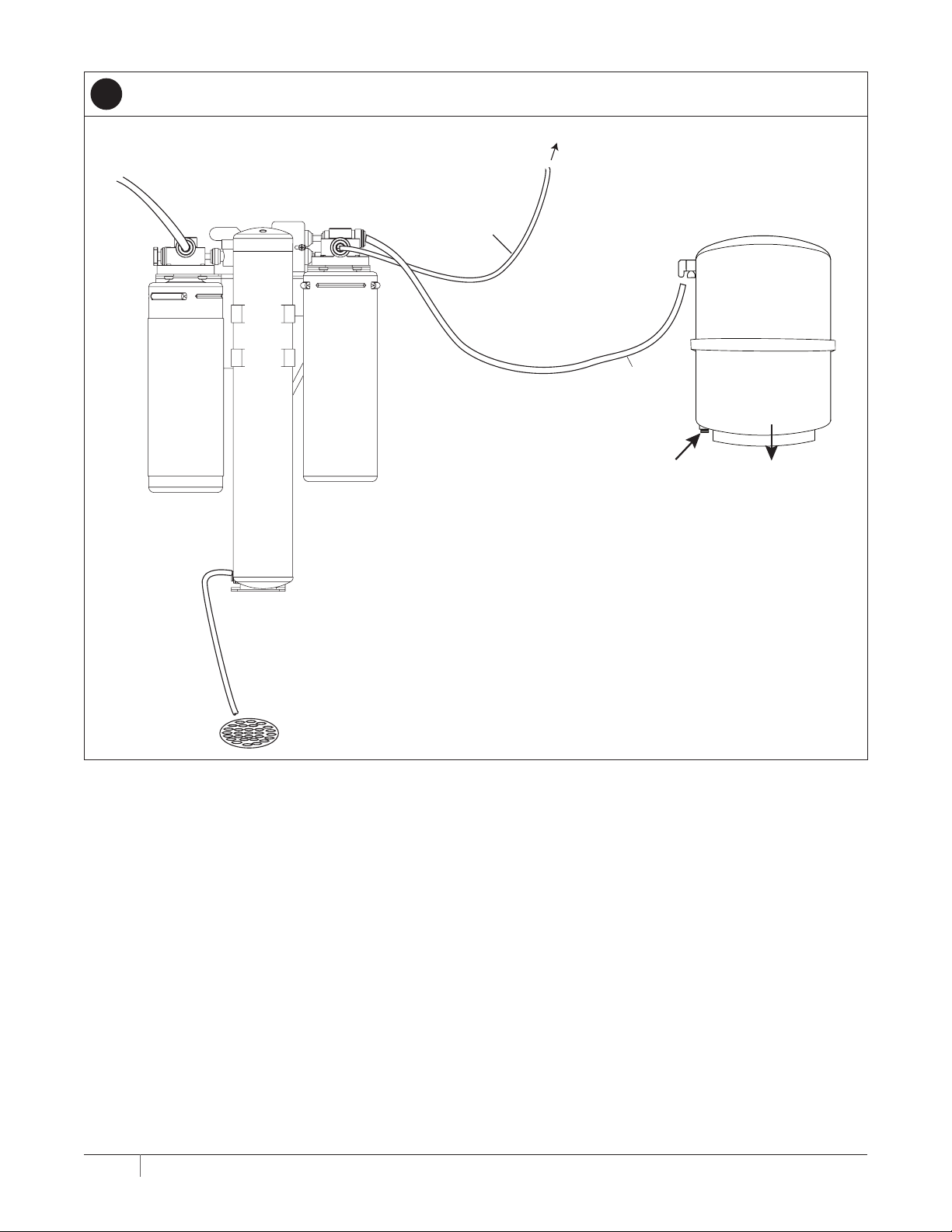
8
To Application
Without Faucet - Connect Drain and Tank Tubing
White 3/8"
Tubing
Blue 3/8"
Tubing
Blue 3/8"
Tubing
Red 1/4" Tubing
to Drain
5 to 7 PSI
(0.34 to 0.48 Bar)
35 lbs
(15.9 kgs)
8 LVRO-75HE REVERSE OSMOSIS SY STEM IN STALLATION AND OPERATION GU IDE
Page 9

PUT SYSTEM INTO OPERATION QUICK START
1
Flush 2FC5-S Cartridge
Close to connect tubing
Open for flush cycle
Closed
Remove
Plug
Insert
Tubing
OFF
To
Drain
Open
Flush for 5
minutes
2FC5-S
Closed
Red tubing
to faucet not
shown
9 LVRO-75HE REVERSE OSMOSIS SY STEM IN STALLATION AND OPERATION GU IDE
Page 10

2
Flush GRO-75EN and 2CB5 Cartridges
Close to remove tubing
Open for flush cycle
Insert
Plug
Remove
Tubing
Open
Flush for 12 hours
OPEN
To
Drain
GRO-75EN
2CB5
Red tubing
to faucet not
shown
Open
10 LVRO-75HE REVERSE OSMOSIS SY STEM IN STALLATION AND OPERATION GU IDE
Page 11

3
Final Flush
Open
Open
Close for 3 hours
Open for 5 minutes
Repeat 3 times
To
Drain
2FC5-S
GRO-75EN
2CB5
Red tubing
to faucet not
shown
Open
11 LVRO-75HE REVERSE OSMOSIS SY STEM IN STALLATION AND OPERATION GU IDE
Page 12

HOW REVERSE OSMOSIS (RO) WORKS
The LVRO-75HE RO System uses a semi-permeable
membrane to reduce dissolved salts, improving the taste and
odor of your water. The RO membrane cartridge contains
multiple layers of micron-thin film wound around a hollow
center core. Water molecules can pass through the cartridge,
while dissolved salts are rejected.
Your water supply is prefiltered to reduce dirt and chlorine
that may foul the membrane. The RO membrane cartridge
separates this prefiltered water into PRODUCT WATER and
REJECT WATER. Water pressure forces water through the
membrane within the RO membrane cartridge, and into
the storage tank. This is the product water. Dissolved salts
cannot pass through the membrane and are sent to the
drain as reject water. When the faucet is opened, product
water (permeate) is drawn from the storage tank through a
post-polishing filter. The post-polishing filter takes out any
remaining taste or odor in the water and provides you and
your family with cleaner, great-tasting water.
The LVRO-75HE RO System also features an auto shut-off
valve which shuts off the system once the pressure in the
storage tank reaches 2/3 of the incoming water pressure
(your water pressure). When you open the faucet to draw
water from the storage tank, the pressure inside the tank
drops and the auto shut-off valve opens. The system then
begins to operate, replenishing the water you took from the
storage tank. Depending on the system's efficiency, for each
gallon of water produced, up to 1 gal (3.79 L) is discharged as
reject water. The storage tank can hold up to 3.2 gals (12.1 L)
of water at a time.
NOTE: When used under operating conditions specified
in this manual, the RO membrane cartridge of the
LVRO-75HE RO System should last 12 to 24 months.
The precise life span of the RO membrane cartridge
will depend on the quality of the water entering
the system and the frequency with which you use
it. Frequent use prevents the dissolved salts from
building up on the membrane as scale. The more
water the system is required to produce, the longer
the membrane will last.
Selecting the Faucet Location
NOTE: The drinking water faucet should be positioned with
function, convenience, and appearance in mind. An
adequate flat area is required to allow faucet base to
rest securely. The faucet fits through a 1-3/8" hole.
Most sinks have pre-drilled 1-3/8" or 1-1⁄2" diameter
holes that may be used for faucet installation. If
these pre-drilled holes cannot be used or are in an
inconvenient location, it will be necessary to drill a
1-3/8" hole. This procedure may generate dust which
can cause severe irritation if inhaled or come in
contact with the eyes. The use of safety glasses and
respirator for this procedure is recommended.
WARNING: Do not attempt to drill through an
all-porcelain sink. If you have an all-porcelain
sink, mount the faucet in pre-drilled sprayer
hole or drill through countertop next to sink.
WARNING: When drilling through a countertop, make sure
the area below the drilled area is free of wiring
and piping. Make certain that you have ample
room to make the proper connections to the
bottom of the faucet.
WARNING: Do not drill through a countertop that is more
than 1-inch thick.
WARNING: Do not attempt to drill through a tiled, marble,
granite or similar countertop. Consult a plumber
or the countertop manufacturer for advice or
assistance.
1. Line bottom of sink with newspaper to help prevent
metal shavings, parts, or tools from falling down drain.
2. Place masking tape over the area to be drilled to help
prevent scratches if drill bit slips.
3. Mark hole with center punch. Use a 1/4" drill bit for a
pilot hole.
4. Using a 1-3/8" hole saw, drill a hole completely through
the sink. Smooth the rough edges with a file.
INSTALLATION
NOTE: Please read all instructions, specifications, and
precautions before installing and using your
LVRO-75HE RO System.
NOTE: The LVRO-75HE RO System may be installed under a
sink, counter or water cooler.
NOTE: The LVRO-75HE RO System is installed vertically.
NOTE: Numbered diagrams correspond with
numbered steps.
12 LVRO-75HE REVERSE OSMOSIS SY STEM IN STALLATION AND OPERATION GU IDE
D
11⁄4”
4
3
1
4”
⁄
Figure 2
2
1
Page 13

Mounting the Faucet
1. Loosen stem-nut on faucet, remove metal "C" disc
(if attached).
2. Attach large diameter 3/8" (red) drain tube to barb fitting
at the faucet base. This tube should be long enough to
reach the drain clamp.
3. Locate the 1/4" red brine tube that has a preassembled
quick-connect elbow on one end. Connect the open end
to the small barb on the faucet. Make certain that the
tube is not kinked or stressed once the head assembly is
mounted.
4. Slide chrome plate and black rubber washer onto faucet
by threading both drain tubes through the holes in the
plate and washer.
5. Slide white extension onto long threaded section of
faucet. Open end of extension should come in contact
with base of faucet.
6. Slide the washer then the lock washer up threaded
section and thread stem nut on. Do NOT tighten nut at
this time.
7. Apply three (3) to five (5) wraps of plumbers tape to
faucet stem. Screw quick-connector onto end of threads.
8. Wet end of blue 3/8" tube. Push into bottom of connector.
for 3/4". Tug gently to be sure connection is complete.
9. To remove the tube, push on the fittings' collar and pull
the tube out.
10. Holding the faucet, feed the three (3) tubes through the
hole in the sink. Position the faucet handle at a
desired location.
11. Center the faucet and slip "C" disc between the white
extension and the bottom of the counter or sink. Tighten
the stem nut with a wrench until it is tight.
NOTE: Do not overtighten the lock nut. Snug down and
tighten until faucet is secure.
12. Firmly insert goose-neck spout into faucet base.
2
3
4
Countertop
10
5
1
6
7
8
Figure 3
Mounting the System
CAUTION: The filter head assembly should be mounted on a
stud or firm surface. The mounting bracket will
support the weight of the cartridges and help
prevent strain on the water lines.
1. Select location where unit is to be mounted. The head
assembly is mounted in a vertical position.
2. When mounting the LVRO-75HE RO System, two (2)
screws are required to mount the head. Measure up from
the floor of the cabinet 15.5" (39.4 cm). See Figure 4.
This will provide clearance to change the cartridges. The
two (2) screws will be 14" (35.6) apart and level. Screw
the two (2) screws into the wall. Leave a gap between
the screw head and the wall of 1/8". The backside of the
system head has two (2) slots that will fit over the screw
heads and slide down to lock.
2" clearance below cartridges
Figure 4
12.5" from mounting hole
to bottom of cartridge
13 LVRO-75HE REVERSE OSMOSIS SY STEM IN STALLATION AND OPERATION GU IDE
Page 14

Connecting the Faucet
CAUTION: Water supply to the inlet of the LVRO-75HE RO
System should have a separate shut-off valve. If it
does not, a separate shut-off should be installed.
1. Locate the 3/8" blue tubing from the faucet. See Figure
5. The tubing must not have sharp bends or kinks that
would restrict water flow. Cut length as needed. Place a
mark 3/4" (1.9 cm) from the end of the tubing.
IMPORTANT: A length of this 3/8" blue tubing will be
used to connect the storage tank to the manifold. When
cutting this tube, plan for the new piece to be used for
the tank.
Moisten the end of the tubing with water and insert
into the water outlet quick-connect fitting on the head
assembly . Push in until the mark is flush with the
quick-connect fitting.
2. Gently pull back on the tubing to ensure it is connected
properly. If the tubing comes out of fitting, cut a small
section off of the tubing and reconnect.
NOTE: Tubing may be quickly and easily removed from the
fitting if necessary. First, turn off the water supply to
the filter. Open faucet, then press in the collet around
the fitting while pulling the tubing with your other hand.
Carbon Filtered
Only Water Out Remove Plug
Untreated
Water In
2FC5-S
GRO-75EN
2CB5
Blue 3/8"
Red 1/4"
Figure 5
Red 3/8"
Blue 3/8"
14 LVRO-75HE REVERSE OSMOSIS SY STEM IN STALLATION AND OPERATION GU IDE
Page 15

15 LVRO-75HE REVERSE OSMOSIS SY STEM IN STALLATION AND OPERATION GU IDE
Connecting the Water Supply
1. Determine the length of 3/8" white plastic tubing needed
to connect the inlet on the left side of the filter with the
water supply. Be sure to allow enough tubing to prevent
kinking and cut the tubing squarely. Place a mark 3/4"
(1.9 cm) from the end of the tubing.
2. Wet tubing with water and insert tubing into water supply
fitting 3/4" (1.9 cm) until mark is flush with fitting.
Installing the Drain Clamp
NOTE: If you have a single-basin sink with a disposal
unit, call Technical support at 800.942.1153 (US
only)/630.307.3000 for options.
NOTE: Before installing the drain clamp, check the drain
pipes under the sink for corrosion. Corroded pipes
should be replaced before continuing
with installation.
3. Attach the drain clamp to a vertical section of the drain
pipe, about 6" (15.2 cm) above the trap. Make sure
the opening on the drain clamp is facing towards the
drinking water faucet. See Figure 6.
6 inches
Figure 6
4. Using the fitting hole of the drain clamp as a guide, drill
a 1/4" (0.6 cm) hole through one side of the drain pipe.
See Figure 7.
5. Remove the drain clamp from the drain pipe and enlarge
the hole with a 3/8" (1.0 cm) drill bit. Use a file to remove
rough edges from the drilled hole.
Figure 7
6. Make sure the black rubber gasket is adhered to the
inside of the drain clamp and place the drain clamp
assembly over the drilled hole. Look through the hole
and position the clamp so that the center of the clamp
hole is slightly higher (about 1/16") than the center of the
drilled hole, see Figure 8. Tighten the clamp securely.
7. Screw the plastic compression nut onto the drain clamp
until finger-tight.
Figure 8
Connecting the Faucet to the Drain
NOTE: This is a gravity-fed drain line. Any loops, kinks or
sharp bends must be eliminated before proceeding.
Failure to create a straight line to the drain may
result in reject water leaking through the air gap in
the faucet onto the countertop and below the faucet.
1. Align the 3/8" red tubing from the faucet with the
compression nut on the drain clamp, see Figure 9.
Create as straight a path as possible with the tubing.
Cut the tubing squarely below the nut and remove the
internal and external burrs.
2. Loosen the compression nut two (2) complete turns.
Insert the tubing into the nut until it stops. Tighten with
fingers, then tighten one (1) to two (2) turns with
a wrench.
Figure 9
Page 16

INSTALLING THE CARTRIDGES
The cartridges are identified by the color of the label and the
model number.
Cartridge #1: Everpure 2FC5-S Filter Cartridge
Cartridge #2: Pentair GRO-75EN RO Cartridge
Cartridge #3: Everpure 2CB5 Filter Cartridge
Install the cartridges in order. If the cartridges are installed
out of order, the system will not filter correctly.
Install the GRO-75EN Cartridge
The GRO-75EN Reverse Osmosis (RO) Cartridge is installed in
the vertical position. There are three (3) quick-connect ports
that are labeled.
• Inlet -White
• Permeate (product water ) - Blue
• Drain - Red
This cartridge is installed before the two outside cartridges.
The manifold assembly should already be mounted securely.
7
9
450
11
12
Swing
Down
1
4
2
3
6
5
Figure 10
The numbers in Figure 10 refer to the Steps below.
1. Locate the red drain tubing with the preassembled elbow
fitting. This tube has already been assembled to
the faucet.
CAUTION: DO NOT remove the quick-connect elbow fitting
from the red tubing. This assembly contains
a flow control that may become damaged if
removed. The efficiency of the LVRO-75HE RO
System may be affected.
2. Mark the short piece of red drain tubing 5/8" (1.6 cm)
from the end.
3. Insert the tube into the red drain port at the bottom of
the cartridge, Figure 11. Push it in until the mark is flush
with the quick-connect fitting.
4. The product water tube (blue) is preassembled to the
manifold. Inspect the check valve to be certain the flow is
in the upward direction.
5. Mark the short piece of tubing 5/8" (1.6 cm) from
the end.
6. Insert the tube into the blue permeate port at the bottom
of the GRO-75EN Cartridge, Figure 11. Push it in until the
mark is flush with the quick-connect fitting.
7. Locate the tubing that will become installed into the
inlet port of the GRO-75EN Cartridge. The tubing should
be installed in the elbow fitting coming out of the auto
shut-off valve. The length of the tube that is visible must
be 1" (2.5 cm).
8. Measure 5/8" (1.6 cm ) from the end of the tube and
mark it.
9. Rotate the quick-connect elbow upward 450.
10. Position the GRO-75EN Cartridge so the inlet port is in
position in front of the tubing. The cartridge will be tipped
out at the bottom and will not yet be held by the clips.
11. Push the cartridge onto the tubing until the 5/8" (1.6 cm)
mark is flush with the quick-connect fitting.
12. Swing the cartridge down. The elbow fitting must move
with the cartridge. The cartridge will snap into the two
clips. The tubing and the elbow should point directly into
the inlet port.
13. If the tubing does not position directly into the inlet port,
the cartridge should be slid up or down as needed.
NOTE: The bottom of the GRO-75EN Cartridge will be
supported by the lower leg of the bracket.
Blue Permeate
GRO-75EN
Cartridge
Red Drain
Figure 11
16 LVRO-75HE REVERSE OSMOSIS SY STEM IN STALLATION AND OPERATION GU IDE
Page 17

Install the 2FC5-S Cartridge
Locate the 2FC5-S Cartridge and inspect the o-rings. They
should be clean and lightly lubricated with silicone grease.
1. Line up the tabs with the slots in the opening on the left
side of the head assembly. See Figure 12.
2. Insert the cartridge to full depth.
3. Rotate the cartrdige 900 to the right (clockwise) to lock it
in place.
Figure 12
PUTTING THE SYSTEM INTO OPERATION
CAUTION: Make certain head assembly is firmly attached
to wall to prevent it from falling and possibly
becoming damaged.
NOTE: The MRS-75EN RO System does not produce a high
volume of water on-demand as an ordinary filter
does. Water is produced at a slow, drop-by-drop rate.
The system requires about three (3) hours to fill the
storage tank. As water is taken from the tank, the
system automatically starts the cycle of replacing the
water and then stops water production when the tank
is full.
There are several steps that must be followed to properly
place the LVRO-75HE RO System into operation. Before the
supply water is turned ON, see Figure 13:
• Remove quick-connect plug on the left end of the
manifold and connect the port with tubing to a drain.
• Turn shut-off valve to the OFF position.
• Turn tank valve to the OFF position.
• The faucet lever should be closed.
Quick-Connect Plug
Incoming Water
Shut-Off Valve
Install the 2CB5 Cartridge
Locate the 2CB5 Cartridge and inspect the o-rings. They
should be clean and lightly lubricated with silicone grease.
1. Line up the tabs with the slots in the opening on the right
side of the head assembly. See Figure 12.
2. Insert the cartridge to full depth.
3. Rotate the cartridge 900 to the right (clockwise) to lock it
in place.
Connecting the Storage Tank to the System
CAUTION: When tank is full, it weighs approximately 30 lbs
(13.6 kgs). Provide ample support under the tank.
1. Thread the tank valve onto the tank opening by turning it
clockwise until snug.
2. Locate the piece of blue tubing (cut off earlier) and mark
it 3/4" (1.9 cm) from the end. Moisten one end of the blue
tubing with water and insert with a twisting motion into the
port of the tank valve until the 3/4" mark is flush with the
quick-connect fitting.
3. Mark the remaining end 3/4" (1.9 cm) from the end. Wet the
end and insert into the open connection on the last (right
side) head until the 3/4" mark is flush with the quickconnect fitting.
NOTE: The pressurized storage tank has capacity of 3.2 gals
(12.1 L). The tank's air pressure is factory-set at 5 to
7 psi when tank is empty.
Tank Valve
Figure 13
1. To flush the 2FC5-S Cartridge to a drain, remove the
quick-connect plug on the left end of the manifold and
insert a temporary length of tubing into the connection.
NOTE: Tubing and ball valve are supplied.
Turn on the incoming water supply. Flush the 2FC5-S
Cartridge to a drain for five (5) minutes at full flow to
remove any carbon fines.
CAUTION: Failure to flush the 2FC5-S Cartridge will damage
the GRO-75EN RO Membrane Cartridge. This
condition will void the warranty.
2. After five (5) minutes, close the incoming water valve.
Remove the temporary tubing and re-insert the quickconnect plug.
17 LVRO-75HE REVERSE OSMOSIS SY STEM IN STALLATION AND OPERATION GU IDE
Page 18

3. Make sure tank valve is in the open position.
4. Open the shut-off valve.
5. Slowly turn on incoming water supply.
6. Open the faucet to turn on flow. Let the faucet run/drip
for 12 hours, then close it.
7. Allow three (3) hours for the tank to fill. Continue to
periodically check the installation for leaks. After
the storage tank is filled, open the faucet to flush the
postfilter cartridge (on the right side of the filter housing
assembly). Allow four (4) to five (5) minutes for all of the
water to drain from the tank. Close faucet and allow tank
to fill.
8. Repeat Step 7 three (3) times.
CAUTION: Visually check the entire system for leaks. If a
leak is present, see Troubleshooting.
NOTE: Initially, the water may appear cloudy. This is a result
of air trapped in the postfilter cartridge. It is not
harmful and will disappear in a matter of minutes. It
may take up to a week after installing a new
postfilter cartridge for the trapped air to dissipate.
The system is ready for operation. You can now enjoy quality
water from the LVRO-75HE RO System.
TESTING YOUR REVERSE OSMOSIS SYSTEM
Total Dissolved Solids (TDS) Test
NOTE: Under NSF/ANSI Standard 58, it is highly
recommended that the product water is tested at
least every six (6) months to verify that the system is
performing satisfactorily.
WHEN TO CHANGE THE CARTRIDGES
The life of the cartridge depends on the water volume used
and the substances in the water. Normally, cartridges should
be changed at intervals of 12 months. Replace the cartridge
sooner if the water pressure at the faucet begins to drop
noticeably or if you notice changes in the taste, color, or flow
of the filtered water.
CHANGING THE CARTRIDGES
Replacement Cartridges:
Everpure 2FC5-S Filter Cartridge - EV9691-86
Everpure 2CB5 Filter Cartridge - EV9617-05
Pentair GRO-75EN RO Cartridge - 4002575
The prefilter and postfilter cartridges need to be changed
when the water pressure at the faucet begins to drop
noticeably or if there are changes in taste, color or flow of
the filtered water. All cartridges should be changed at the
same time. The cartridges are color-coded to indicate which
location they are installed into.
NOTE: Only the replacement cartridges listed can be used
with this system. Failure to use the recommended
replacement cartridges will void your warranty.
1. Place a small pan or towel under the LVRO-75HE RO
System to catch any water tha may drip. Turn OFF
incoming water.
2. Remove the two (2) outside cartridges by twisting each
cartridge a 1/4-turn to the left (counterclockwise). Then
pull down to release.
3. Remove the center GRO-75EN Cartridge by swinging the
cartridge up and out, pivoting at the top connection. Once
the cartridge is out of the clips, the quick-connection at
the top can be disconnected. Disconnect both tubes from
the quick-connect fittings at the bottom.
4. Connect the red and blue tubes at the bottom of the new
GRO-75EN Cartridge.
5. Position the new GRO-75EN Cartridge so the inlet port
is in position in front of the tubing at the top of the
cartridge. Push the cartridge onto the tubing until it
reaches full depth. Swing the cartridge down (the elbow
fitting must swing with it) into the clips. Adjust the
cartridge up or down so the tubing and the elbow point
directly into the cartridge.
NOTE: The bottom of the GRO-75EN Cartridge will be
supported by the lower leg of the bracket.
6. Position the 2FC5-S Cartridge under the left side head.
Line up the tabs on the cartridge with the slots in the
head.
7. Push the new cartridge into the head until it can go no
further.
8. Twist the cartridge a 1/4-turn to the right (clockwise)
until it locks in place. Pull gently down to ensure the
cartridge is locked in place.
9. Repeat Steps 6, 7 and 8 for the 2CB5 Cartridge.
CAUTION: The 2FC5-S Cartridge may contain carbon fines
that will be removed during the initial flushing.
Follow the proper flushing procedure to prevent
damage to the GRO-75EN RO Cartridge.
18 LVRO-75HE REVERSE OSMOSIS SY STEM IN STALLATION AND OPERATION GU IDE
Page 19

INITIAL FLUSHING OF CARTRIDGES
The installation of new cartridges requires that a preliminary
flushing of the cartridges be performed. This initial flushing
is requried to prevent damage to the RO cartridge.
Refer to the Installation section and Step 11, Putting the
System into operation for the complete flushing procedure.
SANITIZING PROCEDURE - CONTAMINATED WATER
SUPPLY/BOIL ALERTS
When the water system has been contaminated or a boil
water advisory has been discontinued, the LVRO-75HE RO
System must be sanitized. If a boil water advisory has just
been discontinued: Flush the water lines according to your
water supplier's instructions. Open the delivery faucet and
flush the system for about 10 minutes, then follow the filter
cartridge replacement instructions below.
1. Turn off the water supply and open the faucet to
relieve pressure.
2. Remove the filter cartridges and discard in trash. Wash
hands with soap and warm water.
NOTE: If a drip pan is used, clean with dish soap and
warm water.
NOTE: The following steps require placing bleach into the
LVRO-75HE RO System. Pentair Everpure offers a
hollow cartridge, Everpure 2JT Flushing/Sanitizing
Cartridge (EV9608-10), that is designed for this
application. The following steps describe how to use
the Pentair Everpure 2JT Cartridge (EV9608-10).
Sanitization Procedure With The Pentair
Everpure® 2JT Cartridge (EV9608-10)
3. Grasp the tip of the outlet tower center, top of the
cartridge and pull out gently. The entire central plug with
the long tube attached will come out, leaving a hole.
Figure 14
4. Add about a teaspoon of laundry bleach (5.25% sodium
hypochlorite solution) to the empty flushing cartridge
through the hole in the top.
5. Lubricate o-ring with a high quality silicone lubricant.
Replace the central plug assembly and insert the
flushing cartridge into the first (left side) installed head.
NOTE: Do not use petroleum jelly to lubricate the o-rings. It
will degrade the o-rings.
CAUTION: DO NOT install the GRO-75EN RO Membrane
Cartridge for the sanitization procedure. The
solution will severely damage the membrane.
Figure 15
6. Install a port plug into the last (right side) head.
7. When the RO cartridge is removed, the blue tube from
the bottom of the cartridge can be used for the sanitizing
procedure. Remove the quick-connect elbow on the blue
tube and remove the short tube at the top
quick-connect elbow.
8. Connect the bottom end of the blue tubing to the quickconnect elbow that is normally connected to the inlet
port of the RO cartridge.
9. The tank valve and the manifold shut-off valve should be
open. The faucet should be OFF.
10. Slowly open the water supply valve. Open the faucet and
monitor the water flowing out of the LVRO-75HE RO
System. When the smell of chlorine is present, close the
faucet valve. The storage tank will fill with
chlorinated water.
11. Wait for a period of at least 30 minutes to allow adequate
disinfection time.
12. Turn off the incoming water valve.
13. Open the faucet valve. The storage tank will drain out.
14. When the storage tank is emptied, close the faucet valve
and remove the 2JT Cartridge.
15. Install a new 2FC5-S Cartridge in the first (left
side) head.
16. Open the faucet valve and slowly open the incoming
water valve. Allow water to run for five (5) minutes. This
will flush carbon fines out of the new cartridge.
17. Close the faucet allowing the tank to fill three (3) to five
(5) minutes.
18. Turn off the incoming water valve.
19. Open the faucet to allow the tank to empty.
20. When the water flow has stopped, close the faucet and
open the incoming water valve to refill the tank for three
(3) to five (5) minutes.
21. Repeat Steps 17, 18 and 19 four (4) times.
22. Turn off the incoming water valve and open the faucet to
remove pressure.
19 LVRO-75HE REVERSE OSMOSIS SY STEM IN STALLATION AND OPERATION GU IDE
Page 20

23. Install the new 2CB5 Cartridge in the last (right
side) head.
24. Open the faucet and the incoming water valve. Allow
water to run for five (5) minutes to flush the 2CB5
Cartridge. Then close the incoming water valve.
25. Install a new GRO-75EN RO Cartridge.
26. Open the incoming water valve. Allow the faucet to drip
for 12 hours to flush the RO cartridge.
27. Close the faucet. The storage tank will fill.
The LVRO-75HE RO System is ready for operation.
TROUBLESHOOTING
NOTE: If leaks persist, or if there are other leaks on system,
turn off water supply and call Technical Support
800.942.1153 (US only)/630.307.3000.
Leaks Between Cartridge and Filter Housing
1. Turn off cold water supply to system. Close tank valve.
Open drinking water faucet to relieve water pressure.
2. Remove the cartridge, inspecting it for damage. Inspect
o-rings to make sure they are seated and clean.
3. Insert and twist the cartridge back into the filter housing.
4. Turn on water supply. Open tank valve. Close drinking
water faucet after water begins to flow. If leaks persist,
call Technical Support.
Leak Between Tank Valve and Storage Tank
1. Turn off water supply to system. Open faucet to drain
storage tank. Let faucet run for three (3) to five (5)
minutes until it drips.
2. Remove blue tubing from tank valve by pressing the collar
around the fitting while pulling the tubing with your
other hand.
3. Unscrew the tank valve from the storage tank.
4. Inspect the rubber seal inside the threaded area. Repair
or replace the valve as needed.
5. Thread the tank valve onto the top of the tank opening by
turning it clockwise until snug.
6. Cut off 1" (2.5 cm) of tubing. Tubing should be cut
squarely. Internal and external burrs should be removed.
Place a mark on tubing 3/4" (1.9 cm) from end of tubing.
7. Wet the tubing and insert until the mark is flush with the
quick-connect fitting.
8. Turn water supply on and close drinking water faucet.
9. Allow system to pressurize for several hours and check
for leaks.
10. Check for leaks after tank is fully pressurized [one (1) to
three (3) hours]. If leak persists, call Technical Support .
Leaks at Quick-Connect Fittings
CAUTION: The 1/4" red tubing connected to the bottom
drain connection of the RO cartridge has a flow
restrictor installed. The system will not operate
correctly if the restrictor is removed.
1. Close tank valve, turn off cold water supply to the
system, and open drinking water faucet.
2. Press collar around the quick-connect fitting while
pulling the tubing with your other hand.
3. Cut off 1" (2.5 cm) of tubing. Tubing should be cut
squarely. Internal and external burrs should be removed.
Place a mark on tubing 5/8" (1.6 cm) from end on 1/4inch tubing or 3/4" (1.0 cm) from end on 3/8" tubing.
4. Wet the end and insert tubing until the mark is flush with
the quick-connect fitting.
5. Open the cold water supply until it comes to a stop. Open
the tank valve and close drinking water faucet. If leaks
persist, call Technical Support.
Leaks from Faucet
1. Check to make sure red tubing leading from the drinking
water faucet to the drain is as straight as possible (it is
usually necessary to cut this line during installation). Any
kinks or sags in this drain line will impede the flow of
water to the drain.
2. Check to make sure the drain clamp and the drain hole
are properly aligned, refer to Figure 8).
3. Check to make sure there is no foreign matter clogging
the drain line or at the drain clamp hole. If leaks persist,
call Technical Support.
No Flow or Slow Flow from the Brine (Reject) Line (Less
than 6 fl. oz. or 180 mm per minute)
NOTE: Before checking brine (or reject) flow, make sure
the unit is producing water by turning the valve on
the storage tank off and opening the drinking water
faucet. Water should drip from faucet.
1. Replace the prefilter cartridge according to the Changing
the Cartridge Instructions on page 10 and recheck the
brine (or reject) flow rate.
2. If the prefilter cartridge is not at fault, the brine (or
reject) flow controller could be clogged. Call
Technical Support.
High TDS in Product Water
1. If high TDS (Total Dissolved Solids) is detected in the
product water, the RO cartridge may need to be replaced
or the reject flow control tubing may be clogged. If this is
a new installation, call Technical Support.
2. Otherwise, draw 1 gal (3.8 L) of water from the unit. After
10 minutes, run water from the faucet and test the water
again.
3. Determine when you last changed the RO cartridge and
call Technical Support.
20 LVRO-75HE REVERSE OSMOSIS SY STEM IN STALLATION AND OPERATION GU IDE
Page 21

Limited Flow at Drinking Water Faucet
1. Turn off water supply to system.
2. Open the faucet to turn on flow.
3. Unscrew the black cap at the base of the storage tank to
expose air valve. Use a small air compressor or bicycle
pump to add air to the storage tank. This will force
the water out of the storage tank through the faucet.
Continue to add air until no more water comes out of the
faucet.
4. Turn off the drinking water faucet.
5. Using an air pressure gauge, adjust the pressure in the
storage tank to 5 to 7 psi (0.34 to 0.48 bar).
6. Replace the black cap.
7. Open the incoming water valve until it comes to a stop.
Let the system run one (1) to three (3) hours to fill the
tank. A full tank weighs approximately 29.4 lbs (10.2 kgs)
pounds. If performance has not improved, call
Technical Support.
The tested recovery rating is 40.17%. Recovery rating means
the percentage of the influent water to the membrane portion
of the system that is available to the user as reverse osmosis
treated water when the system is operated without a storage
tank or when the storage tank is bypassed.
Daily Production Rate: 14.66 gpd
This system has been tested for the treatment of water
containing pentavalent arsenic (also known as As(V), As(+5),
or arsenate) at concentrations of [0.050 mg/L or 0.30 mg/L]10
or less. This system reduces pentavalent arsenic, but may
not remove other forms of arsenic. This system is to be
used on water supplies containing a detectable free chlorine
residual or on water supplies that have been demonstrated to
contain only pentavalent arsenic. Treatment with chloramine
(combined chlorine) is not sufficient to ensure complete
conversion of trivalent arsenic to pentavalent arsenic. Please
see the Arsenic Facts section of the Performance Data Sheet
for further information.
Sudden Return of Taste and Odor
If shortly after complete servicing, noticeable taste and odors
return, contact Technical Support.
If you are experiencing a problem not listed in this manual,
shut off the water supply and close the tank valve. Call
Technical Support.
NOTES
Check for compliance with state and local laws and
regulations.
Do not use with water that is microbiologically unsafe or of
unknown quality without adequate disinfection before or after
the system.
For installations in Massachusetts, the Commonwealth of
Massachusetts Plumbing Code 248 CMR shall be adhered
to. Consult your licensed plumber for installation of the
system. This system and its installation must comply with
state and local regulations.
Systems certified for cyst reduction may be used on
disinfected waters that may contain filterable cysts.
Substances that may be reduced are not necessarily in your
water. Filter must be maintained according to manufacturer’s
instructions, including replacement of filter cartridges.
The tested efficiency rating for this system is 18.11%.
Efficiency rating means the percentage of the influent water
to the system that is available to the user as reverse osmosis
treated water under operating conditions that approximate
typical daily usage.
REPLACEMENT PARTS
Contact your local Pentair® Everpure® Dealer for filter
cartridges or system replacement parts.
Description Part Number
TDS Test Kit
RO Membrane GRO-75EN
2FC5-S Filter Cartridge
2CB5 Filter Cartridge
Tank Valve
Drain Saddle Valve
Water Supply Adapter - Faucet
Storage Tank
3/8" Plastic Tubing (Blue)
1/4" Plastic Tubing Assembly (Red)
Lead-Free Air Gap Drinking Water Faucet
Plug, 3/8" Quick-Connect
Port Plug
EV6500-57
4002575
EV9691-86
EV9617-05
EV3116-55
EV3117-54
EV3129-38
EV3144-71
EV3144-73
EV3050-61
244959
EV3144-87
EV3108-76
The LVRO-75HE RO System is Tested and
Certified by NSF International against NSF/
ANSI Standard 58 for the reduction of the claims
specified on the Performance Data Sheet or at
www.nsf.org
21 LVRO-75HE REVERSE OSMOSIS SY STEM IN STALLATION AND OPERATION GU IDE
Page 22

22 LVRO-75HE REVERSE OSMOSIS SY STEM IN STALLATION AND OPERATION GU IDE
Page 23

LIMITED WARRANTY
COMMERCIAL WATER TREATMENT EQUIPMENT
You have just purchased one of the finest water treatment units made. As an expression of confidence in this product, Pentair Filtration
Solutions, LLC (“PFS”) offers the following product warranty. This product is warranted against material defects in materials and
workmanship to the original end-user when installed in accordance with the PFS specifications. The warranty period commences on the
date of purchase and is administered as follows:
For a period of ONE YEAR Replaceable elements (i.e., filter & water treatment cartridges)*
For a period of FIVE YEARS The entire system (excluding replaceable elements)
The unit must be used in operating conditions that conform to PFS’s recommended guidelines. This warranty will not apply if the unit
has been modified, repaired or altered by someone not authorized by PFS.
If a part described above is found to have a material defect in materials or workmanship within the specified warranty period, you
should notify Pentair
of this warranty will be repaired or replaced (at PFS’s discretion) by your local dealer or Pentair Everpure technical service. You pay only
freight from our factory and local dealer charges. Any item repaired or replaced pursuant to this warranty will be covered under the
original warranty terms of the system.
PFS is not responsible for damage caused by accident, fire, flood, freezing, Act of God, misuse, misapplication, neglect, oxidizing agents
(such as chlorine, ozone, chloramines and other related components), alteration, installation or operation contrary to our printed
instructions, or by the use of accessories or components which do not meet PFS’s specifications. Refer to the specifications section in
the Installation and Operating manual for approved application parameters.
Our product performance specifications are furnished with each water treatment unit. TO THE EXTENT PERMITTED BY LAW,
EVERPURE DISCLAIMS ALL IMPLIED WARRANTIES, INCLUDING WITHOUT LIMITATION WARRANTIES OF MERCHANTABILITY AND
FITNESS FOR PARTICULAR PURPOSE; TO THE EXTENT REQUIRED BY LAW, ANY SUCH IMPLIED WARRANTIES ARE LIMITED IN
DURATION TO THE PERIOD SPECIFIED ABOVE FOR THE ENTIRE WATER TREATMENT UNIT.
As a manufacturer, we do not know the characteristics of your water supply or the purpose for which you are purchasing this product.
The quality of water supplies may vary seasonally or over a period of time, and your water usage rate may vary as well. Water
characteristics can also differ considerably if this product is moved to a new location. For these reasons, we assume no liability for
the determination of the proper equipment necessary to meet your requirements, and we do not authorize others to assume such
obligations for us. Further, we assume no liability and extend no warranties, express or implied, for the use of this product with a nonpotable water source or a water source which does not meet the conditions for use described in the owner’s guide or performance data
sheet for this product.
OUR OBLIGATIONS UNDER THIS WARRANTY ARE LIMITED TO THE REPAIR OR REPLACEMENT (AT PFS’S DISCRETION) OF THE
FAILED PARTS OF THE WATER TREATMENT UNIT, AND WE ASSUME NO LIABILITY WHATSOEVER FOR DIRECT, INDIRECT, INCIDENTAL,
CONSEQUENTIAL, SPECIAL, GENERAL OR OTHER DAMAGES.
Some states do not allow the exclusion of implied warranties or limitations on how long an implied warranty lasts, so the above
limitation may not apply to you. Similarly, some states do not allow the exclusion of incidental or consequential damages, so the above
limitation or exclusion may not apply to you. This warranty gives you specific legal rights, and you may also have other rights which vary
from state to state.
*Warranty applies to material defects in materials & workmanship only.
®
Everpure technical service at the phone number listed below. Any part found materially defective within the terms
EPA Est. No. 002623-IL-002
EPA Est. No. 082989-CHN-001
23 LVRO-75HE REVERSE OSMOSIS SY STEM IN STALLATION AND OPERATION GU IDE
Page 24

WATER QUALITY SYSTEMS
EVERPURE-SHURFLO WORLD HEADQUARTE RS, 1040 MUIRFIELD DRIVE, HANOVER PARK, IL 60133 USA • FOODSERVICE.PENTAIR.COM
800.942.1153 (US ONLY) • 630.307.3000 MAIN • 630.307.3030 FAX • CSEVERPURE@PENTAIR.COM EMAIL
EVERPURE-SHURFLO AUSTRALIA, 1-21 MONASH DRIVE, DANDENONG SOUTH, VIC 3175, AUSTRALIA
011.1300 576 190 TEL • 011.61.39.562.7237 FAX • AU.EVERPURE@PENTAIR.COM EMAIL
EVERPURE-SHURFLO CHI NA, 21F CLOUD 9 PLAZA, NO 1118, SHANGHAI, 200052, CHINA
86.21.3211.4588 TEL • 86.21.3211.4580 FAX • CHINA.WATER@PENTAIR.COM EMAIL
EVERPURE-SHURFLO IND IA, GREEN BOU LEVARD, B-9/A, 7TH FLOOR - TOWER B SECTOR 62, NOIDA - 201301
91.120.419.9444 TEL • 91.120.419.9400 FAX • INDIACUSTOMER@PENTAIR.COM EMAIL
EVERPURE-SHURFLO EUROPE, PENTAIR WATER BELGIUM BVBA, INDUSTRIEPARK WOLFSTEE, TOEKOMSTLAAN, 30 B-2200 HERENTALS, BELGIUM
+32.(0).14.283.500 TEL • +32.(0).14.283.505 FAX • SALES@EVERPURE-EUROPE.COM EMAIL
EVERPURE-SHURFLO JAPAN INC., HASHIMOTO MN BLDG. 7F, 3-25-1 HASHIMOTO, MIDORI-KU, SAGAMIHARA-SHI KANAGAWA 252-0143, JAPAN
81.(0)42.775.3011 TEL • 81.(0)42.775.3015 FAX • INFO@EVERPURE.CO.JP EMAIL
EVERPURE-SHURFLO SOU THE AST ASIA, SOU THEAST ASIA, 390 HAVELOCK ROAD, #04-01 KING’S CENTRE, SINGAP ORE 169662
65.6768.5800 TEL • 65.6737.5149 FAX • CSEVERPURE@PENTAIR.COM EMAIL
All Pentair trademarks and logos are owned by Pentair, Inc. or its affiliates. All other registered and unregistered trademarks and logos are the property of their
respective owners. Because we are continuously improving our products and services, Pentair reserves the right to change specifications without prior notice.
Pentair is an equal opportunity employer.
© 2015 Pentair Filtration Solutions, LLC. All Rights Reserved.
EV3145-69 Rev A SE15
 Loading...