

Penske Racing Shocks 8900 User Manual

Table of Contents Motorcycle Shocks
Motorcycle Shock Technical Manual
8900 Series
Main Office
150 Franklin St.
Reading, PA 19602
(610) 375-6180 • (610) 375-6190 Fax
Midwest
12666 US-12 • P.O. Box 666
Brooklyn, MI 49230
(517) 592-6681 • (517) 592-3696 Fax
REV: 11/21/01
#8
Table of Contents Page
Installation .................................................................................................. 2
Notes ........................................................................................................... 3
Ride Height Adjustment ............................................................................ 4
Adjustment Recommendations................................................................ 5
8900 Series Shock
Parts List ............................................................................................... 6
Specifications....................................................................................... 7
8981 Series Compression Adjuster
Parts List ............................................................................................... 8
Operational Guide ............................................................................... 9
8986 Series Compression Adjuster
Parts List ............................................................................................... 10
Operational Guide ............................................................................... 11
8987 Series Compression Adjuster
Parts List ............................................................................................... 12
Operational Guide ................................................................................. 13
8900 Series Rebound Adjuster................................................................. 14
Disassembly / Assembly Instructions ..................................................... 15
Suggested Maintenance ........................................................................... 16
Trouble Shooting ....................................................................................... 16
Valving
General Valving Characteristics............................................................. 17
A Guide To Damper Tuning................................................................... 18
Basic Start-up Procedure...................................................................... 19
Valve S tacks.......................................................................................... 20
VDP and Digressive V alving Information Options.................................. 21
VDP 55mm Linear Base Shim .............................................................. 21
Preload Shim Spacers........................................................................... 21
Pistons
Flow Rate Through Multiple Bleed Holes .............................................. 22
Piston Selection .................................................................................... 23
Linear Piston ......................................................................................... 24
Digressive Piston................................................................................... 25
Velocity Dependent Piston (VDP) ......................................................... 26
Damping Adjustments........................................................................... 28
Dyno Graph Overview ............................................................................... 30
Notes ........................................................................................................... 34
1
Installation
Your new Penske Racing Shock comes pre-adjusted at baseline settings. However, you must check
your rear sag before you race! This is very important for optimum performance.
*
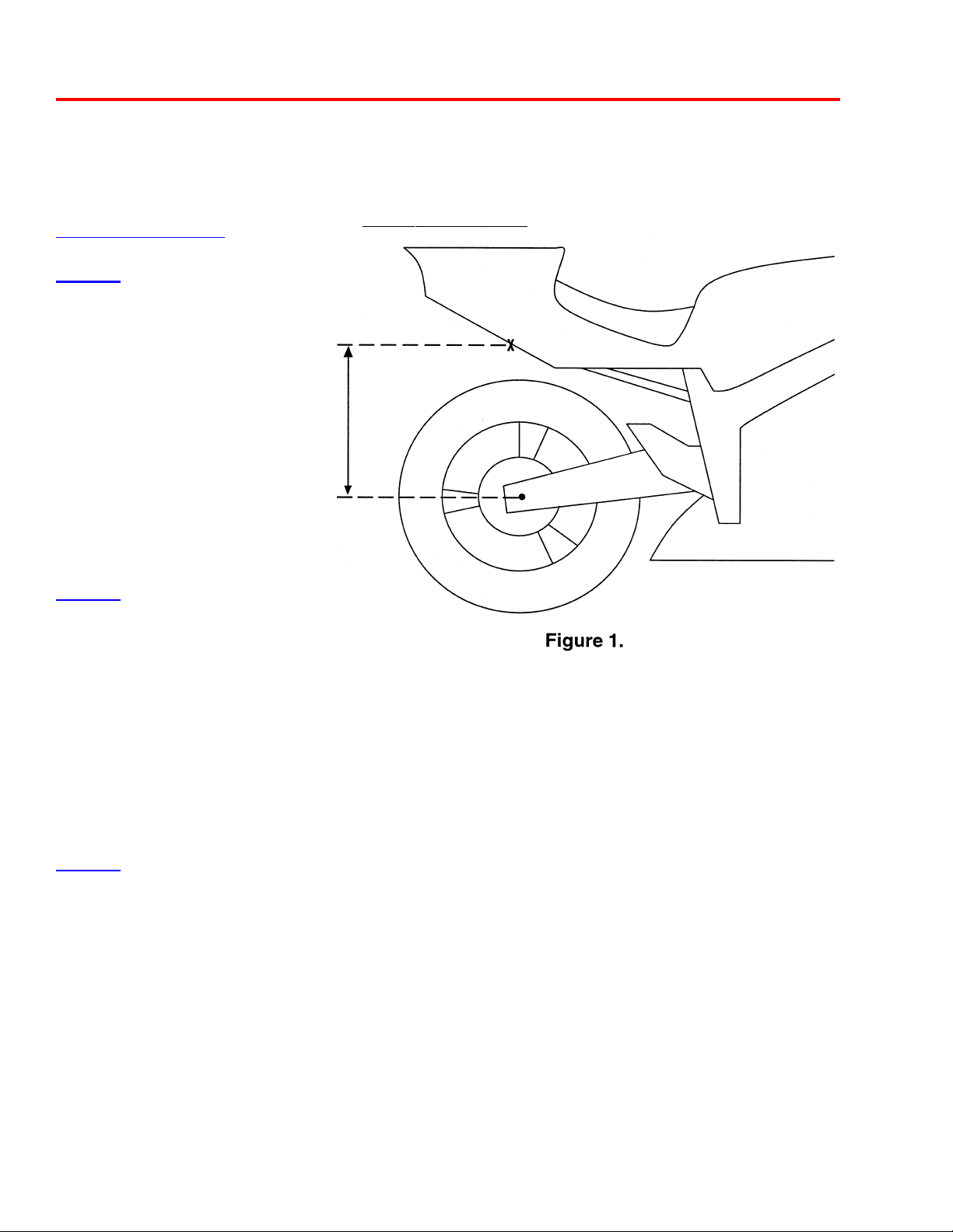
Setting the Sag*
STEP 1
1) Without a rider on the bike,
have an assistant lift the
rear of the motorcycle until
the rear wheel is off the
ground slightly.
2) Using a tape measure,
measure the distance
between the axle center line
and a convenient location
on the rear subframe
(Figure 1).
BUELL APPLICATIONS: Use Buell spring sag recommendations.
3) Record this measurement as "A".
STEP 2
1) This step requires the rider
and two additional people.
2) One person should hold the
front of the motorcycle, straddling
the front tire.
3) Have the rider, wearing all of their gear, sit on the bike in a tuck position.
4) The third person should then measure the distance between the axle center line and a convenient
location on the rear subframe (same locations used in Step 1).
5) Record this measurement as "B".
STEP 3
1) Subtract "B" from "A". This number is your sag.
The amount of sag required varies from rider to rider and from track to track.
The sag should be between 7/8" and 1 1/6".
If the sag is greater than 1 1/6", preload the spring by turning the adjustable spring collar.
If the sag is less than 7/8", remove preload by turning the adjustable spring collar.
2

Notes
3
Ride Height Adjustment
Adjusting Rear Ride Height
1. Loosen the jam nut with 1" wrench.
2. Adjust the eyelet length (shorter or longer). See #2 below.
3. Tighten the jam nut. See #3 below .
FOR BUELL AND FLA T TRACK
APPLICA TIONS ONLY!
Ride Height Affects
Going
length "eye to eye" will:
1. Raise the rear ride height.
LONGER with rear shock
WW
W
WW
WW
W
WW
#2
#3
.470" (12mm)
CAUTION!!!
DO NOT EXCEED
THIS LENGTH
Going SHORTER with rear shock
length "eye to eye" will:
1. Lower the rear ride height.
XX
X
XX
XX
X
XX
2. Transfer weight from the rear wheel
to the front wheel.
3. Make the front turn in quicker.
4. Reduce chain torque to the rear wheel.
4
2. Transfer more weight to the rear wheel.
3. Make the front turn in slower.
4. Increase chain torque to the rear wheel.

Adjustment Recommendations
Road Race Track Tuning: Symptoms and Suggestions
A. Change only one adjustment at a time, and send the rider out for evaluation and feedback.
B. Take notes: Keep track of rider comments, lap times, tire conditions, and current
weather conditions.
C. Be patient, go back to your original settings if you get lost.
Symptom: Tuning List:
Harsh over bumps: 1. Go softer with low speed compression, 2 to 4 clicks at a time
(counter clockwise)
2. Go softer with high speed compression, 1 to 2 clicks at a time.
3. Increase rear spring sag, -1/2 to 1 turn at a time on spring perch.
4. Change to a softer spring rate.
5. Note: Too soft on compression can bring about a harsh feeling by
allowing too much shock travel.
Excessive wheel spin
exiting corners: 1. Repeat above steps.
2. Rebound can be too fast, allowing the rear to unload and spin
the tire. Use caution when changing rebound.
Wallowing exiting corner: 1. Stiffen low speed compression (clockwise).
2. Stiffen high speed compression, 1 to 2 clicks at a time.
3. Decrease rear spring sag.
4. Slow down rebound, 1 to 2 clicks at a time (clockwise).
5. Change to a stiffer spring rate.
Slow turn-in: 1. Raise fork legs in triple clamps
2. Increase rear eyelet length, 1/2 to 1 turn at a time.
Cannot exceed 12mm of thread exposed.
3. Soften fork compression
4. Increase front fork sag
5. Speed-up rear rebound.
Mid corner push - front: 1. Stiffen rear low speed compression
2. Slow down fork rebound
5

8900 Series Shock Parts List
ITEM
NO.
10 JT-76HAT Jet, Top Hat
1 1 SP-15 Spring, (FF71)
12 JT-76POP Jet, Poppet
13 JT-RDHSNG Jet, Rebound, Straight Thru
14 NE-76 Needle
15 OR-2007-B O-Ring, 2-007, Buna 70
16 MR-8100 Metering Rod
17 NT-02R Ring Nut, 1/2" - 20
18 VS-__* Valve Stack
19 PB-55 Piston Band, 55mm
20 PI-____* Piston
21 OR-2028-B O-Ring, 2-028, Buna 70
PART
1 BD-81__* Body, Aluminum Coil-over (10.0" - 24.0")
2 RH-89225 Ride Height Adjuster, 8900, 2.25"
3 OR-2221-B O-Ring, 2-221, Buna 70
4 HO-87__* Hose (4" - 36" in 1" increments)
5 FT-__* Fitting, (45o or 90o), 1/8" NPT
6 BC-81__* Body Cap, 8100, (0o, 45o, 90o, 135o)
7 MO-8T Mono Ball, .500 ID, Teflon
8 RR-16 Retaining Ring, 1.025 Spiroloc
*
9 RR-05 Retaining Ring, .250 Internal
NO.
BC-89CL Body Cap, 8900 Clearance
MO-8T20 Mono Ball, .500 x .875 OD
MO-15T Monoball, 15mm ID x 1.00 OD
RR-10 Retaining Ring, .875 Spiroloc
JT-76RD
Jet, Rebound Complete (Includes items 9-13)
DESCRIPTION
The following parts
are in the rebound
adjuster for
Buell And C&J
Applications Only!
ITEM
NO.
22 VW-99 Top Out Pl ate, 1.375 x .504
23 BU-10DU06 Bushing, DU .625 x .375
24 BR-37 Bump Rubber, Top Out (Clear)
25 OR-2221-B O-Ring, 2-221, Buna 70
26 SB-89 Shaft Bearing, 8900
27 OR-2114-V O-Ring, 2-114, Viton 75
28 SL-09 Shaft Wiper, .625 Poly (Blue)
29 OR-2312-B O-Ring, 2-312, Buna 70
30 SH-_____* Shaft, Adjustable, (10.0" - 24.0")
31 NT-04J Jam Nut, 5/8" - 18
32 SR-89SRM Spring Retainer, 8900 Mount
33 CP-76RD Cap, Rebound Adjuster
34 KN-76RD Knob, Rebound Adjuster
35 OR-2017-B O-Ring, 2-017, Buna 70 Duro
36 OR-2017-B O-Ring, 2-017, Buna 70 Duro
37 DO-09 Dowel Pin, 1/8” x 1 1/8”
38 SM-89KB Shaft Mount, 8900, Knob Platform
39 NT-06J Jam Nut, 11/16" - 20
40 EY-89___* Eyelet, 8900, Motorcycle Model _____
41 SR-89225 Spring Retainer, 8900, 2.25"
42 RR-06 Wire Ring, .0625 Wire Diameter x 1.900
NOTE: Each shock also includes (1) BR-38 Bump Rubber, 38 gr.
ITEM
32 MR-89 Metering Rod, 8900
33 BU-04-BZ Bushing, .200 Bronze
34 SC-08 Screw, Socket Set, 8-32 x 3/8"
35 SP - 14 Spring, (A109)
36 BA-125-ST Ball, Steel 1/8"
37 SM-89 Shaft Mount, 8900, Adj. Platform
38 RS-89 Rebound Screw, 8900/Slotted
39 OR-2009-B O-Ring, 2-009, Buna 70 Duro
PART
NO.
*
AS-89SB
AS-89KBPLAT
*
CL-89___* Clevis, 8900, Motorcycle Model _____ (not shown)
PART NO.
Assembly, 8900 Shaft Bearing
(Includes items 23-28)
Assembly, 8900 Knob Platform
(Includes items 32-38)
DESCRIPTION
DESCRIPTION
6

8900 Series Shock Specifications
Body Cap Clocking
o
90
o
135
135
o
180
o
180
o
o
225
270
o
o
0
o
45
o
90
Body Cap Bushing
Total Width: ________ Bolt Diameter: ________
ÈÈ
Type of Adjuster ________________
45
315
o
o
0
o
__ 90o Fitting __ 45o Fitting
__ None
Extended
Length
(shortest)
Body Length
È
È
Stroke
È
Reservoir Clocking
o
90
o
135
o
180
o
225
o
270
315
o
45
o
0
o
È
Eyelet Bushing
Total Width: ________ Bolt Diameter: ________
__ 90o Fitting __ 45o Fitting
__ None
7
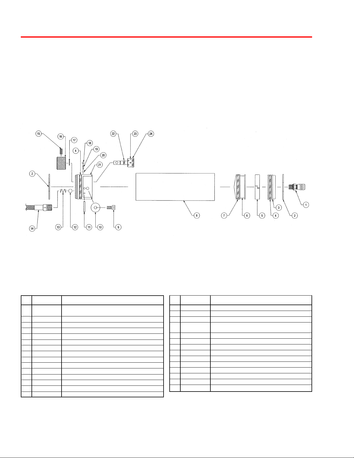
8981 Series Compression Adjuster Parts List
ITEM
NO.
PART
NO.
DESCRIPTION
8981 Series CD Adjuster Option
Available in 5.5" and 7" Body Lengths
1 IU-22-S Air Valve, Port O-Ring, Steel
IU-04 Valve Core, 2000 psi
IU-06 Valve Cap, High Temperature
OR-2010 O-Ring, 2-010, Buna 70
2 RR-06 Wire Ring, .0625 Wire Diameter x 1.900
3 CP-81R Cap, 8100 Reservoir
4 OR-2221-B O-Ring, 2-221, Buna 70
5 PB-55 Piston Band, 55mm
6 PI-81R Piston, Reservoir 1.72 Diameter
7 OR-2323-M O-Ring, 2-323, Moly 70
8 RB-81__* Reservoir Body, 8100, (5.50" or 7.00")
9 SC-24 Screw, SHCS, 10-24 x 3/8"
10 VW-03 Washer, Valve, .635 x .015 x .191
11 DO-04 Dowel Pin, 3/32" x 3/4"
8
ITEM
NO.
12 BA-250-ST Ball, Steel - 1/4"
13 SP-10 Spring, (TA2086)
14 HO-87__* Hose (4" - 36" in 1" increments)
15 SC-02 Screw, Socket Set, 8/32" x 3/8"
16 KN-81 Knob, CD 8100
17 RR-02 Retaining Ring, .250 External
18 SC-08 Screw, Socket Set, 8-32 x 1/8"
19 SP-14 Spring, (A109)
20 BA-125-ST Ball, Steel - 1/8"
21 HG-81D Housing, CD 8100 Dished
22 OR-2006-B O-Ring, 2-006, Buna 70
23 DR-81 Drum, CD 8100
24 OR-2013-B O-Ring, 2-013, Buna 70
* Incomplete Part Number
PART
NO.
AS-81UD Assembly, Update 8100 CD Adj with Knob
(Includes Items 4, 9-13, 15-24)
DESCRIPTION
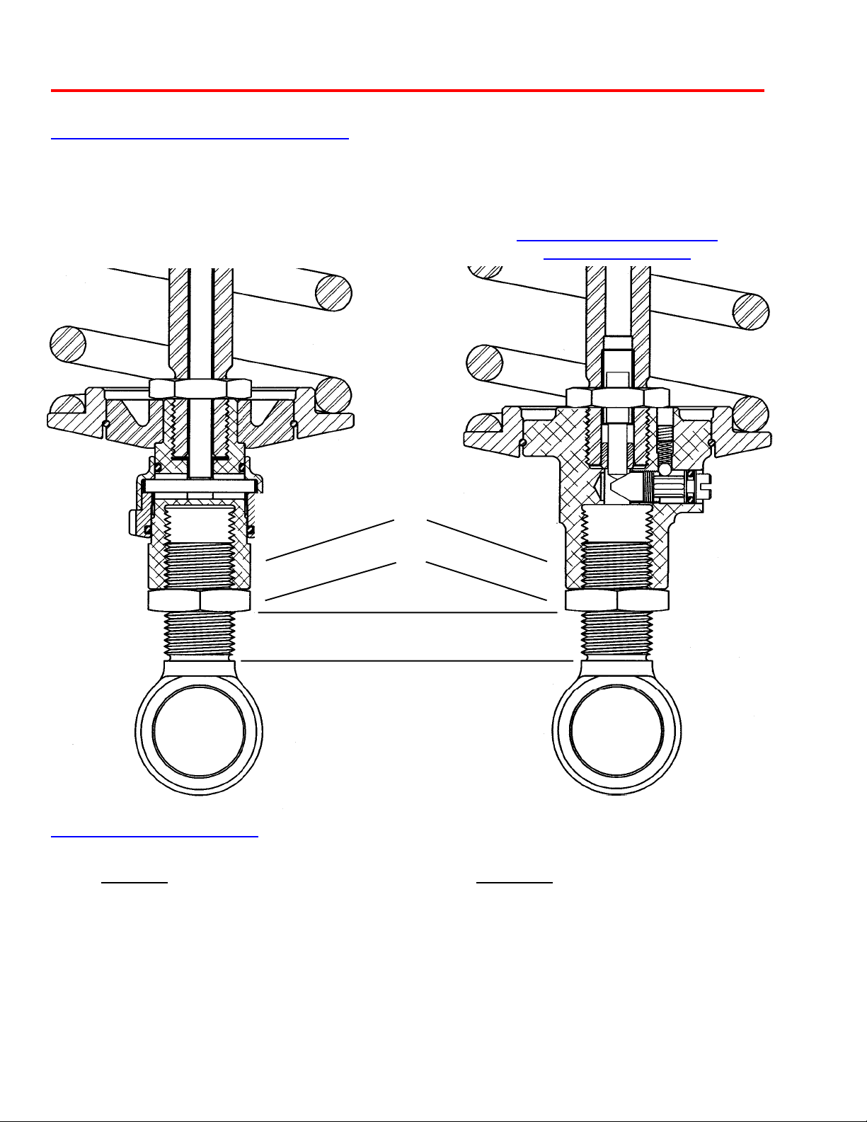
8981 Series Compression Adjuster
Low Speed High Speed
Figure 1
Figure 2
The 8981 compression adjuster is located in the remote reservoir
assembly . The remote reservoir serves as an extension of the shock
absorbers vital elements: oil and nitrogen. The remote reservoir theory
allows for the use of increased volumes of oil and nitrogen while
allowing for smaller shock packaging. Increased nitrogen volume is
essential for consistent damping forces throughout a long race and
extreme conditions.
In the compression mode of the shock absorber, fluid is forced into the
remote reservoir in direct proportion to the area of the shaft entering the
shock body. As fluid enters the reservoir, it must pass through the
compression adjuster. Inside the compression adjuster is the CD drum.
The CD drum has (6) settings, numbered (1-6), with number one setting
(the largest hole) being full soft and number six (the smallest hole)
being full firm. As fluid is forced through the CD drum (Figure 1), it is
metered through one of the preassigned orifices in the drum; it then
enters the reservoir body , moving the floating piston. The floating piston
is designed to separate the fluid and nitrogen, eliminating any chance
of aeration.
In the event of high speed shaft velocities, fluid passing through the
hole in the CD drum could pack-up, causing an increase in damping
forces, due to the fact that fluid can no longer pass through the hole.
In this event, the fluid forces open the blow-off valve (Figure 2). The
blow-off valve makes a more linear damping curve.
Note: The remote compression adjuster is a fine tuning device for the
main valving located inside the shock absorber.
9

8986 Series Compression Adjuster Parts List
ITEM
NO.
10 VW-01-C Crush Washer, .25 ID, Copper
11 PI-76CD Piston, Compression Adjuster
12 OR-2013-B O-Ring, 2-013, Buna 70
13 DO-06 Dowel Pin, 1/16" x 3/8"
14 BA-187-ST Ball, Steel - 3/16"
PART
NO.
8986 Series Adjuster Option
Available in 4", 5", and 6" Body Lengths
1 RR-12 Retaining Ring, .343 External
2 CA-92 Cage, CD Clasp .343 Diameter
3 RR-12 Retaining Ring, .343 External
4 CA-90 Cage, CD Top Hat .343 Diameter
5 VW-91 Washer , Valve, 1.475 x .010
VW-88 Washer, Valve, 1.350 x .008
VW-66 Washer, Valve, 1.200 x .006
VW-44 Washer, Valve, 1.050 x .004
VW-28 Washer, Valve, .900 x .008
VW-30 Washer, Valve, .900 x .010
VW-38 Washer, Valve, .900 x .020
6 CA-76CD Cage, Compression Adjuster
7 SC-76INS Screw, Piston Insert
8 VW-70 Washer , Valve, 1.200 x .010
9 SC-06 Screw, SHCS, 1/4" -20 x 3/4"
DESCRIPTION
10
ITEM
NO.
15 SP-16 Spring, (1460)
16 OR-2222-B O-Ring, 2-222, Buna 70
17 OR-2028-B O-Ring, 2-028, Buna 70
18 HG-76____* Housing, 8760, (Side Entry or Top Entry)
19 SP-14 Spring, (A109)
20 BA-125-ST Ball, Steel - 1/8"
21 OR-2013-B O-Ring, 2-013, Buna 70
22 SC-08 Screw, Socket Set, 8/32" x 1/8"
23 OR-2010-B O-Ring, 2-010, Buna 70
24 SH-86CD Shaft, CD High Speed
25 HO-87___* Hose (4" - 36" in 1" increments)
26 RB-76___* Reservoir Body, 8760, (4.00", 5.00" or 6.00")
27 PI-76 Piston, Floating 1.75 Diameter
28 OR-4222-B Quad Ring, 4-222, Buna 70
29 SL-87 Seal, Dowty
30 SC-18 Screw, SHCS, 4 - 40 x 1/4"
31 CP-76 Cap, Reservoir Port O-Ring
32 RR-06 Wire Ring, .0625 Wire Diameter x 1.900
33 OR-2010-B O-Ring, 2-010, Buna 70
34 IU-20-A Air Valve, Port O-Ring, Aluminum
* Incomplete Part Number
PART
NO.
IU-04 Valve Core, 2000 psi
IU-06 Valve Cap, High Temperature
DESCRIPTION

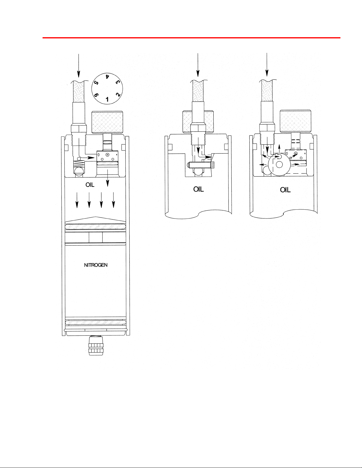
8986 Series Compression Adjuster
Fixed Low Speed Bleed Circuit
High Speed Flow Circuit
Compression Adjuster
COMPRESSION ADJUSTMENT
In the state of low shaft velocities (i.e. corner entry, exit, and power down), oil is displaced within the damper in
direct proportion to the volume of the shaft entering the body. The displaced fluid passes through the compression adjuster where it is metered through a fixed, low speed bleed orifice. Due to the small diameter of this
orifice and the viscosity of the damper fluid, a pressure loss occurs across the orifice. This loss of pressure is a
loss of energy in the fluid due to friction and the subsequent opposing damping force is generated.
As the shaft velocities increase, the same amount of fluid must pass through the low speed bleed orifice, but at
a much higher rate. The viscosity of the fluid causes a greater resistance to flow at the orifice entrance which in
turn produces a large internal force on the CD housing. The other major internal components, namely the piston
and shim cage, are designed to handle this extra force by allowing the shims to “blow off” proportionally to the
extra force generated, much like a coil spring compresses proportionally to the axial load applied. With this
arrangement, the low speed bleed orifice still meters fluid during high speed shaft movements, but the extra
forces generated are handled with the shims which have less resistance to flow at higher velocities. They are
designed to virtually bypass the low speed orifice and form a new fluid circuit. The force at which this occurs
can be varied by turning the compression adjuster in or out, which preloads the shims. Therefore, as the preload
on the shims increases, the static force required for them to activate is increased as well. The name designation
for the parts also clue one in to their purpose, with the low speed bleed orifice handling low velocity bleed flows
and the piston/shim arrangement handling high velocity flows. This principle originated in the main shaft piston/
shim arrangement and follows similar behavior.
NOTE: When making adjustments, use the full soft setting (adjuster wound all the way in against the reservoir
body) as a starting point when counting the number of “clicks” to the desired setting. The full soft setting should
correspond to a clicker number designation of 0. This starting datum has been proven to be most reliable and
repeatable when making compression adjustments. There are 22 +/- clicks of adjustment.
11
 Loading...