


7300 Series Parts List
ITEM |
PART |
DESCRIPTION |
|
NO. |
NO. |
||
|
|||
1 |
RR-16 |
Retaining Ring, 1.025 Spiroloc, Stainless |
|
2 |
MO-8T |
Monoball, .500 ID X 1.00 OD |
|
|
MO-15T |
Monoball, 15mm ID, Teflon |
|
|
AS-73BA |
Assembly, 7300 Body Complete (No Monoball) |
|
|
|
(Includes Items 3-11) |
|
3 |
IU-22-S |
Air Valve, Port O-Ring, S.S. |
|
|
IU-04 |
Valve Core, 2000 psi |
|
|
IU-06 |
Valve Cap, High Temperature |
|
4 |
OR-2010-B |
O-Ring, 2-010, Buna 70 |
|
5 |
BC-73 |
Body Cap, 7300 |
|
6 |
PI-73LFBV |
Piston, 7300 Floating Base Valve |
|
7 |
PB-WCFP |
Piston Band, WC Floating Piston |
|
8 |
OR-4226-B |
Quad Ring, 4-226, Buna 70 |
|
9 |
OR-2137-B |
O-Ring, 2-137, Buna 70 |
|
10 |
SC-73INS |
Screw, 7300, Body Insert |
|
11 |
BD-73 |
Body, 7300, 9.500" |
|
|
BD-739 |
Body, 7300, 10.500" |
|
|
BD-737 |
Body, 7300, 8.500” |
|
12 |
JT-76SL |
Jet, Compression Spring Sleeve |
|
13 |
JT-76POP |
Jet, Poppet |
|
14 |
SP-15 |
Spring, (FF71) |
|
15 |
JT-76HAT |
Jet, Top Hat |
|
16 |
JT-CDHSNG |
Jet, Compression Housing |
|
17 |
RR-05 |
Retaining Ring, .250 Internal |
|
18 |
JT-RDHSNG |
Jet, Rebound or Straight Thru |
|
19 |
NE-76 |
Needle |
ITEM |
PART |
DESCRIPTION |
|
NO. |
NO. |
||
|
|||
20 |
OR-2007 |
O-Ring, 2-007, Buna 70 |
|
21 |
MR-7318 |
Metering Rod, (7” = 7.775, 8” = 8.775, 9” = 9.775) |
|
22 |
NT-02R |
Ring Nut, .500 x 20 |
|
23 |
VS-___* |
Valve Stack |
|
24 |
PB-55 |
Piston Band, 55mm |
|
25 |
PI-______* |
Piston |
|
26 |
OR-2028-B |
O-Ring, 2-028, Buna 70 |
|
27 |
VW-99 |
Top Out Plate, 1.375 x .500 |
|
|
AS-76SB |
Assembly, Shaft Bearing Complete |
|
|
|
(Includes Items 27-31) |
|
28 |
BU-10DU10 |
Bushing, DU .625 x .625 |
|
29 |
OR-2221-B |
O-Ring, 2-221, Buna 70 |
|
30 |
SB-765 |
Shaft Bearing, 8760, 55mm |
|
31 |
OR-2114-V |
O-Ring, 2-114, Viton 75 |
|
32 |
SL-09 |
Shaft Wiper, .625 Poly (Blue) |
|
33 |
OR-2312-B |
O-Ring, 2-312, Buna 70 |
|
34 |
SH-____* |
Shaft, Adjustable, (6”, 7”, 8”, or 9”) |
|
35 |
NT-04J |
Jam Nut, .625 x 18 |
|
|
AS-WCEYELET |
Assembly, Eyelet Complete |
|
|
|
(Includes Items 35-39) |
|
36 |
CP-76RD |
Cap, Rebound Adjuster |
|
37 |
KN-76RD |
Knob, Rebound Adjuster |
|
38 |
EY-73KB |
Eyelet, Non Adjustable |
|
39 |
OR-2017-B |
O-Ring, 2-017 Buna 70 |
|
40 |
DO-09 |
Dowel Pin, 1/8” x 1 1/8” |
* Incomplete Part Number
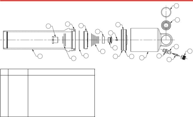
7300 Head Valve Body Assembly
|
|
|
|
|
|
|
1 |
|
17 |
|
|
|
|
|
2 |
19 |
|
15 |
9 |
|
|
|
|
|
|
|
13 |
11 |
|
|
|
|
|
|
|
|
|
|
|
|
|
|
|
12 |
|
|
5 |
|
|
|
14 |
|
|
3 |
|
|
|
|
|
|
|
||
20 |
|
18 |
16 |
10 |
8 |
7 |
6 |
|
|
|
|
|
4 |
||
|
|
|
|
|
|
|
ITEM |
PART |
DESCRIPTION |
|
NO. |
NO. |
||
|
|
|
AS-73HVBD9 |
Assembly, 7300 Head Valve Body 9.0 |
|
|
AS-73HVBD8 |
Assembly, 7300 Head Valve Body 8.0 |
|
1 |
RR-16 |
Retaining Ring, 1.025 Spiroloc, Stainless |
|
2 |
MO-8T |
Monoball, .500 ID X 1.00 OD |
|
3 |
IU-06 |
Valve Cap, High Temperature |
|
4 |
IU-04 |
Valve Core, 2000 psi |
|
5 |
IU-22-S |
Air Valve, Port O-Ring, S.S. |
|
6 |
OR-2010-B |
O-ring, 2-010 Buna 70 Duro |
|
7 |
BC-73 |
Body Cap, 7300 Series |
|
8 |
PB-WCFP |
Piston Band, 7300 Floating Piston |
|
9 |
PI-73LFBV |
Piston, 7300 Floating Base Valve |
ITEM |
PART |
DESCRIPTION |
|
NO. |
NO. |
||
|
|||
10 |
OR-4226-B |
Quad Ring, 4-226 Buna 70 Duro |
|
11 |
JT-___VB* |
Jet, V/B Piston (.000, .010, .015, .030, .040) |
|
12 |
SC-73HV |
Screw, 7300 Head Valve |
|
13 |
BU-73HV |
Bushing, 7300 Head Valve |
|
14 |
VS-__6* |
Valve Stack, .625 ID (AA - F) |
|
15 |
PI-73HV-125 |
Piston, 7300 Head Valve, 3 X .125 |
|
16 |
OR-2032-B |
O-ring, 2-032 Buna 70 Duro |
|
17 |
OR-2137-B |
O-ring, 2-137 Buna 70 Duro |
|
18 |
VW-1350__-625* |
Valve Washer, 1.350 X (.004 - .020) X .625 |
|
19 |
NT-73HV |
Nut, 7300 Head Valve |
|
20 |
BD-73_* |
Body, 7300 (6”, 7”, 8”, 9”) |
|
|
|
|
* Incomplete Part Number
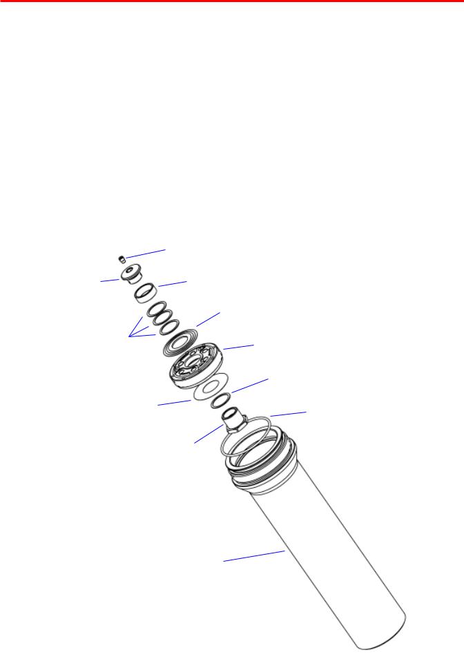
7300 Head Valve
Penske Racing Shocks would like to announce our new 7300 Removable Head Valve shock bodies. The new shock bodies include a female thread to accept the head valve piston or insert. These replace the one-piece head valve design and all non-head valve bodies.The new bodies come standard with an aluminum insert (P/N: SC-73INS) that maintains the piston bore the length of the body. If permitted by racing series rules, the insert may be removed, and the new removable head valve can be installed per the assembly instructions.
For reliability and safety reasons, Penske Racing Shocks requires that the new shock body design be used with either the supplied insert or the new removable head valve installed. The new shock bodies are not to be used without one of these items installed.
A removable head valve tool (P/N: TL-73INS) will be made available to all teams. This tool can be used to remove the supplied insert and install the new head valve. The assembly instructions shown below should be used when installing either the new head valve or the insert.
The new removable head valve design offers more tuning options and interchangeability than the previous design. The new bodies can be used with or without a head valve installed, allowing technicians to utilize one single body design for every application or track where two were needed previously. A shim rebound return has also been incorporated which increases rebound flow area and enhances damper response time during changes of stroke direction from compression to rebound. In addition, the new head valve assembly uses removable variable bleed jets (the same used in the Variable Bleed Pistons). The variable bleed jets can be interchanged quickly and easily (without disassembly of the head valve) and eliminates the need for drilling bleed holes in a poppet. A more tunable compression valve stack reduces the maximum base shim diameter to 1.350” for more efficient flow control and both head valve piston faces now include ½° of dishing.
These new features make the removable head valve shock more user-friendly, more universal, and a proven performance enhancement for professional racing teams!
CD SCREW
(160 in•lbs)
SC-73HV
CONSTANT SHIMS
REBOUND RETURN SHIMS (Ø.625 X 1.350”)
*recommended 1.350 x .004 (2)
.750 x .020 (1)
*Compression shim stack
+constant shims ≥ .100”
VARIABLE BLEED JET
JT-000VB JT-015
JT-030 JT-040
CD SPACER
BU-73HV
COMPRESSION SHIM STACK Ø.625 ID” (Ø1.350” BASE SHIM)
REMOVABLE HEAD VALVE (240 in•lbs)
PI-73HV-125
CONSTANT SHIM Ø.625 ID”
.750 X .020 (1)
O-RING
OR-2032-B
Grease for HV installation
CD NUT
NT-73HV
MAIN BODY
BD-737, 738 or 739

7300 Series Specifications |
|
|
|
|
|
|
S |
|
S |
|||
|
|
|
|
|
|
|
|
|
||||
|
|
|
|
|
|
|
|
|
|
|
|
|
|
Type |
Ext. Length |
Stroke |
Body Length |
|
|
|
|
|
|
|
|
5" |
Coilover Body with Head Valve (Sweep Adjuster) |
15.84" |
4" |
9.98" |
|
|
|
|
|
|
|
|
6" |
Coilover Body with Head Valve (Sweep Adjuster) |
17.84" |
5" |
10.98" |
|
|
|
|
|
|
|
|
7" |
Coilover Body with Head Valve (Sweep Adjuster) |
19.84" |
6" |
11.98" |
|
|
|
|
|
Body |
|
|
8" |
Coilover Body with Head Valve (Sweep Adjuster) |
21.84" |
7" |
12.98" |
|
|
|
|
|
Length |
|
|
9" |
Coilover Body with Head Valve (Sweep Adjuster) |
23.84" |
8" |
13.98" |
|
|
|
|
|
|
|
|
7" |
Smooth Body Non-Head Valve (Knob Adjuster) |
21.34" |
7" |
11.98" |
|
|
|
|
|
|
|
|
8" |
Smooth Body Non-Head Valve (Knob Adjuster) |
23.34" |
8" |
12.98" |
|
|
|
|
|
T |
|
|
|
|
|
|
|
|
|
|
|
|
|
|
|
9" |
Smooth Body Non-Head Valve (Knob Adjuster) |
25.34" |
9" |
13.98" |
|
|
||||||
|
S |
|
|
|
|
|
|
|||||
7" |
Smooth Body with Head Valve (Knob Adjuster) |
20.34" |
6" |
11.98" |
|
|
|
|
|
|
|
|
8" |
Smooth Body with Head Valve (Knob Adjuster) |
22.34" |
7" |
12.98" |
|
Stroke |
|
|
||||
|
|
|
|
|
|
|
|
|||||
9" |
Smooth Body with Head Valve (Knob Adjuster) |
24.34" |
8" |
13.98" |
|
|
||||||
|
|
|
|
|
|
|
|
|||||
|
|
|
|
|
|
|
|
|
|
|
|
|
*Also available in Non-Adjustable |
|
|
|
|
|
|
|
|
|
Extended |
||
|
|
|
|
|
|
|
|
|
|
|
||
|
|
|
|
|
|
|
|
|
|
|
|
Length |
Disassembly/Assembly Instructions |
T |
|
|
|
T |
|||||||
|
|
|||||||||||
|
|
|
|
|
|
|
|
|
|
|
|
|
Disassembly Instructions
1.Depressurize the shock after backing the adjuster to full soft.
2.Clamp the body cap eyelet in the vise with the shaft pointing up. Place overflow ring on body.
3.Unscrew the shaft bearing assembly from the shock body and remove the shaft assembly.
4.Drain the oil, when needed (if it contains excessive air bubbles). Please dispose of properly.
5.Clamp the shaft eyelet in the vise with the piston pointing up.
6.Remove the 3/4" ring nut to access valving or to change the seals in the shaft bearing.
7.Inspect and replace the damaged o-rings and wiper if needed.
Assembly Instructions
1.For revalving, refer to page 16 for additional information.
2.Reassemble the shaft, be sure that the piston is properly positioned. With the shaft still in the vise, the compression valve stack is on the bottom and the rebound on top. It is very important that the piston is positioned with the (6) concave ports facing up on the rebound side and the (3) concave ports facing down on the compression side, see the following page.
3.Torque the 3/4" ring nut to 25 ft•lbs (300 in•lbs).
4.If the jet was removed, torque to 120 in•lbs.
5.Pressurize the reservoir to reposition floating piston (approx. 50 lbs.). This step is very important.
6.Fill the shock body with oil* to the bottom of the threads. (1/2" from the top of the body)
*NOTE: Penske Suspension Fluid is recommended. Use of alternate fluids
may have an adverse effect on the damper's internal sealing components. (ie: o-rings)
7.Insert the shaft and piston assembly into the shock body and begin to work out the air bubbles trapped in the piston, by using 1"-2" strokes. Move the shaft up and down a few times, making sure the two port holes in the shaft always remain below the surface of the oil or air will be sucked back into the piston assembly. Lightly tap the eyelet with a mallet a few times to assure all the air bubbles are gone.
Note: this step is very important, repeat as needed.
8.Pull the shaft up until the two port holes in the shaft remain just below the surface of the oil.
9.Top off with oil and slide the shaft bearing down to seat the o-ring into the shock body without moving the shaft.
10.Depressurize the reservoir while asserting pressure to the shaft bearing and thread the shaft bearing into the shock body and tighten. Do not overtighten.
11.Pressurize to recommended nitrogen pressure for the specific track.

Suggested Maintenance
PRE RACE............................................................................................. |
Inspect for oil leakage. Check |
|
the nitrogen pressure. |
EVERY 2 RACES (500 MILES) ............................................................. |
Change oil. Replace the shaft seal |
|
o-ring, wiper, shaft bearing o-ring, |
|
and piston o-ring. |
YEARLY ................................................................................................. |
Replace the reservoir cap o-ring and |
|
floating piston quad ring. |
Trouble Shooting
LOSS OF NITROGEN PRESSURE ...................................................... |
Valve core is not tight or needs |
|
replacing, teflon seal on air valve |
|
needs replacing, reservoir cap |
|
o-ring needs replacing. |
OIL LEAK AROUND SHAFT ................................................................. |
Shaft seal o-ring or wiper needs |
|
replacing. Note: minimal oil |
|
seepage is normal. |
OIL LEAK BETWEEN SHAFT BEARING AND BODY ......................... |
Shaft bearing o-ring needs |
|
replacing or o-ring gland is damaged. |
SHAFT WILL NOT FULLY EXTEND ..................................................... |
Check for bent shaft, low nitrogen |
|
pressure, not enough oil. |
|
Note: do not spray brake cleaner or |
|
solvent on the shaft wiper, it may |
|
cause it to swell and prevent proper |
|
movement. |
NO CLICKS ON RED KNOB ADJUSTER ............................................ |
No Nitrogen pressure or broken pin or |
|
not enough oil in the shock. |
**DO NOT TRANSPORT CAR TO TRACK ON RACE SHOCKS. USE DESIGNATED SHOCKS, TOW SHOCKS, FOR TRANSPORTING.

Damping Adjusters
8760 Needle and Jet
The 8760 jet and needle combination have been designed to give the user a broader and more linear range of adjustment for bleed past the piston on rebound.
The 8760 jet utilizes a spring loaded poppet valve to check the flow. This gives a better seal against the flow and a quicker response time as the shaft changes direction.
This needle has a curved parabolic tip, which gives a very fine, linear adjustment in damping across the entire range provided by the jet. It can be thought of as a combination of the 10o, 5o, and 3o needles.
The 8760 needle and jet will fit any of our adjustable shafts, but they must be used together and cannot be interchanged with older style needles and jets.
The 8100 style (sweep) adjuster is located in the eyelet at the base of the main shaft. Inside the window is an adjustment screw, which serves as the control point for adjustments. (Figure 1)
The 8760 adjuster (red knob) is located at the base of the eyelet (Figure 2). During the compression or rebound stage of the shock movement, fluid is forced through two ports in the main shaft. Inside the main shaft is a needle and jet assembly, which adjusts the amount of fluid passing through the jet. By turning in the adjuster (clockwise), the needle is forced up into the jet, restricting the fluid, causing firmer damping forces. In reverse, by turning the adjuster out (counter clock-wise), more oil is allowed to pass through the jet causing lighter damping forces. The adjustment assembly, is a timed control for the shims located on the main piston to work.
*NOTE: All settings are taken from Full Hard.
i.e. -10 clicks = 10 clicks or sweeps (depending on adjuster) from Full Hard
+/- 25 sweeps -
+
|
|
|
|
Available Jets: |
|
ALL ADJUSTMENTS |
|
|
|
|
|
Rebound Jet |
|
||
|
|
|
|
|
ARE TAKEN FROM |
||
|
|
|
|
Compression Jet |
|
FULL HARD |
|
|
|
|
|
Open Jet |
|
|
|
|
|
|
|
Adj. .070 |
|
|
|
|
ADJUSTMENT |
|
|
Æ |
+/- 30 clicks |
||
|
|
|
|||||
SCREW |
|
|
|
|
|||
Æ |
|
|
|
|
|
|
ADJUSTER |
|
|
|
|
|
|
|
|
|
|
+ = |
More Damping |
|
|
KNOB |
|
|
|
- = |
Less Damping |
|
|
|
|
|
The range of adjustment is affected |
|
Figure 1 |
by the stiffness of the valve stack. |
Figure 2 |

General Valving Characteristics
High Speed |
Low Speed* |
High Speed |
Rebound |
Compression and Rebound |
Compression |
The damping characteristics of your shock are determined by the compression and rebound valve stacks located on the main piston.
The valve stacks are made up of a series of high quality shims, which are made to flex under the force of oil flowing through the piston ports and then return to their original state.
The thickness of the individual shims determines the amount of damping force the shock will produce. By changing the thickness of the individual shims, damping forces will be altered. For example, if you are running an “A” compression valving, where all the shims in the stack are .006 thick and you replace them with a “B” compression valving, which consists of all .008 thick shims, the compression damping will increase.
*When the shaft is moving very slowly oil passes through the bleed hole and/or shaft bleed, if there is one, before it passes to the shims.

A Guide To Damper Tuning
The ultimate purpose of a shock is to work together with the spring to keep the tire on the track. In compression (bump) to help control the movement of the wheel and in rebound to help absorb the stored energy of the compressed spring.
Breaking down the shaft speeds to chassis movement can be done from the data taken from on board acquisition and/or actual test sessions.
Where we find the biggest advantages with low speed adjusters is looking at the chassis in the plane of the four wheels in relation to chassis movement in roll and pitch and how quickly weight is transferred to each corner in order to load the tire sooner or later, depending on track conditions.
Usually in low grip situations allowing more bleed or less low speed damping is desirable to delay tire loading upon initial roll.
In high grip conditions adding damping or restricting bleed will load the tire sooner upon initial roll increasing platform stability.
In pitch situations on smooth surfaces under braking, increasing low speed damping or restricting bleed will help load the tires for entry or mid corner. If the tire begins bouncing under braking usually an increase in high speed compression will calm this down.
If the chassis feels like it is moving around too much between the plane of the wheels, increasing low speed damping or restricting bleed, will overall, firm up the chassis and give it a crisp feel or a better sense of feel in the car. This is why most drivers like this adjustment; as increasing low speed compression seems to give the driver better or quicker feedback from the chassis, resulting in a higher confidence in the car.
A car with too much low speed damping will usually lack grip in change of directions, cannot put power down in slower corners (wheel spin) and lack overall grip after initial turn in.
If traction is a problem coming off corners, reducing low speed damping or more bleed will help weight transfer at the rear thus increasing traction.
The range of adjustments will have a relationship to high or low shaft velocity, depending on what main piston is being used:
1)Linear Piston 1° - adjustment through range
2)Linear Piston 2° - greater change in low speed adjustment
3)Velocity Dependent Piston - adjustment through range with greater change in low speed
3)Digressive Piston - range primarily in low speed
Also depending on valving, there will be an affect on adjustment range. The softer the valving (A - B), the less force range it will have. This is due to a lower pressure required to blow the valves on the main piston. Obviously the heavier the valving (C - E), the more effective the bleed becomes. On digressive pistons, pre-load also affects the range of adjustment.
Rebound adjustments are usually indicated by the driver asking for more stability. By increasing low speed damping, stability will be enhanced; decreasing damping will allow more movement in the car, but will result in a little better tire wear.
Also, the amount of rebound can have a great influence on weight transfer. Less front rebound allows weight transfer to the rear under acceleration. Less rebound in the rear allows for a greater amount of weight transfer to the front under braking and turn in.
When a car is over damped in rebound it can pack down in a series of bumps and a driver will recognize this as too stiff and usually will think it is compression damping. Too much rebound can cause lack of grip on cornering.
When making a large spring change keep in mind where the rebound adjuster is and do you have enough range to compensate. Sometimes a spring change will bring a better balance to the damping values after the spring change. If the spring/shock combination was balanced, the rule of thumb is a stiffer spring requires lower compression and higher rebound. A softer spring requires higher compression and lower rebound.
|
Large Amplitude Change |
|
FORCE |
Small Amplitude Change |
FORCE |
|
|
VELOCITY (SHAFT SPEED)
LOW SPEED HIGH SPEED
Small Amplitude Change |
|
|
Large Amplitude Change |
VELOCITY (SHAFT SPEED) |
|
LOW SPEED |
HIGH SPEED |
LOW SPEED ADJUSTMENT EXAMPLE |
HIGH SPEED ADJUSTMENT EXAMPLE |
(BLEED) |
(SHIM) |
 Loading...