

Penske Racing Shocks 8760 User Manual

Adjustable Shocks Technical Manual
8100, 8660, 8760 Series
Main Office
150 Franklin St. • P.O. Box 1056
Reading, P A 19603
(610) 375-6180 • (610) 375-6190 Fax
Southeast Midwest
771-28 Fentress Blvd. • P.O. Box 11586 12666 US-12 • P.O. Box 666
Daytona Beach, FL 32120 Brooklyn, MI 49230
(386) 274-5336 • (386) 274-5442 Fax (517) 592-6681 • (517) 592-3696 Fax
T able of Contents Page
8100 Series Shock
Parts List ............................................................................................... 2
Damper Specifications and Part Lengths.............................................. 3
8760 Series Shock
Parts List ............................................................................................... 4
Damper Specifications and Part Lengths.............................................. 5
8100 Series Compression Adjuster
Parts List ............................................................................................... 6
Operational Guide ................................................................................. 7
8660 Series Compression Adjuster
Parts List ............................................................................................... 8
Operational Guide ................................................................................. 9
8760 Series Compression Adjuster
Parts List ............................................................................................... 10
Operational Guide ................................................................................. 11
Rebound Adjusters.................................................................................... 12
Disassembly / Assembly Instructions ..................................................... 13
Suggested Maintenance ........................................................................... 14
Trouble Shooting ....................................................................................... 14
Valving
General Valving Characteristics............................................................. 15
A Guide To Damper Tuning................................................................... 16
Basic Start-up Procedure...................................................................... 17
Valve S tacks.......................................................................................... 18
VDP and Digressive V alving Information Options.................................. 19
VDP 55mm Linear Base Shim .............................................................. 19
Preload Shim Spacers........................................................................... 19
Pistons
Flow Rate Through Multiple Bleed Holes .............................................. 20
Piston Selection .................................................................................... 21
Linear Piston ......................................................................................... 22
Digressive Piston................................................................................... 23
Velocity Dependent Piston (VDP) ......................................................... 24
Damping Adjustments........................................................................... 26
REV: 3/27/01
#5
Dyno Graph Overview ............................................................................... 28
Notes ........................................................................................................... 32
1

8100 Series Parts List
ITEM
NO.
PART
NO.
DESCRIPTION
Aluminum Coil-over
Double Adjustable
1 BD-81__* Body, Aluminum Coil-over (10.0" - 24.0")
2 RH-812__* Ride Height Adjuster, 8100, (2.25" or 2.50")
3 OR-2221-B O-Ring, 2-221, Buna 70
4 HO-87__* Hose (4" - 36" in 1" increments)
5 FT-__* Fitting, (45o or 90o), 1/8" NPT
6 BC-81__* Body Cap, 8100, (0o, 45o, 90o, 135o)
7 MO-8T Mono Ball, .500 ID, Teflon
MO-15T Monoball, 15mm ID, Teflon
8 RR-16 Retaining Ring, 1.025 Spiroloc
JT-76RD Jet, Rebound Complete
9 RR-05 Retaining Ring, .250 Internal
10 JT-76HAT Jet, Top Hat
11 SP-15 Spring, (FF71)
12 JT-76POP Jet, Poppet
13 JT-RDHSNG Jet, Rebound, Straight Thru
14 NE-76 Needle
15 OR-2007-B O-Ring, 2-007, Buna 70
16 MR-8100 Metering Rod
17 NT-02R Ring Nut, .500 x 20
(Includes Items 9-13)
2
ITEM
NO.
18 VS-__* Valve S tack
19 PB-55 Piston Band, 55mm
20 PI-____* Piston
21 OR-2028-B O-Ring, 2-028, Buna 70
22 VW-99 Top Out Plate, 1.375 x .500
23 BU-10DU10 Bushing, DU .625 x .625
24 OR-2221-B O-Ring, 2-221, Buna 70
25 SB-765 Shaft Bearing, 55mm
26 OR-21 14-V O-Ring, 2-114, Viton 75
27 SL-09 Shaft W iper, .625 Poly (Blue)
28 OR-2312-B O-Ring, 2-312, Buna 70
29 SH-_____* Shaft, Adjustable, (10.0" - 24.0")
30 RS-81 Rebound Screw, Adjustable Shaft
31 OR-2008-B O-Ring, 2-008, Buna 70
32 SR-812__* Spring Retainer, 8100, (2.25" or 2.50")
33 NT-04J Jam Nut, .625 x 18
34 EY - 81 160 Eyelet, 1.60 Sweep, 0
See Pages 6 and 7 for 8100 Series Adjuster.
* Incomplete Part Number
PART
NO.
AS-76SB Assembly, Shaft Bearing Complete
EY -81 1690 Eyelet, 1.60 Sweep, 90
EY -81200 Eyelet, 2.00 Sweep, 0
EY -81230 Eyelet, 2.30 Sweep, 0
(Includes Items 23-27)
DESCRIPTION
o
o
o
o
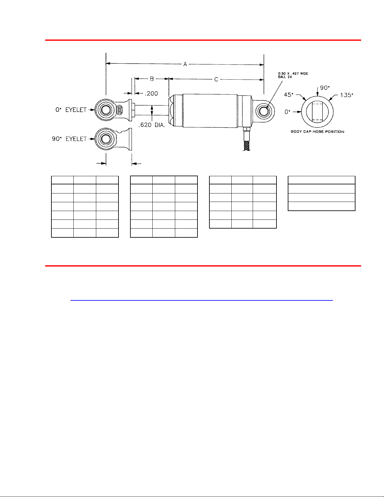
8100 Damper Specifications
D
ABC
10.0 2.125 6.075
10.5 2.375 6.325
11.0 2.625 6.575
11.5 2.875 6.825
12.0 3.125 7.075
12.5 3.375 7.325
ABC
13.0 3.625 7.575
13.5 3.875 7.825
14.0 4.125 8.075
14.5 4.375 8.325
15.0 4.625 8.575
15.5 4.875 8.825
8100 Series Part Lengths
SH-___A BD-81___
Part Shock Shaft Metering Body
Suffix Size Length Rod Length Length
100 10.0” 5.625 1.750 4.275
105 10.5” 5.875 2.000 4.525
110 11.0” 6.125 2.250 4.775
115 11.5” 6.375 2.500 5.025
120 12.0” 6.625 2.750 5.275
125 12.5” 6.875 3.000 5.525
130 13.0” 7.125 3.250 5.775
135 13.5” 7.375 3.500 6.025
140 14.0” 7.625 3.750 6.275
145 14.5” 7.875 4.000 6.525
150 15.0” 8.125 4.250 6.775
155 15.5” 8.375 4.500 7.025
160 16.0” 8.625 4.750 7.275
175 17.5” 9.375 5.500 8.025
180 18.0” 9.625 5.750 8.275
200 20.0” 10.500 6.625 9.400
220 22.0” 11.500 7.625 10.400
240 24.0” 12.500 8.625 11.400
ABC
16.0 5.125 9.075
17.5 5.875 9.875
18.0 6.125 10.075
20.0 7.125 11.075
24.0 9.125 13.075
D
1.6 (0o or 90o) (std.)
2.0 (0o)
2.3 (0o)
3
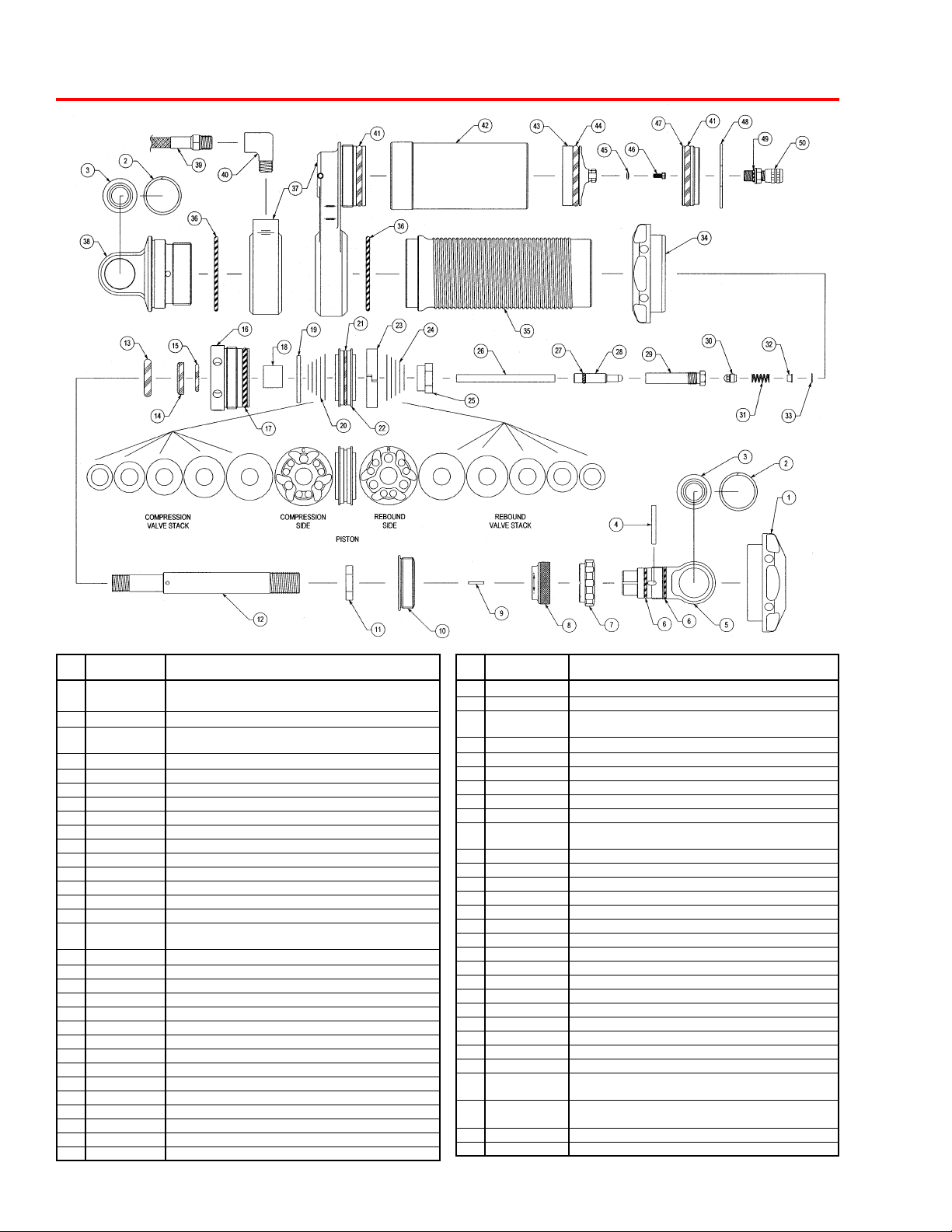
8760 Series Parts List
ITEM
NO.
PART
NO.
DESCRIPTION
8760 Aluminum Coil-over (Piggyback)
8760 Aluminum Coil-over (Remote Reservoir)
1 SR-762__* Spring Retainer, 8760, (2.00", 2.25" or 2.50")
AS-76EY__* Assembly, 8760 Eyelet Complete (2.1”, 2.3”,2.6”)
2 RR-10 Retaining Ring, .875 Spiroloc
3 MO-8T20 Monoball, .500 ID x .875 OD
4 DO-09 Dowel Pin, 1/8" x 1 1/8"
5 EY-76__* Eyelet, 8760, (2.10", 2.30", or 2.60")
6 OR-2017-B O-Ring, 2-017, Buna 70
7 KN-76RD Knob, Rebound Adjuster
8 CP-76RD Cap, Rebound Adjuster
9 DO-06 Dowel Pin, 1/16" x 3/8"
10 SR-76SRM Spring Retainer, 8760, Mount
11 NT-12J Jam Nut, .562 x 18
12 SH-76___* Shaft, 8760, (10.0" - 24.0")
13 OR-2312-B O-Ring, 2-312, Buna 70
AS-76SB__* Assembly, 8760 Shaft Bearing (45mm, 55mm)
14 SL-09 Shaft W iper, .625 Poly (Blue)
15 OR-21 14-V O-Ring, 2-114, Viton 75
16 SB-76_ Shaft Bearing, 8760, (45mm or 55mm)
17 OR-2221-B O-Ring, 2-221, Buna 70 (55mm)
OR-2219-B O-Ring, 2-219, Buna 70 (45mm)
18 BU-10DU10 Bushing, DU .625 x .625
19 VW-99 Top Out Plate, 1.375 x .500
20 VS-___* Valve Stack
21 OR-2025-B O-Ring, 2-025, Buna 70 (45mm)
OR-2028-B O-Ring, 2-028, Buna 70 (55mm)
22 PI-____* Piston
23 PB-___* Piston Band, (45mm or 55mm)
24 VS-___* Valve Stack
25 NT-02R Ring Nut, .500 x 20
26 MR-8760 Metering Rod
(Includes Items 2-8)
(Includes Items 14-18)
4
ITEM
NO.
27 OR-2007-B O-Ring, 2-007, Buna 70
28 NE-76 Needle
29 JT-RDHSNG Jet, Rebound, Straight Thru
30 JT-76POP Jet, Poppet
31 SP-15 Spring, (FF71)
32 JT-76HAT Jet, Top Hat
33 RR-05 Retaining Ring, .250 Internal
34 RH-762__* Ride Height Adjuster, 8760, (2.00", 2.25" or 2.50")
35 BD-76___* Body, 8760, (55mm, 10.0" - 24.0")
36 OR-2136-B O-Ring, 2-136, Buna 70 (55mm)
37 HG-76PB___* Housing, Piggyback, (45mm or 55mm)
38 BC-76___* Body Cap,8760, (45mm or 55mm)
39 HO-87__* Hose (4" - 36" in 1" increments)
40 FT-__* Fitting, (45o or 90o), 1/8" NPT
41 OR-2222-B O-Ring, 2-222, Buna 70
42 RB-76_* Reservoir Body, 8760, (4.00", 5.00" or 6.00")
43 PI-76 Piston, Floating, 1.75 Diameter
44 OR-4222-B Quad Ring, 4-222, B-70
45 SL-87 Seal, Dowty
46 SC-18 Screw, SHCS, 4-40 x 1/4"
47 CP-76 Cap, Reservoir Port O-Ring
48 RR-06 Wire Ring, .0625 Wire Diameter x 1.900
49 OR-2010-B O-Ring, 2-010, Buna 70
50 IU-20-A Air Valve, Port O-Ring, Aluminum
See Pages 8-11 for 8660 and 8760 Series Adjuster.
* Incomplete Part Number
PART
NO.
JT-76RD Jet, Rebound Complete
OR-2133-B O-Rint, 2-133, Buna 70 (45mm)
CO-76____* Collar, Body, (45mm or 55mm)
BC-76E___* Body Cap, 8760, Extended (.250”,.500”,1.00”) 55mm
AS-76RESCAP Assembly, 8760 Reservoir Cap
IU-04 Valve Core, 2000 psi
IU-06 Valve Cap, High Temperature
(Includes Items 29-33)
(Includes Items 47, 41, 49, 50)
DESCRIPTION
(45mm, 10.0" - 13.5")
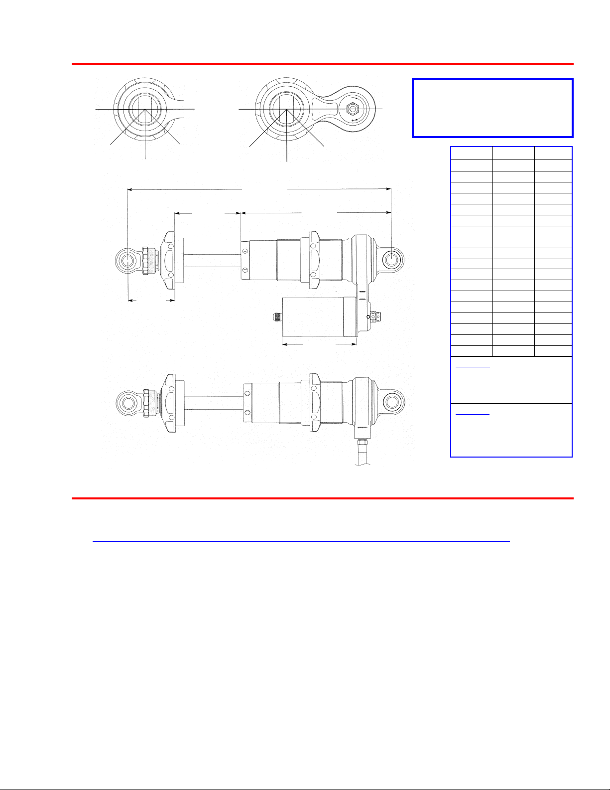
8760 Series Damper Specifications
o
0
180
o
o
0
180
o
45mm (1.87 OD) = 2.00” ID
Spring Hardware
55mm (2.06 OD) = 2.25” or 2.50” ID
Spring Hardware
o
45
o
90
135
o
o
45
o
90
135
o
DIM “A” DIM “B” DIM “C”
10.0 1.875 5.850
10.5 2.125 6.100
1 1.0 2.375 6.350
1 1.5 2.625 6.600
12.0 2.875 6.850
12.5 3.125 7.100
DIM “B”
Stroke
DIM “A”
Eye to Eye
DIM “C”
Body Length
13.0 3.375 7.350
13.5* 3.625 7.600
14.0 3.875 7.850
14.5 4.125 8.100
15.0 4.375 8.350
15.5 4.625 8.600
Dim “E”
16.0 4.875 8.850
17.5 5.625 9.600
18.0 5.875 9.850
20.0 6.875 10.850
DIM “D”
Reservoir Length
22.0 7.875 11.850
24.0 8.875 12.850
DIM “D”
4.00
5.00
6.00
DIM “E”
2.277 for 2.100 Eyelet (std.)
2.477 for 2.300 Eyelet
2.777 for 2.600 Eyelet
* 13.5 (DIM “A”) max for 45mm
8760 Series Part Lengths
SH-76___ BD-76___
Part Overall Shaft Metering Body
Suffix Length Length Rod Length Length
100 10.0” 5.250 2.525 3.915
105 10.5” 5.550 2.775 4.165
110 11.0” 5.750 3.025 4.415
115 11.5” 6.000 3.275 4.665
120 12.0” 6.250 3.525 4.915
125 12.5” 6.500 3.775 5.165
130 13.0” 6.750 4.025 5.415
135 13.5” 7.000 4.275 5.665
140 14.0” 7.250 4.525 5.915
145 14.5” 7.500 4.775 6.165
150 15.0” 7.750 5.025 6.415
155 15.5” 8.000 5.275 6.665
160 16.0” 8.250 5.525 6.915
175 17.5” 9.000 6.275 7.665
180 18.0” 9.250 6.525 7.915
200 20.0” 10.250 7.525 8.915
220 22.0” 11.250 8.525 9.915
240 24.0” 12.250 9.525 10.915
5
8100 Series Compression Adjuster Parts List
ITEM
NO.
PART
NO.
DESCRIPTION
8100 Series CD Adjuster Option
Available in 5.5" and 7" Body Lengths
1 IU-22-S Air Valve, Port O-Ring, Steel
IU-04 Valve Core, 2000 psi
IU-06 Valve Cap, High Temperature
OR-2010 O-Ring, 2-010, Buna 70
2 RR-06 Wire Ring, .0625 Wire Diameter x 1.900
3 CP-81R Cap, 8100 Reservoir
4 OR-2221-B O-Ring, 2-221, Buna 70
5 PB-55 Piston Band, 55mm
6 PI-81R Piston, Reservoir 1.72 Diameter
7 OR-2323-M O-Ring, 2-323, Moly 70
8 RB-81__* Reservoir Body, 8100, (5.50" or 7.00")
9 SC-24 Screw, SHCS, 10-24 x 3/8"
10 VW-03 Washer, V alve, .635 x .015 x .191
11 DO-04 Dowel Pin, 3/32" x 3/4"
6
ITEM
NO.
12 BA-250-ST Ball, Steel - 1/4"
13 SP-10 Spring, (TA2086)
14 HO-87__* Hose (4" - 36" in 1" increments)
15 SC-02 Screw, Socket Set, 8/32" x 3/8"
16 KN-81 Knob, CD 8100
17 RR-02 Retaining Ring, .250 External
18 SC-08 Screw, Socket Set, 8-32 x 1/8"
19 SP-14 Spring, (A109)
20 BA-125-ST Ball, Steel - 1/8"
21 HG-81D Housing, CD 8100 Dished
22 OR-2006-B O-Ring, 2-006, Buna 70
23 DR-81 Drum, CD 8100
24 OR-2013-B O-Ring, 2-013, Buna 70
* Incomplete Part Number
PART
NO.
AS-81UD Assembly, Update 8100 CD Adj with Knob
(Includes Items 4, 9-13, 15-24)
DESCRIPTION
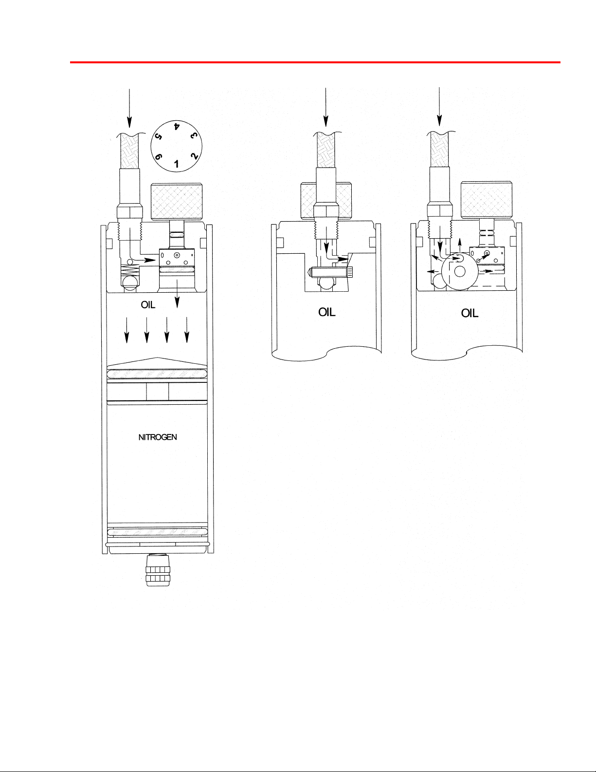
8100 Series Compression Adjuster
Figure 1
Figure 2
The 8100 compression adjuster is located in the remote reservoir
assembly. The remote reservoir serves as an extension of the shock
absorbers vital elements: oil and nitrogen. The remote reservoir
theory allows for the use of increased volumes of oil and nitrogen
while allowing for smaller shock packaging. Increased nitrogen
volume is essential for consistent damping forces throughout a long
race and extreme conditions.
In the compression mode of the shock absorber, fluid is forced into
the remote reservoir in direct proportion to the area of the shaft
entering the shock body. As fluid enters the reservoir, it must pass
through the compression adjuster. Inside the compression adjuster is
the CD drum. The CD drum has (6) settings, numbered (1-6), with
number one setting (the largest hole) being full soft and number six
(the smallest hole) being full firm. As fluid is forced through the CD
drum (Figure 1), it is metered through one of the preassigned orifices
in the drum; it then enters the reservoir body,moving the floating
piston. The floating piston is designed to separate the fluid and
nitrogen, eliminating any chance of aeration.
In the event of high speed shaft velocities, fluid passing through the
hole in the CD drum could pack-up, causing an increase in damping
forces, due to the fact that fluid can no longer pass through the hole.
In this event, the fluid forces open the blow-off valve (Figure 2). The
blow-off valve makes a more linear damping curve.
Note: The remote compression adjuster is a fine tuning device for the
main valving located inside the shock absorber.
7
8660 Series Compression Adjuster Parts List
ITEM
NO.
10 VW-01-C Crush Washer, .25 ID, Copper
11 PI-76CD Piston, Compression Adjuster
12 OR-2013-B O-Ring, 2-013, Buna 70
13 DO-06 Dowel Pin, 1/16" x 3/8"
14 BA-187-ST Ball, Steel - 3/16"
PART
NO.
Available in 4", 5", and 6" Body Lengths
1 RR-12 Retaining Ring, .343 External
2 CA-92 Cage, CD Clasp .343 Diameter
3 RR-12 Retaining Ring, .343 External
4 CA-90 Cage, CD Top Hat .343 Diameter
5 VW-91 Washer , Valve, 1.475 x .010
VW-88 Washer, V alve, 1.350 x .008
VW-66 Washer, V alve, 1.200 x .006
VW-44 Washer, V alve, 1.050 x .004
VW-28 Washer, V alve, .900 x .008
VW-30 Washer, V alve, .900 x .010
VW-38 Washer, V alve, .900 x .020
6 CA-76CD Cage, Compression Adjuster
7 SC-76INS Screw, Piston Insert
8 VW-70 Washer , Valve, 1.200 x .010
9 SC-06 Screw, SHCS, 1/4" -20 x 3/4"
DESCRIPTION
8660 Series Adjuster Option
ITEM
NO.
15 SP-16 Spring, (1460)
16 OR-2222-B O-Ring, 2-222, Buna 70
17 OR-2028-B O-Ring, 2-028, Buna 70
18 HG-76____* Housing, 8760, (Side Entry or Top Entry)
19 SP-14 Spring, (A109)
20 BA-125-ST Ball, Steel - 1/8"
21 OR-2013-B O-Ring, 2-013, Buna 70
22 SC-08 Screw, Socket Set, 8/32" x 1/8"
23 OR-2010-B O-Ring, 2-010, Buna 70
24 SH-86CD Shaft, CD High Speed
25 HO-87___* Hose (4" - 36" in 1" increments)
26 RB-76___* Reservoir Body, 8760, (4.00", 5.00" or 6.00")
27 PI-76 Piston, Floating 1.75 Diameter
28 OR-4222-B Quad Ring, 4-222, Buna 70
29 SL-87 Seal, Dowty
30 SC-18 Screw, SHCS, 4 - 40 x 1/4"
31 CP-76 Cap, Reservoir Port O-Ring
32 RR-06 Wire Ring, .0625 Wire Diameter x 1.900
33 OR-2010-B O-Ring, 2-010, Buna 70
34 IU-20-A Air Valve, Port O-Ring, Aluminum
* Incomplete Part Number
PART
NO.
IU-04 Valve Core, 2000 psi
IU-06 Valve Cap, High Temperature
DESCRIPTION
8
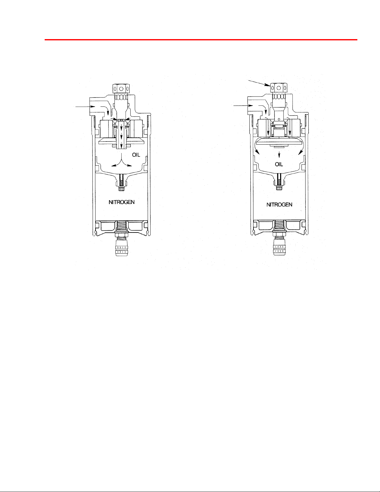
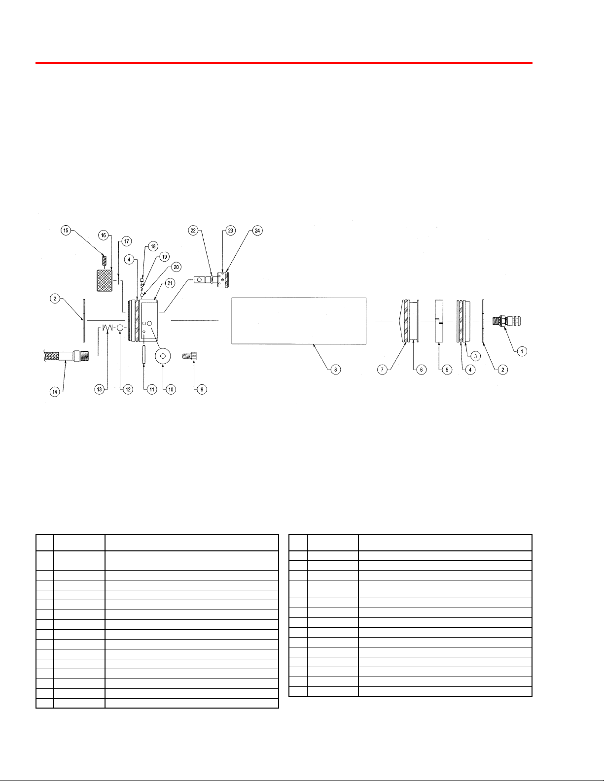
8660 Series Compression Adjuster
Fixed Low Speed Bleed Circuit
High Speed Flow Circuit
Compression Adjuster
COMPRESSION ADJUSTMENT
In the state of low shaft velocities (i.e. corner entry, exit, and power down), oil is displaced within the damper in
direct proportion to the volume of the shaft entering the body. The displaced fluid passes through the compression adjuster where it is metered through a fixed, low speed bleed orifice. Due to the small diameter of this
orifice and the viscosity of the damper fluid, a pressure loss occurs across the orifice. This loss of pressure is a
loss of energy in the fluid due to friction and the subsequent opposing damping force is generated.
As the shaft velocities increase, the same amount of fluid must pass through the low speed bleed orifice, but at
a much higher rate. The viscosity of the fluid causes a greater resistance to flow at the orifice entrance which in
turn produces a large internal force on the CD housing. The other major internal components, namely the piston
and shim cage, are designed to handle this extra force by allowing the shims to “blow off” proportionally to the
extra force generated, much like a coil spring compresses proportionally to the axial load applied. With this
arrangement, the low speed bleed orifice still meters fluid during high speed shaft movements, but the extra
forces generated are handled with the shims which have less resistance to flow at higher velocities. They are
designed to virtually bypass the low speed orifice and form a new fluid circuit. The force at which this occurs
can be varied by turning the compression adjuster in or out, which preloads the shims. Therefore, as the preload
on the shims increases, the static force required for them to activate is increased as well. The name designation
for the parts also clue one in to their purpose, with the low speed bleed orifice handling low velocity bleed flows
and the piston/shim arrangement handling high velocity flows. This principle originated in the main shaft piston/
shim arrangement and follows similar behavior.
NOTE: When making adjustments, use the full soft setting (adjuster wound all the way in against the reservoir
body) as a starting point when counting the number of “clicks” to the desired setting. The full soft setting should
correspond to a clicker number designation of 0. This starting datum has been proven to be most reliable and
repeatable when making compression adjustments. There are 22 +/- clicks of adjustment.
9
8760 Series Compression Adjuster Parts List
ITEM
NO.
10 VW-01-C Crush Washer, .25 ID, Copper
11 PI-76CD Piston, Compression Adjuster
12 OR-2013-B O-Ring, 2-013, Buna 70
13 DO-06 Dowel Pin, 1/16" x 3/8"
14 BA-187-ST Ball, Steel - 3/16"
15 SP-16 Spring, (1460)
16 OR-2222-B O-Ring, 2-222, Buna 70
17 OR-2028-B O-Ring, 2-028, Buna 70
PART
NO.
Available in 4", 5", and 6" Body Lengths
1 J T -76CDSH Jet, High Speed Shaft
2 RR-12 Retaining Ring, .343 External
3 CA-92 Cage, CD Clasp .343 Diameter
4 CA-90 Cage, CD Top Hat .343 Diameter
5 VW-91 Washer , Valve, 1.475 x .010
VW-88 Washer, V alve, 1.350 x .008
VW-66 Washer, V alve, 1.200 x .006
VW-44 Washer, V alve, 1.050 x .004
VW-28 Washer, V alve, .900 x .008
VW-30 Washer, V alve, .900 x .010
VW-38 Washer, V alve, .900 x .020
6 CA-76CD Cage, Compression Adjuster
7 SC-76INS Screw, Piston Insert
8 VW-70 Washer , Valve, 1.200 x .010
9 SC-06 Screw, SHCS, 1/4" -20 x 3/4"
DESCRIPTION
8760 Series Adjuster Option
ITEM
NO.
18 HG-76____* Housing, 8760, (Side Entry or Top Entry)
19 SP-14 Spring, (A109)
20 BA-125-ST Ball, Steel - 1/8"
21 OR-2013-B O-Ring, 2-013, Buna 70
22 SC-08 Screw, Socket Set, 8/32" x 1/8"
23 OR-2010-B O-Ring, 2-010, Buna 70
24 SH-76CD12 Shaft, CD High Speed 12pt
25 DO-18 Roll Pin, 1/16" x 1/2"
26 OR-2004-B O-Ring, 2-004, Buna 70
27 SC-76CDLS Screw, CD Low Speed
28 BA-093-ST Ball, Steel - 3/32"
29 SP-12 Spring, (3648)
30 HO-87__* Hose (4" - 36", in 1" increments)
31 RB-76__* Reservoir Body, 8760, (4.00", 5.00", or 6.00")
32 PI-76 Piston, Floating 1.75 Diameter
33 OR-4222-B Quad Ring, 4-222, Buna 70
34 SL-87 Seal, Dowty
35 SC-18 Screw, SHCS, 4 - 40 x 1/4"
36 CP-76 Cap, Reservoir Port O-Ring
37 RR-06 Wire Ring, .0625 Wire Diameter x 1.900
38 OR-2010-B O-Ring, 2-010, Buna 70
39 IU-20-A Air Valve, Port O-Ring, Aluminum
* Incomplete Part Number
PART
NO.
IU-04 Valve Core, 2000 psi
IU-06 Valve Cap, High Temperature
DESCRIPTION
10
 Loading...