

Pella Insynctive Product Manual

PELLA® INSYNCTIVE™ PRODUCT GUIDE
ENTRY DOOR
DEADBOLT SENSOR
ENTRY DOOR DEADBOLT SENSOR communicates the status
(locked or unlocked and opened or closed) of an Entry Door
from Pella to Pella Insynctive BRIDGE.
WHAT’S NEEDED:
• PELLA INSYNCTIVE BRIDGE (required — sold separately): Wirelessly connects your Insynctive
products to STATUS INDICATOR or a compatible security or home automation system.
• PELLA INSYNCTIVE STATUS INDICATOR (optional — sold separately): Indicates status of Pella
Insynctive SENSORS. You can also use a compatible security or home automation system to
monitor your entry door.
• ARCHITECT SERIES® OR PELLA FIBERGLASS OR STEEL ENTRY DOOR PREPPED FOR
ENTRY DOOR DEADBOLT SENSOR
• FLATHEAD SCREWDRIVER
• PHILLIPS-HEAD SCREWDRIVER
• DRILL AND 1/8" DRILL BIT
PELLA® INSYNCTIVE™ ENTRY DOOR DEADBOLT SENSOR PRODUCT GUIDE | 1

TABLE OF CONTENTS
3
4
5
11
14
General and Safety Information
n
Registering Products
n
Need Help?
n
Home Automation or Security System
n
Warnings
Product Overview
n
Specifications
Detailed Instructions
n
Entry Door Deadbolt Sensor Setup
Deletion Process
Additional Instructions
17
18
n
Product Manufacturer’s Code
n
Care and Maintenance
n
Replacing Batteries
Troubleshooting
FCC Compliance and Industry Canada/Limited Warranty
PELLA® INSYNCTIVE™ ENTRY DOOR DEADBOLT SENSOR PRODUCT GUIDE | 2

GENERAL AND SAFETY
WARNING
INFORMATION
REGISTERING PRODUCTS
Visit Insynctive.Pella.com/Registration for instant access to instructions, warranties and how-to videos.
NEED HELP?
Find troubleshooting information and videos at Insynctive.Pella.com/Support or call 855-473-5524.
HAVE A HOME AUTOMATION OR SECURITY SYSTEM?
Visit Insynctive.Pella.com/HomeAutomation for instructions on how to sync Pella® Insynctive™ products.
Failure to adhere to the warnings below may result in death, serious injury and/or loss
of valuables.
• Pella Insynctive ENTRY DOOR DEADBOLT SENSORS are not 100% reliable for a variety
of reasons. For example, SENSORS:
— communicate data wirelessly, and wireless data is susceptible to interference or failure.
— require proper installation.
— require a battery with an adequate charge.
— may indicate a closed status when door is not completely closed.
— may be damaged after installation.
Therefore, Pella Insynctive products should not be relied upon in situations where life, safety,
and/or protection of valuables are solely dependent on their function. Test each product
at least once per year to help ensure proper operation.
• Pella Insynctive products are not a substitute for careful adult supervision of children.
• Keep battery and other small parts out of reach of children. If battery or any parts are
swallowed, immediately seek medical help.
• Batteries carry the risk of fire, explosion and burns. Do not recharge, disassemble or
incinerate.
• ENTRY DOOR DEADBOLT SENSOR may indicate an entry door is closed but water intrusion
may occur during rain. Entry doors should be closed and locked for optimal performance
in rain.
PELLA® INSYNCTIVE™ ENTRY DOOR DEADBOLT SENSOR PRODUCT GUIDE | 3

PRODUCT OVERVIEW
ENTRY DOOR DEADBOLT SENSOR communicates the locked
or unlocked and opened or closed status of Entry Doors from
Pella to BRIDGE. Two complementary devices are integrated
into the jamb and door panel of Entry Doors from Pella
prepped for Insynctive™ DEADBOLT SENSORS, making
them unnoticeable when the door is closed.
LOCK
SENSOR
DEADBOLT
STRIKE PLATE
OPEN/CLOSE
SENSOR
DOOR JAMB
DOOR PANEL
DEADBOLT
SPECIFICATIONS:
Frequency: 433.92 MHz (Insynctive)
Operating Temperature: 32° – 120°F (0° – 49°C)
Operating Humidity: 5% – 95% RH noncondensing
Lock Sensor Battery: 3V lithium CR2032
Open/Close Sensor Battery: 3V lithium CR2
Typical Battery Life: 5 years (may vary by use)
Magnet Gap: 1/4" max between door panel and lock jamb
PELLA® INSYNCTIVE™ ENTRY DOOR DEADBOLT SENSOR PRODUCT GUIDE | 4
DETAILED INSTRUCTIONS
ENTRY DOOR DEADBOLT SENSOR SETUP
See Insynctive.Pella.com/Support for how-to videos.
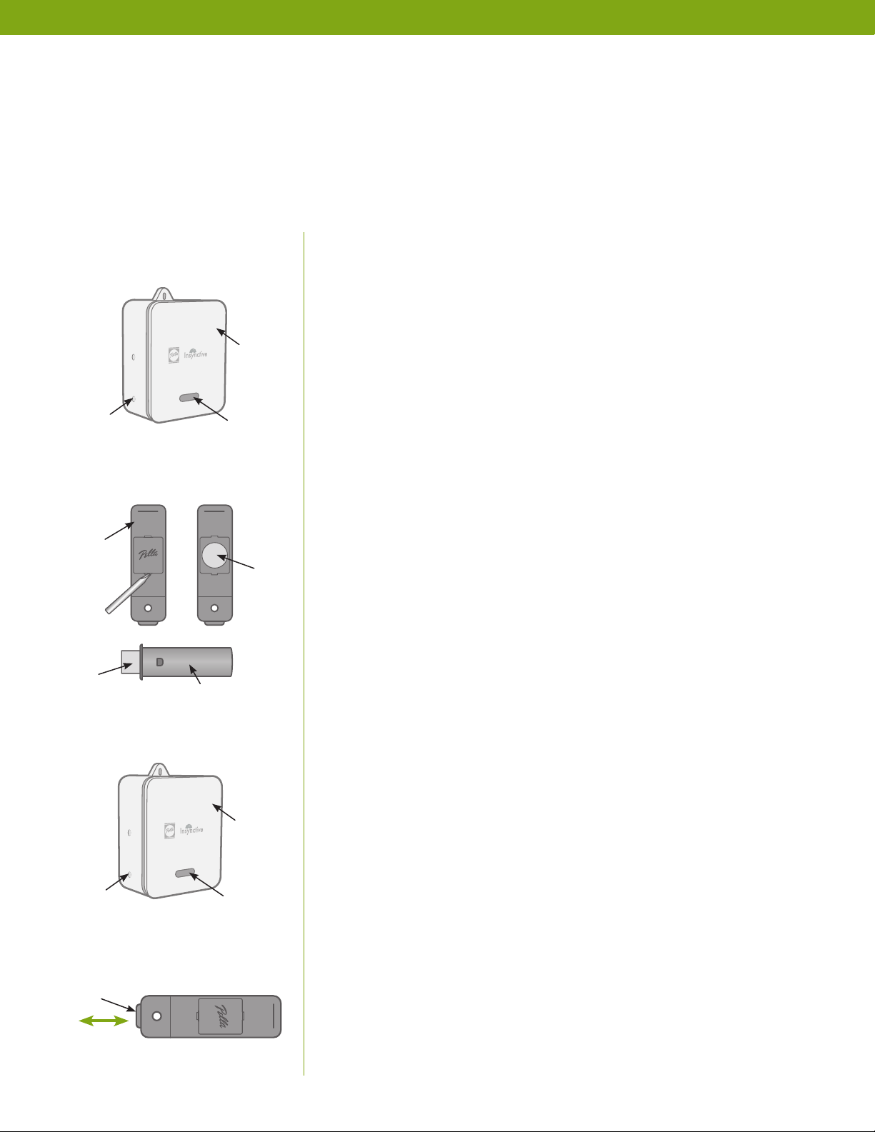
1. Get Started
Plug BRIDGE into an electrical outlet (light will turn green
and then flash blue).
NOTE: To set up BRIDGE, follow Bridge Quick Start Guide or
Bridge Product Guide, or visit Insynctive.Pella.com/Bridge for
more information.
2. Prepare LOCK SENSOR and OPEN/CLOSE SENSOR
Use flathead screwdriver as a lever to gently remove the
battery cover on LOCK SENSOR. Carefully remove
the battery with the flathead screwdriver and remove the
plastic tab separating the battery from LOCK SENSOR.
Ensure the battery is properly installed. Replace battery
cover on LOCK SENSOR.
SYNC
BUTTON
LOCK
SENSOR
BRIDGE
LIGHT
BAT TERY
PLASTIC
TAB
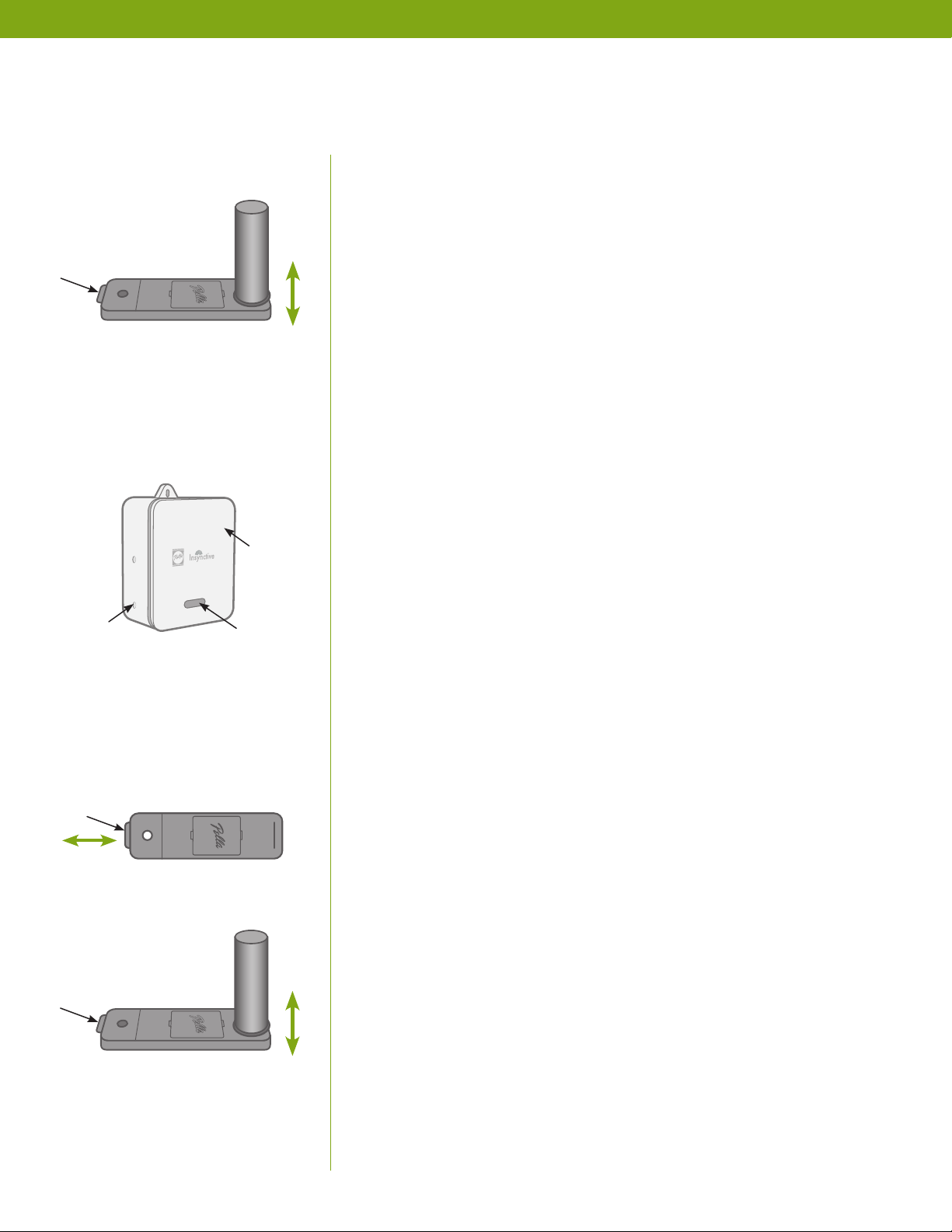
SYNC
BUTTON
PLUNGER
Depress plunger twice
within 2 seconds.
OPEN/CLOSE
SENSOR
LIGHT
Remove plastic tab from OPEN/CLOSE SENSOR. Install the
plastic endcap included in the package.
NOTE: Once the plastic tabs are removed from the batteries,
you will have 2 minutes to sync your LOCK SENSOR and
OPEN/CLOSE SENSOR to BRIDGE (Step 3). If 2 minutes pass
without a successful sync, remove and insert the battery again.
Battery covers must be installed to sync SENSORS.
3. Sync LOCK SENSOR and OPEN/CLOSE SENSOR to BRIDGE
Each SENSOR will need to be synced to your Insynctive™ system.
BRIDGE
To sync ENTRY DOOR DEADBOLT SENSORS with home
automation, follow instructions on page 6.
WITHOUT HOME AUTOMATION (STAND-ALONE MODE):
Press and hold BRIDGE Sync button until light begins flashing
orange. The Sync button is the bottom button (closer to the light
on the front) located on the side of BRIDGE.
BRIDGE is in sync mode while the orange light is flashing.
BRIDGE will remain in sync mode for 2 minutes. BRIDGE will
then beep and orange light will turn off to indicate BRIDGE
exited sync mode.
PELLA® INSYNCTIVE™ ENTRY DOOR DEADBOLT SENSOR PRODUCT GUIDE | 5
DETAILED INSTRUCTIONS (continued)
To sync LOCK SENSOR to BRIDGE, depress the plunger at the
bottom of LOCK SENSOR twice within 2 seconds.
If successfully synced, the light on BRIDGE will flash green and
beep once for 2 seconds.
PLUNGER
To sync OPEN/CLOSE SENSOR to BRIDGE, touch top (where you
removed battery tab) of the OPEN/CLOSE SENSOR to the magnet
Separate by at least 1 inch
twice within 2 seconds.
BRIDGE
at the top of LOCK SENSOR. (Top of LOCK SENSOR is the end
opposite the plunger. There is a line on LOCK SENSOR cover
above the battery door that locates the magnet.)
Separate LOCK SENSOR and OPEN/CLOSE SENSOR by at
least 1 inch. Repeat this step twice in 2 seconds.
If successfully synced, the light on BRIDGE will flash green and
beep once for 2 seconds.
If either SENSOR sync is unsuccessful, remove and reinstall
SENSOR battery to restart the 2-minute sync mode for SENSOR
and try again.
SYNC
BUTTON
PLUNGER
Depress plunger twice
within 2 seconds.
PLUNGER
LIGHT
Repeat the above steps until all your LOCK SENSORS and OPEN/
CLOSE SENSORS have been synced with BRIDGE. To exit sync
mode, press the Sync button on BRIDGE until the orange light
stops flashing.
WITH HOME AUTOMATION
Ensure BRIDGE is enrolled in Z-Wave network. See BRIDGE
Product Guide for process to sync to home automation system.
To sync LOCK SENSOR to BRIDGE, depress the plunger at the
bottom of LOCK SENSOR twice within 2 seconds. If successfully
synced, the light on BRIDGE will begin flashing blue. If either
SENSOR sync is unsuccessful, remove and reinstall SENSOR battery
to restart the 2-minute sync mode for SENSOR and try again.
To sync OPEN/CLOSE SENSOR to BRIDGE, touch top (where you
removed battery tab) of OPEN/CLOSE SENSOR to the magnet
at the top of LOCK SENSOR. (Top of LOCK SENSOR is the end
opposite the plunger. There is a line on LOCK SENSOR cover
above the battery door that locates the magnet.)
Separate by at least 1 inch
twice within 2 seconds.
Separate LOCK SENSOR and OPEN/CLOSE SENSOR by at least
1". Repeat this step twice in 2 seconds. If successfully synced,
the light on the BRIDGE will begin flashing blue. If either SENSOR
sync is unsuccessful, remove and reinstall SENSOR battery to restart
the 2-minute sync mode for SENSOR and try again.
PELLA® INSYNCTIVE™ ENTRY DOOR DEADBOLT SENSOR PRODUCT GUIDE | 6
 Loading...