

Page 1
© 2009 Pella Corporation
INSTALLATION INSTRUCTION -
INSTRUCCIONES DE INSTALACIÓN
FOR SQUARE DESIGN BAY AND BOW WINDOW
WITH SEAT BOARD
Lea las instrucciones en español en el reverso.
Read these instructions thoroughly before performing any steps.
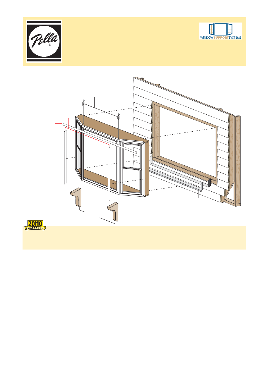
Cable clamps
Jamb covers
(2-1/2" Wide)
Head frame
expander
Part Number: 81470102
Flashing tape #1
Flashing tape #2
Knee braces
installing this product, you are acknowledging that this Limited Warranty is part of the terms of the
sale. Failure to comply with all Pella installation and maintenance instructions may void your Pella
product warranty. See Limited Warranty for complete details at http://warranty.pella.com.
Always read the Pella® Limited Warranty before purchasing or installing Pella products. By
Note: ese instructions may be used for Square Design Pella Bay and Bow windows that
have a head and seat board. Support cables are installed in factory assembled bay and bow
combinations.
Caution: e factory-installed support cables must be attached to members capable of
supporting 1,300 lbs. If the members are not capable of supporting 1,300 lbs., knee braces
must be used in addition to the cables. Bay and bow units are not intended to support any
roof structure. Consult an architect, engineer or construction professional if the ability of the
members to support the bay or bow is not known.
Installation Instructions for Typical Wood Frame Construction.
ese instructions were developed and tested for use with typical wood frame wall
construction in a wall system designed to manage water. ese instructions are not to be
used with any other construction method. Installation instructions for use with other
construction methods, multiple units or other bow and bay windows, may be obtained
from Pella Corporation, a local Pella retailer, or by visiting http://www.pella.com. Building
designs, construction methods, building materials, and site conditions unique to your project
may require an installation method dierent from these instructions and additional care.
Determining the appropriate installation method is the responsibility of you, your architect,
or construction professional.
Page 2
YOU WILL NEED TO SUPPLY: TOOLS REQUIRED:
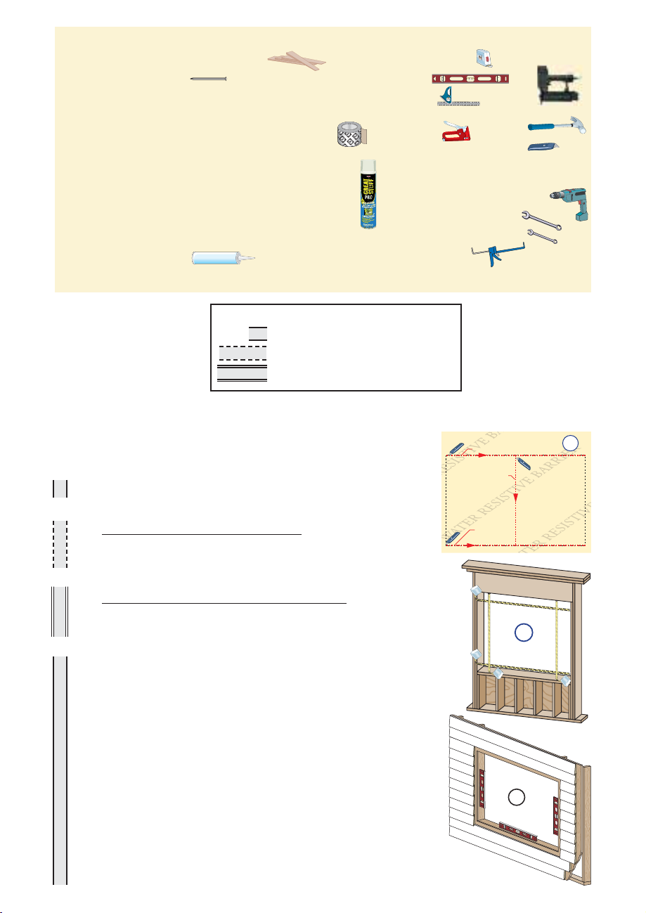
• Impervious Shims/Spacers (12 to 20)
• Finish nails, 1" brads
• 3/16" x 2-1/2" concrete screws (for masonry installation)
• Closed cell foam backer rod/sealant backer (12 to 30 ft.)
®
• Pella
SmartFlash™ foil backed butyl window and
door ashing tape or equivalent
• Great Stu
™
Window and Door Insulating Foam
Sealant by the Dow Chemical Company or equivalent
low pressure polyurethane window and door foam -
DO NOT use high pressure or latex foams.
• OSI Quad Multi-Polymer sealant or equivalent high
quality exterior grade polyurethane or silicone sealant.
4&"-"/5
(1 tube per window)
4&"-"/5
• Tape measure
• Level
• Square
• Hammer or Finish Nailer
• Stapler
• Scissors or utility knife
• Drill with a #2 Phillips (at least
4" long) and #3 square drive bit
(provided in cable clamp kit)
• 1/2" open end wrench
• 3/16" wrench or socket
• Sealant Gun
Installation will require two or more persons for safety reasons.
LEGEND STEPS REQUIRED OF:
ALL
= All applications
REPL APPS
NEW CONST
= Replacement applications
= New Construction applications
REMEMBER TO USE APPROPRIATE PERSONAL PROTECTIVE EQUIPMENT.
ROUGH OPENING PREPARATION
1
A. Remove all packaging from the window.
B. REPLACEMENT APPLICATIONS: Remove the
existing, window, trim, insulation and sealant from the
opening.
C. NEW CONSTRUCTION APPLICATIONS: Cut the
water resistive barrier. Fold the side aps into the opening
and staple to inside wall.
NEW CONST REPL APPS ALLALLALLALLALLALLALLALLALLALL
D. Conrm the window will t the opening. Measure all
four sides of the opening to make sure it is 3/4" larger
than the window in both width and height. Measure the
width and height in several places to ensure the header
and studs are not bowed.
Note: 1-1/2" or more of solid wood blocking is required
around the perimeter of the opening. Fix any problems
with the opening before proceeding. If installing new
blocking, install the blocking so it’s ush with the
exterior sheathing of the house. DO NOT attempt to
install a window in an under size opening.
Water Resistive Barrier
1st cut
3rd cut
2nd
cut
Interior
1D
1E
1C
E. Conrm the opening is plumb and level.
Note: It is critical the bottom is level.
Page 3
ROUGH OPENING PREPARATION (CONTINUED)
1
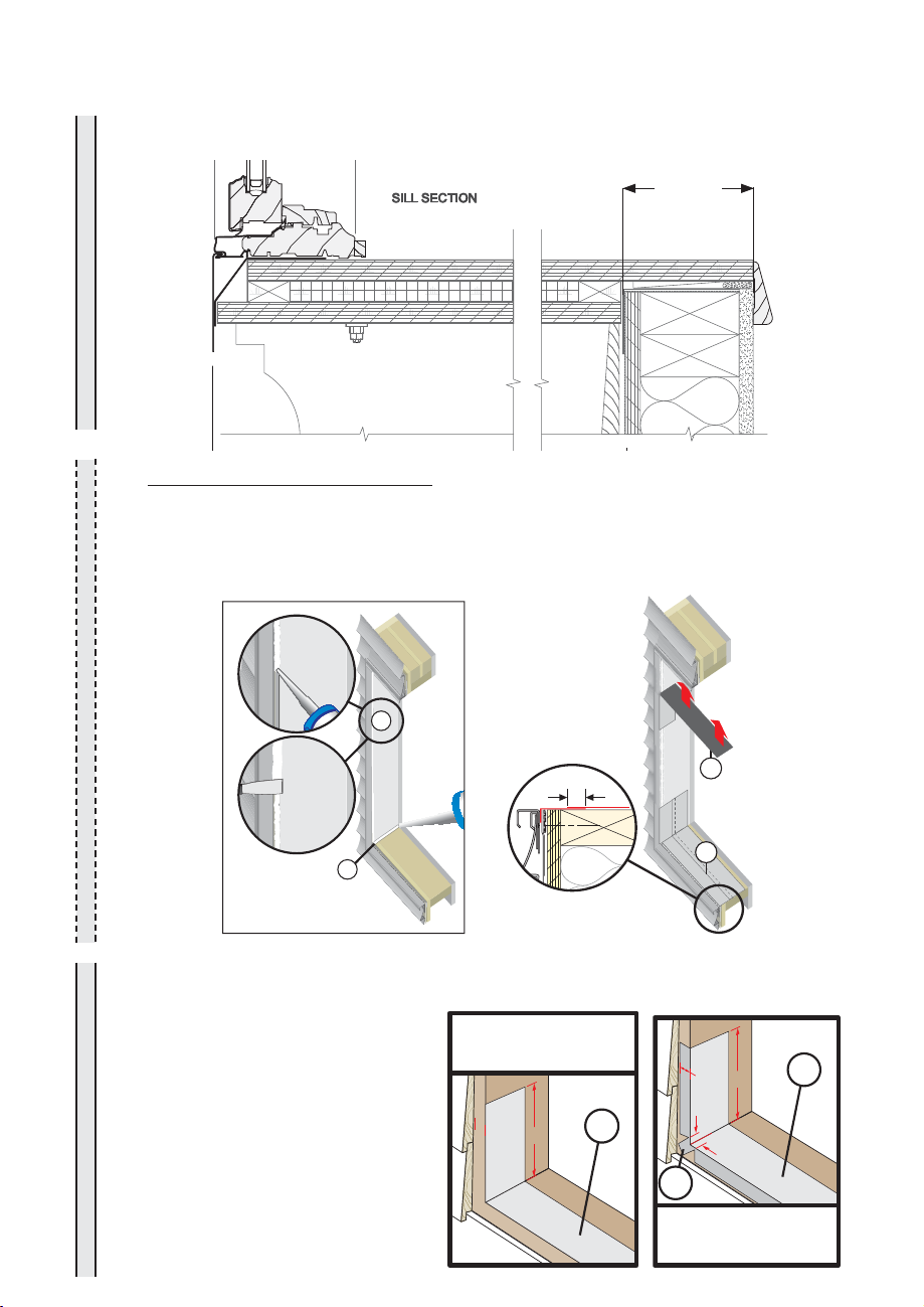
F. Conrm wall depth measurement. Measure bottom board cutback on unit to make sure it is
ALLALLALLALLALLALLALLALLALLREPL APPSREPL APPSREPL APPSREPL APPSREPL APPSREPL APPSALLALLALLALLALLALLALLALLALL
larger than the distance from the interior of wall to exterior of wall. If necessary, remove or cut
siding.
Measure
is
Distance
G. REPLACEMENT APPLICATIONS: Seal between exterior cladding and wall. If exterior
cladding is siding, apply sealant between the siding and rough opening at the head and jambs
and cover with ashing tape according to Express Replacement - No Siding Removal Opening
Preparation for Siding: Vinyl, Steel , Aluminum.’ If exterior cladding is brick, add blocking
at jamb to close the cavity between the brick and rough opening. Apply sealant at each joint
between the brick, blocking and rough opening and cover the joints with ashing tape.
HEAD
AND
JAMBS
ONLY
1G
PRESS
SEALANT
INTO
OPENING
1”
1G
1G
1G
H. Apply sill ashing tape #1. (Wood wall construction only). Cut a piece of ashing tape
12" longer than the opening. Apply at the bottom up to the exterior edge of the opening as
shown. If the sheathing or water barrier
is exposed, overlap 1" to the exterior as
shown in (1I).
Note: e tape is cut 12" longer than
Flashing tape
at the exterior edge
of the opening
1"
6"
the width so it will extend 6" up each
side of the opening.
6"
1H
1/2"
1/2"
I. Tab the sill ashing tape and fold (If
tape #1 overhangs 1" to the exterior).
Cut 1" wide tabs at each corner (1/2"
from each side of the corner) (1I). Fold
tape to the exterior and press rmly to
adhere it to the water resistive barrier.
1I
Flashing tape
overhanging 1"
to the exterior.
1H
Page 4
ROUGH OPENING PREPARATION (CONTINUED)
1
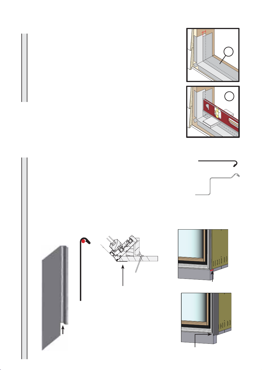
J. Apply sill ashing tape #2. Cut a piece of ashing tape 12"
ALLALLALLALLALLALLALLALLALLALLALLALLALLALLALLALLALLALLALLALLALLALLALLALLALLALLALL
longer than the opening width. Apply at the bottom, overlapping
tape #1 by at least 1". DO NOT allow the tape to extend past the
interior face of the opening.
Note: e ashing tape may not fully cover the
framing members.
K. Install and level sill spacers. Place 1" wide by 3/8" thick spacers
on the bottom of the opening 1" from each side and every 16"
on center. Add shims as necessary to ensure the spacers are level.
Once level, attach spacers and shims to prevent movement.
PREPARING AND SETTING THE WINDOW
2
If using Square Jamb Cover , Proceed to Step 2A.
If using Angle Jamb Cover , Proceed to Step 2B.
1"
1J
1K
Square Jamb Cover
Angle Jamb Cover
A. Install exterior jamb covers. Apply sealant along the leg of the jamb frame cover(s). Apply
a bead of sealant to the top corner of the bottom frame expander. Drive the short leg of the
jamb frame cover into the accessory groove using a block of wood with rounded edges and a
hammer. e notched end of the jamb cover goes toward the sill.
Square Jamb Cover
Sealant along leg of
Square Jamb Cover
Sealant Bead - Along Flange
Notched end of Square
Jamb Cover
Page 5
PREPARING AND SETTING THE WINDOW (CONTINUED)
2
TWO OR MORE PEOPLE WILL BE REQUIRED FOR THE FOLLOWING STEPS
ALLALLALLALLALLALLALLALLALLALLALLALLALLALLALLALLALLALLALLALLALLALLALLALLALLALLALLALLALLALL
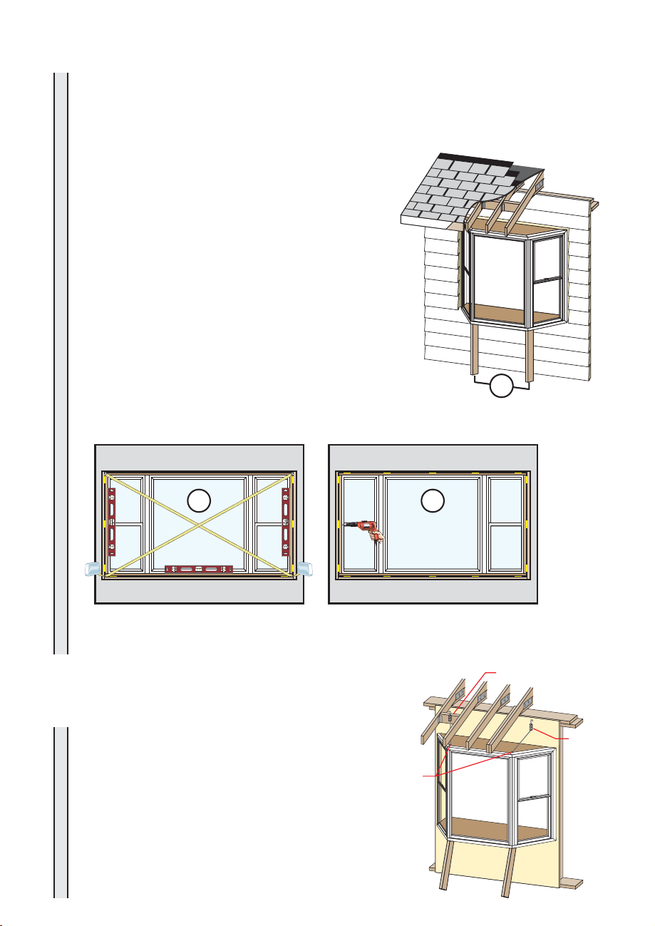
B. Insert the window from the exterior of the building. Place the seat of the window at the
bottom of the opening and slide the top into position. Center the window between the sides
of the opening to allow clearance for shimming.
Note: If cross bracing is required for sot
installation of the cable systems, proceed to Step 3A
and install cross bracing before unit is inserted into
the rough opening.
C. Place temporary bracing under the seat of the
window to raise the unit level.
D. Place a shim near the top of the one jamb board,
aligned with the top pre-drilled hole in the jamb
board. Drill a pilot hole and partially insert a #10 x 3"
at head screw provided. Repeat for the other jamb.
E. Continue placing shims at each pre-drilled
installation screw hole in the jamb boards to plumb
and square the window. Check window for squareness
by making sure diagonal measurement for corner to
corner is within 1/8" in both directions. Insert a #10
x 3" at head wood screw into each pre-drilled hole in
the jamb boards. Finish inserting the top screw in each
jamb board.
2C
Interior
2E
F. If desired, shim and fasten headboard to rough opening. To keep plywood straight, center
one nish head screw or 10D nish nail on units less than 10 feet wide and equally space two
fasteners on units wider than 10 feet.
CABLE CLAMP INSTALLATION
3
Note: Support cables are installed in factory
assembled bay and bow combinations.
Install Cable Clamps based on type of installation
needed. Cross Bracing Installation consists of
attaching 2 x 6 cross bracing between the rafter
tails. Header Mount Installation consists of
attaching to a solid structural member - header,
sill plates or wall stud.
Interior
2E
Cross bracing mount
T-nut
Header
mount
Page 6
CABLE CLAMP INSTALLATION (CONTINUED)
3
CROSS BRACING MOUNT OF CABLE CLAMPS
ALLALLALLALLALLALLALLALLALLALLALLALLALLALLALLALLALLALLALLALLALLALLALLALLALLALLALLALLALLALLALL
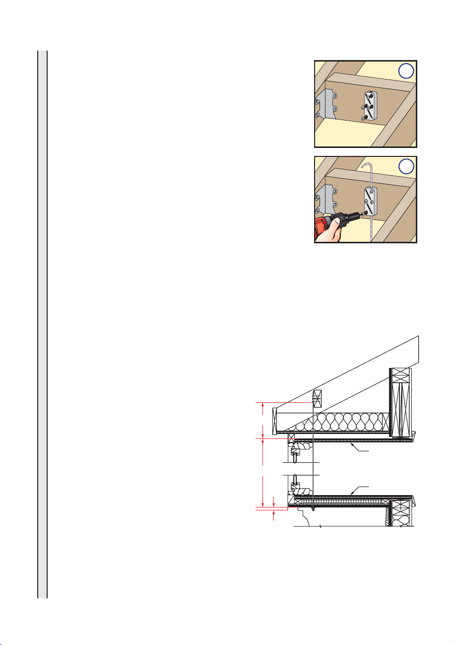
A. Install 2" x 6" cross braces between rafter tails, directly above
the cable holes in the bay/bow head board.
B. Install the cable clamps directly above the "T" nuts where
adequate support is available. Holding the clamp parallel to the
up-running cable, drive the #12 x 3-1/4" square drive screws
part way into the mounting surface using a #3 square drive bit.
3B
C. Run the cable up through the bottom of the cable clamp.
Hold the cable up tight above the clamp and drive the two
center clamp screws all the way in, locking the cable in place.
Drive the remaining #12 x 3-1/4" square screws all the way.
Note: Make sure all four screws are driven in at maximum
torque. Additional tensioning may be done with the nuts
on the opposite end of the cable at the bottom of the bay/
bow unit.
CROSS BRACING MOUNT - NON ACCESSIBLE CABLE ATTACHMENT
Note: Install the cable clamp and cable prior to installing the bay/bow unit.
A. Install 2 x 6 cross braces between the rafter
tails, directly above the cable holes in the bay/
bow head board.
B. Remove the cable from the bay/bow unit.
Measure the distance from the bottom of the
cable clamp to the bottom of the header plus
3/8" head clearance (A dimension). Measure
the height of the unit from the top of the
head board to the bottom of the seat board (B
dimension). Add "A" to "B" plus 1", to get the
correct length of cable hanging from the bottom
of the cable clamp. Insert the cable end through
the round hole of the cable clamp. Ensure the
correct length of cable is hanging below the
bottom of the cable clamp. Tighten the two
cable clamp corner screws. Insert one screw into
each of the center holes in the cable clamp, and
tighten to fully clamp the cable in position.
A
B
1"
3C
HEAD BOARD
SEAT BOARD
C. When the bay/bow unit is being installed, thread the threaded end of the cable through the
"T" nut, down the length of the bay/bow unit, and through the drilled hole in the seat board.
Place a washer and two hex nuts on each cable end.
Note: e interior mullion cover can easily be removed for this purpose and must be
reinstalled when installation is complete.
Page 7
CABLE CLAMP INSTALLATION (CONTINUED)
3
HEADER MOUNT OF CABLE CLAMPS
ALLALLALLALLALLALLALLALLALLALLALLALLALLALLALLALLALLALLALLALLALLALLALLALLALLALL
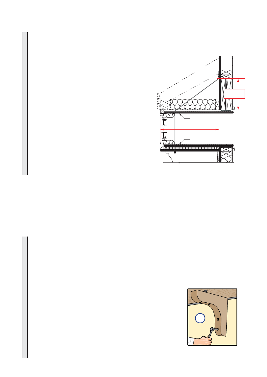
is method may only be used if the projection of the bay/bow is 18" or less.
Use the Cross Bracing method if the projection of the bay/bow is more than 18".
Note: Be sure that the cable clamps are secured
to a solid structural member - header, sill plates
or wall stud. If the structural member or cable
clamps are not securely attached, they may
loosen during or after installation causing the
bay/bow unit to sag.
A. Install the cable clamps. Drive the #12 x 3-1/4"
square screws part way into the mounting surface
using a #3 square drive bit.
B. Run the cable up through the bottom of the
cable clamp. Hold the cable up tight above the
clamp and drive the two center clamp screws all
the way in to lock the cable in place. Drive in the
remaining #12 x 3-1/4" square screws all the way.
Note: Make sure all 4 screws are driven in at
maximum torque. Additional tensioning may
be done with the nuts on the opposite end of the
cable at the bottom of the window.
SUPPORTING THE WINDOW
4
DASHED LINES INDICATE
POSSIBLE CONSTRUCTION
FOR GABLE ROOF
HEAD BOARD
18" PROJECTION
MAXIMUM
SEAT BOARD
MINIMUM
10-1/2”
A. Tighten the top hex nut on both cable ends. Using a 3/16" wrench or socket, hold the
cable end in position while tightening the top hex nut with a 1/2" wrench or socket. is
will keep the cable from twisting as the hex nuts are tightened.
B. Remove the temporary bracing. Check the window for level, plumb, sash reveal and
operation. Readjust, if needed.
Note: Be sure to use the temporary support when readjusting the hex nuts.
C. Remove blocking from under the seat board.
D. Tighten the locking (bottom) nut on both cable ends and
remove the temporary support once the nal position is found.
DO NOT cut the threaded end o the cable as this will prevent
future adjustment should it be needed.
E. Installation of knee braces is recommended to help support
the weight of the bay/bow unit. Weight calculations must take
into account the weight of the items that may be placed on
the seat board of the bay/bow unit. If the upper roof/framing
members are not capable of supporting 1,300 lbs. or if more
than 500 lbs. will be put on the seat board, knee braces must be
used in addition to the cables.
4E
Page 8
INSULATING FOAM APPLICATION
5
Caution: Ensure use of low pressure polyurethane window and door insulating foams
ALLALLALLALLALLALLALLALLALLALLALLALL
and strictly follow the foam manufacturer’s recommendations for application. Use of high
pressure foams or improper application of the foam may cause the window frame to bow and
hinder operation.
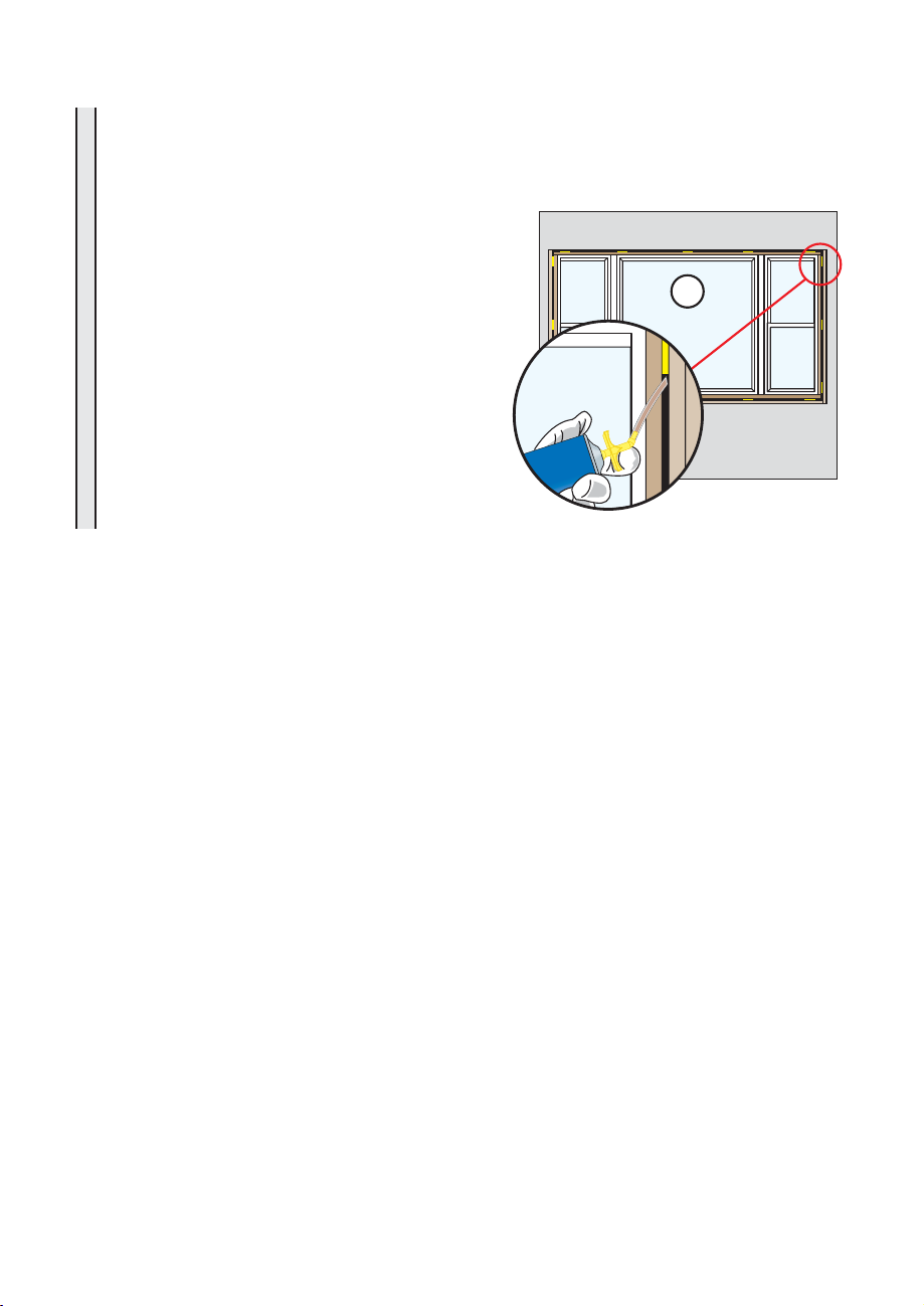
A. Apply insulating foam sealant. From the interior,
insert the nozzle of the applicator approximately 1"
deep into the space between the window and the
rough opening and apply a 1" deep bead of foam.
is will allow room for expansion of the foam and
will minimize squeeze out. If using foam other than
Great Stu
Sealant by the Dow Chemical Company, allow the
foam to cure completely (usually 8 to 24 hours)
before proceeding to the next step.
Note: It may be necessary to squeeze the end
of the tube with pliers to be able to insert into
the space between the jamb boards and the
rough opening, and between the head and seat
board and the rough opening.
™
Window and Door Insulating Foam
Interior
5A
Page 9
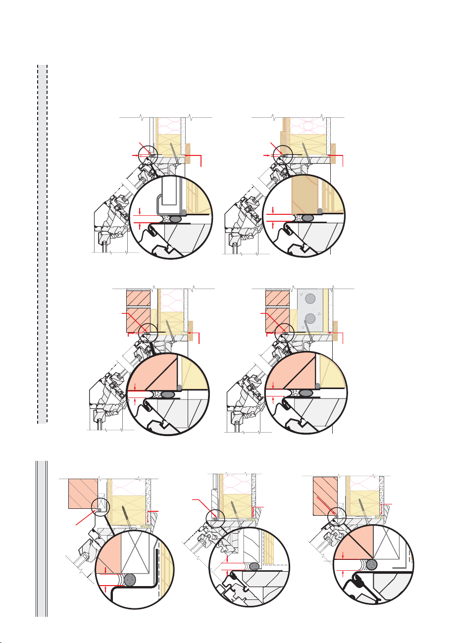
SEALING THE WINDOW TO THE
EXTERIOR WALL CLADDING
6
Note: e sealant details shown are standard recommendations from the sealant industry.
Contact your sealant supplier for recommendations and instructions for these and any other
applications.
REPL APPSREPL APPSREPL APPSREPL APPSREPL APPSREPL APPSREPL APPSREPL APPSREPL APPS
VINYL SIDING REPLACEMENT 2X4
WOOD SIDING REPLACEMENT 2X6
Backer Rod
Sealant typical
3/8" Clearance
Backer Rod
and
Sealant typical
3/8" Clearance
and
Insulating
Foam
3/8"
BRICK FRAMED REPLACEMENT
Insulating
Foam
3/8"
Backer Rod
and
Sealant typical
3/8" Clearance
3/8"
BRICK SMALL BLOCK REPLACEMENT
Air Gap
Backer Rod
and
Sealant typical
3/8" Clearance
3/8"
Block
Insulating
Foam
1 x 2
Sheet Rock / Lathe-Plaster
Insulating
Foam
JAMB - BRICK VENEER (Casement)
NEW CONSTNEW CONSTNEW CONSTNEW CONST
Backer Rod
and Sealant
typical
3/8"
Angle Jamb Cover Square Jamb Cover
Insulating
Foam
JAMB - 2X4 FRAME
Backer Rod
and
Sealant typical
3/8"
Sealant typical
Insulating
Foam
Backer Rod
and
JAMB - BRICK VENEER
3/8"
Insulating
Foam
Page 10
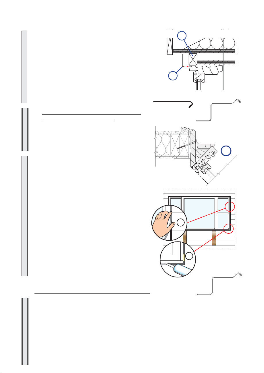
SEALING THE WINDOW TO THE
EXTERIOR WALL CLADDING (CONTINUED)
6
A. Install wood blocking between the top of the
ALLALLALLALLALLALLALL
window and the sot as shown. e blocking
should be ush with the exterior of the window
frame.
B. Apply a bead of sealant on the leg of the head
frame expander and install by tapping on it
using a block of wood with rounded edges and
a hammer. Frame expander is pre-notched and
bent from the factory.
6A
6B
If using Square Jamb Cover, Proceed to Step 6C.
If using Angle Jamb Cover, Proceed to Step 6G.
C. NEW CONSTRUCTION APPLICATIONS
WITH SQUARE JAMB COVER: Flash
from jambs to water resistive barrier. In new
NEW CONSTNEW CONSTNEW CONSTNEW CONST NEW CONST
construction application, use ashing tape to
ash from the jamb of the unit to the water
resistive barrier. Overlap onto the unit jamb
at least 3/8”. If necessary, repair any punctures
with another piece of ashing tape
D. Insert backer rod. If required, install siding,
ALLALLALLALLALLALLALLALLALLALLALLALL
then insert backer rod into the space between
the exterior nish material and unit exterior
deep enough to provide at least a 1/2" clearance
between the backer rod and the exterior face of
the wall sheathing.
Note: Backer rod adds shape and depth for the
sealant line.
E. Apply a bead of high quality exterior grade
sealant to the entire perimeter of the window,
except for one inch at either side of the sill. DO
NOT ll between the frame expander and the
under side of the seat board.
F. Shape, tool and clean excess sealant. When
nished the sealant should be the shape of an
hourglass.
Note: is method creates a more exible
sealant line capable of expanding and
contracting.
Installation Complete.
INSTALLATION USING ANGLE JAMB COVERS:
G. Cut jamb covers to length. Measure height of one anker unit not including
head & seatboard. Cut jamb covers to 4-9/16” taller than anker unit height.
H. Notch leg of jamb covers. On one jamb cover, notch the leg 3” from one end and 2” from the
other end. Mirror these notches on the other jamb cover, to create a right and left handed part.
I. Install exterior jamb covers. Apply sealant along the leg of each jamb cover and drive this leg
into the accessory groove using a block of wood with rounded edges and a hammer. Install the
jamb covers with the 3” notch towards the sill.
J. Nail the jamb covers to the wall using one nail on each end and one in the center.
K. Cut two pieces of ashing tape 6” longer than the jamb covers. Apply tape 3” above the top
of the jamb cover, overlapping it onto the water resistive barrier.
Square Jamb Cover
6D
Angle Jamb Cover
Angle Jamb Cover
Exterior
6E
6C
Page 11
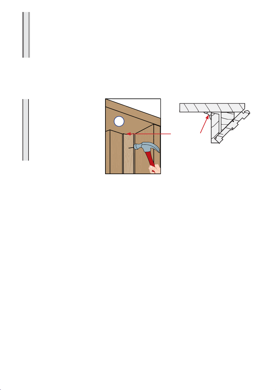
L. Insert backer rod and apply sealant. Install siding, and insert backer rod between the each
jamb cover and the exterior nish material as deep as it will go. Apply a bead of high quality
exterior sealant on top of the backer rod and a corner bead to the top of the head frame
expander. Shape, tool, clean excess sealant. When nished, the sealant should be the shape of
NEW CONSTNEW CONST
an hourglass.
Note: Backer rod adds shape and depth for the sealant line. is method creates a more
exible sealant line capable of expanding and contracting.
INSTALLING INTERIOR JAMB COVE MOULD
7
A. Install the interior
ALLALLALLALLALLALL
cove mould. Remove
cove mould from
accessory package
and dry t over the
installation screws.
Install interior cove
mould and secure
with 1" brads into the
jamb and trim.
7A
Cove Mould
Page 12
INTERIOR FINISHING
ALLALLALLALLALLALLALLALLALLALLALLALLALLALLALLALLALLALLALLALLALLALLALLALLALLALLALLALLALLALLALLALLALLALL
If products cannot be nished immediately, cover with clear plastic to protect from dirt, damage
and moisture. Remove any construction residue before nishing. Sand all wood surfaces lightly
with 180 grit or ner sandpaper. DO NOT use steel wool. BE CAREFUL NOT TO SCRATCH
THE GLASS. Remove sanding dust.
Pella products must be nished per the below instructions; failure to follow these instructions voids
the Limited Warranty.
• On casement and awnings, it is optional to paint, stain or nish the vertical and horizontal sash
edges.
• On single-hung and double-hung, do not paint, stain or nish the vertical sash edges, any nish
on the vertical sash edges may cause the sash to stick; it is optional to paint, stain or nish the
horizontal sash edges.
• On patio doors, it is optional to paint, stain or nish the vertical and horizontal panel edges.
Note: To maintain proper performance do not paint, nish or remove the weather-stripping,
mohair dust pads, gaskets or vinyl parts. Air and water leakage will result if these parts are
removed. After nishing, allow venting windows and doors to dry completely before closing
them.
Pella Corporation is not responsible for interior paint and stain nish imperfections for any
product that is not factory-applied by Pella Corporation. Use of inappropriate nishes, solvents,
brickwash, or cleaning chemicals will cause adverse reactions with window and door materials and
voids the
Limited Warranty.
For additional information on nishing see the Pella Owner's Manual or go to www.pella.com.
EXTERIOR FINISH
e exterior frame and sash are protected by aluminum cladding with our tough EnduraClad®
or EnduraClad Plus baked-on factory nish that needs no painting. Clean this surface with mild
soap and water. Stubborn stains and deposits may be removed with mineral spirits. DO NOT use
abrasives. DO NOT scrape or use tools that might damage the surface.
Use of inappropriate nishes, solvents, brickwash or cleaning chemicals will cause adverse reactions
with window and door materials and voids the Limited Warranty.
CARE AND MAINTENANCE
Care and maintenance information is available in the Pella Owner’s Manual. You can obtain an
owner’s manual by contacting your local Pella retailer. is information is also available on www.
pella.com.
IMPORTANT NOTICE
Because all construction must anticipate some water inltration, it is important that the wall
system be designed and constructed to properly manage moisture. Pella Corporation is not
responsible for claims or damages caused by anticipated and unanticipated water inltration;
deciencies in building design, construction and maintenance; failure to install Pella
accordance with Pella installation instructions; or the use of Pella products in wall systems which
do not allow for proper management of moisture within the wall systems. e determination of the
suitability of ashing and sealing systems are the responsibility of the Buyer or User, the architect,
contractor, installer, or other construction professional and are not the responsibility of Pella.
Pella products should not be used in barrier wall systems which do not allow for proper
management of moisture within the wall systems, such as barrier Exterior Insulation and Finish
Systems, (EIFS) (also known as synthetic stucco) or other non-water managed systems. Except
in the states of California, New Mexico, Arizona, Nevada, Utah, and Colorado, Pella makes no
warranty of any kind on and assumes no responsibility for Pella windows and doors installed in
barrier wall systems. In the states listed above, the installation of Pella Products in barrier wall or
similar systems must be in accordance with Pella’s installation instructions.
Product modications that are not approved by Pella Corporation will void the Limited Warranty.
®
products in
 Loading...