

Pella 81AK0101 User Manual

© 2011 Pella Corporation
INSTALLATION INSTRUCTION -
Part Number: 81AK0101
NAIL FIN INSTALLATION AFTER WEATHER BARRIER AND
FRAME SCREW OR CLIP INSTALLATION FOR REPLACEMENT
ALUMINUM-CLAD EXTERIOR HINGED PATIO DOORS (PELLA® PROLINE AND DESIGNER SERIES®)
ALUMINUM-CLAD EXTERIOR ENTRY DOORS (PELLA® AND ARCHITECT SERIES®)
Please read thoroughly and understand completely all the steps in this instruction prior to
beginning installation.
Installation with Nail Fin follow steps 1, 2, 3, 4, 6, 7
Replacement Installation Without Nail Fin
follow steps 1, 2, 3, 5, 6, 7
Important Safety Information:
These instructions were developed and tested for use with typical wood frame wall construction
in a wall system designed to manage water. These instructions are not to be used with any
other construction method. Installation instructions for use with other construction methods,
multiple units or bow and bay windows, may be obtained from Pella Corporation, a local Pella
retailer or by visiting http://www.pella.com. Building designs, construction methods, building
materials, and site conditions unique to your project may require an installation method
different from these instructions and additional care. Determining the appropriate installation
method is the responsibility of you, your architect or construction professional.
REMEMBER TO USE APPROPRIATE PERSONAL PROTECTIVE EQUIPMENT.
Always read the Pella® Limited Warranty before purchasing or installing Pella
products. By installing this product, you are acknowledging that this Limited
Warranty is part of the terms of the sale. Failure to comply with all Pella installation
and maintenance instructions may void your Pella product warranty. See Limited Warranty for
complete details at http://warranty.pella.com.
The performance of any building is dependent upon the design, installation, and workmanship
of the entire building system. Pella Corporation strongly recommends consulting an
experienced architect, contractor or structural engineer prior to installation of Pella products.
The individual (building owner, architect, contractor, installer and/or consumer) responsible
for the project must take into account local conditions, building codes, inherent component
limitations, the effects of aging and weathering on building components, and other design
issues relevant to each project.
The determination of the suitability of all building components for each project, as well as the
design and installation of flashing and sealing systems, are the responsibility of the building
owner, architect, contractor, installer and/or consumer.
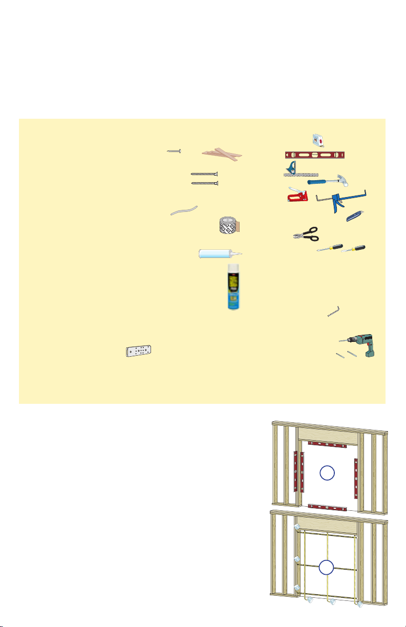
YOU WILL NEED TO SUPPLY: TOOLS REQUIRED:
• Composite or Impervious shims/spacers (12 to 20)
• 2" galvanized roofing nails (1/4 lb.)
• #10 x 3-1/2" corrosion resistant wood screws
(Performance Upgrade & HurricaneShield)
• Masonry screws for concrete applications
(Minimum of 3/16’ diameter x 3")
• Closed cell foam backer rod/sealant backer
(21 to 30 ft.)
• Pella® SmartFlash™ foil backed butyl window and
door flashing tape or equivalent
• High quality exterior grade polyurethane or silicone
sealant (2 to 3 tubes per door)
• Great Stuff™ Window and Door Insulating Foam
Sealant by the Dow Chemical Company or equivalent low pressure polyurethane window and door
foam - DO NOT use high pressure or latex foams
• Sill pan (optional)
• Pella aluminum sill support or wood blocking
• Interior trim and/or jamb extensions (15 to 40 ft.)
Installation Clip Option:
• 6" or 8" installation clips
• #6 x 5/8" corrosion resistant flat head wood screws
• #8 x 1-1/2" corrosion resistant screws or 3/16" x
1-1/2" masonry screws
SEALANT
SEALANT
• Tape measure
• Level
• Square
• Hammer
• Stapler
• Sealant Gun
• Scissors or utility knife
• Tin Snips
• Screwdrivers
(#2 Phillips with 8" shaft
and small flat blade)
• T20 Torx Wrench
(Architect Series® Entry Door and
Pella® Entry Door)
• 1/8" Allen wrench
(Designer Series®)
• Drill
• Drill Bits 13/64" and
1/8" and masonry bit for
concrete applications
ROUGH OPENING
PREPARATION:
1
A. Confirm the opening is plumb and level.
Note: It is critical that the bottom is level.
B. Confirm the door will fit the opening. Measure all
four sides of the opening to make sure it is 3/4"
larger than the door in width and 1/2" larger in
height. Measure the width at the top, bottom, and
center. Measure the height at the far left side, the far
right side, and in the center.
Note: 1-1/2" or more of solid wood blocking is
required around the perimeter of the opening.
Fix any problems with the rough opening before
proceeding.
FOR REPLACEMENT INSTALLATION WHERE NAIL FIN IS
NOT BEING USED, GO TO STEP 5.
Interior
1A
Interior
1B
1F
1"
1/2"
1/2"
6"
1E
1"
1G
1H
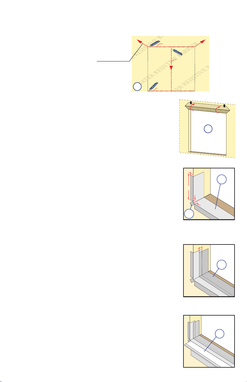
ROUGH OPENING PREPARATION (continued):
1
C. Cut the water resistive barrier.
4th cut:
Make a 6" cut up from
each top corner at a 45
angle to allow the water
resistive barrier to be lapped
over the fin at the head of
the door.
o
1C
Water Resistive Barrier
2nd cut
D. Fold the water resistive barrier. Fold side flaps into the
opening and staple to inside wall. Fold top flap up and
temporarily fasten with flashing tape.
FOR DOORS USING OPTIONAL SILL PAN GO TO STEP 1I.
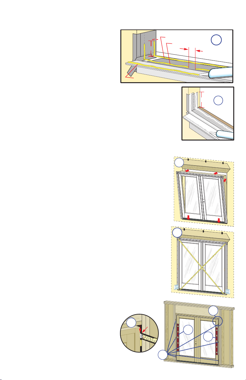
E. Apply sill flashing tape #1. Cut a piece of flashing tape 12"
longer than the opening width. Apply at the bottom of the
opening as shown (IE) so it overhangs 1" to the exterior.
Note: The tape is cut 12" longer than the width so that it will
extend 6" up each side of the opening.
F. Tab the sill flashing tape and fold. Cut 1" wide tabs at each
corner (1/2" from each side of the corner) (1F). Fold tape to
the exterior and press firmly to adhere it to the water resistive
barrier.
1st cut
3rd cut
Exterior
1D
G. Apply sill flashing tape #2. Cut a piece of flashing tape
12" longer than the opening width. Apply at the bottom,
overlapping tape #1 by at least 1". DO NOT allow the tape to
extend past the interior face of the framing (1G).
In-swing doors:
If the wall depth is greater than 5", add a third piece of
flashing tape. The flashing tape should come to within 1" of
the interior face of the framing.
Note: The flashing tape may not fully cover the framing
members.
H. Attach the aluminum sill support or wood blocking to the
exterior of the box plate to support the edge of the door sill.
Place the sill support flush with the subfloor.
GO TO STEP 2
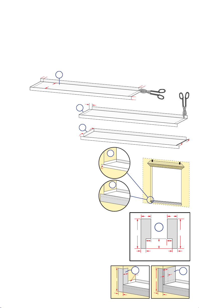
ROUGH OPENING PREPARATION (continued):
EXTERIOR SILL PAN LIP
Flashing Tape
1"
1-1/2"
1-1/2"
9"
1
Optional Sill Pan Instructions:
I. Cut the sill pan to the width of the rough opening plus 2".
Note: The 2" added onto the rough opening width is for a 1" bend on each end.
J. Make a 1" cut in each fold at both end of the sill pan.
Note: These cuts will allow the edges of the sill pan to be bent.
Note: 4-5/8" wide for Out-Swing and In-Swing for 4-9/16" wall condition. For other
wall conditions, measure wall depth and add 1/16".
1J
1"
Variable
K. Cut 1" off each end
of the interior sill
pan lip.
INTERIOR SILL PAN LIP
EXTERIOR SILL PAN LIP
1K
1"
INTERIOR SILL PAN LIP
EXTERIOR SILL PAN LIP
1L
L. Bend each end of the
sill pan upwards.
EXTERIOR SILL PAN LIP
1"
1"
INTERIOR SILL PAN LIP
M. Install the sill pan by sliding into
1M
place until the exterior sill pan lip is
flush with the exterior of the rough
opening.
N. Apply sill flashing tape. Cut a
piece of flashing tape 2" longer
EXTERIOR SILL PAN LIP
Install flush
against exterior
rough opening.
1N
than the opening width. Apply
at the bottom of the opening,
covering the exterior sill pan lip as
shown.
EXTERIOR SILL PAN LIP
Flashing Tape
Weather Barrier
Note: If applicable, apply spray
adhesive to building felt prior to
applying the flashing tape.
O. Cut two 9" pieces of flashing tape with a 1-1/2" x
3"tab at the bottom, on opposite corners as shown.
P. Apply the tabbed 9" pieces of flashing tap.
The tape is applied so 1-1/2" will cover the
inside of the rough opening and lap over the
side flange of the sill pan. The 1-1/2" x 3" tab
laps over the bottom flashing tape as shown.
Q. Cut two 6" pieces of flashing tape and
apply to each side of the rough opening,
overlapping the first piece by 1" and lapping
the bottom over the side flange of the sill pan
as shown.
1-1/2"
9"
EXTERIOR SILL PAN LIP
1-1/2"
9"
1P
Flashing Tape
1-1/2"
Tabs
Side
Flange
3"
1-1/2"
Exterior
1O
3"
1-1/2"
9"
EXTERIOR SILL PAN LIP
1-1/2"
3"
9"
1-1/2"
1-1/2"
Tabs
1"
Flashing Tape
9"
1Q
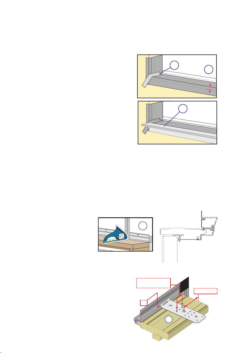
ROUGH OPENING PREPARATION (continued):
1
R. Cut a piece of flashing tape to the width of the opening. Install to the flanges of the sill
pan and overlap the tape from step 1N by 1". If needed add a second or third piece of
flashing tape until the sill pan is covered to the interior sill pan lip.
Note: The purpose of this tape is to seal the sill screws when installing the door.
S. Cut two pieces of flashing tape 1-1/2" x 6"
and apply to the bottom corners of the opening
by beginning in the corner of the sill pan, with
3/4" of the tape applied to the sill pan and
3/4" of the tape applied to the side flange. The
remainder of the tape is to be at a 45 degree
angle onto the exterior.
T. Attach the aluminum sill support or wood
blocking to the exterior of the box plate to
support the edge of the door sill. Place the sill
support flush with the subfloor.
1S
INTERIOR SILL PAN LIP
EXTERIOR SILL PAN LIP
1P
1T
INTERIOR SILL PAN LIP
EXTERIOR SILL PAN LIP
PREPARE THE DOOR
FOR INSTALLATION:
2
TWO OR MORE PEOPLE WILL BE REQUIRED TO HANDLE THE PANEL AND FRAME
SAFELY.
A. Remove plastic wrap and cardboard packaging from door. Do not remove plastic
shipping spacers. The shipping spacers will help keep the door square during
installation. Do not unlock or open the door until it is fully fastened.
Designer Series only: DO NOT cut the strap that goes from the lock holes to the sill of
the door.
Note: If grilles or hardware are removed from the door at this time, label them and
store them in a protected area.
1R
1"
B. For door without
EnduraClad® brickmould:
Fold out installation n to 90°.
Be careful not to remove or
tear the fin corners.
Note: If the fin corner is not
at 90°, the door will not align
correctly on the interior.
Note: The nail fin on doors with brickmould and nail
fin will come from the factory folded up.
C. Doors using Installation Clips: Install
installation clips. Place each clip so the lip
is facing up and against the installation fin
at the locations shown in the placement
diagram. Secure each clip by driving a #6 x
5/8" corrosion resistant screw through each
of the outer two holes of the three holes
shown.
Note: If clips are to be bent; pre-bend before
attaching to frame.
Note: Bending clips after attaching to frame
will bow the frame.
2B
#6 x 5/8” corrosion
resistant screws
Lip
Door with
Brickmould
6“ from end
2C
SETTING AND FASTENING THE DOOR:
3
A. Place three 3/8" beads of sealant.
1/2"
Place the first beads sealant 1/2" in
front of the base of the interior sill pan
lip. This bead should also continue up
6"
the corner of the sill pan at each end,
sealing the vertical joints of the sill
pan legs. Continue the first bead up
6" onto each jamb side of the rough
opening. The second bead should be
3rd Bead
approximately 1/2" from the exterior
edge of the rough opening, running from jamb to jamb with
a 2" break in the middle of the opening. Place a third sealant
bead in the groove of the sill support from end to end or 1/4"
from the exterior edge of the wood blocking.
TWO OR MORE PEOPLE WILL BE REQUIRED FOR THE
FOLLOWING STEPS:
B. Designer Series® Patio Doors: Cut and remove the strap
that runs from the door lock to the sill of the door.
C. For doors with no lock/bore: remove the screws and
blocking from the head and sill.
Caution: The door panels will swing freely
D. Insert the door from the exterior of the building. DO NOT
slide the bottom of the door into the opening. Sliding will
damage the sealant lines. Place the bottom of the door at
the bottom of the opening, then tilt the top into position.
Center the door between the sides of the opening to
allow clearance for shimming, and insert one roofing nail
in the first hole from the corner on each end of the top
nailing fin. These are used to hold the door in place while
shimming it plumb and square.
1st Bead
2nd Bead
INTERIOR SILL PAN LIP
EXTERIOR SILL PAN LIP
1
2
3
Applications
without sill pan
3D
3C
3E
3D
Exterior
3A
Leave a 2" break
in center of pan
6”
Exterior
3A
E. Plumb and square door. Place shims at each hinge and
lock strike location between the door and the sides of the
opening. Keep shims back 1/2" from the interior face of
the door frame. Insert shims in other locations as needed
starting up 6" from the bottom of the door to square it in
the opening. Check for frame twist; confirm consistent
weatherstrip compression around the perimeter of the
door. Make sure the panels are even across the bottom.
Note: On center latch double doors the lock strike will not
be shimmed since it is located in the
center of the unit. DO NOT over shim.
F. Check the interior reveal. Make sure
the measurement from the interior face
of the door to the interior face of the
wall is equal at several points around
the door.
3E
3F
1
INCHES
mm
2 0 3 0 4 0 5 0 6 0 7 0
2 3
Note: If the dimensions are not equal,
check to make sure the fins are folded
out to 90° at all points.
3D
3E
3D
3E
Interior
3D
3E
3E
3F
 Loading...