

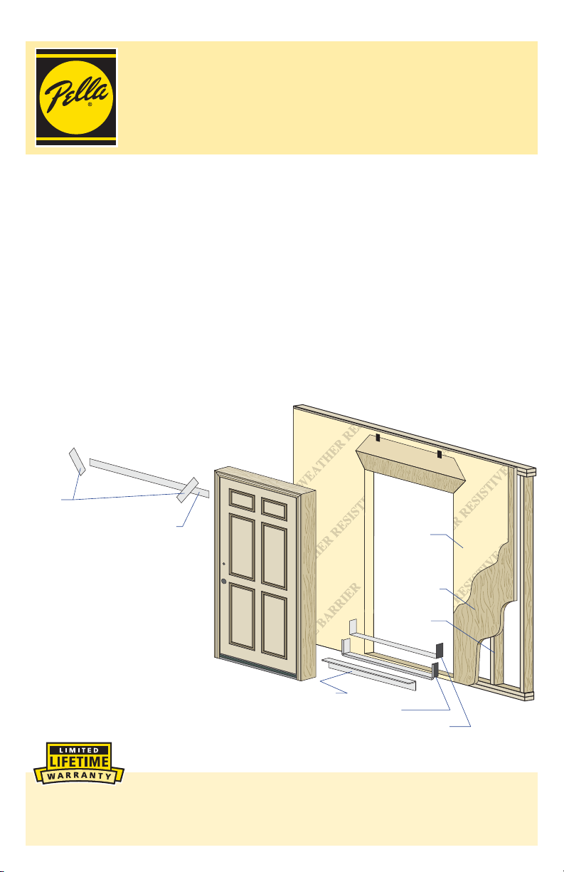
Pella 818T0101 User Manual
Part Number: 818T0101© 2011 Pella Corporation
INSTALLATION INSTRUCTION –
SINGLE PANEL, SINGLE PANEL WITH SIDELIGHT
COMBINATION AND 20 MINUTE FIRE RATED
WOOD FRAME ENTRY DOOR
Installation Instructions for Typical Wood Frame Construction.
These instructions were developed and tested for use with typical wood frame wall
construction in a wall system designed to manage water. These instructions are not
to be used with any other construction method. Installation instructions for use
with other construction methods may be obtained from Pella Corporation, a local
Pella retailer or by visiting http://www.pella.com. Building designs, construction
methods, building materials, and site conditions unique to your project may require an
installation method different from these instructions and additional care. Determining
the appropriate installation method is the responsibility of you, your architect, or
construction professional.
REMEMBER TO USE APPROPRIATE
PERSONAL PROTECTIVE EQUIPMENT.
Side
Flashing
Tape
installing Pella products. By installing this product, you are acknowledging that this
Limited Warranty is part of the terms of the sale. Failure to comply with all Pella
installation and maintenance instructions may void your Pella product warranty. See
Limited Warranty for complete details at http://warranty.pella.com.
To p
Flashing
Tape
Sill Support
Sill Flashing Tape #1
Sill Flashing Tape #2
Always read the Pella® Limited Warranty before purchasing or
Weather
Resistive
Barrier
Sheathing
Framing
YOU WILL NEED TO SUPPLY: TOOLS REQUIRED:
Ř Composite/impervious shims/spacers (12 to 20)
Ř #8 x 3" corrosion resistant woodscrews
Ř 16d galvanized finish nails or exterior grade
finish screws
Ř Pella foil backed butyl window and door flashing
tape or equivalent
Ř Closed cell foam backer rod/sealant backer
(17 to 21 ft.)
Ř Great Stuff™ Window and Door Insulating Foam
Sealant by the Dow Chemical Company or
equivalent low pressure polyurethane window
and door foam - DO NOT use high pressure or
latex foams.
Ř High quality exterior grade polyurethane sealant
(2 to 3 tubes per door)
Ř Pella aluminum sill support or 2 x 4 wood blocking
Ř Interior trim and/or jamb extensions (15 to 40 ft.)
Ř Aluminum head flashing
Ř Installation Clips (Optional)
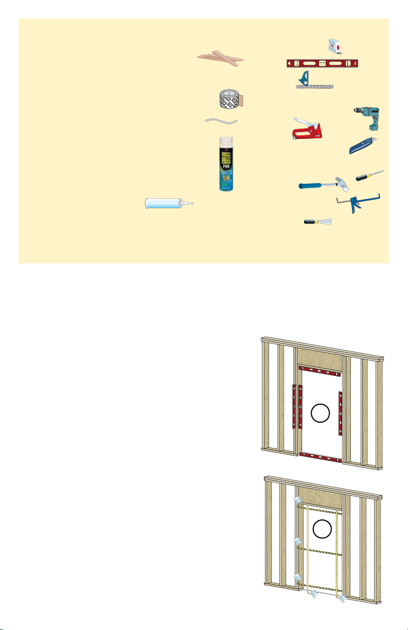
ROUGH OPENING PREPARATION
1
SEALANT
SEALANT
Ř Tape measure
Ř Level
Ř Square
Ř Drill with 1/8" and 3/16" drill bits
Ř Stapler
Ř Scissors or utility knife
Ř #2 & #3 Phillips screwdrivers
Ř Hammer
Ř Caulking gun
Ř Putty knife
A. Confirm the opening is plumb and level.
Note: It is critical the bottom is level.
B. Determine the finished floor height. If the
finished floor height will be more than 1"
higher than the surface the door will be set
on, add a filler board under the sill. The top
of the filler board should be within 1" of the
finished floor height.
C. Confirm the door will fit in the opening.
Measure all four sides of the opening to
make sure it is 3/4" larger than the door in
width and 1/2" larger in height. Measure the
opening width in several places to ensure
the studs are not bowed.
Note: 1-1/2" or more of solid wood
blocking (studs) is required around the
perimeter of the opening. Check the
wall for plumb and the opening for
square by checking opening diagonal
measurements. Fix any problems with the
rough opening before proceeding.
Interior
1A
1A
Interior
1C
1C
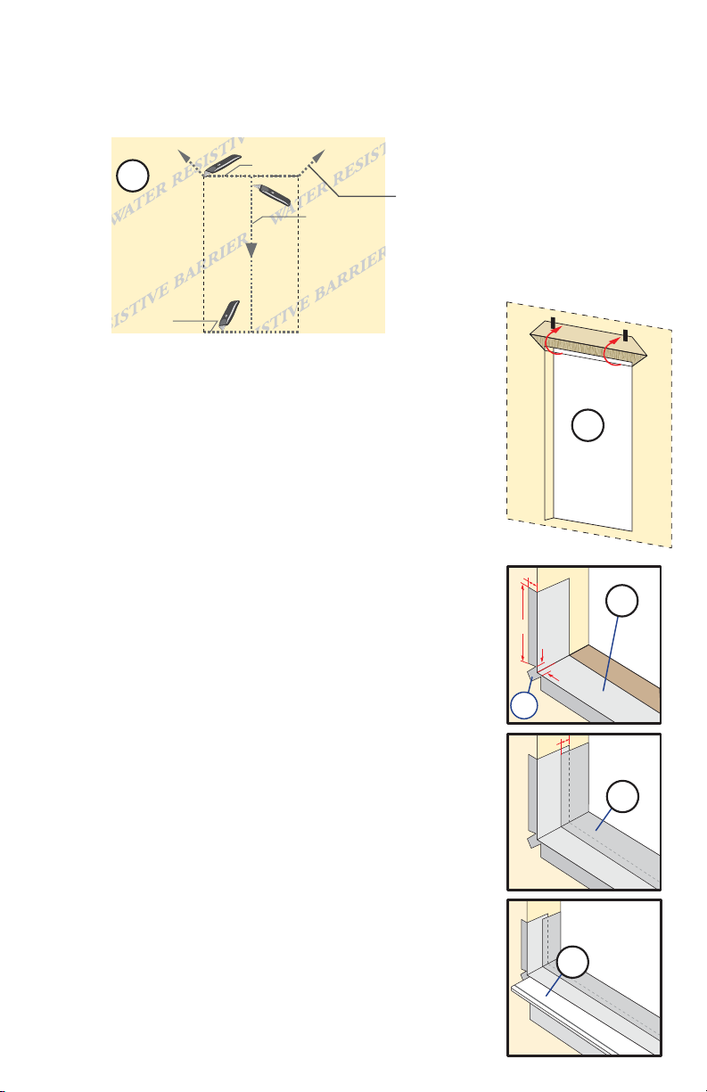
ROUGH OPENING PREPARATION
(CONTINUED)
1
D. Cut the weather resistive barrier, if applicable (1D).
Water Resistive Barrier
1D
1D
2nd cut
E. Fold the weather resistive barrier (1E). Fold side
flaps into the opening and staple to inside wall. Fold
top flap up and temporarily fasten with flashing tape.
F. Apply sill flashing tape #1. Cut a piece of
flashing tape 12" longer than the opening width.
Apply at the bottom of the opening as shown (1F)
so it overhangs 1" to the exterior.
Note: The tape is cut 12" longer than the width
so it will extend 6" up each side
of the opening.
G. Tab the sill flashing tape and fold. Cut 1" wide
tabs at each corner (1/2" from each side of corner)
(1G). Fold tape to the exterior and press firmly to
adhere it to the weather resistive barrier.
H. Apply sill flashing tape #2. Cut a piece of
flashing tape 12" longer than the opening width.
Apply at the bottom further towards the interior,
overlapping tape #1 by at least 1". Do not allow the
tape to extend past the interior face of the framing
(1H). If the wall depth is greater than 5", add a
third piece of flashing tape. The flashing tape
should come to within 1" of the interior face of the
framing.
Note: The flashing tape does not need to extend
all the way to the interior of the framing.
1st cut
3rd cut
4th cut:
Make a 6" cut up from
each top corner at a 45°
angle to allow the weather
barrier to be lapped over
the fin at the head of
the door.
1"
6"
1G
1G
1/2"
1"
1/2"
1E
1E
1F
1F
1H
1H
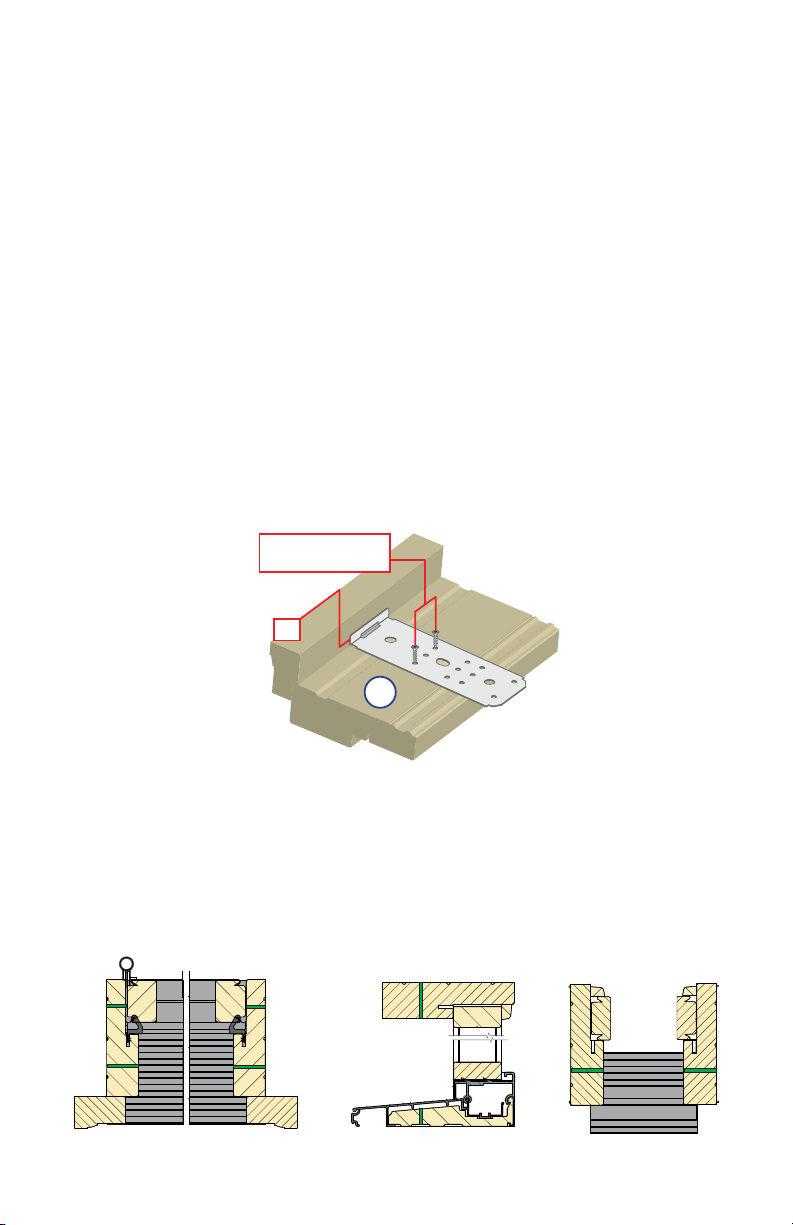
I. When required for adequate sill support,
attach the optional aluminum sill support or wood
blocking to the exterior of the box plate to support
the exterior edge of the door sill (1I). Place the sill
support flush with the sill rough opening.
1I
1I
2
PREPARE THE DOOR FOR INSTALLATION
TWO OR MORE PEOPLE WILL BE REQUIRED TO HANDLE
THE PANEL AND FRAME SAFELY.
A. Remove plastic wrap and cardboard packaging from door. DO NOT remove
plastic shipping spacers. The shipping spacers will help keep the door square
during installation. DO NOT open the door until it is fully fastened.
If Attaching with fasteners through the Brickmould go to Step 3
Anchoring Method – (Installation Clip or Frame Screw Through Frame)
B. Doors using Installation Clips: Install installation clips. Place each clip so
the lip is facing up and against the brickmould at the locations shown in the
placement diagram. Secure each clip by driving a #6 x 5/8" corrosion resistant
screw through each of the outer two holes of the three holes shown.
Note: If clips are to be bent; pre-bend before attaching to frame.
#6 x 5/8" corrosion
resistant screws
Lip
2B
C. Doors using Frame Screws: Open door panels; drill and counter-sink 3/16"
diameter clearance holes through the door frame jambs, (head and sill of
sidelight units) but not into the rough opening at the locations shown. Where
applicable, clearance holes are drilled though open hinge screw holes and
each strike hole.
Pilot Hole
Pilot Hole
Alternative Pilot Hole
for Screw Install
DOOR UNIT, JAMB TO JAMB
Pilot Hole
Alternative Pilot Hole
for Screw Install
Pilot Hole Pilot Hole
Pilot Hole
SIDELIGHT UNIT, HEAD TO SILL SIDELIGHT UNIT, JAMB TO JAMB
2
PREPARE THE DOOR FOR INSTALLATION
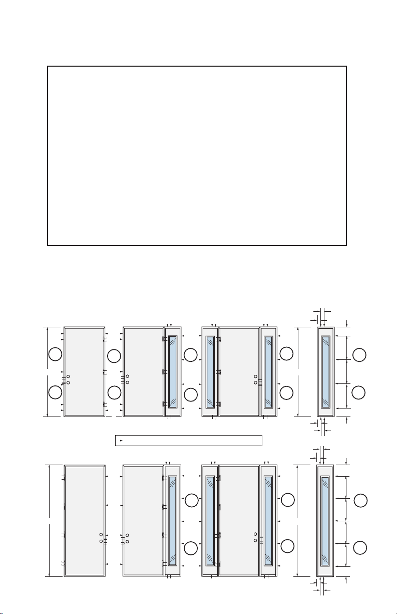
Anchor Spacing for Single Units:
Ř 2 – #10 x 2-1/2" screws at each hinge
Ř 2 – #10 x 2-1/2" screws at each strike
Ř #10 x 3" screw or clip directly across from each hinge
Ř #10 x 3" screw or clip 6" from each corner on 81-1/2" entry door frames only
(not sidelights) interacting with the rough opening
Ř #10 x 3" screw or clips as indicated on 97-1/2" entry door frames
Anchor Spacing for Combination Units:
Ř 2 – #10 x 3" screws at each sidelight head and sill
Ř #10 x 3" screw or clip at other indicated locations
Ř 2 - #10 x 2-1/2" screws at each hinge
Ř 2 - #10 x 2-1/2" screws at each strike
Diagrams for placement of installation clips or frame screw clearance
holes for 6'8" and 8' height doors and single doors with sidelights.
6"
2B
81-1/2"
6"
6"
2B
2B
2B
81-1/2"
3"
3"
9-1/4"
21"
2B
21"
97-1/2"
2C
2C
6"
6"
6"
= Screw or clip location other than at hinge or strike.
2C
2B
2C
2C
2B
2C
97-1/2"
3"
3"
3"
3"
3"
3"
21"
9-1/4"
6-3/4"
21"
21"
21"
21"
6-3/4"
2C
2B
2C
 Loading...