

Pella 818K0100 User Manual
Part Number: 818K0100©2011 Pella Corporation
INSTALLATION INSTRUCTION - INSTRUCCIONES DE INSTALACION
WOOD HINGED PATIO DOOR – (INCLUDES – STANDARD,
PERFORMANCE UPGRADE AND HURRICANESHEILD® IMPACT
RESISTANT IN-SWING, OUT-SWING)
Instrucciones enspañol en el reverso.
Important Safety Information:
Pella® HurricaneShield® Products have been tested in accordance with the large missile impact
testing requirements have been certifi ed to meet those requirements. Check with the individual
(building owner, architect, contractor, installer and/or consumer) responsible for the project in
addition to local building code offi cials to determine if these products comply with local codes.
Pella HurricaneShield Products are neither hurricane proof nor are they shatter proof. Severe wind
and rain may produce temporary conditions which exceed product performance standards. When
these units are subjected to intense storms or extreme conditions, which exceed the intended
design pressures, air, water and fl ying debris infi ltration may occur.
These instructions were developed and tested for use with typical wood frame wall construction
in a wall system designed to manage water. These instructions are not to be used with any
other construction method. Installation instructions for use with other construction methods,
multiple units or bow and bay windows, may be obtained from Pella Corporation or a local Pella
retailer, or by visiting http://www.pella.com. Building designs, construction methods, building
materials, and site conditions unique to your project may require an installation method different
from these instructions and additional care. Determining the appropriate installation method is the
responsibility of you, your architect, or construction professional.
IMPORTANT NOTICE: To achieve maximum door performance, the performance upgrade
installation may be required. Additional performance information may be obtained from your
Pella retailer of www.pella.com. All HurricaneShield doors are required to use the Performance
Upgrade Installation steps contained within this instruction.
REMEMBER TO USE APPROPRIATE PERSONAL PROTECTIVE EQUIPMENT.
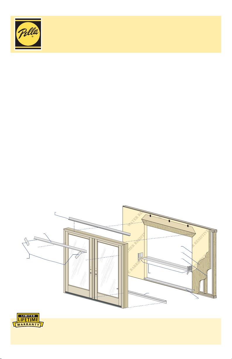
Aluminum Head Flashing
Top Flashing Tape
Water Resistive Barrier
Sheathing
Corner
Flashing
Tapes
Sill Support
Framing
Flashing Tape
Optional Sill Pan
Always read the Pella® Limited Warranty before purchasing or installing Pella
products. By installing this product, you are acknowledging that this Limited
Warranty is part of the terms of the sale. Failure to comply with all Pella installation and
maintenance instructions may void your Pella product warranty. See Limited Warranty for
complete details at http://warranty.pella.com.

The performance of any building is dependent upon the design, installation, and workmanship
of the entire building system. Pella Corporation strongly recommends consulting an
experienced architect, contractor, or structural engineer prior to installation of Pella products.
The individual (building owner, architect, contractor, installer and/or consumer) responsible
for the project must take into account local conditions, building codes, inherent component
limitations, the effects of aging and weathering on building components, and other design
issues relevant to each project.
The determination of the suitability of all building components for each project, as well as the
design and installation of fl ashing and sealing systems, are the responsibility of the building
owner, architect, contractor, installer and/or consumer.
YOU WILL NEED TO SUPPLY: TOOLS REQUIRED:
• Cedar or Impervious shims/spacers (12 to 20)
• 16d galvanized fi nish nails (1/4 lb.)
• #10 x 3-1/4" corrosion resistant wood screws
(Performance Upgrade and HurricaneShield)
• Masonry screws for concrete applications
(Minimum of 3/16" diameter x 3")
• Closed cell foam backer rod/sealant backer
(21 to 30 ft.)
®
• Pella
SmartFlash™ foil backed butyl window and door
fl ashing tape or equivalent
• High quality exterior grade polyurethane or silicone
SEALANT
sealant (2 to 3 tubes per door)
• Great Stuff
™
Window and Door Insulating Foam
SEALANT
Sealant by the Dow Chemical Company or equivalent
low pressure polyurethane window and door foam DO NOT use high pressure or latex foams
• Sill Pan (Optional)
6-5/8" x (Rough Opening Width + 2")
• Pella aluminum sill support or wood blocking
• Interior trim and/or jamb extensions (15 to 40 ft.)
• Aluminum Head Flashing
INSTALLATION CLIP OPTION:
• Tape measure
• Level
• Square
• Hammer
• Stapler
• Sealant gun
• Scissors or utility knife
• Tin snips
• Screwdrivers (#2 Phillips with
8" shaft and small fl at blade)
• T20 Torx Wrench
• Drill
• Drill bits 13/64" and 1/8"
and masonry bit for
concrete applications
• 6" or 8" installation clips
• #6 x 5/8" corrosion resistant fl at head wood screws
• #8 x 1-1/2" corrosion resistant screws or 3/16" x 1-1/2" masonry screw
1
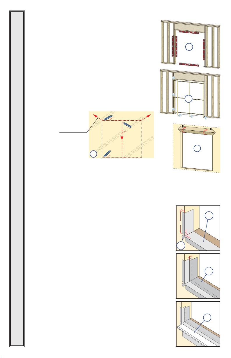
ROUGH OPENING PREPARATION
A. Confi rm the opening is plumb and level.
Note: It is critical that the bottom is level.
B. Confi rm the door will fi t the opening. Measure
all four sides of the opening to make sure it is 3/4"
larger than the door in width and 1/2" larger in height.
Measure the width at the top, bottom, and center.
Measure the height at the far left side, the far right
side, and in the center.
Note: 1-1/2" or more of solid wood blocking is
required around the perimeter of the opening.
Fix any problems with the rough opening before
proceeding.
C. Cut the water resistive barrier.
8BUFS3FTJTUJWF#BSSJFS
TUDVU
Interior
1A
Interior
1B
UIDVU
.BLFBDVUVQGSPN
FBDIUPQDPSOFSBUB
BOHMFUPBMMPXUIFXBUFS
SFTJTUJWFCBSSJFSUPCFMBQQFE
PWFSUIFmOBUUIFIFBEPG
UIFEPPS
P
$
SEDVU
OEDVU
D. Fold the water resistive barrier. Fold side fl aps into the
opening and staple to inside wall. Fold top fl ap up and
temporarily fasten with fl ashing tape.
For Doors Using Optional Sill Pan Go To Step 1I.
E. Apply sill fl ashing tape #1. Cut a piece of fl ashing tape 12"
longer than the opening width. Apply at the bottom of the
opening as shown (1E) so it overhangs 1" to the exterior.
Note: The tape is cut 12" longer than the width so that it
will extend 6" up each side of the opening.
F. Tab the sill fl ashing tape and fold. Cut 1" wide tabs at
each corner (1/2" from each side of corner) (1F). Fold tape
to the exterior and press fi rmly to adhere it to the water
resistive barrier.
G. Apply sill fl ashing tape #2. Cut a piece of fl ashing tape
12" longer than the opening width. Apply at the bottom,
overlapping tape #1 by at least 1". DO NOT allow the tape to
extend past the interior face of the framing (1G).
In-swing doors: If the wall depth is greater than 5", add a
third piece of fl ashing tape. The fl ashing tape should come to
within 1" of the interior face of the framing.
Note: The fl ashing tape may not fully cover the
framing members.
H. Attach the aluminum sill support or wood blocking to the
exterior of the box plate to support the edge of the door sill.
DOORS • ALL DOORS • ALL DOORS • ALL DOORS • ALL DOORS • ALL DOORS • ALL DOORS
Place the sill support fl ush with the subfl oor.
GO TO STEP 2
1"
6"
1F
1/2"
Exterior
1D
1E
1/2"
£
1H
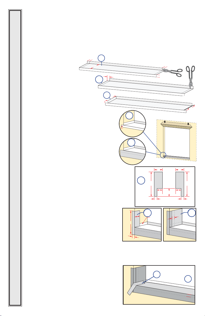
Optional Sill Pan Instructions.
I. Cut the sill pan to the width of the rough opening plus 2".
Note: The 2" added onto the rough opening width is for a 1" bend on each end.
J. Make a 1" cut in each fold at both ends of the sill pan.
Note: These cuts will allow the edges of the sill pan to be bent.
Note: 4-5/8" wide for Out-swing and In-swing for 4-9/16" wall condition. For
other wall conditions; measure wall depth and add 1/16".
1J
1"
1J
INTERIOR SILL PAN LIP
EXTERIOR SILL PAN LIP
1L
)
K. Cut 1" off each end of the
interior sill pan lip.
L. Bend each end of the center
Variable
(
1K
panel up.
M. Install the sill pan by sliding
into place until the exterior sill
pan lip is fl ush with the exterior
of the rough opening.
N. Apply sill fl ashing tape. Cut a piece
EXTERIOR SILL PAN LIP
of fl ashing tape 2" longer than the
opening width. Apply at the bottom of the
opening, covering the exterior sill pan lip
as shown.
Note: If applicable, apply spray
adhesive to building felt prior to
applying the fl ashing tape.
Weather Barrier
O. Cut two 9" pieces of fl ashing tape with a 1" x 3"
tab at the bottom, on opposite corners as shown.
P. Apply the tabbed 9" pieces of fl ashing tape.
The tape is applied so 2" will cover the inside of
the rough opening and lap over the side fl ange
of the sill pan. The 1" x 3" tab laps over the
bottom fl ashing tape as shown.
*/5&3*034*--1"/-*1
&95&3*034*--1"/-*1
&95&3*034*--1"/-*1
1M
1M
Install flush
against exterior
rough opening.
1N
1N
EXTERIOR SILL PAN LIP
Flashing Tape
1O
1O
*/5&3*034*--1"/-*1
9"
1" Tabs
1"
1"
Exterior
3"
2"
3"
3"
9"
2"
1" Tabs
Q. Cut two 6" pieces of fl ashing tape and
apply to each side of the rough opening,
overlapping the fi rst piece by 1" and
lapping the bottom over the side fl ange of
the sill pan as shown.
&95&3*034*--1"/-*1
'MBTIJOH5BQF
-
1P 1Q
4JEF
'MBOHF
R. Cut a piece of fl ashing tape to the width of the opening. Install to the fl anges of
the sill pan and overlap the tape from step 1N by 1”. If needed add a second or third
piece of fl ashing tape until the sill pan is covered to the interior sill pan lip.
Note: The purpose of this tape is to seal the sill screws when installing the door.
S. Cut two pieces of fl ashing tape 1-1/2" x
6" and apply to the bottom corners of the
opening by beginning in the corner of the sill
DOORS • ALL DOORS • ALL DOORS • ALL DOORS • ALL DOORS • ALL DOORS • ALL DOORS
pan, with 3/4" of the tape applied to the sill
pan and 3/4" of the tape applied to the side
fl ange. The remainder of the tape is to be at a
1S
INTERIOR SILL PAN LIP
EXTERIOR SILL PAN LIP
45 degree angle onto the exterior.
.
&95&3*034*--1"/-*1
'MBTIJOH5BQF
1R
1"
T. Attach the aluminum sill support or wood
blocking to the exterior of the box plate to
support the edge of the door sill. Place the
sill support fl ush with the subfl oor.
PREPARE THE DOOR FOR INSTALLATION
2
ALL DOORS
INTERIOR SILL PAN LIP
EXTERIOR SILL PAN LIP
TWO OR MORE PEOPLE WILL BE REQUIRED TO HANDLE THE PANEL AND
FRAME SAFELY.
A. Remove plastic wrap and cardboard packaging from door. Do not remove
plastic shipping spacers. The shipping spacers will help keep the door square
during installation. Do not unlock or open the door until it is fully fastened.
Note: If grilles or hardware are removed from the door at this time, label them
and store them in a protected area.
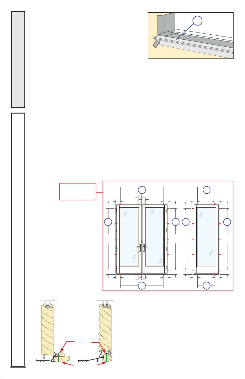
Standard Brickmould Installation go to Step 3
Applications for Performance Upgrade and HurricaneShield product requires
additional clip installation or screw installation. Clip installation prep is included in
Step 2B. Screw installation steps are included in Step 5.
For HurricaneShield and Performance
Upgrade Applications:
6"
DOUBLE OPERABLE
16" MAX
O.C.
2B
6"
6"
16" MAX
6"
O.C.
6"
6"
DIAGRAM FOR
PLACEMENT OF
FRAME SCREWS OR
INSTALLATION CLIPS
6"
1P
1T
SINGLE FIXED OR OPERABLE
2B
16" MAX
6"
6"
O.C.
6"
Out-Swing Sill
Out-Swing Sill In-Swing Sill
PERFORMANCE UPGRADE & HURRICANESHIELD DOORS
Screw
Location
Clearance Holes
2B
16"
MAX.
O.C.
6"
In-Swing Sill
16" MAX
6" 6"
O.C.
16" MAX
6"
6"
O.C.
5E
2B
16"
MAX.
O.C.
2B
16"
MAX.
O.C.
6"
6"
16" MAX
6" 6"
O.C.
2B
16"
MAX.
O.C.
6"
5E
 Loading...