

Pella 80AT0102 User Manual

Cable clamp
Jamb extensions
Cross bracing
Rafter tail
Jamb covers
Flashing tape
Knee braces
Bottom frame
expander
Head frame
expander
©2008 Pella Corporation
C.
,
INSTALLATION INSTRUCTION
INSTRUCCIONES DE INSTALACION
FOR BAY AND BOW WINDOW WITH SEAT BOARD
VENTANAS DE MIRADOR CON TABLA DE ASIENTO
Lea las instrucciones en español en el reverso.
Part Number: 80AT0102
By installing this product, you are acknowledging that this Limited Warranty is part of the terms of
Always read the Pella® Limited Warranty before purchasing or installing Pella products.
the sale. Failure to comply with all Pella installation and maintenance instructions may void your Pella
product warranty. See Limited Warranty for complete details at http://warranty.pella.com.
Note: These instructions may be used for all Pella Bay and Bow windows that have a
head and seat board. Support cables are installed in factory assembled bay and bow
combinations.
Caution: e factory-installed support cables must be attached to members capable of
supporting 1,300 lbs. If the members are not capable of supporting 1,300 lbs., knee braces
must be used in addition to the cables. Bay and bow units are not intended to support any
roof structure. Consult an architect, engineer or construction professional if the ability of the
members to support the bay or bow is not known.
Installation Instructions for Typical Wood Frame Construction.
These instructions were developed and tested for use with typical wood frame wall construction
in a wall system designed to manage water. ese instructions are not to be used with any
other construction method. Installation instructions for use with other construction methods,
multiple units or bow and bay windows, may be obtained from Pella Corporation, a local Pella
retailer, or by visiting http://www.pella.com. Building designs, construction methods, building
materials, and site conditions unique to your project may require an installation method
different from these instructions and additional care. Determining the appropriate installation
method is the responsibility of you, your architect, or construction professional.
Interior
1A
Interior
1B
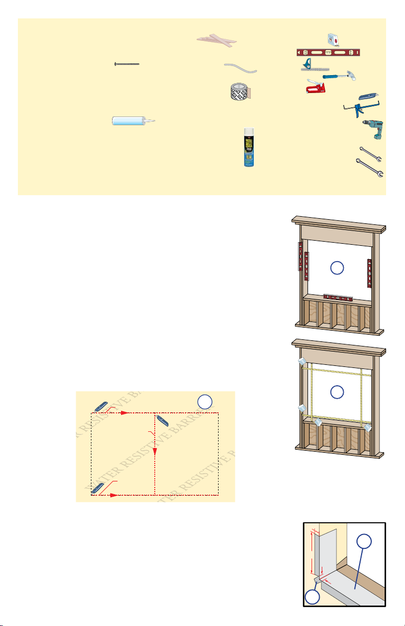
YOU WILL NEED TO SUPPLY: TOOLS REQUIRED:
SEALANT
SEALANT
1st cut
2nd
cut
3rd cut
Water Resistive Barrier
1C
1E
1"
1/2"
1/2"
6"
1D
• Cedar or Impervious shims/spacers (12 to 20)
• 10d galvanized nish nails or #8 x 2 1/2" at head corrosionresistant screws (4 to 6)
• Closed cell foam backer rod/sealant backer (20 to 35 ft.)
®
• Pella
SmartFlash™ foil backed butyl window and door
flashing tape or equivalent
• High quality exterior grade polyurethane or silicone sealant
(1 tube per window)
• Great Stuff
™
Window and Door Insulating Foam Sealant
by the Dow Chemical Company or equivalent low pressure
polyurethane window and door foam - DO NOT use high
• Tape measure
• Level
• Square
• Hammer
• Stapler
• Scissors or utility knife
• Sealant gun
• Drill with a #2 Phillips
and a #3 square drive bit
• 3/16" wrench or socket
• 1/2" open end wrench
pressure or latex foams
• Interior trim and/or jamb extensions (25 to 40 ft.)
• Knee braces (2)
REMEMBER TO USE APPROPRIATE PERSONAL PROTECTIVE EQUIPMENT.
ROUGH OPENING PREPARATION
1
A. Verify the opening is plumb and level.
Note: It is critical that the bottom is level.
B. Verify the window will fit the opening. Measure all four sides
of the opening to make sure it is 3/4" larger than the window
in both width and height. On larger openings measure the
width and height in several places to ensure the header or studs
are not bowed.
Note: 1-1/2" or more of solid wood blocking is required
around the perimeter of the opening. Fix any problems with
the rough opening before proceeding.
C. Cut the water resistive barrier. Fold side flaps into the
opening and staple to inside wall.
D. Apply sill flashing tape #1. Cut a piece of ashing tape 12" longer
than the opening width. Apply at the bottom of the opening as
shown (1D) so it overhangs 1" to the exterior.
Note: e tape is cut 12" longer than the width so that it will
extend 6" up each side of the opening.
E. Tab the sill flashing tape and fold. Cut 1" wide tabs at each
corner (1/2" from each side of corner) (1E). Fold tape to the
exterior and press rmly to adhere it to the water resistive barrier.
1"
1F
2B
Interior
2C
Interior
2F
2D
1G
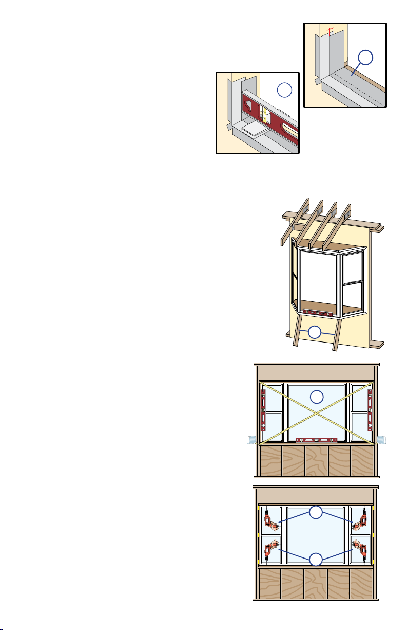
F. Apply sill flashing tape #2. Cut a piece of ashing tape 12" longer
than the opening width. Apply at the bottom, overlapping tape #1 by
at least 1". DO NOT allow the tape to extend past the interior face
of the framing (1F).
Note: e flashing tape may not fully cover the framing members.
G. Install and level sill spacers. Place 1" wide
by 3/8" thick spacers on the bottom of the
opening 1/2" from each side. Add shims
to ensure the spacers are level. Once level,
attach spacers and shims to the opening to
prevent movement.
SETTING THE WINDOW
2
TWO OR MORE PEOPLE WILL BE REQUIRED FOR THE FOLLOWING STEPS.
Note: In some installations, the cable clamps will not be
accessible for cable attachment and adjustment after the
window is installed. For this type of installation proceed to
Cross Bracing Mount - Non Accessible Cable Attachment. e
cable and clamp will have to be measured and installed before
the window is installed.
A. Insert the window from the exterior of the building. Place
the seat of the window at the bottom of the opening and slide
the top into position. Center the window between the sides of
the opening to allow clearance for shimming.
B. Place temporary bracing under the seat of the
window and raise the unit until level as shown (2B).
C. Plumb and square window. Place shims 1" from the
bottom and top of the window between the window and
the sides of the opening. Adjust the shims as required
to plumb and square the window in the opening. Place
shims at the midpoint of the window sides.
D. Nail one 10d finishing nail or drive a #8 x 2-1/2"
long screw on each end, through the seat board into
the rough opening.
E. Continue placing shims/spacers between the seat
board and the rough opening at not more than 16"
on center. Ensure the seat board is flat.
F. Nail one 10d finishing nail or drive a #8 x 2-1/2"
long screw on each end, through the head board into
the rough opening.
G. Place shims between the head board and the rough
opening at not more than 16" on center. Ensure the
head board is straight and level.

Cross bracing mount
Header
mount
T-nut
3B
3C
CABLE CLAMP INSTALLATION
HEAD BOARD
SEAT BOARD
1"
A
B
3
Note: Support cables are installed in factory assembled
bay and bow combinations.
Install Cable Clamps based on type of installation needed.
Cross Bracing Installation consists of attaching 2 x 6
cross bracing between the rafter tails. Header Mount
Installation consists of attaching to a solid structural
member - header, sill plates or wall stud.
CROSS BRACING MOUNT OF CABLE CLAMPS
A. Install 2 x 6 cross braces between the rafter tails, directly
above the cable holes in the bay/bow head board.
B. Install the cable clamps directly above the T-nuts where
adequate support is available. Holding the clamp parallel to the
up-running cable, drive the #12 x 3-1/4" square screws partway
into the mounting surface using a #3 square drive bit.
C. Run the cable up through the bottom of the cable clamp.
Hold the cable up tight above the clamp and drive the two
center clamp screws all the way in to lock the cable in place.
Drive in the remaining #12 x 3-1/4" square screws all the way.
Note: Make sure all 4 screws are driven in at maximum
torque. Additional tensioning may be done with the nuts
on the opposite end of the cable at the bottom of the bay/
bow unit.
CROSS BRACING MOUNT - NON ACCESSIBLE CABLE ATTACHMENT
Note: Install the cable clamp and cable prior to installing the bay/bow unit.
A. Install 2 x 6 cross braces between the rafter tails, directly
above the cable holes in the bay/bow head board.
B. Remove the cable from the bay/bow unit.
Measure the distance from the bottom of
the cable clamp to the bottom of the header
plus 3/8" head clearance (A dimension).
Measure the height of the unit from the top
of the head board to the bottom of the seat
board (B dimension). Add "A" to "B" to get
the correct length of cable hanging from the
bottom of the cable clamp. Insert the cable
end through the round hole of the cable
clamp. Ensure the correct length of cable
is hanging below the bottom of the cable
clamp. Tighten the two cable clamp corner
screws. Insert one screw into each of the
center holes in the cable clamp, and tighten
to fully clamp the cable in position.
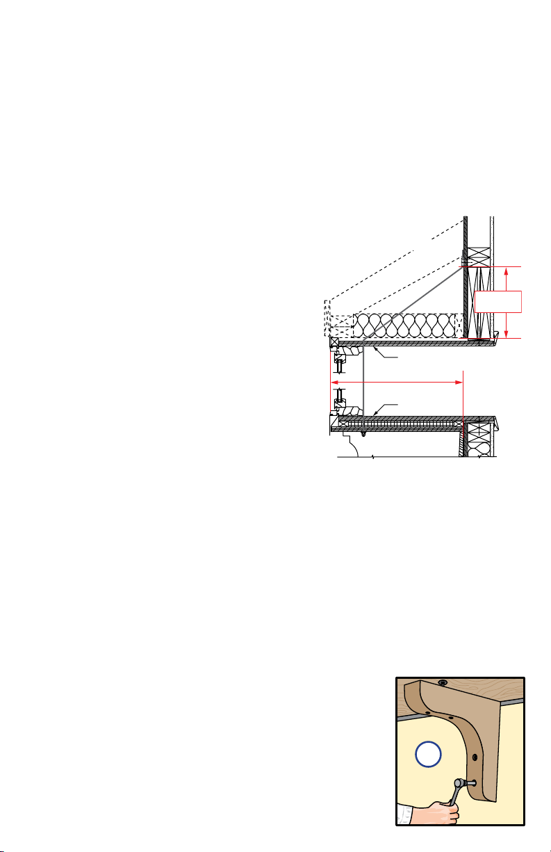
HEAD BOARD
SEAT BOARD
18" PROJECTION
MAXIMUM
DASHED LINES INDICATE
POSSIBLE CONSTRUCTION
FOR GABLE ROOF
MINIMUM
10-1/2”
4E
CABLE CLAMP INSTALLATION (continued)
3
C. When the bay/bow unit is being installed, thread the threaded end of the cable through
the "T" nut, down the length of the bay/bow unit, and out the drilled hole in the seat
board. Place a washer and two hex nuts on each cable end.
Note: e interior mullion cover can easily be removed for this purpose and must be
reinstalled when installation is complete.
HEADER MOUNT OF CABLE CLAMPS
is method may only be used if the projection of the bay/bow is 18" or less.
Use the Cross Bracing method if the projection of the bay/bow is more than 18".
Note: Be sure that the cable clamps are secured to a
solid structural member - header, sill plates or wall
stud. If the structural member or cable clamps are
not securely attached, they may loosen during or
after installation causing the bay/bow unit to sag.
A. Install the cable clamps. Drive the #12 x 3-1/4"
square screws part way into the mounting surface
using a #3 square drive bit.
B. Run the cable up through the bottom of the cable
clamp. Hold the cable up tight above the clamp and
drive the two center clamp screws all the way in to
lock the cable in place. Drive in the remaining #12
x 3-1/4" square screws all the way.
Note: Make sure all 4 screws are driven in at
maximum torque. Additional tensioning may be
done with the nuts on the opposite end of the cable
at the bottom of the window.
FASTENING THE WINDOW
4
A. Tighten the top hex nut on both cable ends. Using a 3/16" wrench or socket, hold the
cable end in position while tightening the top hex nut with a 1/2" wrench or socket. This
will keep the cable from twisting as the hex nuts are tightened with a wrench.
B. Secure the seat board and head board by using 10d nishing nails or 2-1/2" long
screws on 16" centers; nail or screw through the head board, seat board and shims
into the rough opening.
C. Remove the temporary bracing. Check the window for level, plumb, sash reveal
and operation. Readjust, if needed.
Note: Be sure to use the temporary support when readjusting
the nuts.
D. Tighten the locking (bottom) nut on both cable ends and
remove the temporary support once the nal position is found.
DO NOT cut the threaded end off the cable as this will prevent
future adjustment should it be needed.
E. Installation of knee braces is recommended to help support
the weight of the bay/bow unit. Weight calculations must take
into account the weight of the items that may be placed on the
seat board of the bay/bow unit. Knee braces are required if the
upper roof/framing members cannot support 1,300 lbs. or more.
 Loading...