

Page 1
Bedienungsanleitung
Operating Instructions
Ollenhauerstr. 98
D-13403 Berlin
Tel.: +49-30 / 41 77 24-0
Fax: +49-30 / 41 77 24-50
Email: headoffice@neumann.com
Web: www.neumann.com
U87Ai
Page 2

Inhaltsverzeichnis
1. Das Kondensatormikrophon U 87 Ai
2. Ausführungsformen und Beschaltung des
Ausganges
3. Mikrophonkabel
4. Stromversorgung
5. Betrieb an unsymmetrischen oder mittengeerdeten Eingängen
6. Zerlegen des Mikrophons und Meßeingang
7. Technische Daten
8. Einige Hinweise zur Pflege von Mikrophonen
9. Frequenzgänge und Polardiagramme
10. Zubehör
1. Das Kondensatormikrophon
U87Ai
Das Kondensatormikrophon U 87 Ai ist ein umschaltbares Studiomikrophon der Serie „fet 80®“, das sich
durch seine Übertragungseigenschaften, verschiedene
Schaltmöglichkeiten und seine gefällige Form auszeichnet. Das U 87 Ai ist für eine große Anzahl von Anwendungsfällen in der Rundfunk-, Fernseh-, Film- und Tonträger-Aufnahmetechnik in gleicher Weise gut geeignet.
Der Zusatzbuchstabe „A“ in der Bezeichnung deutet
auf die aktuelle Ausführungsart (seit 1986) im Vergleich zum seit 1967 gelieferten Mikrophon U 87 i hin.
Die Änderung bezieht sich nur auf den elektrischen
Teil des Mikrophons: sie macht das U 87 Ai betriebssicherer durch eine niederohmigere Zuführung der Kapselvorspannungen; sie erhöht das Übertragungsmaß bei
gleichem Schalldruck um ca. 10 dB und verbessert den
Geräuschspannungsabstand um 3 dB. Das U 87 Ai hat
anstelle der Batteriehalterung im U 87 i einen Gleichspannungswandler, wodurch sich der Stromverbrauch
des Mikrophons auf 0,8 mA erhöht.
Die akustischen Eigenschaften des Mikrophons sowie
seine äußere Form haben sich nicht verändert:
Die elastisch gelagerte Doppelmembrankapsel umgibt
ein großer Drahtgeflechtkorb. Die Einsprechrichtung ist
seitlich, wobei die Vorderseite durch das Firmenschild
gekennzeichnet ist. Unterhalb des Korbes sind drei
Schalter angeordnet. Mit ihnen lassen sich Richtcharakteristik, Frequenzgang und Übertragungsfaktor verändern und unterschiedlichen Anforderungen anpassen:
Table of Contents
1. The U 87 Ai Condenser Microphone
2. Microphone Versions and Output Wiring
3. Microphone Cables
4. Power Supply
5. Operation with Unbalanced or Center Tap
Grounded Inputs
6. Disassembling of the Microphone and Test Input
7. Technical Specifications
8. Some Remarks on Microphone Maintenance
9. Frequency Responses and Polar Pattern
10. Accessories
1. The U 87 Ai Condenser
Microphone
The U 87 Ai condenser microphone is an “fet 80®”
series studio microphone with three switchable directional patterns, outstanding performance and an attractive shape. The U 87 Ai is equally well suited for
applications in radio and television broadcasting, films
and phonograph production.
The supplementary letter “A” in the name indicates
the current version (since 1986) of the U 87 i microphone supplied since 1967.
The modification applies only to the electrical part of
the microphone: it makes the U 87 Ai safer to operate by reason of a lower-impedance supply lead for
the capsule polarizing voltages; it increases the transmission factor by about 10 dB for the same sound
pressure level; and it improves the S/N ratio by 3 dB.
In place of the battery holder of the U 87 i, the
U 87 Ai has a dc converter, which increases the current consumption to 0.8 mA.
The acoustic characteristics and the external form of
the microphone remain unaltered:
Its large grille houses an elastically suspended dualmembrane capsule. The axis of maximum sensitivity
is at right angles to the microphone body. Its front is
marked by the Neumann emblem. Below the grille
are three switches. These enable the directional characteristic, low frequency response and attenuation factor to be changed for different requirements.
Für die Einstellung der Richtcharakteristiken „Kugel“,
„Niere“ oder „Acht“ dient der Schiebeschalter an der
Vorderseite. Ein darüberliegendes Fenster zeigt in Symbolen die Einstellung an. Der Frequenzgang des Übertragungsfaktors ist für die Charakteristiken „Niere“ und
„Acht“ auch im oberen Tonfrequenzbereich für senkrechten Schalleinfall praktisch linear. Damit kann das
Mikrophon speziell auch in geringem Abstand von den
Schallquellen eingesetzt werden, ohne daß sich ein unnatürlich scharfer Klangeindruck ergibt.
Ein weiterer Schiebeschalter an der Rückseite des Mikrophons schaltet eine Vordämpfung von ca. 10 dB ein.
Das Mikrophon vermag dann Schalldruckpegel bis zu
127 dB (entspricht einem Schalldruck von 45 Pa) verzerrungsfrei zu übertragen.
Als Maßnahme gegen Störschall beschneidet im U 87 Ai
ein elektrischer Hochpaß unterhörfrequenten Schall.
Betätigt man den dritten Schalter, so wird im entsprechenden Fenster das Zeichen sichtbar, und die
untere Grenzfrequenz des Mikrophons wird heraufgesetzt: Tieffrequenter Störschall wird schon am Eingang
des Mikrophonverstärkers abgeschwächt. Der bei
Druckgradientenempfängern unvermeidbare Tiefenanstieg bei Nahbesprechung wird derart kompensiert, daß
sich in Stellung „Niere“ für einen Besprechungsabstand
von 30...40 cm und in Stellung „Acht“ für 15...20 cm
Abstand ein ebener Frequenzgang ergibt.
Siebglieder im Mikrophonausgang, eine statische Schutzwicklung im Übertrager und dessen hohe Unsymmetriedämpfung schützen das Mikrophon nicht nur vor
parasitären Wechselströmen im Kabelschirm (sogenannten Brummschleifen usw.), sondern auch vor Störungen durch Rundfunk- und Fernsehsender sowie
durch Radargeräte.
2. Ausführungsformen und
Beschaltung des Ausganges
Folgende Ausführungsformen sind erhältlich:
UU
8787
AiAi
U
87
Ai ................................. ni ...............................Best.-Nr. 07022
UU
8787
AiAi
Standardausführung mit 3-poligem Switchcraft-Steckereinsatz und nickelmatter Oberfläche. Erforderliches
Gegenstück: XLR 3 F.
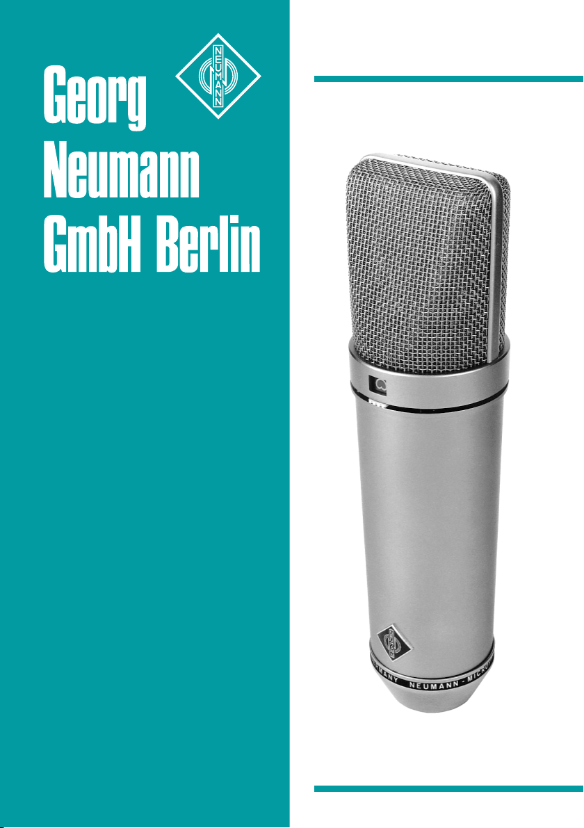
Die Zuordnung der Mikrophonanschlüsse entspricht
DIN 45 599, Kennzeichen „I“ bzw. IEC 268-12 (pin
conn. 130-x-IEC 02).
Die Modulationsadern liegen an Stift 2 und 3, die Abschirmung an Stift 1. Bei einem Schalldruckanstieg vor
der vorderen Mikrophonmembran tritt an Stift 2 eine
positive Spannung auf.
The directional characteristics “omni”, “cardioid” or “figure-8” are set with a slider switch on the front of the
microphone. A window above this switch shows the
setting by symbols. In the “cardioid” and “figure-8” positions the frequency response of the transmission factor
is practically linear for perpendicular sound incidence,
even in the upper audio frequency range. The microphone is thus particularly suitable for use at short distances from the sound source without an unnaturally
sharp sound impression.
A second slider switch located on the rear of the microphone introduces a preattenuation of about 10 dB
in the circuit. The microphone will handle sound pressure levels of up to 127 dB (corresponding to a sound
pressure of 45 Pa) without distortion.
To avoid structure born or wind noise, an electrical highpass filter in the U 87 Ai clips sub-audio frequencies.
Operating the third switch makes the sign visible in its corresponding cutout window and introduces a low frequency roll-off. Low frequency interfering
noises are thus attenuated at the input of the microphone amplifier. The unavoidable emphasis on bass
notes which occurs in all pressure-gradient microphones during close talking (proximity effect) is compensated to such an extent that a uniform frequency
response is produced in the “cardioid” position for a
talking distance of 30– 40 cm and in the “figure-8” position for a distance of 15–20 cm.
The microphone is largely immune to parasitic alternating currents in the cable shield, ac-induced hum and
interference caused by radio and TV transmitters and
radar equipment due to filtering in its output line and a
specially constructed output transformer with high common mode rejection and a static shield winding.
2. Microphone Versions and
Output Wiring
These versions are available:
UU
8787
AiAi
U
87
Ai ................................. ni ................................ Cat. No. 07022
UU
8787
AiAi
Standard version with male 3-pole connector insert
and satin nickel finish. Requires XLR 3 F cable connector.
Microphone wired per IEC 268-12 (pin conn. 130-xIEC 02) or DIN 45 599 I, respectively:
Modulation is connected to pins 2 and 3, the shield
to pin 1. A sudden sound pressure rise in front of
the front membrane causes a positive voltage to appear at pin 2.
2
3
Page 3

Das U 87 Ai hat einen elektrischen Innenwiderstand
von 200 Ohm. Der Eingangswiderstand des nachfolgenden Verstärkers sollte möglichst fünfmal so groß
oder größer sein, also ≥ 1000 Ohm.
UU
8787
AiAi
mtmt
U
87
Ai
mt ......................... sw .............................Best.-Nr. 07023
UU
8787
AiAi
mtmt
Wie oben, jedoch schwarzmatte Oberfläche.
3. Mikrophonkabel
Die höchste zulässige Kabellänge zwischen Mikrophon
und Verstärker beträgt etwa 300 m. Bei größeren Kabellängen beeinflußt die Kabelkapazität den Frequenzgang und führt in Verbindung mit der Streuinduktivität
des Mikrophonübertragers zunächst zu einem Anstieg
am oberen Ende des Übertragungsbereiches.
Für das Mikrophon U 87 Ai stehen folgende Kabel zur
Verfügung:
ICIC
33
mtmt
IC
3
mt .................................. sw ............................. Best.-Nr. 06543
ICIC
33
mtmt
10 m langes Mikrophonkabel, Durchmesser 5 mm, mit
Doppeldrallumspinnung als Abschirmung. Schwarz-matte 3-polige XLR-Steckverbinder. Führt am Ausgang des
Netzgerätes die Modulation weiter.
ICIC
3131
mt (5mt (5
IC
ICIC
5 m langes Mikrophonkabel, Durchmesser 4,5 mm, mit
Doppeldrallumspinnung als Abschirmung. Schwarzmatte 3-polige XLR-Steckverbinder. Zur Vermeidung von
Reibgeräuschen bei der Verwendung an der Angel
oder an Kunststoffdurchführungen (z.B. bei Windschutzkörben) ist das Kabel textilumsponnen.
ICIC
IC
ICIC
ICIC
IC
ICIC
10 m langes Mikrophonkabel für Mikrophone mit
Gewindeanschluß, Durchmesser 5 mm, mit Doppeldrallumspinnung als Abschirmung. Dreh- und schwenkbares Stativgelenk SGCD 3 (mt), 3-polige XLR-Steckverbinder, der Gewindeanschluß hat 5/8"-27-Gang. Ein
Adapter für 1/2"- und 3/8"-Gewindezapfen wird mitgeliefert.
ACAC
AC
ACAC
Adapterkabel mit einer 5-poligen XLR-Buchse und einem 3,5 mm Stereoklinkenstecker, unsymmetrisch, für
den Anschluß des 5-poligen XLR-Ausganges des Speisegerätes BS 48 i-2 oder der Matrixbox MTX 191 A
an Geräte mit 3,5 mm Stereoklinkenbuchse. Vorgesehen für alle Mikrophone der Serien fet 80/100 und
KM 100 F mit Ausnahme der Ausgangsstufe KM 100
und des GFM 132.
m)m)
31
mt (5
m) ............... sw .............................Best.-Nr. 06570
3131
mt (5mt (5
m)m)
44
(10(10
m)m)
4
(10
m) ........................ ni ...............................Best.-Nr. 06547
44
(10(10
m)m)
44
mt (10mt (10
m)m)
4
mt (10
m) ............... sw .............................Best.-Nr. 06557
44
mt (10mt (10
m)m)
22 (0,322 (0,3
m)m)
22 (0,3
m) .......................................................Best.-Nr. 06598
22 (0,322 (0,3
m)m)
The U 87 Ai has an electrical source impedance
of 200 ohms. The input impedance of the following
amplifier should be at least five times as great,
i.e. ≥ 1000 ohms.
UU
8787
AiAi
mtmt
U
87
Ai
mt ......................... blk.............................. Cat. No. 07023
UU
8787
AiAi
mtmt
As above, but with matt black finish.
3. Microphone Cables
The cable length between microphone and following
preamplifier should not exceed 300 m (980 ft.). The
capacitance of greater cable lengths could affect the frequency response and, in conjunction with the leakage inductance of the microphone’s output transformer, would
result in a rise at the upper end of the frequency range.
The following cables are available for the U 87 Ai microphone:
ICIC
33
mtmt
IC
3
mt .................................. blk .............................. Cat. No. 06543
ICIC
33
mtmt
10 m long microphone cable, 5 mm in diameter, with
double twist (double helix) braiding as shield. Threepin XLR connectors, matt black. For feeding the audio
signal to mixing consoles, etc.
ICIC
3131
mt (5mt (5
IC
ICIC
5 m long microphone cable, 4.5 mm in diameter, with
double twist braiding for screening. 3-pin XLR connectors, matte black. This cable is textile-braided to
avoid frictional noise due to the handling of booms or
plastic leadings (for example in windscreens).
ICIC
IC
ICIC
ICIC
IC
ICIC
10 m long microphone cable, 5 mm in diameter, with
double twist braiding for screening. 3-pin XLR connectors and SGCD 3 rotatable swivel mount. It has a
5/8"-27 female thread that can be fastened to tripods.
A threaded adapter for 1/2"- and 3/8" studs is included. Designed for microphones with a thread.
ACAC
AC
ACAC
Adapter cable with a 5-pin XLR connector on one
end and an unbalanced 3.5 mm stereo jack on the
other end. It is used to connect the 5-pin XLR output of the BS 48 i-2 power supply or the MTX 191 A
matrix amplifier to units with a 3.5 mm stereo input.
It is designed for all microphones of the fet 80/100
series and KM 100 F, excluding the KM 100 and the
GFM 132.
m)m)
31
mt (5
m) ............... blk .............................. Cat. No. 06570
3131
mt (5mt (5
m)m)
44
(10(10
m)m)
4
(10
m) ....................... ni ................................ Cat. No. 06547
44
(10(10
m)m)
44
mt (10mt (10
m)m)
4
mt (10
m) ............... blk .............................. Cat. No. 06557
44
mt (10mt (10
m)m)
22 (0.322 (0.3
m)m)
22 (0.3
m) ........................................................ Cat. No. 06598
22 (0.322 (0.3
m)m)
ACAC
25 (0,325 (0,3
AC
ACAC
Adapterkabel mit einer 3-poligen XLR-Buchse und einem 6,3 mm Monoklinkenstecker, unsymmetrisch, für
den Anschluß des 3-poligen XLR-Ausganges eines Speisegerätes BS 48 i oder N 48 i-2 an Geräte mit 6,3 mm
Monoklinkenbuchse. Vorgesehen für alle fet 80/100Mikrophone und KM 100 F mit Ausnahme der Ausgangsstufe KM 100 und des GFM 132.
ACAC
AC
ACAC
Y-Kabel mit einer 5-poligen XLR-Buchse und zwei
6,3 mm Monoklinkensteckern, unsymmetrisch, für den
Anschluß des 5-poligen XLR-Ausganges eines Speisegerätes BS 48 i-2 oder der Matrixbox MTX 191 A an
Geräte mit 6,3 mm Monoklinkenbuchsen. Vorgesehen
für alle fet 80/100-Mikrophone und KM 100 F mit Ausnahme von KM 100 und GFM 132.
Andere Kabellängen sind auf Wunsch lieferbar.
m)m)
25 (0,3
m) .......................................................Best.-Nr. 06600
25 (0,325 (0,3
m)m)
27 (0,327 (0,3
m)m)
27 (0,3
m) .......................................................Best.-Nr. 06602
27 (0,327 (0,3
m)m)
4. Stromversorgung
4.1 Die Phantomspeisung
Das Mikrophon U 87 Ai wird mit 48 V phantomgespeist (P48, IEC 1938).
Bei der Phantomspeisung fließt der Speisestrom vom
positiven Pol der Spannungsquelle über die elektrische
Mitte der beiden Modulationsadern zum Mikrophon. Er
wird hierzu über zwei gleich große Widerstände beiden Tonadern gleichsinnig zugeführt. Die Rückleitung
des Gleichstroms erfolgt über den Kabelschirm. Der
Einfluß von Störspannungen, die der Speisegleichspannung überlagert sind, auf die Ausgangsspannung des
Mikrophons wird dadurch um das Maß der Unsymmetriedämpfung herabgesetzt, bei Neumann-Mikrophonen
um mehr als 60 dB. Mit der Phantomspeisung ist eine
kompatible Anschlußtechnik möglich, weil zwischen
beiden Modulationsadern keine Potentialdifferenz besteht: Auf die Anschlußdosen können wahlweise auch
dynamische Mikrophone oder Bändchenmikrophone
sowie die Modulationskabel röhrenbestückter Kondensator-Mikrophone geschaltet werden, ohne daß die
Speisegleichspannung abgeschaltet werden muß.
4.2 Tragbare Netzgeräte
Für die Stromversorgung sind alle P48-Netzgeräte
(IEC 1938) geeignet. Das entsprechende NeumannP48-Netzgerät hat die Bezeichnung N 48 i-2. Es ist
zur Stromversorgung zweier Mono-Kondensatormikrophone oder eines Stereomikrophons mit 48 V ± 1 V,
maximal 2 x 5 mA geeignet.
AC 25 (0.3 m)AC 25 (0.3 m)
AC 25 (0.3 m) ........................................................ Cat. No. 06600
AC 25 (0.3 m)AC 25 (0.3 m)
Adapter cable with 3-pin XLR connector and a 6.3 mm
monojack, unbalanced. It is used to connect 3-pin XLR
outputs of the BS 48 i or N 48 i-2 power supplies to
units with a 6.3 mm monojack input. Designed for all
microphones of the fet 80/100 series and KM 100 F,
excluding the KM 100 output stage and the GFM 132
boundary-layer microphone.
AC 27 (0.3 m)AC 27 (0.3 m)
AC 27 (0.3 m) ........................................................ Cat. No. 06602
AC 27 (0.3 m)AC 27 (0.3 m)
Y-cable with a 5-pin XLR connector and two 6.3 mm
monojacks, unbalanced. It is used to connect 5-pin
XLR outputs of the BS 48 i-2 power supply or the
MTX 191 A matrix amplifier to units with 6.3 mm
monojack inputs. Designed for all microphones of the
fet 80/100 series and KM 100 F, excluding the KM 100
and the GFM 132.
Custom-made cables are available on request.
4. Power Supply
4.1 Phantom Powering
The U 87 Ai microphone operates on 48 volt phantom power (P48, IEC 1938).
With phantom powering the dc from the positive supply
terminal is divided via two identical resistors, one half
of the dc flowing through each audio (modulation) conductor to the microphone, and returning to the voltage source via the cable shield. As a consequence, the
effect of dc supply voltage noise super-imposed on the
microphone output voltage is reduced by the common
mode rejection factor. Neumann microphones have a
common mode rejection factor exceeding 60 dB. Phantom powering provides a fully compatible connecting
system, since no potential differences exist between the
two audio conductors. Studio outlets so powered will
therefore also accept dynamic microphones and ribbon
microphones as well as the modulation conductors of
tube-equipped condenser microphones without the
need to switch off the dc supply voltage. No harm is
done even if a phantom power supply is connected to
an outlet which is centrally phantom powered.
4.2 Portable AC Supply Units
Any P48 power supply unit (IEC 1938) is suitable.
The Neumann P48 power supply unit is designated
N 48 i-2 to power two mono condenser microphones
or one stereo microphone at 48 V ± 1 V, max.
2 x 5 mA.
4
5
Page 4
Siehe Neumann-Druckschrift 68832... „48 V-Phantomspeisegeräte“.
NN
4848
i-2 (230i-2 (230
N
48
NN
4848
NN
4848
N
48
NN
4848
4.3 Batteriespeisung
Das Mikrophon U 87 Ai besitzt im Gegensatz zum
Vorgängermodell U 87 i keine eingebaute Batteriespeisung mehr. Für die netzunabhängige Stromversorgung
von Neumann-Kondensatormikrophonen steht das Batteriegerät BS 48 i (für ein Mikrophon) oder BS 48 i-2
(für zwei Mikrophone ) zur Verfügung.
Beide Geräte liefern 48 V ± 1 V, maximal je 5 mA
und werden jeweils von einer 9-Volt-Blockbatterie
Typ IEC 6 F 22 gespeist. Siehe Neumann-Druckschrift
88832... „48 V-Phantomspeisegeräte“.
Die Zuordnung der Mikrophonanschlüsse und die Po-
larität der Modulationsadern ist am Ausgang der Speisegeräte die gleiche wie am Mikrophon.
BSBS
4848
BS
48
BSBS
4848
BSBS
4848
BS
48
BSBS
4848
V)V)
i-2 (230
V) ............ sw .............................Best.-Nr. 06500
i-2 (230i-2 (230
V)V)
i-2 (117i-2 (117
V)V)
i-2 (117
V) ............ sw .............................Best.-Nr. 06502
i-2 (117i-2 (117
V)V)
ii
i (für ein Mikrophon) ......................... Best.-Nr. 06494
ii
i-2i-2
i-2
(für zwei Mikrophone) ............... Best.-Nr. 06496
i-2i-2
5. Betrieb an unsymmetrischen oder
mittengeerdeten Eingängen
Die 48 V-Phantomspeisegeräte BS 48 i, BS 48 i-2 und
N 48 i-2 haben gleichspannungsfreie Ausgänge, so daß
für den Anschluß an einen unsymmetrischen Eingang
kein Übertrager erforderlich ist.
Beim U 87 Ai ist Pin 2 die heiße Phase, und Pin 3
muß für unsymmetrische Eingänge an Masse gelegt
werden (siehe Abbildung 1).
Bei vielen anderen als
den o.g. Phantomspeisegeräten liegen nicht nur
die Modulationsleitungen
zum Mikrophon auf dem
Potential der Speisespannung von +48 V, sondern
auch die vom Speisegerät abgehenden Modulationsleitungen. Für die in
der Studiotechnik allgemein üblichen symmetrischen
und erdfreien Verstärker- und Mischpulteingänge ist
dies ohne Bedeutung.
Dagegen wird die Speisespannung beim Anschluß an
unsymmetrische oder mittengeerdete Verstärkereingänge kurzgeschlossen, und es ist kein Betrieb möglich.
Abbildung / Figure 1
See Neumann bulletin No. 68832... “Phantom 48 Vdc
Power Supplies”.
NN
4848
i-2 (230i-2 (230
N
48
NN
4848
NN
4848
N
48
NN
4848
4.3 Battery Operation
In contrast to its predecessor U 87 i, the U 87 Ai microphone has no built-in battery current supply. If a
mains power source is not available, power can be supplied by one of the units BS 48 i (for one microphone)
or BS 48 i-2 (for two microphones).
Both units deliver 48 V ± 1 V, at 5 mA maximum,
and are powered by a 9-volt monobloc battery type
IEC 6 F 22. See Neumann bulletin No. 68832... “Phantom 48 Vdc Power Supplies”.
Modulation polarity at the power supply output is identical with that at the microphone.
BSBS
4848
BS
48
BSBS
4848
BSBS
4848
BS
48
BSBS
4848
V)V)
i-2 (230
V) ............ blk .............................. Cat. No. 06500
i-2 (230i-2 (230
V)V)
i-2 (117i-2 (117
V)V)
i-2 (117
V) ............ blk .............................. Cat. No. 06502
i-2 (117i-2 (117
V)V)
ii
i (for one microphone) ........................ Cat. No. 06494
ii
ii
-2-2
i
-2 (for two microphones) .................Cat. No. 06496
ii
-2-2
5. Operation with Unbalanced or
Center Tap Grounded Inputs
The 48 V phantom powering units BS 48 i, BS 48 i-2
and N 48 i-2 have dc-free outputs, so that no transformer is required for connecting to an unbalanced
input.
In the case of the U 87 Ai condenser microphone
pin 2 is the hot phase, and pin 3 must be connected
to earth (see Fig. 1).
In the case of many other phantom powering
units (except those mentioned above), not only
the modulation leads to
the microphone, but also
the outgoing modulation
leads from the powering
unit, are at the potential
(+48 V). This is of no significance for the balanced,
floating amplifier and mixing console inputs in general
studio use.
On the other hand, the feed voltage will be shortcircuited when connected to unbalanced or center tap
grounded amplifier inputs, and no operation will be
possible.
of the feed voltage
Dann bestehen folgende Lösungsmöglichkeiten:
a) In mittengeerdeten Geräten mit Eingangsübertra-
ger (z.B. einige NAGRA-Geräte) kann die betreffende Erdverbindung fast immer ohne Nachteile für die
Funktion des Gerätes aufgetrennt werden.
b) In jede abgehende Modulationsleitung kann zur
Abblockung der 48 V-Gleichspannung eine RC-Kombination eingefügt werden (siehe Neumann-Information Nr. 84 221).
6. Zerlegen des Mikrophons und
Meßeingang
Nach Linksdrehen der Überwurfmutter am unteren Teil
des Mikrophons läßt sich das Gehäuserohr abziehen,
und es wird eine rote Buchse sichtbar. Über diese kann
in die zum Kapselfußpunkt führende Leitung eine Tonfrequenzspannung eingeschleift werden, die den Verstärkereingang über die Kapselkapazität in gleicher
Weise beaufschlagt, wie dies beim Auftreffen eines entsprechenden Schallwechseldruckes der Fall wäre.
Die meisten elektrischen Daten des Mikrophonverstärkers wie Verstärkung, Frequenzgang und Aussteuerbarkeit können so direkt überprüft werden. Der Eingangswiderstand des Meßeinganges ist ca. 600 Ohm.
Rot: zum Kapselfußpunkt.
Sollwerte für das U 87 Ai sind (Toleranz ± 1 dB):
Spannungsverstärkung
(1 kHz, Abschluß 1 kOhm ) ............................................ 0 dB
Rel. Verstärkung bei 40 Hz
(bezogen auf den Wert bei 1 kHz)........................... –3 dB
Rel. Verstärkung bei 40 Hz
(Schalter ) .................................................................. –18 dB
Rel. Verstärkung bei 16 kHz ......................................... –4 dB
Maximale Eingangswechselspannung
(1 kHz), bei der der Klirrfaktor
unter 0,5 % sein soll ................................................. 390 mV
Stromaufnahme bei 48 V ............................ 0,8 ± 0,05 mA
Störspannungen (DIN 45 405, CCIR 468-3;
0 dB : 0,775 V; Toleranz +1 dB):
Unbewerteter Störspannungspegel ................ –103 dB
Bewerteter Störspannungspegel ..................... –101 dB
qps
This can be circumvented as follows:
a) In center tap grounded equipment with input
transformer (e.g. some NAGRA units), the earth lead
can almost always be disconnected without affecting
the function of the equipment.
b) In every outgoing modulation lead, an RC network can be incorporated to block the 48 Vdc voltage
(See Neumann-Information no. 84 222).
6. Disassembling of the Microphone
and Test Input
Unscrew the large lower ring of the microphone; the
conical housing tube can then be withdrawn downwards
and a red socket can be seen. This socket enable an
audio frequency test signal to be applied to the amplifier input via the capsule capacitance in the same way
as a corresponding change in sound pressure.
Most of the electrical data of the microphone amplifier, such as gain, frequency response, self noise, and
modulability can thus be directly tested. Input impedance of the measuring input: 600 ohms approx.
Red: to capsule base-point.
The nominal values for the U 87 Ai are as follows
(tolerance: ± 1 dB):
Voltage gain
(1 kHz, 1 kOhm termination) ......................................... 0 dB
Rel. gain at 40 Hz,
(ref. 1 kHz) ............................................................................... –3 dB
Rel. gain at 40 Hz,
(switch ) ..................................................................... –18 dB
Rel. gain at 16 kHz .............................................................. –4 dB
Maximum input ac voltage (1 kHz)
at which the THD should be less
eff
qs
than 0,5 % .................................................................... 390 mV
Current consumption at 48 V .................0.8 ± 0.05 mA
Nominal self-noise level (CCIR 468-3,
Reference: 0.775 V, peak to peak, tolerance: +1 dB):
Unweighted self-noise level ................................ –103 dB
Weighted self-noise level ................................... –101 dB
rms
qps
qs
6
7
Page 5

7. Technische Daten
7. Technical Specifications
8. Einige Hinweise zur Pflege von
Mikrophonen
8. Some Remarks on Microphone
Maintenance
Akust. Arbeitsweise ........... Druckgradientenempfänger
Richtcharakteristik ...................................... Kugel/Niere/Acht
Übertragungsbereich ....................................... 20 Hz...20 kHz
Feldbetriebsübertragungs-
faktor1) bei 1 kHz ....................... 20/28/22 mV/Pa ± 1 dB
Nennimpedanz ............................................................ 200 Ohm
Nennabschlußimpedanz ...................................... 1000 Ohm
Geräuschpegelabstand
CCIR 468-3............................................................... 68/71/69 dB
Geräuschpegelabstand
DIN/IEC 651 ............................................................79/82/80 dB
Ersatzgeräuschpegel
CCIR 468-3............................................................... 26/23/25 dB
Ersatzgeräuschpegel
DIN/IEC 651 ...................................................... 15/12/14 dB-A
Grenzschalldruckpegel bei 1 kHz für
0,5 % Klirrfaktor2) (Niere) ............................................ 117 dB
mit Vordämpfung .............................................................. 127 dB
Max. Ausgangsspannung dabei ............................... –6 dBu
Speisespannung
Speisestrom
3)
.................................................................. 48 V ± 4 V
3)
........................................................................................ 0,8 mA
Mindestbetriebszeit mit BS 48 i ....................... ca. 20 Std.
Erforderliche Kabelkupplung .....................................XLR 3 F
Gewicht ...................................................................................... 500 g
Durchmesser ..................................................................... 56 mm
Länge ..................................................................................... 200 mm
0 dB 20 µPa
1)
bei 1 kHz an 1 kOhm Nennabschlußimpedanz.
1 Pa 94 dB SPL.
2)
Klirrfaktor des Mikrophonverstärkers bei einer Eingangsspannung, die der
von der Kapsel beim entsprechenden Schalldruck abgegebenen Spannung
entspricht.
3)
Phantomspeisung (P48, IEC 1938).
Acoustical operating principle .............Pressure gradient
transducer
Polar pattern ...................................... Omni/cardioid/figure-8
Frequency range ................................................20 Hz...20 kHz
Sensitivity at 1 kHz
1)
..................... 20/28/22 mV/Pa ± 1 dB
Rated impedance ....................................................... 200 ohms
Rated load impedance .......................................... 1000 ohms
S/N ratio
CCIR 468-3............................................................... 68/71/69 dB
S/N ratio
DIN/IEC 651 ............................................................79/82/80 dB
Equivalent SPL
CCIR 468-3............................................................... 26/23/25 dB
Equivalent SPL
IEC/DIN 651 ....................................................... 15/12/14 dB-A
Max. SPL for 0.5 % THD2) at
1 kHz (cardioid) ................................................................. 117 dB
with sensitivity reduction ............................................. 127 dB
Max. output voltage ........................................................ –6 dBu
Supply voltage
Current consumption
3)
....................................................................... 48 V ± 4 V
3)
............................................................. 0.8 mA
Minimum operating time
with BS 48 i.................................................... approx. 20 hours
Required cable connector .........................................XLR 3 F
Weight ...............................................................500 g (17.7 ozs.)
Diameter .................................................................. 56 mm (2.2")
Length .....................................................................200 mm (7.9")
0 dB 20 µPa
1)
at 1 kHz into 1 kOhm rated load impedance.
1 Pa 94 dB SPL.
2)
THD of microphone amplifier at an input voltage equivalent to the
capsule output at the specified SPL.
3)
Phantom powering (P48, IEC 1938).
Staubschutz verwenden: Mikrophone, die nicht im Einsatz sind, sollte man nicht auf dem Stativ einstauben
lassen. Mit einem Staubschutzbeutel (nicht fusselnd)
wird dies verhindert. Wird ein Mikrophon längere Zeit
nicht verwendet, sollte es in einem Schrank bei normalem Umgebungsklima aufbewahrt werden.
Popschutz verwenden: Ein Popschutz hat nicht nur die
Aufgabe, bei Gesangsaufnahmen die Entstehung von
Poplauten zu verhindern. Er vermeidet auch effizient,
daß sich von der Feuchtigkeit des Atems bis hin zu
Essensresten unerwünschte Partikel auf der Membran
ablagern.
Keine überalterten Windschutze verwenden: Auch
Schaumstoff altert. Das Material kann brüchig und krümelig werden. Anstatt das Mikrophon zu schützen, kann
er dann zur Verunreinigung der Mikrophonkapsel führen. Überalterte Windschutze also bitte entsorgen.
Funktionstest: Moderne Kondensatormikrophone nehmen durch lautes Ansprechen keinen Schaden. Zur
Kontrolle, ob ein solches Mikrophon angeschlossen ist,
sollte man es aber keinesfalls anpusten oder anpoppen, da dies einem akustischen Signal von mehr
als 140 dB (!) entsprechen kann. Normale Sprache genügt zum Funktionstest völlig.
Selbsthilfe kann teuer sein! Leider kommt es doch vor,
daß durch eine Selbstreparatur mehr beschädigt als
behoben wird. Insbesondere das Reinigen verschmutzter Kapseln erfordert viel Erfahrung und die Hand eines Fachmanns. Der Lackschutz auf Platinen zeigt u.a.
an, daß dort nicht gelötet werden darf. Einige Bauteile
sind speziell selektiert und können nicht durch Material
von der Stange ersetzt werden. Um unnötige Kosten
zu vermeiden, empfiehlt sich die Einsendung an unsere
Vertretungen oder an uns.
Inspektion durchführen lassen: Regelmäßiges Durchchecken des Mikrophonbestands, wie es einige Schauspielhäuser und Rundfunkanstalten praktizieren, kann
bei der Früherkennung von Schäden helfen. Leichte
Verschmutzungen lassen sich eher beseitigen, als eine
untrennbar in die Membran eingebrannte Nikotinschicht. Insbesondere bei Mikrophonen im Verleih und
in verunreinigenden Umgebungen empfiehlt sich die
regelmäßige Kontrolle, deren Kosten im Vergleich zu
einer aufwendigen Reparatur sehr gering sind.
Use the dust cover: Microphones not in operation
should not be left on the floor stand unprotected. With
a non-fluffy dust cover the microphone can be protected from dust settling on the capsule. When not in
use for a longer spell, the microphone should be stored
in a closet at standard climatic conditions.
Use a pop screen: The pop screen not only eliminates
the plosive pop noises in vocal recordings. In closemiked vocal applications it also efficiently protects the
diaphragm from almost anything, including breath humidity down to food particles.
Do not use overaged wind shields: Even the foam material of wind shields ages. With very old wind shields,
the material decays and becomes brittle. The particles
can then settle on the diaphragm. So, please dispose
of overaged wind shields.
Function testing: Modern condenser microphones cannot be harmed by very high sound pressure levels. Still,
there is no need for pop-testing to see if a microphone
is working and pulled up on the console. Normal speech
is good enough, and pop-testing can produce sound
pressure levels exceeding 140 dB!
Do-it-yourself can be expensive: Do-it-yourself repairs
can sometimes be more harmful than beneficial. Especially cleaning soiled capsules does take a skilled hand
and quite some experience. Furthermore, the protective lacquer shows the parts of the printed circuit boards
where e.g. soldering should be avoided. Other parts
may be specifically selected and cannot be replaced by
standard components. To avoid unnecessary cost, we
recommend sending in defective microphones to our
distributors, or to us directly, for servicing.
Regular servicing: As some theaters and broadcasters
do on a regular basis, sending in microphones for servicing can help in early recognition of damages. Slight
soiling can be removed much easier than some nicotine layer firmly embedded in the diaphragm. Especially
with microphones on loan and in dustier / smokier environments regular checking proves beneficial, as the
cost is rather small compared to a major overhaul.
8
9
Page 6
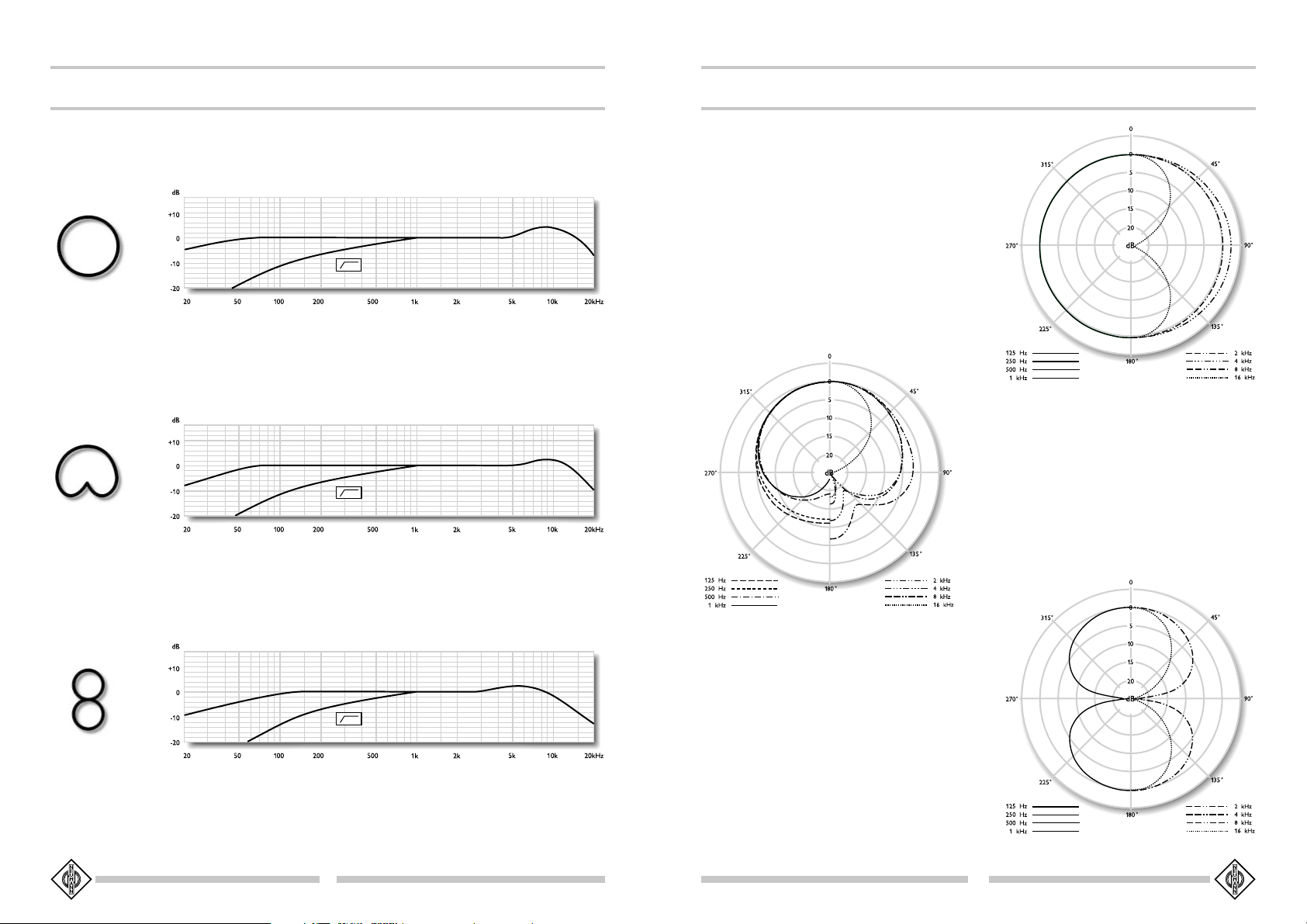
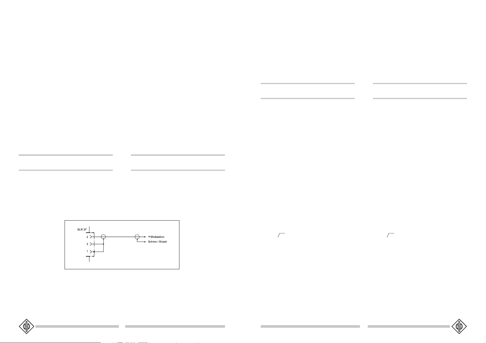
9. Frequenzgänge und Polardiagramme
Frequency Responses and Polar Pattern
°
°
gemessen im freien Schallfeld nach IEC 60268-4
measured in free-field conditions (IEC 60268-4)
10
°
11
Page 7

10. Zubehör
Weitere Artikel sind im Katalog „Zubehör“ beschrieben.
10.1 Stativgelenke
SGSG
367367
SG
367 ................................... ni ...............................Best.-Nr. 06143
SGSG
367367
SGSG
367367
mtmt
SG
367
mt .......................... sw ............................. Best.-Nr. 06145
SGSG
367367
mtmt
Das Stativgelenk SG 367 kann an die Mikrophone
U 87 i und U 87 Ai geschraubt werden und dient bei
Verwendung des Kabels IC 3 zur Befestigung dieser
Mikrophone auf einem Stativ, der Gewindeanschluß hat
5/8"-27-Gang. Ein Reduzierstück zur Verbindung mit
1/2"- und 3/8"-Gewindezapfen wird mitgeliefert.
10.2 Tisch- und Fußbodenständer
MFMF
33
MF
3 ........................................ sw ............................. Best.-Nr. 07321
MFMF
33
Der Mikrophonfuß MF 3 ist ein Tischständer mit Eisenfuß, 1,6 kg schwer, Durchmesser 110 mm. Der Ständer
ist schwarzmatt lackiert und steht gleitfest auf einer Moosgummischeibe. Ein umwendbarer Gewindezapfen und ein
mitgeliefertes Reduzierstück ermöglichen die Verwendung
für 1/2"- und 3/8"-Gewindeanschlüsse.
MFMF
44
MF
4 ........................................ sw ............................. Best.-Nr. 07339
MFMF
44
Der Mikrophonfuß MF 4 ist ein Fußbodenständer aus
Grauguß, ca. 2,6 kg schwer, Durchmesser 160 mm. Der
Ständer ist schwarzmatt lackiert und steht gleitfest auf einem Gummiring. Ein umwendbarer Gewindezapfen und
ein mitgeliefertes Reduzierstück ermöglichen die Verwendung für 1/2"- und 3/8"-Gewindeanschlüsse.
GG
3535
G
35 ........................................ ni ...............................Best.-Nr. 07244
GG
3535
Galgenaufsatz mit verschiebbarem Gegengewicht und
ausziehbarer Abstützung für das Mikrophonstativ M 35,
vernickelt. Die seitliche Ausladung ist stufenlos bis maximal 2,5 m einstellbar. Gewicht 8 kg. Der schwenkbare Anschluß zur Befestigung auf dem Stativ M 35
hat 1/2"-Gewinde.
MM
3131
M
31 ....................................... ni ...............................Best.-Nr. 07232
MM
3131
Fußbodenständer mit dreibeinigem, hammerschlageffektlackiertem Gußfuß (RAL 7001). Das Rohr ist vernickelt und zur Trittschalldämmung in einer Gummimuffe
gelagert. Die Höhe ist zwischen 1 m und 1,8 m einstellbar. Der Fußbodenständer hat einen 3/8"-Gewindezapfen. Gewicht 4,1 kg.
10. Accessories
Further articles are described in the catalog “Accessories”.
10.1 Stand Mounts
SGSG
367367
SG
367 ................................... ni ................................ Cat. No. 06143
SGSG
367367
SGSG
367367
mtmt
SG
367
mt .......................... blk .............................. Cat. No. 06145
SGSG
367367
mtmt
The SG 367 swivel mount can be screwed to the
bottom part of the U 87 i and U 87 Ai microphones.
Employing the IC 3 cable these microphones can then
be fastened to tripods. The swivel mount has a 5/8"27 thread, a threaded adapter for the connection with
1/2" and 3/8" is included.
10.2 Table and Floor Stands
MFMF
33
MF
3 ........................................ blk .............................. Cat. No. 07321
MFMF
33
Table stand with iron base, 1.6 kg, 110 mm in diameter. The table stand has a matte black finish and rests
on a nonskid rubber disk attached to the bottom. A
reversible stud and a reducer for 1/2" and 3/8" threads
are also supplied.
MFMF
44
MF
4 ........................................ blk .............................. Cat. No. 07339
MFMF
44
Floor stand with grey cast iron base, 2.6 kg, 160 mm
in diameter. The floor stand has a matte black finish
and rests on a nonskid rubber disk attached to the bottom. A reversible stud and a reducer for 1/2" and 3/8"
threads are also supplied.
GG
3535
G
35 ........................................ ni ................................ Cat. No. 07244
GG
3535
Boom attachment with movable counterbalance and
support for the M 35 floor stand, nickel-plated. The
extension to the side is continuously adjustable to a
maximum of 2.5 m. Weight 8 kg. It has a 1/2" swivelable female thread that can be fastened to the M 35
floor stand.
MM
3131
M
31 ....................................... ni ................................ Cat. No. 07232
MM
3131
Floor stand with tripod, hammer tone lacquered castiron base (RAL 7001). The tube is nickel-plated and
shock-mounted for dampening impact sound. The
height is adjustable between 1 m and 1.8 m. The floor
stand has a 3/8" threaded stud, weight 4.1 kg.
MM
3232
M
32 ....................................... ni ............................... Best.-Nr. 07237
MM
3232
Zusammenklappbarer Fußbodenständer, vernickelt. Die
Transportlänge beträgt 0,9 m. Die Höhe ist zwischen
1 m und 1,8 m einstellbar. Der Fußbodenständer hat
einen 3/8"-Gewindezapfen. Gewicht 2,7 kg.
MM
3535
M
35 ....................................... ni ............................... Best.-Nr. 07242
MM
3535
M 35 ist ein sehr stabiler Klappständer, vernickelt, Gewicht 9,3 kg. Maximale Höhe 5 m, minimale Arbeitshöhe 1,4 m, Länge zusammengelegt 1,65 m. Der Ständer ist vernickelt und hat einen 1/2"-Gewindezapfen.
MM
3636
M
36 ....................................... s w/ni ....................... Best.-Nr. 07351
MM
3636
M 36 ist ein sehr stabiler Klappständer, Aluminium,
Gewicht 8,2 kg. Maximale Höhe 4,5 m, minimale Arbeitshöhe 1,75 m. Der Ständer hat einen 1/2"-Gewindezapfen.
MM
212212
M
212 .................... sw/ni ............. Best.-Nr. 07251 + 07248
MM
212212
M 212 ist ein Galgenstativ. Es handelt sich um eine
Kombination aus dem Fußbodenständer M 214/1 und
dem Galgenaufsatz M 212 c.
10.3 Stativverlängerungen
Die Stativverlängerungen STV... werden zwischen Fußbodenständer und Mikrophonhalterung geschraubt. Dadurch entstehen unterschiedlich hohe Tisch- oder Fußbodenstative.
Die STV... haben eine Länge von 40, 200, 400 oder
600 mm. Durchmesser: 19 mm.
STVSTV
44
STV
4 ...................................... sw ............................. Best.-Nr. 06190
STVSTV
44
STVSTV
2020
STV
20 ................................... sw ............................. Best.-Nr. 06187
STVSTV
2020
STVSTV
4040
STV
40 ................................... sw ............................. Best.-Nr. 06188
STVSTV
4040
STVSTV
6060
STV
60 ................................... sw ............................. Best.-Nr. 06189
STVSTV
6060
10.4 Elastische Aufhängung
Um mechanische Erschütterung fernzuhalten, empfiehlt
sich die Verwendung einer elastischen Mikrophonaufhängung.
EAEA
8787
EA
87 ..................................... n i ............................... Best.-Nr. 07297
EAEA
8787
EAEA
8787
mtmt
EA
87
mt ............................ sw ............................. Best.-Nr. 07298
EAEA
8787
mtmt
Die EA 87 ist für das Mikrophon U 87 Ai vorgesehen. Der schwenkbare Gewindeanschluß zur Befestigung auf Stativen hat 5/8"-27-Gang. Ein Reduzierstück
zur Verbindung mit 1/2"- und 3/8"-Gewindezapfen wird
mitgeliefert.
MM
3232
M
32 ....................................... ni ................................ Cat. No. 07237
MM
3232
Folding floor stand, nickel-plated. When folded the
length is 0.9 m. The height is adjustable between 1 m
and 1.8 m. The floor stand has a 3/8" threaded stud,
weight 2.7 kg.
MM
3535
M
35 ....................................... ni ................................ Cat. No. 07242
MM
3535
M 35 is an extremely sturdy folding stand, nickel-plated, weight 9.3 kg. Maximum height 5 m, minimum
working height 1.4 m, When folded length is 1.65 m.
The stand has a 1/2" threaded stud.
MM
3636
M
36 ....................................... blk/ni ....................... Cat. No. 07351
MM
3636
M 36 is an extremely sturdy folding stand, aluminium, weight 8.2 kg. Maximum height 4.5 m, minimum
working height 1.75 m. The stand has a 1/2" threaded stud.
MM
212212
M
212 .................................... blk/ni Cat. No. 07251 + 07248
MM
212212
M 212 is a microphone boom stand. It is a combination of M 214/1 folding floor stand and M 212 c boom
attachment.
10.3 Stand Extensions
The STV... stand extensions are used between microphone and floor stands to provide table or floor stands
of variable heights.
The STVs are 40, 200, 400 or 600 mm long. Diameter: 19 mm.
STVSTV
44
STV
4 ...................................... blk .............................. Cat. No. 06190
STVSTV
44
STVSTV
2020
STV
20 ................................... blk .............................. Cat. No. 06187
STVSTV
2020
STVSTV
4040
STV
40 ................................... blk .............................. Cat. No. 06188
STVSTV
4040
STVSTV
6060
STV
60 ................................... blk .............................. Cat. No. 06189
STVSTV
6060
10.4 Elastic Suspension
The use of an elastic suspension is recommended to
prevent the microphone from being exposed to strong
mechanical vibrations caused by structure borne shock
waves.
EAEA
8787
EA
87 ..................................... n i ................................ Cat. No. 07297
EAEA
8787
EAEA
8787
mtmt
EA
87
mt ............................ blk .............................. Cat. No. 07298
EAEA
8787
mtmt
The EA 87 is designed for the U 87 Ai microphone.
It has a swivel mount with a 5/8"-27 female thread
that can be fastened to tripods. Included is a threaded adapter to connect to 1/2"- and 3/8" studs.
12
13
Page 8

10.5 Popschutz
PSPS
2020
PS
20 ...................................... sw ............................. Best.-Nr. 07346
PSPS
2020
Der Popschirm PS 20 bietet einen sehr wirksamen
Schutz vor den sogenannten Popgeräuschen. Er bestehen aus einem runden dünnen Holzrahmen, der beidseitig mit schwarzer Gaze bespannt ist.
Der um ca. 230° schwenkbare Stativanschlußstutzen hat
5/8"-27-Gang-Innengewinde mit einem Reduzierstück zur
Verbindung mit 1/2"- und 3/8"-Gewindezapfen.
Zum Lieferumfang gehört ein zweiseitig konterbarer
Gewindezapfen, um einen Popschirm z.B. an die Klammer MKV zu schrauben. Damit kann er an die Stativstangen oder an die Steckverbinder geklammert werden.
10.5 Popscreen
PSPS
2020
PS
20 ...................................... blk .............................. Cat. No. 07346
PSPS
2020
The PS 20 popshield provides excellent suppression
of so-called pop noise. It consists of a round, thin
wooden frame covered with black gauze on both sides.
The stand adaptor with 5/8"-27 female thread can be
altered by 230°. A reducer for connection to 1/2" and
3/8" studs is included.
For mounting a popshield to the MKV quick-release
clamp, a double-sided stud with locknut is included
in the supply schedule. Used in conjunction with the
MKV quick-release clamp the popshields can be attached to stands or connectors.
IC 3 mt
IC 31 mt
IC 4 (mt)
10.6 Mikrophon-Neigevorrichtung
MNVMNV
8787
MNV
87 ................................ n i ............................... Best.-Nr. 06804
MNVMNV
8787
MNVMNV
8787
mtmt
MNV
87
mt ....................... sw ............................. Best.-Nr. 06806
MNVMNV
8787
mtmt
Die Mikrophonneigevorrichtung MNV 87 besteht aus
einer Kabelhalterung und einen Gewindezapfen. Sie wird
in das Stativgelenk des Kabels IC 4 geschraubt (s. Kapitel 2.3) und ermöglicht dann die Einstellung der Mikrophonneigung bei frei am Kabel hängendem Mikrophon. Gewinde: 1/2"- oder 5/8"-27-Gang.
10.7 Schaumstoffwindschutz
WSWS
8787
WS
87 .................................... sw ............................. Best.-Nr. 06753
WSWS
8787
Durchmesser ca. 90 mm. Dämpfung des Windgeräusches ca. 26 dB. Dämpfung bei 15 kHz ca. 3 dB. Farbe schwarz.
Zum Vermeiden von Störgeräuschen, die bei Nahbesprechung, Windeinfluß oder z.B. bei schnellem
Schwenken des Mikrophongalgens auftreten können,
sind Windschutzeinrichtungen aus offenporigem Polyurethanschaum lieferbar. Diese Windschutzeinrichtungen erzeugen keine störenden Resonanzen und beeinflussen den Frequenzgang des Übertragungsmaßes
nur geringfügig.
10.6 Auditorium Hanger
MNVMNV
8787
MNV
87 ................................ n i ................................ Cat. No. 06804
MNVMNV
8787
MNVMNV
8787
mtmt
MNV
87
mt ....................... blk .............................. Cat. No. 06806
MNVMNV
8787
mtmt
The MNV 87 auditorium hanger consists of a cable
clamp and a stud with which it is screwed into the swivel
mount of the IC 4 cable (see chapter 2.3). The microphone can then be tilted as needed because it is
freely suspended from its own cable. Available with
1/2" or 5/8"-27 thread stud.
10.7 Foam Windscreen
WSWS
8787
WS
87 .................................... blk .............................. Cat. No. 06753
WSWS
8787
Diameter is approx. 90 mm. Suppression of wind noise
approx. 26 dB. Attenuation at 15 kHz approx. 3 dB.
Color black.
Open-cell polyurethane foam windscreens are available to guard against disturbances that may be caused
by wind, close-talking applications, or rapid boom movements. These windscreens have no disturbing resonances and only slightly affect the frequency response.
N 48 i-2
AC 25AC 22
BS 48 i
AC 27
BS 48 i-2
14
SG 367 (mt)
MF 3
15
MF 4
Page 9

G 35 M 31
M 32
M 35
M 212 EA 87 (mt)
PS 20
M 36
MNV 87 (mt) WS 87
STV...
Irrtümer und technische Änderungen vorbehalten • Errors excepted, subject to changes
Printed in Germany • Publ. 07/00 68820 / A 04
 Loading...