

Page 1

INSTALLATION/OPERATION
®
System 9760
Video Matrix Switching
Control System
C1572M (9/05)
Page 2

Page 3

Contents
Important Safety Instructions . . . . . . . . . . . . . . . . . . . . . . . . . . . . . . . . . . . . . . . . . . . . . . . . . . . . . . . . . . . . . . . . . . . . . . . . . . . . . . . . . . . . . . . . . . . .7
Regulatory Notices . . . . . . . . . . . . . . . . . . . . . . . . . . . . . . . . . . . . . . . . . . . . . . . . . . . . . . . . . . . . . . . . . . . . . . . . . . . . . . . . . . . . . . . . . . . . . . . . . . . .8
System Overview . . . . . . . . . . . . . . . . . . . . . . . . . . . . . . . . . . . . . . . . . . . . . . . . . . . . . . . . . . . . . . . . . . . . . . . . . . . . . . . . . . . . . . . . . . . . . . . . . . . . .9
System Setup . . . . . . . . . . . . . . . . . . . . . . . . . . . . . . . . . . . . . . . . . . . . . . . . . . . . . . . . . . . . . . . . . . . . . . . . . . . . . . . . . . . . . . . . . . . . . . . . . . . . . . .12
Description . . . . . . . . . . . . . . . . . . . . . . . . . . . . . . . . . . . . . . . . . . . . . . . . . . . . . . . . . . . . . . . . . . . . . . . . . . . . . . . . . . . . . . . . . . . . . . . . . . . . . .9
Models . . . . . . . . . . . . . . . . . . . . . . . . . . . . . . . . . . . . . . . . . . . . . . . . . . . . . . . . . . . . . . . . . . . . . . . . . . . . . . . . . . . . . . . . . . . . . . . . . . . . . . . . 10
CPU Controller and Components . . . . . . . . . . . . . . . . . . . . . . . . . . . . . . . . . . . . . . . . . . . . . . . . . . . . . . . . . . . . . . . . . . . . . . . . . . . . . . .10
Matrix Bay and Components . . . . . . . . . . . . . . . . . . . . . . . . . . . . . . . . . . . . . . . . . . . . . . . . . . . . . . . . . . . . . . . . . . . . . . . . . . . . . . . . . .10
Keyboards . . . . . . . . . . . . . . . . . . . . . . . . . . . . . . . . . . . . . . . . . . . . . . . . . . . . . . . . . . . . . . . . . . . . . . . . . . . . . . . . . . . . . . . . . . . . . . . . .10
Network Interface Unit . . . . . . . . . . . . . . . . . . . . . . . . . . . . . . . . . . . . . . . . . . . . . . . . . . . . . . . . . . . . . . . . . . . . . . . . . . . . . . . . . . . . . . .11
Optional Components . . . . . . . . . . . . . . . . . . . . . . . . . . . . . . . . . . . . . . . . . . . . . . . . . . . . . . . . . . . . . . . . . . . . . . . . . . . . . . . . . . . . . . . .11
Compatible Receivers . . . . . . . . . . . . . . . . . . . . . . . . . . . . . . . . . . . . . . . . . . . . . . . . . . . . . . . . . . . . . . . . . . . . . . . . . . . . . . . . . . . . . . . .11
System Setup Overview . . . . . . . . . . . . . . . . . . . . . . . . . . . . . . . . . . . . . . . . . . . . . . . . . . . . . . . . . . . . . . . . . . . . . . . . . . . . . . . . . . . . . . . . . . .12
Unpacking . . . . . . . . . . . . . . . . . . . . . . . . . . . . . . . . . . . . . . . . . . . . . . . . . . . . . . . . . . . . . . . . . . . . . . . . . . . . . . . . . . . . . . . . . . . . . . . . . . . . .13
Unpacking the CM9700-CC1 . . . . . . . . . . . . . . . . . . . . . . . . . . . . . . . . . . . . . . . . . . . . . . . . . . . . . . . . . . . . . . . . . . . . . . . . . . . . . . . . . . .13
Unpacking the CM9760-MXB . . . . . . . . . . . . . . . . . . . . . . . . . . . . . . . . . . . . . . . . . . . . . . . . . . . . . . . . . . . . . . . . . . . . . . . . . . . . . . . . . .13
Installing the CM9700-CC1 Controller . . . . . . . . . . . . . . . . . . . . . . . . . . . . . . . . . . . . . . . . . . . . . . . . . . . . . . . . . . . . . . . . . . . . . . . . . . . . . . . .14
Selecting a Location for the CM9700-CC1 . . . . . . . . . . . . . . . . . . . . . . . . . . . . . . . . . . . . . . . . . . . . . . . . . . . . . . . . . . . . . . . . . . . . . . . .14
Mounting the CM9700-CC1 . . . . . . . . . . . . . . . . . . . . . . . . . . . . . . . . . . . . . . . . . . . . . . . . . . . . . . . . . . . . . . . . . . . . . . . . . . . . . . . . . . .14
Connecting the CM9700-CC1 . . . . . . . . . . . . . . . . . . . . . . . . . . . . . . . . . . . . . . . . . . . . . . . . . . . . . . . . . . . . . . . . . . . . . . . . . . . . . . . . . .16
Powering On the CM9700-CC1 . . . . . . . . . . . . . . . . . . . . . . . . . . . . . . . . . . . . . . . . . . . . . . . . . . . . . . . . . . . . . . . . . . . . . . . . . . . . . . . . .21
Installing CM9760-MXB Matrix Bay(s) . . . . . . . . . . . . . . . . . . . . . . . . . . . . . . . . . . . . . . . . . . . . . . . . . . . . . . . . . . . . . . . . . . . . . . . . . . . . . . .21
Selecting a Location for the CM9760-MXB . . . . . . . . . . . . . . . . . . . . . . . . . . . . . . . . . . . . . . . . . . . . . . . . . . . . . . . . . . . . . . . . . . . . . . .21
Mounting the CM9760-MXB . . . . . . . . . . . . . . . . . . . . . . . . . . . . . . . . . . . . . . . . . . . . . . . . . . . . . . . . . . . . . . . . . . . . . . . . . . . . . . . . . .22
Verifying CM9760-MXB Component Installation . . . . . . . . . . . . . . . . . . . . . . . . . . . . . . . . . . . . . . . . . . . . . . . . . . . . . . . . . . . . . . . . . . .23
Connecting the CM9760-MXB to the CM9700-CC1 . . . . . . . . . . . . . . . . . . . . . . . . . . . . . . . . . . . . . . . . . . . . . . . . . . . . . . . . . . . . . . . . .25
Connecting Power to the CM9760-MXB . . . . . . . . . . . . . . . . . . . . . . . . . . . . . . . . . . . . . . . . . . . . . . . . . . . . . . . . . . . . . . . . . . . . . . . . .26
Powering On the CM9760-MXB . . . . . . . . . . . . . . . . . . . . . . . . . . . . . . . . . . . . . . . . . . . . . . . . . . . . . . . . . . . . . . . . . . . . . . . . . . . . . . . .26
Checking Diagnostic LEDs . . . . . . . . . . . . . . . . . . . . . . . . . . . . . . . . . . . . . . . . . . . . . . . . . . . . . . . . . . . . . . . . . . . . . . . . . . . . . . . . . . . .26
Connecting Video Inputs and Video Outputs . . . . . . . . . . . . . . . . . . . . . . . . . . . . . . . . . . . . . . . . . . . . . . . . . . . . . . . . . . . . . . . . . . . . . .29
Verifying System Operation . . . . . . . . . . . . . . . . . . . . . . . . . . . . . . . . . . . . . . . . . . . . . . . . . . . . . . . . . . . . . . . . . . . . . . . . . . . . . . . . . . . . . . . .30
CM9700-CC1 Component Installation or Replacement . . . . . . . . . . . . . . . . . . . . . . . . . . . . . . . . . . . . . . . . . . . . . . . . . . . . . . . . . . . . . . . . . . . . . . .31
Removing the CM9700-CC1 Top Cover . . . . . . . . . . . . . . . . . . . . . . . . . . . . . . . . . . . . . . . . . . . . . . . . . . . . . . . . . . . . . . . . . . . . . . . . . . . . . . .31
Installing or Replacing a CM9700-SER Card . . . . . . . . . . . . . . . . . . . . . . . . . . . . . . . . . . . . . . . . . . . . . . . . . . . . . . . . . . . . . . . . . . . . . . . . . . .32
CM9760-MXB Component Installation or Replacement . . . . . . . . . . . . . . . . . . . . . . . . . . . . . . . . . . . . . . . . . . . . . . . . . . . . . . . . . . . . . . . . . . . . . .34
Installing or Replacing Rear Panel Cards . . . . . . . . . . . . . . . . . . . . . . . . . . . . . . . . . . . . . . . . . . . . . . . . . . . . . . . . . . . . . . . . . . . . . . . . . . . . .34
Installing or Replacing a CM9760-RPC Rear Panel Input Card . . . . . . . . . . . . . . . . . . . . . . . . . . . . . . . . . . . . . . . . . . . . . . . . . . . . . . . .34
Installing or Replacing a CM9760-RPL Rear Panel Looping Card . . . . . . . . . . . . . . . . . . . . . . . . . . . . . . . . . . . . . . . . . . . . . . . . . . . . . .37
Installing or Replacing a CM9760-DFC Downframe Card . . . . . . . . . . . . . . . . . . . . . . . . . . . . . . . . . . . . . . . . . . . . . . . . . . . . . . . . . . . .39
Installing or Replacing a CM9760-DFL Downframe Looping Card . . . . . . . . . . . . . . . . . . . . . . . . . . . . . . . . . . . . . . . . . . . . . . . . . . . . . .41
Installing or Replacing a CM9760-RPM Rear Panel Output Card . . . . . . . . . . . . . . . . . . . . . . . . . . . . . . . . . . . . . . . . . . . . . . . . . . . . . .43
Installing or Replacing a CM9760-VCC Video Input Card . . . . . . . . . . . . . . . . . . . . . . . . . . . . . . . . . . . . . . . . . . . . . . . . . . . . . . . . . . . . . . . . .45
Installing a CM9760-VCC Card . . . . . . . . . . . . . . . . . . . . . . . . . . . . . . . . . . . . . . . . . . . . . . . . . . . . . . . . . . . . . . . . . . . . . . . . . . . . . . . . .45
Replacing a CM9760-VCC Card . . . . . . . . . . . . . . . . . . . . . . . . . . . . . . . . . . . . . . . . . . . . . . . . . . . . . . . . . . . . . . . . . . . . . . . . . . . . . . . .47
Installing or Replacing a CM9760-VMC Video Output Card . . . . . . . . . . . . . . . . . . . . . . . . . . . . . . . . . . . . . . . . . . . . . . . . . . . . . . . . . . . . . . .48
Installing a CM9760-VMC Card . . . . . . . . . . . . . . . . . . . . . . . . . . . . . . . . . . . . . . . . . . . . . . . . . . . . . . . . . . . . . . . . . . . . . . . . . . . . . . . .48
Replacing a CM9760-VMC Card . . . . . . . . . . . . . . . . . . . . . . . . . . . . . . . . . . . . . . . . . . . . . . . . . . . . . . . . . . . . . . . . . . . . . . . . . . . . . . . .52
Installing a CM9760-VMM Video Output Module . . . . . . . . . . . . . . . . . . . . . . . . . . . . . . . . . . . . . . . . . . . . . . . . . . . . . . . . . . . . . . . . . . . . . .52
Installing or Replacing a Power Supply . . . . . . . . . . . . . . . . . . . . . . . . . . . . . . . . . . . . . . . . . . . . . . . . . . . . . . . . . . . . . . . . . . . . . . . . . . . . . . .53
Installing a Backup Power Supply . . . . . . . . . . . . . . . . . . . . . . . . . . . . . . . . . . . . . . . . . . . . . . . . . . . . . . . . . . . . . . . . . . . . . . . . . . . . . .53
Replacing a Power Supply . . . . . . . . . . . . . . . . . . . . . . . . . . . . . . . . . . . . . . . . . . . . . . . . . . . . . . . . . . . . . . . . . . . . . . . . . . . . . . . . . . . .54
Replacing a Power Supply Fuse . . . . . . . . . . . . . . . . . . . . . . . . . . . . . . . . . . . . . . . . . . . . . . . . . . . . . . . . . . . . . . . . . . . . . . . . . . . . . . . . . . . . .55
Enabling/Disabling the Power Supply Alarm . . . . . . . . . . . . . . . . . . . . . . . . . . . . . . . . . . . . . . . . . . . . . . . . . . . . . . . . . . . . . . . . . . . . . . . . . .56
System Programming Using DOS . . . . . . . . . . . . . . . . . . . . . . . . . . . . . . . . . . . . . . . . . . . . . . . . . . . . . . . . . . . . . . . . . . . . . . . . . . . . . . . . . . . . . . . .57
Performing System 9760 DOS Programming Tasks . . . . . . . . . . . . . . . . . . . . . . . . . . . . . . . . . . . . . . . . . . . . . . . . . . . . . . . . . . . . . . . . . . . . . .57
Copying Configuration Files from the CM9700-MGR to the CM9700-CC1 . . . . . . . . . . . . . . . . . . . . . . . . . . . . . . . . . . . . . . . . . . . . . . .57
C1572M (9/05) 3
Page 4

Setting and Adjusting System Time in a Single-Node System . . . . . . . . . . . . . . . . . . . . . . . . . . . . . . . . . . . . . . . . . . . . . . . . . . . . . . . .58
Setting and Adjusting System Time in a Multi-Node System . . . . . . . . . . . . . . . . . . . . . . . . . . . . . . . . . . . . . . . . . . . . . . . . . . . . . . . . .62
DOS Filename Conventions . . . . . . . . . . . . . . . . . . . . . . . . . . . . . . . . . . . . . . . . . . . . . . . . . . . . . . . . . . . . . . . . . . . . . . . . . . . . . . . . . . . . . . . .67
DOS Command Reference . . . . . . . . . . . . . . . . . . . . . . . . . . . . . . . . . . . . . . . . . . . . . . . . . . . . . . . . . . . . . . . . . . . . . . . . . . . . . . . . . . . . . . . . .67
System Diagnostics . . . . . . . . . . . . . . . . . . . . . . . . . . . . . . . . . . . . . . . . . . . . . . . . . . . . . . . . . . . . . . . . . . . . . . . . . . . . . . . . . . . . . . . . . . . . . . . . . .72
Monitoring CM9700-CC1 Functions . . . . . . . . . . . . . . . . . . . . . . . . . . . . . . . . . . . . . . . . . . . . . . . . . . . . . . . . . . . . . . . . . . . . . . . . . . . . . . . . .72
Viewing Monitor Box Diagnostics . . . . . . . . . . . . . . . . . . . . . . . . . . . . . . . . . . . . . . . . . . . . . . . . . . . . . . . . . . . . . . . . . . . . . . . . . . . . . .73
Allocating Monitors to Monitor Boxes . . . . . . . . . . . . . . . . . . . . . . . . . . . . . . . . . . . . . . . . . . . . . . . . . . . . . . . . . . . . . . . . . . . . . . . . . . .74
Entering CM9700-CC1 PC Keyboard Commands . . . . . . . . . . . . . . . . . . . . . . . . . . . . . . . . . . . . . . . . . . . . . . . . . . . . . . . . . . . . . . . . . . .75
Viewing Multi-Node System Status . . . . . . . . . . . . . . . . . . . . . . . . . . . . . . . . . . . . . . . . . . . . . . . . . . . . . . . . . . . . . . . . . . . . . . . . . . . . . . . . .77
Entering CM9700-NW1 PC Keyboard Commands . . . . . . . . . . . . . . . . . . . . . . . . . . . . . . . . . . . . . . . . . . . . . . . . . . . . . . . . . . . . . . . . . .78
Troubleshooting . . . . . . . . . . . . . . . . . . . . . . . . . . . . . . . . . . . . . . . . . . . . . . . . . . . . . . . . . . . . . . . . . . . . . . . . . . . . . . . . . . . . . . . . . . . . . . . . . . . . .79
General Troubleshooting Guidelines . . . . . . . . . . . . . . . . . . . . . . . . . . . . . . . . . . . . . . . . . . . . . . . . . . . . . . . . . . . . . . . . . . . . . . . . . . . . . . . . .79
Troubleshooting the CM9700-CC1 . . . . . . . . . . . . . . . . . . . . . . . . . . . . . . . . . . . . . . . . . . . . . . . . . . . . . . . . . . . . . . . . . . . . . . . . . . . . . . . . . .79
Troubleshooting the CM9760-MXB . . . . . . . . . . . . . . . . . . . . . . . . . . . . . . . . . . . . . . . . . . . . . . . . . . . . . . . . . . . . . . . . . . . . . . . . . . . . . . . . . .81
CM9700-CC1 Controller . . . . . . . . . . . . . . . . . . . . . . . . . . . . . . . . . . . . . . . . . . . . . . . . . . . . . . . . . . . . . . . . . . . . . . . . . . . . . . . . . . . . . . . . . . . . . . .82
Description . . . . . . . . . . . . . . . . . . . . . . . . . . . . . . . . . . . . . . . . . . . . . . . . . . . . . . . . . . . . . . . . . . . . . . . . . . . . . . . . . . . . . . . . . . . . . . . . . . . . .82
Front View . . . . . . . . . . . . . . . . . . . . . . . . . . . . . . . . . . . . . . . . . . . . . . . . . . . . . . . . . . . . . . . . . . . . . . . . . . . . . . . . . . . . . . . . . . . . . . . . . . . . .83
Rear View . . . . . . . . . . . . . . . . . . . . . . . . . . . . . . . . . . . . . . . . . . . . . . . . . . . . . . . . . . . . . . . . . . . . . . . . . . . . . . . . . . . . . . . . . . . . . . . . . . . . . . 84
Directory Structure . . . . . . . . . . . . . . . . . . . . . . . . . . . . . . . . . . . . . . . . . . . . . . . . . . . . . . . . . . . . . . . . . . . . . . . . . . . . . . . . . . . . . . . . . . . . . . .86
9700 Directory . . . . . . . . . . . . . . . . . . . . . . . . . . . . . . . . . . . . . . . . . . . . . . . . . . . . . . . . . . . . . . . . . . . . . . . . . . . . . . . . . . . . . . . . . . . . . .87
TESTPORT Directory . . . . . . . . . . . . . . . . . . . . . . . . . . . . . . . . . . . . . . . . . . . . . . . . . . . . . . . . . . . . . . . . . . . . . . . . . . . . . . . . . . . . . . . . .88
DOS Directory . . . . . . . . . . . . . . . . . . . . . . . . . . . . . . . . . . . . . . . . . . . . . . . . . . . . . . . . . . . . . . . . . . . . . . . . . . . . . . . . . . . . . . . . . . . . . .88
CM9760-MXB Matrix Bay . . . . . . . . . . . . . . . . . . . . . . . . . . . . . . . . . . . . . . . . . . . . . . . . . . . . . . . . . . . . . . . . . . . . . . . . . . . . . . . . . . . . . . . . . . . . . .89
Description . . . . . . . . . . . . . . . . . . . . . . . . . . . . . . . . . . . . . . . . . . . . . . . . . . . . . . . . . . . . . . . . . . . . . . . . . . . . . . . . . . . . . . . . . . . . . . . . . . . . .89
Functional System Overview . . . . . . . . . . . . . . . . . . . . . . . . . . . . . . . . . . . . . . . . . . . . . . . . . . . . . . . . . . . . . . . . . . . . . . . . . . . . . . . . . .89
Front View . . . . . . . . . . . . . . . . . . . . . . . . . . . . . . . . . . . . . . . . . . . . . . . . . . . . . . . . . . . . . . . . . . . . . . . . . . . . . . . . . . . . . . . . . . . . . . . . . . . . .91
Rear View . . . . . . . . . . . . . . . . . . . . . . . . . . . . . . . . . . . . . . . . . . . . . . . . . . . . . . . . . . . . . . . . . . . . . . . . . . . . . . . . . . . . . . . . . . . . . . . . . . . . . . 91
Video Input and Output Cards . . . . . . . . . . . . . . . . . . . . . . . . . . . . . . . . . . . . . . . . . . . . . . . . . . . . . . . . . . . . . . . . . . . . . . . . . . . . . . . . . . . . . .93
CM9760-VCC Video Input Card . . . . . . . . . . . . . . . . . . . . . . . . . . . . . . . . . . . . . . . . . . . . . . . . . . . . . . . . . . . . . . . . . . . . . . . . . . . . . . . . .93
CM9760-VMC Video Output Card . . . . . . . . . . . . . . . . . . . . . . . . . . . . . . . . . . . . . . . . . . . . . . . . . . . . . . . . . . . . . . . . . . . . . . . . . . . . . . .94
Rear Panel Cards . . . . . . . . . . . . . . . . . . . . . . . . . . . . . . . . . . . . . . . . . . . . . . . . . . . . . . . . . . . . . . . . . . . . . . . . . . . . . . . . . . . . . . . . . . . . . . . . 95
CM9760-RPC Rear Panel Input Card . . . . . . . . . . . . . . . . . . . . . . . . . . . . . . . . . . . . . . . . . . . . . . . . . . . . . . . . . . . . . . . . . . . . . . . . . . . . .95
CM9760-RPL Rear Panel Looping Card . . . . . . . . . . . . . . . . . . . . . . . . . . . . . . . . . . . . . . . . . . . . . . . . . . . . . . . . . . . . . . . . . . . . . . . . . . .96
CM9760-RPM Rear Panel Output Card . . . . . . . . . . . . . . . . . . . . . . . . . . . . . . . . . . . . . . . . . . . . . . . . . . . . . . . . . . . . . . . . . . . . . . . . . . .98
CM9760-DFC Rear Panel Downframe Card . . . . . . . . . . . . . . . . . . . . . . . . . . . . . . . . . . . . . . . . . . . . . . . . . . . . . . . . . . . . . . . . . . . . . . .99
CM9760-DFL Rear Panel Downframe Looping Card . . . . . . . . . . . . . . . . . . . . . . . . . . . . . . . . . . . . . . . . . . . . . . . . . . . . . . . . . . . . . . . .100
Power Supplies . . . . . . . . . . . . . . . . . . . . . . . . . . . . . . . . . . . . . . . . . . . . . . . . . . . . . . . . . . . . . . . . . . . . . . . . . . . . . . . . . . . . . . . . . . . . . . . .101
Sideframing and Downframing . . . . . . . . . . . . . . . . . . . . . . . . . . . . . . . . . . . . . . . . . . . . . . . . . . . . . . . . . . . . . . . . . . . . . . . . . . . . . . . . . . . .102
Sideframing . . . . . . . . . . . . . . . . . . . . . . . . . . . . . . . . . . . . . . . . . . . . . . . . . . . . . . . . . . . . . . . . . . . . . . . . . . . . . . . . . . . . . . . . . . . . . . .103
Downframing . . . . . . . . . . . . . . . . . . . . . . . . . . . . . . . . . . . . . . . . . . . . . . . . . . . . . . . . . . . . . . . . . . . . . . . . . . . . . . . . . . . . . . . . . . . . .105
Using a Combination of Sideframing and Downframing . . . . . . . . . . . . . . . . . . . . . . . . . . . . . . . . . . . . . . . . . . . . . . . . . . . . . . . . . . . .107
Downframing to the CM9760-MXBL . . . . . . . . . . . . . . . . . . . . . . . . . . . . . . . . . . . . . . . . . . . . . . . . . . . . . . . . . . . . . . . . . . . . . . . . . . .108
Specifications . . . . . . . . . . . . . . . . . . . . . . . . . . . . . . . . . . . . . . . . . . . . . . . . . . . . . . . . . . . . . . . . . . . . . . . . . . . . . . . . . . . . . . . . . . . . . . . . . . . . . .109
CM9700-CC1 Specifications . . . . . . . . . . . . . . . . . . . . . . . . . . . . . . . . . . . . . . . . . . . . . . . . . . . . . . . . . . . . . . . . . . . . . . . . . . . . . . . . . . . . . .109
CM9760-MXB Specifications . . . . . . . . . . . . . . . . . . . . . . . . . . . . . . . . . . . . . . . . . . . . . . . . . . . . . . . . . . . . . . . . . . . . . . . . . . . . . . . . . . . . .109
Appendix A. CM9700-CC1 ASCII Protocol Communication . . . . . . . . . . . . . . . . . . . . . . . . . . . . . . . . . . . . . . . . . . . . . . . . . . . . . . . . . . . . . . . . . . .110
ACD to CM9700-CC1 Connections . . . . . . . . . . . . . . . . . . . . . . . . . . . . . . . . . . . . . . . . . . . . . . . . . . . . . . . . . . . . . . . . . . . . . . . . . . . . . . . . .110
Connecting an ACD DB9 Port to a CM9700-CC1 DB9 Port . . . . . . . . . . . . . . . . . . . . . . . . . . . . . . . . . . . . . . . . . . . . . . . . . . . . . . . . . .110
Connecting an ACD DB9 Port to a CM9700-CC1 RJ-45 Port . . . . . . . . . . . . . . . . . . . . . . . . . . . . . . . . . . . . . . . . . . . . . . . . . . . . . . . . .111
ASCII Protocol Commands Supported by the CM9700-CC1 . . . . . . . . . . . . . . . . . . . . . . . . . . . . . . . . . . . . . . . . . . . . . . . . . . . . . . . . . . . . . .112
Appendix B. CM9760-MXB Sideframe and Downframe Configuration Examples . . . . . . . . . . . . . . . . . . . . . . . . . . . . . . . . . . . . . . . . . . . . . . . . . .121
Sideframe-Only Configuration Examples . . . . . . . . . . . . . . . . . . . . . . . . . . . . . . . . . . . . . . . . . . . . . . . . . . . . . . . . . . . . . . . . . . . . . . . . . . . . .122
Downframe-Only Configuration Examples . . . . . . . . . . . . . . . . . . . . . . . . . . . . . . . . . . . . . . . . . . . . . . . . . . . . . . . . . . . . . . . . . . . . . . . . . . .123
Sideframe and Downframe Combination Configuration Examples . . . . . . . . . . . . . . . . . . . . . . . . . . . . . . . . . . . . . . . . . . . . . . . . . . . . . . . . .127
CM9760-MXBL Downframe Configuration Examples . . . . . . . . . . . . . . . . . . . . . . . . . . . . . . . . . . . . . . . . . . . . . . . . . . . . . . . . . . . . . . . . . . .144
4 C1572M (9/05)
Page 5

List of Illustrations
1 Basic Components of a 9760 System . . . . . . . . . . . . . . . . . . . . . . . . . . . . . . . . . . . . . . . . . . . . . . . . . . . . . . . . . . . . . . . . . . . . . . . . . . . . . . . . . .9
2 Mounting the CM9700-CC1 . . . . . . . . . . . . . . . . . . . . . . . . . . . . . . . . . . . . . . . . . . . . . . . . . . . . . . . . . . . . . . . . . . . . . . . . . . . . . . . . . . . . . . . .15
3 CM9700-CC1 Connections . . . . . . . . . . . . . . . . . . . . . . . . . . . . . . . . . . . . . . . . . . . . . . . . . . . . . . . . . . . . . . . . . . . . . . . . . . . . . . . . . . . . . . . . . 16
4 CM9700-MGR PC to CM9700-CC1 Null Modem Cable Connections. . . . . . . . . . . . . . . . . . . . . . . . . . . . . . . . . . . . . . . . . . . . . . . . . . . . . . . . .17
5 Sample Port Assignment Table. . . . . . . . . . . . . . . . . . . . . . . . . . . . . . . . . . . . . . . . . . . . . . . . . . . . . . . . . . . . . . . . . . . . . . . . . . . . . . . . . . . . . . 18
6 Mounting the CM9760-MXB . . . . . . . . . . . . . . . . . . . . . . . . . . . . . . . . . . . . . . . . . . . . . . . . . . . . . . . . . . . . . . . . . . . . . . . . . . . . . . . . . . . . . . . 22
7 Sample Downframe Cable Connections . . . . . . . . . . . . . . . . . . . . . . . . . . . . . . . . . . . . . . . . . . . . . . . . . . . . . . . . . . . . . . . . . . . . . . . . . . . . . . .23
8 CM9760-MXB Front Panel . . . . . . . . . . . . . . . . . . . . . . . . . . . . . . . . . . . . . . . . . . . . . . . . . . . . . . . . . . . . . . . . . . . . . . . . . . . . . . . . . . . . . . . . .24
9 Sample CM9760-MXB Configuration . . . . . . . . . . . . . . . . . . . . . . . . . . . . . . . . . . . . . . . . . . . . . . . . . . . . . . . . . . . . . . . . . . . . . . . . . . . . . . . . . 24
10 CM9760-MXB to CM9700-CC1 Connection . . . . . . . . . . . . . . . . . . . . . . . . . . . . . . . . . . . . . . . . . . . . . . . . . . . . . . . . . . . . . . . . . . . . . . . . . . . .25
11 CM9760-MXB Power Connections (Two Power Supplies Installed) . . . . . . . . . . . . . . . . . . . . . . . . . . . . . . . . . . . . . . . . . . . . . . . . . . . . . . . . .26
12 CM9760-VCC and CM9760-VMC Diagnostic LEDs . . . . . . . . . . . . . . . . . . . . . . . . . . . . . . . . . . . . . . . . . . . . . . . . . . . . . . . . . . . . . . . . . . . . . .27
13 Fuse Locations on CM9760-VCC and CM9760-VMC Cards . . . . . . . . . . . . . . . . . . . . . . . . . . . . . . . . . . . . . . . . . . . . . . . . . . . . . . . . . . . . . . . .28
14 CM9760-MXB Video Input and Output Connections . . . . . . . . . . . . . . . . . . . . . . . . . . . . . . . . . . . . . . . . . . . . . . . . . . . . . . . . . . . . . . . . . . . . .29
15 CM9700-CC1 Top Cover Removal. . . . . . . . . . . . . . . . . . . . . . . . . . . . . . . . . . . . . . . . . . . . . . . . . . . . . . . . . . . . . . . . . . . . . . . . . . . . . . . . . . . .31
16 CM9700-CC1 with Top Cover Removed . . . . . . . . . . . . . . . . . . . . . . . . . . . . . . . . . . . . . . . . . . . . . . . . . . . . . . . . . . . . . . . . . . . . . . . . . . . . . . .32
17 Sample CM9700-SER Card Jumper Assignments . . . . . . . . . . . . . . . . . . . . . . . . . . . . . . . . . . . . . . . . . . . . . . . . . . . . . . . . . . . . . . . . . . . . . . .33
18 Termination Jumpers on CM9760-RPC Rear Panel Input Card . . . . . . . . . . . . . . . . . . . . . . . . . . . . . . . . . . . . . . . . . . . . . . . . . . . . . . . . . . . . .35
19 CM9760-RPC Rear Panel Input Card Installation . . . . . . . . . . . . . . . . . . . . . . . . . . . . . . . . . . . . . . . . . . . . . . . . . . . . . . . . . . . . . . . . . . . . . . . . 35
20 Termination Jumpers on CM9760-RPL Card. . . . . . . . . . . . . . . . . . . . . . . . . . . . . . . . . . . . . . . . . . . . . . . . . . . . . . . . . . . . . . . . . . . . . . . . . . . .37
21 CM9760-RPL Rear Panel Looping Card Installation . . . . . . . . . . . . . . . . . . . . . . . . . . . . . . . . . . . . . . . . . . . . . . . . . . . . . . . . . . . . . . . . . . . . . . 38
22 Termination Jumpers on CM9760-DFC Downframe Card . . . . . . . . . . . . . . . . . . . . . . . . . . . . . . . . . . . . . . . . . . . . . . . . . . . . . . . . . . . . . . . . .39
23 CM9760-DFC Downframe Card Installation . . . . . . . . . . . . . . . . . . . . . . . . . . . . . . . . . . . . . . . . . . . . . . . . . . . . . . . . . . . . . . . . . . . . . . . . . . . .40
24 Termination Jumpers on CM9760-DFL Card. . . . . . . . . . . . . . . . . . . . . . . . . . . . . . . . . . . . . . . . . . . . . . . . . . . . . . . . . . . . . . . . . . . . . . . . . . . .41
25 CM9760-DFL Downframe Looping Card Installation . . . . . . . . . . . . . . . . . . . . . . . . . . . . . . . . . . . . . . . . . . . . . . . . . . . . . . . . . . . . . . . . . . . . .42
26 Termination Jumpers on CM9760-RPM Card. . . . . . . . . . . . . . . . . . . . . . . . . . . . . . . . . . . . . . . . . . . . . . . . . . . . . . . . . . . . . . . . . . . . . . . . . . .43
27 CM9760-RPM Rear Panel Output Card Installation . . . . . . . . . . . . . . . . . . . . . . . . . . . . . . . . . . . . . . . . . . . . . . . . . . . . . . . . . . . . . . . . . . . . . .44
28 CM9760-VCC Video Input Card Installation (Slots 1-16) . . . . . . . . . . . . . . . . . . . . . . . . . . . . . . . . . . . . . . . . . . . . . . . . . . . . . . . . . . . . . . . . . .46
29 DIP Switch and Jumper Locations on CM9760-VMC Video Output Card . . . . . . . . . . . . . . . . . . . . . . . . . . . . . . . . . . . . . . . . . . . . . . . . . . . . .49
30 CM9760-VMC Video Output Card Installation (Slot 17) . . . . . . . . . . . . . . . . . . . . . . . . . . . . . . . . . . . . . . . . . . . . . . . . . . . . . . . . . . . . . . . . . . .51
31 CM9760-VMM Video Output Module Locations (CM9760-VMC8 Video Output Card) . . . . . . . . . . . . . . . . . . . . . . . . . . . . . . . . . . . . . . . . . . .52
32 CM9760-MXB Backup Power Supply Installation . . . . . . . . . . . . . . . . . . . . . . . . . . . . . . . . . . . . . . . . . . . . . . . . . . . . . . . . . . . . . . . . . . . . . . .53
33 CM9760-MXB Power Supply Fuse Replacement . . . . . . . . . . . . . . . . . . . . . . . . . . . . . . . . . . . . . . . . . . . . . . . . . . . . . . . . . . . . . . . . . . . . . . . .55
34 CM9760-MXB Power Supply Alarm Jumper Positions . . . . . . . . . . . . . . . . . . . . . . . . . . . . . . . . . . . . . . . . . . . . . . . . . . . . . . . . . . . . . . . . . . .56
35 Sample CM9700-CC1 Diagnostic Screen . . . . . . . . . . . . . . . . . . . . . . . . . . . . . . . . . . . . . . . . . . . . . . . . . . . . . . . . . . . . . . . . . . . . . . . . . . . . . .72
36 Sample Monitor Box on CM9700-CC1 Diagnostic Screen . . . . . . . . . . . . . . . . . . . . . . . . . . . . . . . . . . . . . . . . . . . . . . . . . . . . . . . . . . . . . . . . .73
37 Sample CM9700-NW1 Diagnostic Screen . . . . . . . . . . . . . . . . . . . . . . . . . . . . . . . . . . . . . . . . . . . . . . . . . . . . . . . . . . . . . . . . . . . . . . . . . . . . .77
38 CM9700-CC1 Front View . . . . . . . . . . . . . . . . . . . . . . . . . . . . . . . . . . . . . . . . . . . . . . . . . . . . . . . . . . . . . . . . . . . . . . . . . . . . . . . . . . . . . . . . . . 83
39 CM9700-CC1 Rear View . . . . . . . . . . . . . . . . . . . . . . . . . . . . . . . . . . . . . . . . . . . . . . . . . . . . . . . . . . . . . . . . . . . . . . . . . . . . . . . . . . . . . . . . . . .84
40 CM9700-CC1 Rear Connector Pinouts . . . . . . . . . . . . . . . . . . . . . . . . . . . . . . . . . . . . . . . . . . . . . . . . . . . . . . . . . . . . . . . . . . . . . . . . . . . . . . . .85
41 CM9700-CC1 Root Directory. . . . . . . . . . . . . . . . . . . . . . . . . . . . . . . . . . . . . . . . . . . . . . . . . . . . . . . . . . . . . . . . . . . . . . . . . . . . . . . . . . . . . . . .86
42 CM9700-CC1 9700 Directory . . . . . . . . . . . . . . . . . . . . . . . . . . . . . . . . . . . . . . . . . . . . . . . . . . . . . . . . . . . . . . . . . . . . . . . . . . . . . . . . . . . . . . .87
43 CM9700-CC1 TESTPORT Directory . . . . . . . . . . . . . . . . . . . . . . . . . . . . . . . . . . . . . . . . . . . . . . . . . . . . . . . . . . . . . . . . . . . . . . . . . . . . . . . . . . .88
44 Video Signal Flow through the Matrix Bay. . . . . . . . . . . . . . . . . . . . . . . . . . . . . . . . . . . . . . . . . . . . . . . . . . . . . . . . . . . . . . . . . . . . . . . . . . . . .90
45 CM9760-MXB Front View (Front Panel Removed) . . . . . . . . . . . . . . . . . . . . . . . . . . . . . . . . . . . . . . . . . . . . . . . . . . . . . . . . . . . . . . . . . . . . . . .91
46 CM9760-MXB Rear View (Single-Bay Configuration) . . . . . . . . . . . . . . . . . . . . . . . . . . . . . . . . . . . . . . . . . . . . . . . . . . . . . . . . . . . . . . . . . . . .91
47 CM9760-MXB Alarm Port . . . . . . . . . . . . . . . . . . . . . . . . . . . . . . . . . . . . . . . . . . . . . . . . . . . . . . . . . . . . . . . . . . . . . . . . . . . . . . . . . . . . . . . . . .92
48 CM9760-VCC Video Input Card. . . . . . . . . . . . . . . . . . . . . . . . . . . . . . . . . . . . . . . . . . . . . . . . . . . . . . . . . . . . . . . . . . . . . . . . . . . . . . . . . . . . . .93
49 CM9760-VMC Video Output Card (CM9760-VMC16). . . . . . . . . . . . . . . . . . . . . . . . . . . . . . . . . . . . . . . . . . . . . . . . . . . . . . . . . . . . . . . . . . . . .94
50 CM9760-RPC Rear Panel Input Card. . . . . . . . . . . . . . . . . . . . . . . . . . . . . . . . . . . . . . . . . . . . . . . . . . . . . . . . . . . . . . . . . . . . . . . . . . . . . . . . . .95
51 CM9760-RPL Rear Panel Looping Card. . . . . . . . . . . . . . . . . . . . . . . . . . . . . . . . . . . . . . . . . . . . . . . . . . . . . . . . . . . . . . . . . . . . . . . . . . . . . . . .97
52 CM9760-RPM Rear Panel Output Card. . . . . . . . . . . . . . . . . . . . . . . . . . . . . . . . . . . . . . . . . . . . . . . . . . . . . . . . . . . . . . . . . . . . . . . . . . . . . . . .98
53 CM9760-DFC Downframe Card . . . . . . . . . . . . . . . . . . . . . . . . . . . . . . . . . . . . . . . . . . . . . . . . . . . . . . . . . . . . . . . . . . . . . . . . . . . . . . . . . . . . .99
54 CM9760-DFL Downframe Looping Card . . . . . . . . . . . . . . . . . . . . . . . . . . . . . . . . . . . . . . . . . . . . . . . . . . . . . . . . . . . . . . . . . . . . . . . . . . . . . .100
55 Matrix Bay Power Supply . . . . . . . . . . . . . . . . . . . . . . . . . . . . . . . . . . . . . . . . . . . . . . . . . . . . . . . . . . . . . . . . . . . . . . . . . . . . . . . . . . . . . . . . . 101
56 CM9760-MXB Sideframing Example: 496 Video Inputs and 16 Video Outputs (496 x 16) . . . . . . . . . . . . . . . . . . . . . . . . . . . . . . . . . . . . . . .103
57 CM9760-MXB Downframing Example: 256 Video Inputs and 32 Video Outputs (256 x 32) . . . . . . . . . . . . . . . . . . . . . . . . . . . . . . . . . . . . . .105
58 CM9760-MXB Sideframing and Downframing Example: 496 Video Inputs and 32 Video Outputs (496 x 32) . . . . . . . . . . . . . . . . . . . . . . . .107
59 Downframing to CM9760-MXBL Example: 256 Video Inputs and 16 Video Outputs (256 x 16) . . . . . . . . . . . . . . . . . . . . . . . . . . . . . . . . . . .108
C1572M (9/05) 5
Page 6

60 ACD DB9 to CM9700-CC1 DB9 Connection . . . . . . . . . . . . . . . . . . . . . . . . . . . . . . . . . . . . . . . . . . . . . . . . . . . . . . . . . . . . . . . . . . . . . . . . . . .110
61 ACD DB9 to CM9700-CC1 RJ-45 Connection . . . . . . . . . . . . . . . . . . . . . . . . . . . . . . . . . . . . . . . . . . . . . . . . . . . . . . . . . . . . . . . . . . . . . . . . . .111
62 Sideframing: 736 x 16 Configuration . . . . . . . . . . . . . . . . . . . . . . . . . . . . . . . . . . . . . . . . . . . . . . . . . . . . . . . . . . . . . . . . . . . . . . . . . . . . . . . .122
63 Sideframing: 976 x 16 Configuration . . . . . . . . . . . . . . . . . . . . . . . . . . . . . . . . . . . . . . . . . . . . . . . . . . . . . . . . . . . . . . . . . . . . . . . . . . . . . . . .122
64 Downframing: 256 x 48 Configuration . . . . . . . . . . . . . . . . . . . . . . . . . . . . . . . . . . . . . . . . . . . . . . . . . . . . . . . . . . . . . . . . . . . . . . . . . . . . . . . 123
65 Downframing: 256 x 48 Configuration, Looping . . . . . . . . . . . . . . . . . . . . . . . . . . . . . . . . . . . . . . . . . . . . . . . . . . . . . . . . . . . . . . . . . . . . . . . .124
66 Downframing: 256 x 64 Configuration . . . . . . . . . . . . . . . . . . . . . . . . . . . . . . . . . . . . . . . . . . . . . . . . . . . . . . . . . . . . . . . . . . . . . . . . . . . . . . . 125
67 Downframing: 256 x 64 Configuration, Looping . . . . . . . . . . . . . . . . . . . . . . . . . . . . . . . . . . . . . . . . . . . . . . . . . . . . . . . . . . . . . . . . . . . . . . . .126
68 Sideframing and Downframing: 496 x 32 Configuration, Looping . . . . . . . . . . . . . . . . . . . . . . . . . . . . . . . . . . . . . . . . . . . . . . . . . . . . . . . . . .127
69 Sideframing and Downframing: 496 x 48 Configuration . . . . . . . . . . . . . . . . . . . . . . . . . . . . . . . . . . . . . . . . . . . . . . . . . . . . . . . . . . . . . . . . .128
70 Sideframing and Downframing: 496 x 48 Configuration, Looping . . . . . . . . . . . . . . . . . . . . . . . . . . . . . . . . . . . . . . . . . . . . . . . . . . . . . . . . . .129
71 Sideframing and Downframing: 496 x 64 Configuration . . . . . . . . . . . . . . . . . . . . . . . . . . . . . . . . . . . . . . . . . . . . . . . . . . . . . . . . . . . . . . . . .130
72 Sideframing and Downframing: 496 x 64 Configuration, Looping . . . . . . . . . . . . . . . . . . . . . . . . . . . . . . . . . . . . . . . . . . . . . . . . . . . . . . . . . .131
73 Sideframing and Downframing: 736 x 32 Configuration . . . . . . . . . . . . . . . . . . . . . . . . . . . . . . . . . . . . . . . . . . . . . . . . . . . . . . . . . . . . . . . . .132
74 Sideframing and Downframing: 736 x 32 Configuration, Looping . . . . . . . . . . . . . . . . . . . . . . . . . . . . . . . . . . . . . . . . . . . . . . . . . . . . . . . . . .133
75 Sideframing and Downframing: 736 x 48 Configuration . . . . . . . . . . . . . . . . . . . . . . . . . . . . . . . . . . . . . . . . . . . . . . . . . . . . . . . . . . . . . . . . .134
76 Sideframing and Downframing: 736 x 48 Configuration, Looping . . . . . . . . . . . . . . . . . . . . . . . . . . . . . . . . . . . . . . . . . . . . . . . . . . . . . . . . . .135
77 Sideframing and Downframing: 736 x 64 Configuration . . . . . . . . . . . . . . . . . . . . . . . . . . . . . . . . . . . . . . . . . . . . . . . . . . . . . . . . . . . . . . . . .136
78 Sideframing and Downframing: 736 x 64 Configuration, Looping . . . . . . . . . . . . . . . . . . . . . . . . . . . . . . . . . . . . . . . . . . . . . . . . . . . . . . . . . .137
79 Sideframing and Downframing: 976 x 32 Configuration . . . . . . . . . . . . . . . . . . . . . . . . . . . . . . . . . . . . . . . . . . . . . . . . . . . . . . . . . . . . . . . . .138
80 Sideframing and Downframing: 976 x 32 Configuration, Looping . . . . . . . . . . . . . . . . . . . . . . . . . . . . . . . . . . . . . . . . . . . . . . . . . . . . . . . . . .139
81 Sideframing and Downframing: 976 x 48 Configuration . . . . . . . . . . . . . . . . . . . . . . . . . . . . . . . . . . . . . . . . . . . . . . . . . . . . . . . . . . . . . . . . .140
82 Sideframing and Downframing: 976 x 48 Configuration, Looping . . . . . . . . . . . . . . . . . . . . . . . . . . . . . . . . . . . . . . . . . . . . . . . . . . . . . . . . . .141
83 Sideframing and Downframing: 976 x 64 Configuration . . . . . . . . . . . . . . . . . . . . . . . . . . . . . . . . . . . . . . . . . . . . . . . . . . . . . . . . . . . . . . . . .142
84 Sideframing and Downframing: 976 x 64 Configuration, Looping . . . . . . . . . . . . . . . . . . . . . . . . . . . . . . . . . . . . . . . . . . . . . . . . . . . . . . . . . .143
85 Downframing to CM9760-MXBL: 496 x 16 Configuration, Looping . . . . . . . . . . . . . . . . . . . . . . . . . . . . . . . . . . . . . . . . . . . . . . . . . . . . . . . . .144
86 Downframing to CM9760-MXBL: 736 x 16 Configuration, Looping . . . . . . . . . . . . . . . . . . . . . . . . . . . . . . . . . . . . . . . . . . . . . . . . . . . . . . . . .145
87 Downframing to CM9760-MXBL: 976 x 16 Configuration, Looping . . . . . . . . . . . . . . . . . . . . . . . . . . . . . . . . . . . . . . . . . . . . . . . . . . . . . . . . .146
List of Tables
A RS-422 SERCOM Port Connections in a Single-Node System with a CM9760-HS Hot Switch . . . . . . . . . . . . . . . . . . . . . . . . . . . . . . . . . . . .19
B RS-422 SERCOM Port Connections in a Single-Node System without a CM9760-HS Hot Switch. . . . . . . . . . . . . . . . . . . . . . . . . . . . . . . . . .20
C SERCOM Port Connections in a Networked System with a CM9760-HS Hot Switch . . . . . . . . . . . . . . . . . . . . . . . . . . . . . . . . . . . . . . . . . . . .20
D SERCOM Port Connections in a Networked System without a CM9760-HS Hot Switch . . . . . . . . . . . . . . . . . . . . . . . . . . . . . . . . . . . . . . . . . 20
E CM9700-SER Card Jumper Assignments . . . . . . . . . . . . . . . . . . . . . . . . . . . . . . . . . . . . . . . . . . . . . . . . . . . . . . . . . . . . . . . . . . . . . . . . . . . . . .33
F CM9760-VCC Slot Positions and Corresponding Physical Input Range . . . . . . . . . . . . . . . . . . . . . . . . . . . . . . . . . . . . . . . . . . . . . . . . . . . . . . .45
G S2 DIP Switch Functions and Settings . . . . . . . . . . . . . . . . . . . . . . . . . . . . . . . . . . . . . . . . . . . . . . . . . . . . . . . . . . . . . . . . . . . . . . . . . . . . . . . .50
H X55 Video Standards and Associated Jumper Positions . . . . . . . . . . . . . . . . . . . . . . . . . . . . . . . . . . . . . . . . . . . . . . . . . . . . . . . . . . . . . . . . . .50
I DOS Command Reference . . . . . . . . . . . . . . . . . . . . . . . . . . . . . . . . . . . . . . . . . . . . . . . . . . . . . . . . . . . . . . . . . . . . . . . . . . . . . . . . . . . . . . . . .67
J CM9700-CC1 PC Keyboard Command Functions . . . . . . . . . . . . . . . . . . . . . . . . . . . . . . . . . . . . . . . . . . . . . . . . . . . . . . . . . . . . . . . . . . . . . . . .75
K CM9700-NW1 PC Keyboard Command Functions . . . . . . . . . . . . . . . . . . . . . . . . . . . . . . . . . . . . . . . . . . . . . . . . . . . . . . . . . . . . . . . . . . . . . . . 78
L CM9700-CC1 Hardware Error Troubleshooting . . . . . . . . . . . . . . . . . . . . . . . . . . . . . . . . . . . . . . . . . . . . . . . . . . . . . . . . . . . . . . . . . . . . . . . . .79
M CM9700-CC1 System Error Troubleshooting . . . . . . . . . . . . . . . . . . . . . . . . . . . . . . . . . . . . . . . . . . . . . . . . . . . . . . . . . . . . . . . . . . . . . . . . . . .80
N Troubleshooting Using CM9760-MXB Diagnostic LEDs. . . . . . . . . . . . . . . . . . . . . . . . . . . . . . . . . . . . . . . . . . . . . . . . . . . . . . . . . . . . . . . . . . .81
O ASCII Command Summary . . . . . . . . . . . . . . . . . . . . . . . . . . . . . . . . . . . . . . . . . . . . . . . . . . . . . . . . . . . . . . . . . . . . . . . . . . . . . . . . . . . . . . . .113
P ASCII Command Descriptions . . . . . . . . . . . . . . . . . . . . . . . . . . . . . . . . . . . . . . . . . . . . . . . . . . . . . . . . . . . . . . . . . . . . . . . . . . . . . . . . . . . . . .115
Q ASCII Command Examples . . . . . . . . . . . . . . . . . . . . . . . . . . . . . . . . . . . . . . . . . . . . . . . . . . . . . . . . . . . . . . . . . . . . . . . . . . . . . . . . . . . . . . . .120
6 C1572M (9/05)
Page 7

Important Safety Instructions
1. Read these instructions.
2. Keep these instructions.
3. Heed all warnings.
4. Follow all instructions.
5. Do not use this apparatus near water.
6. Clean only with dry cloth.
7. Do not block any ventilation openings. Install in accordance with the manufacturer’s instructions.
8. Do not install near any heat sources such as radiators, heat registers, stoves, or other apparatus (including amplifiers) that produce heat.
9. Do not defeat the safety purpose of the polarized or grounding-type plug. A polarized plug has two blades with one wider than the other.
A grounding type plug has two blades and a third grounding prong. The wide blade or the third prong are provided for your safety. If the
provided plug does not fit into your outlet, consult an electrician for replacement of the obsolete outlet.
10. Protect the power cord from being walked on or pinched particularly at plugs, convenience receptacles, and the point where they exit from
the apparatus.
11. Only use attachments/accessories specified by the manufacturer.
12. Use only with the cart, stand, tripod, bracket, or table specified by the manufacturer, or sold with the apparatus. When a cart is used, use
caution when moving the cart/apparatus combination to avoid injury from tip-over.
13. Refer all servicing to qualified service personnel. Servicing is required when the apparatus has been damaged in any way, such as powersupply cord or plug is damaged, liquid has been spilled or objects have fallen into the apparatus, the apparatus has been exposed to rain or
moisture, does not operate normally, or has been dropped.
14. Apparatus shall not be exposed to dripping or splashing and that no objects filled with liquids, such as vases, shall be placed on the
apparatus.
15. WARNING: To reduce the risk of fire or electric shock, do not expose this apparatus to rain or moisture.
16. Installation should be done only by qualified personnel and conform to all local codes.
17. Unless the unit is specifically marked as a NEMA Type 3, 3R, 3S, 4, 4X, 6, or 6P enclosure, it is designed for indoor use only and it must not
be installed where exposed to rain and moisture.
18. Use only installation methods and materials capable of supporting four times the maximum specified load.
19. A readily accessible disconnect device shall be incorporated in the building installation wiring.
20. The socket-outlet shall be installed near the equipment and shall be easily accessible.
21. A CCC-approved power cord must be used to power this equipment when used in China.
CAUTION: These servicing instructions are for use by qualified service personnel only. To reduce the risk of electric shock do not perform any
servicing other than that contained in the operating instructions unless you are qualified to do so.
CAUTION: Danger of explosion if battery is incorrectly replaced. Replace only with the same or equivalent type. Dispose of used batteries
according to the instructions provided by the battery manufacturer.
Only use replacement parts recommended by Pelco.
The product and/or manual may bear the following marks:
This symbol indicates that dangerous voltage constituting a risk of electric shock is
present within this unit.
This symbol indicates that there are important operating and maintenance instructions
in the literature accompanying this unit.
C1572M (9/05) 7
CAUTION:
RISK OF ELECTRIC SHOCK.
DO NOT OPEN.
Page 8

Regulatory Notices
CM9700-CC1
This device complies with Part 15 of the FCC Rules. Operation is subject to the following two conditions: (1) this device may not cause harmful
interference, and (2) this device must accept any interference received, including interference that may cause undesired operation.
RADIO AND TELEVISION INTERFERENCE
This equipment has been tested and found to comply with the limits of a Class B digital device, pursuant to Part 15 of the FCC Rules. These limits
are designed to provide reasonable protection against harmful interference in a residential installation. This equipment generates, uses, and can
radiate radio frequency energy and, if not installed and used in accordance with the instructions, may cause harmful interference to radio
communications. However there is no guarantee that the interference will not occur in a particular installation. If this equipment does cause
harmful interference to radio or television reception, which can be determined by turning the equipment off and on, the user is encouraged to try
to correct the interference by one or more of the following measures:
• Reorient or relocate the receiving antenna.
• Increase the separation between the equipment and the receiver.
• Connect the equipment into an outlet on a circuit different from that to which the receiver is connected.
• Consult the dealer or an experienced radio/TV technician for help.
You may also find helpful the following booklet, prepared by the FCC: “How to Identify and Resolve Radio-TV Interference Problems.”
This booklet is available from the U.S. Government Printing Office, Washington D.C. 20402.
Changes and Modifications not expressly approved by the manufacturer or registrant of this equipment can void your authority to operate this
equipment under Federal Communications Commission’s rules.
In order to maintain compliance with FCC regulations shielded cables must be used with this equipment. Operation with non-approved
equipment or unshielded cables is likely to result in interference to radio and television reception.
This Class B digital apparatus complies with Canadian ICES-003.
Cet appareil numérique de la classe B est conforme à la norme NMB-003 du Canada.
CM9760-MXB
This device complies with Part 15 of the FCC Rules. Operation is subject to the following two conditions: (1) this device may not cause harmful
interference, and (2) this device must accept any interference received, including interference that may cause undesired operation.
RADIO AND TELEVISION INTERFERENCE
This equipment has been tested and found to comply with the limits of a Class A digital device, pursuant to Part 15 of the FCC Rules. These limits
are designed to provide reasonable protection against harmful interference when the equipment is operated in a commercial environment. This
equipment generates, uses, and can radiate radio frequency energy and, if not installed and used in accordance with the instruction manual, may
cause harmful interference to radio communications. Operation of this equipment in a residential area is likely to cause harmful interference in
which case the user will be required to correct the interference at his own expense.
Changes and Modifications not expressly approved by the manufacturer or registrant of this equipment can void your authority to operate this
equipment under Federal Communications Commission’s rules.
In order to maintain compliance with FCC regulations shielded cables must be used with this equipment. Operation with non-approved
equipment or unshielded cables is likely to result in interference to radio and television reception.
This Class A digital apparatus complies with Canadian ICES-003.
Cet appareil numérique de la classe A est conforme à la norme NMB-003 du Canada.
8 C1572M (9/05)
Page 9
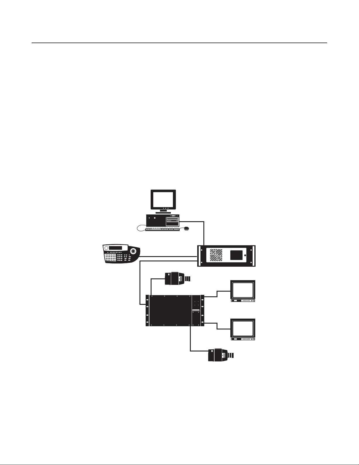
System Overview
This section provides an overview of the System 9760
The following information is provided:
• Description of the basic components of the 9760 system
• Summary listing of 9760 system device models and compatible equipment
DESCRIPTION
The 9760 system allows control and monitoring of up to 2,048 video input devices (for example, cameras) and 512 video output devices (for
example, monitors). The 9760 system consists of the following basic components (refer to Figure 1):
• CM9700-CC1 central processing unit (CPU): Controls system operation and therefore is also commonly referred to as the controller.
Connects to a wide variety of peripheral equipment. Detailed information about the CM9700-CC1 is provided in this manual.
• CM9760-MXB matrix bay: Performs all video switching functions as directed from the CM9700-CC1. Connects to a maximum of 256 video
input devices and 16 video output devices. Detailed information about the CM9760-MXB is provided in this manual.
• CM9760-KBD keyboard: Provides the user interface to system operations. Detailed information about the CM9760-KBD is provided in the
CM9760-KBD/KBR Keyboard Installation/Operation manual.
• CM9700-MGR system management software: Allows easy system setup and configuration and therefore is also commonly referred to as
the System Manager. Requires installation on a PC that meets CM9700-MGR system requirements. Detailed information about the
CM9700-MGR software and PC system requirements is provided in the CM9700-MGR Software Guide.
®
video matrix switching control system, hereinafter referred to simply as the 9760 system.
CM9700-MGR
CM9760-KBD
CAMERA 1
CM9760-MXB
CM9700-CC1
MONITOR 1
MONITOR 16
CAMERA 256
Figure 1. Basic Components of a 9760 System
NOTE: If your 9760 system includes a CM9760-CC1 that is running version 8.03.xxx or earlier software and you are using CM9760-MGR
software, refer to the CM9760-CC1 and CM9760-MGR documentation provided with your system.
In addition to the basic components, you can also use peripheral devices in the 9760 system. Peripheral devices include equipment such as
KBD300A/KBD200A keyboards, CM9760-MDA master distribution amplifiers, CM9760-ALM alarm interface units, CM9760-REL relay interface
units, Genex
®
multiplexers, and Pelco
®
VCRs.
C1572M (9/05) 9
Page 10

Note the following:
• To ensure uninterrupted operation, the 9760 system can be equipped with a backup CM9700-CC1 by means of a CM9760-HS hot switch.
• The CM9700-NW1, commonly referred to as the network interface unit (NIU), can be used to connect two or more CM9700-CC1 units to
• You can increase video output capacity of a single node from 128 to a maximum of 512 by using CM9760-MDA units. For detailed
MODELS
The following provides a list of models of 9760 system devices and compatible equipment.
CPU CONTROLLER AND COMPONENTS
CM9700-CC1 CPU controller. Operates on 120 VAC, 60 Hz or 230 VAC, 50 Hz.
CM9700-SER Serial communication (SERCOM) card (RS-422). Provides 8 SERCOM ports to interface peripheral equipment (4 cards
CM9700-SER-32 Port expansion unit. Provides 32 SERCOM ports. Includes interconnecting cables and adapters for DB9 and RJ-45
MATRIX BAY AND COMPONENTS
CM9760-MXB Video matrix bay equipped with CM9760-MPS power supply. Operates on 120 VAC, 60 Hz.
CM9760-MXB-X Same as CM9760-MXB except operates on 230 VAC, 50 Hz.
CM9760-MXBL Video matrix bay for use with CM9760-DFL downframe looping cards. No power required.
CM9760-MPS Matrix bay power supply (spare). Operates on 120 VAC, 60 Hz.
CM9760-MPS-X Matrix bay power supply (spare). Operates on 230 VAC, 50 Hz.
CM9760-RPC Rear panel input card. Provides 16 BNC connectors to connect video inputs to matrix bay.
CM9760-RPL Double-wide rear panel card for single-bay looping. Reduces maximum number of inputs to 128.
CM9760-DFC Downframe rear panel card and cable assembly. Connects multiple matrix bays for expansion purposes.
CM9760-DFL Downframe rear panel card and cable assembly with BNC connectors for looping video.
CM9760-VCC Video input card capable of accepting up to 16 video inputs. Also requires a rear panel card (CM9760-DFC,
CM9760-RPM Rear panel output card. Provides 16 BNCs to connect video outputs to matrix bay. Also interfaces video output
CM9760-VMC4 Video output card providing 4 video outputs. Requires CM9760-RPM.
CM9760-VMC8 Video output card providing 8 video outputs. Requires CM9760-RPM.
CM9760-VMC12 Video output card providing 12 video outputs. Requires CM9760-RPM.
CM9760-VMC16 Video output card providing 16 video outputs. Requires CM9760-RPM.
CM9760-VMM Video output module. Expands outputs of CM9760-VMC4, CM9760-VMC8, and CM9760-VMC12 video output cards.
For detailed information about the CM9760-HS, refer to the CM9760-HS Hot Switch Installation/Operation manual.
create a networked system. Each CM9700-CC1 unit and attached devices comprise a node in the network. For detailed information about
the CM9700-NW1, refer to the System 9760 Networking Guide.
information about the CM9760-MDA, refer to the CM9760-MDA Master Distribution Amplifier Installation/Operation manual.
maximum per CM9700-CC1).
connectors. Data interface can be RS-232 or RS-422. Up to 3 units can be added to a CM9700-CC1. (Check with Pelco
Systems Applications Department before adding to an existing CM9700-CC1.)
CM9760-DFL, or CM9760-RPC, or CM9760-RPL).
signals from CM9760-VMC4, CM9760-VMC8, CM9760-VMC12, or CM9760-VMC16 video output card.
KEYBOARDS
CM9760-KBD* Full-function desktop variable-speed keyboard. Operates on 120 VAC, 60 Hz.
CM9760-KBD-X* Same as CM9760-KBD except operates on 230 VAC, 50 Hz.
CM9760-KBR* Full-function 19-inch EIA rack mount keyboard. Operates on 120 VAC, 60 Hz.
CM9760-KBR-X* Same as CM9760-KBR except operates on 230 VAC, 50 Hz.
KBD300A Desktop keyboard with full switching capabilities plus joystick control of PTZ functions. Operates on 12 VAC or
±12 VDC. (Requires KBDKIT for power.)
KBD200A Desktop keyboard with full switching capabilities plus push-button control of PTZ functions. Operates on 12 VAC or
±12 VDC. (Requires KBDKIT for power.)
*Software version 8.03 or higher is required.
10 C1572M (9/05)
Page 11

NETWORK INTERFACE UNIT
CM9700-NW1 Network CPU and software necessary for joining two or more independent systems together. Allows multiple
systems to share video and control. Commonly referred to as the network interface unit (NIU).
OPTIONAL COMPONENTS
CM9760-ALM Alarm interface unit. Connects directly to each system. Each unit can monitor up to 64 alarms. Up to four units can be
connected in a series from one SERCOM port.
CM9760-CDU-T Code distribution unit. Sixteen-channel RS-422 transmit-only (two data wires and ground) distributor. Primarily used
for wiring up to 16 pan/tilt/zoom receivers in a “star” configuration.
CM9760-CXTA Coaxitron
16 receivers.
CM9760-DMR Data merger and port expander unit. Allows multiple CM9700-CC1 units to control multiple pan/tilt/zoom cameras
and allows multiple keyboards to communicate through one CM9700-CC1 port.
CM9760-DMR-X Same as CM9760-DMR except operates on 230 VAC, 50 Hz.
CM9760-HS Hot switch interface unit. Changeover unit that monitors the status of a primary CM9700-CC1 in the system.
CM9760-MDA Master distribution amplifier. Inserts master time and date from the CM9700-CC1 and a programmable title of up to
24 characters on 1 to 16 video signals.
CM9760-MDA-X Same as CM9760-MDA except operates on 230 VAC, 50 Hz.
CM9760-REL Relay interface unit. Connects directly to each system and provides dry contact switching for direct or automatic
control of peripheral equipment. Each unit provides up to 64 SPST contact outputs.
CM9760-VCRC Series VCR controllers capable of controlling 64 VCRs.
Genex Multiplexers Genex Series MX4009 (9-channel) and MX4016 (16-channel) multiplexers.
VMX200 and Video management systems. Graphical map/icon-based user interface for mouse-driven operator control from
VMX300 Series external PC.
®
translator. Generates Coaxitron signals for Pelco Coaxitron receivers. Each translator supports up to
COMPATIBLE RECEIVERS
®
Spectra
ERD97P21-U Pelco P-protocol receiver.
LRD41C21-1/-2/-3 Legacy
LRD41C22-1/-2/-3 Same as LRD41C21 Series except variable speed receiver.
Esprit
ExSite
Coaxitron Coaxitron translator allows Coaxitron control of PTZ cameras.
Series Spectra dome multiple protocol receiver.
®
fixed speed receiver with presets.
®
™
Integrated pan/tilt positioning receiver.
Integrated pan/tilt explosionproof positioning receiver.
C1572M (9/05) 11
Page 12

System Setup
This section provides information about the following:
• Overview of tasks necessary to set up a 9760 system
• Unpacking the CM9700-CC1 controller and CM9760-MXB matrix bay
• Installing the CM9700-CC1 controller
• Installing CM9760-MXB matrix bay(s)
• Verifying system operation
SYSTEM SETUP OVERVIEW
The following provides an overview of the tasks necessary to set up a 9760 system and prepare the system for operation. It is recommended that
you perform the tasks in the order listed below.
NOTE: For detailed instructions to perform the tasks listed below for setup of the CM9700-CC1 and CM9760-MXB, refer to the Unpacking,
Installing the CM9700-CC1 Controller, and Installing CM9760-MXB Matrix Bay(s) sections in this manual. For detailed instructions to perform the
tasks listed below for setup of all other devices in your system, refer to the manual provided for the device.
1. Unpack all equipment. Verify delivery according to the packing slip. Keep all manuals and cables with the associated equipment.
2. Select a location within a standard 19-inch (48.26 cm) EIA rack for each device to be mounted.
3. Mount each device into the selected location within a rack.
DANGER: When mounting equipment into a rack, always install equipment starting from the bottom of the rack. Installing equipment
starting from the top of the rack can cause the rack to topple.
4. Verify that the correct number of cards and power supplies have been installed in each CM9760-MXB in the system according to the system
order.
5. Install the CM9700-MGR software on a PC, and then do the following:
a. Copy the startconfig.psm file from the CM9700 Factory Configuration Data CD.
b. Open the startconfig.psm file using the CM9700-MGR.
NOTES:
• The CM9700-MGR software is contained on the CM9700 Resource CD, which is provided in the System 9760 binder. For CM9700-MGR
software installation instructions, refer to the CM9700-MGR Software Guide, which is also provided in the System 9760 binder.
• The CM9700 Factory Configuration Data CD is provided in the System 9760 binder.
• Do not modify the system using the CM9700-MGR until after you have verified system operation in step 12 below.
6. Connect all system devices to the CM9700-CC1 according to the CM9700-CC1 port assignments listed in the System 9760 port assignment
table.
NOTE: The System 9760 port assignment table, titled “System 9760 Factory Default Port Settings,” is provided in the System 9760 binder.
Detailed information about the System 9760 port assignment table is provided in the Installing the CM9700-CC1 Controller section in this
manual.
7. Connect power cabling to all devices.
8. Power on all devices connected to the CM9700-CC1.
9. Power on the CM9700-CC1.
10. Check diagnostic LEDs on devices to ensure that the devices are operating properly.
11. Connect all other cabling—for example, video input and output cabling—to all devices as appropriate.
12. Verify system operation (refer to the Verifying System Operation section in this manual).
12 C1572M (9/05)
Page 13

UNPACKING
Various items are supplied with the CM9700-CC1 and with the CM9760-MXB. Refer to the Unpacking the CM9700-CC1 and Unpacking the
CM9760-MXB sections for a list of items supplied with the units.
UNPACKING THE CM9700-CC1
The following items are supplied with the CM9700-CC1:
1 CM9700-CC1 unit, with front rack ears installed
1 120 VAC, 60 Hz power cord (USA standard)
1 230 VAC, 50 Hz power cord (European standard)
1 Keyboard, PS/2
1 PS/2-to-AT keyboard adapter
1 BNC extraction tool
2 Brackets with a set of 6 screws, 8-32 x 0.250-inch, pan head
2 Adjustable support rail sets (each set includes 1 front-mounting rail and 1 rear-mounting rail) and the following sets of screws:
6 Screws, 8-32 x 0.375-inch, pan head with washers
12 Screws, 10-32 x 0.375-inch, flat head
4 Screws, 10-32 x 0.750-inch, Phillips, pan head with washers
6 Screws, 8-32 x 0.250-inch, Phillips, pan head
UNPACKING THE CM9760-MXB
The following items are supplied with the CM9760-MXB:
1 CM9760-MXB matrix bay, with front rack ears installed
1 Power cord:
– For the CM9760-MXB: 120 VAC, 60 Hz power cord (USA standard)
– For the CM9760-MXB-X: 230 VAC, 50 Hz power cord (European standard)
NOTE: If the matrix bay is shipped with two power supplies installed, then two 120 VAC or 230 VAC power cords are supplied.
1 RJ-45 reversed data cable
8 Screws and washers for mounting the bay
1 Sheet of video input number labels that can be affixed to the rear panel BNC cards to correspond to video input numbers
In addition, one CM9760-VMC video output card, the appropriate number of CM9760-VCC video input cards, associated rear panel cards, and up
to two power supplies are installed in the matrix bay according to your system order.
C1572M (9/05) 13
Page 14

INSTALLING THE CM9700-CC1 CONTROLLER
Installation of the CM9700-CC1 includes the following tasks:
• Selecting a location for the CM9700-CC1 in a standard EIA rack
• Mounting the CM9700-CC1
• Connecting the CM9700-CC1
• Powering on the CM9700-CC1
To perform each of the above tasks, refer to the sections that follow.
SELECTING A LOCATION FOR THE CM9700-CC1
The CM9700-CC1 is designed to be mounted into a standard 19-inch (48.26 cm) EIA rack. When selecting a location in a rack for the
CM9700-CC1, note the following:
• The CM9700-CC1 occupies 4 RUs or 7 inches (17.78 cm) of vertical rack space.
• The maximum distance allowable between the CM9700-CC1 and a CM9760-MXB is 4,000 feet (1,219 meters).
• Allow at least 1 RU or 1.75 inches (4.5 cm) of space above the CM9700-CC1 for air circulation.
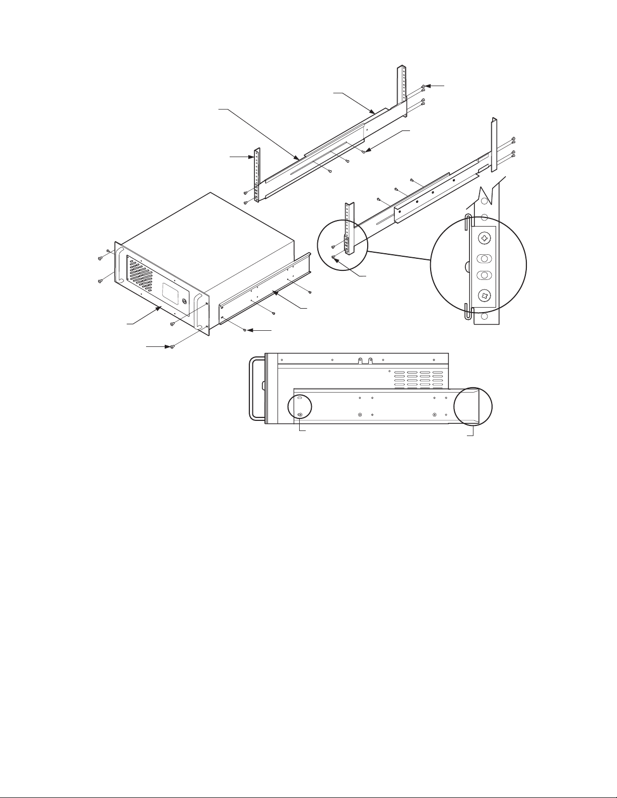
MOUNTING THE CM9700-CC1
Brackets and support rails are provided to mount the CM9700-CC1 into a rack. The brackets and support rails are provided for your convenience
but are not required.
To mount the CM9700-CC1 without the brackets and support rails, fasten each rack ear of the CM9700-CC1 to the rack using two 10-32 x
0.750-inch Phillips pan head screws and washers for each ear.
To mount the CM9700-CC1 using the supplied brackets and support rails, refer to Figure 2 and perform the following steps:
1. Attach one bracket to each side of the CM9700-CC1 using three 8-32 x 0.250-inch pan head screws for each side. Attach each bracket so
that the slotted holes in the bracket are positioned toward the front of the CM9700-CC1 and the tapered ends of the bracket are positioned
toward the rear of the CM9700-CC1.
2. For each set of support rails, attach the front-mounting support rail to the rear-mounting support rail using three 8-32 x 0.375-inch pan head
screws and washers for each set. Leave the screws loose until the support rails are attached to the rack.
3. Attach one set of support rails to the equipment rack in the desired location as follows:
a. Position the ear of the front-mounting support rail against the front of the equipment rack and align the holes in the ear of the rail
with the threaded holes in the rack. Attach the ear of the rail to the rack using two 10-32 x 0.375-inch flat head screws.
b. Adjust the support rails to the correct depth of the equipment rack by sliding the rear-mounting support rail to the back of the
equipment rack.
c. Attach the ear of the rear-mounting support rail to the rear of the equipment rack using four 10-32 x 0.375-inch flat head screws.
(The holes in the ear of the rail should align with the threaded holes in the equipment rack.)
4. Tighten the three 8-32 x 0.375-inch pan head screws and washers that were attached to the front- and rear-mounting support rails in step 2
above.
5. Repeat steps 3 and 4 for the second set of support rails.
6. Place the CM9700-CC1 onto the support rails and slide the unit into the rack. The CM9700-CC1 should slide in and out of the rack easily.
DANGER: When sliding the CM9700-CC1 out of the rack, be careful not to let the unit fall out of the rack.
7. Fasten each rack ear of the CM9700-CC1 to the equipment rack using two 10-32 x 0.750-inch Phillips pan head screws and washers for
each ear.
14 C1572M (9/05)
Page 15
CM9700-CC1
(4) SCREWS,
10-32 X 0.750-INCH
PHILLIPS, PAN HEAD
WITH WASHERS
FRONT MOUNTING
SUPPORT RAIL
RACK
REAR MOUNTING
SUPPORT RAIL
BRACKET
(SIDE VIEW)
(6) SCREWS, 8-32 X 0.250-INCH
PAN HEAD (3 EACH SIDE)
(6) SCREWS,
8-32 X 0.375-INCH
PAN HEAD WITH
WASHERS
(4) SCREWS
10-32 X 0.375-INCH
FLAT HEAD
(8) SCREWS,
10-32 X 0.375-INCH
FLAT HEAD
SLOTTED HOLES
TOWARDS FRONT
OF UNIT
Figure 2. Mounting the CM9700-CC1
TAPERED ENDS
TOWARDS REAR
OF UNIT
C1572M (9/05) 15
Page 16
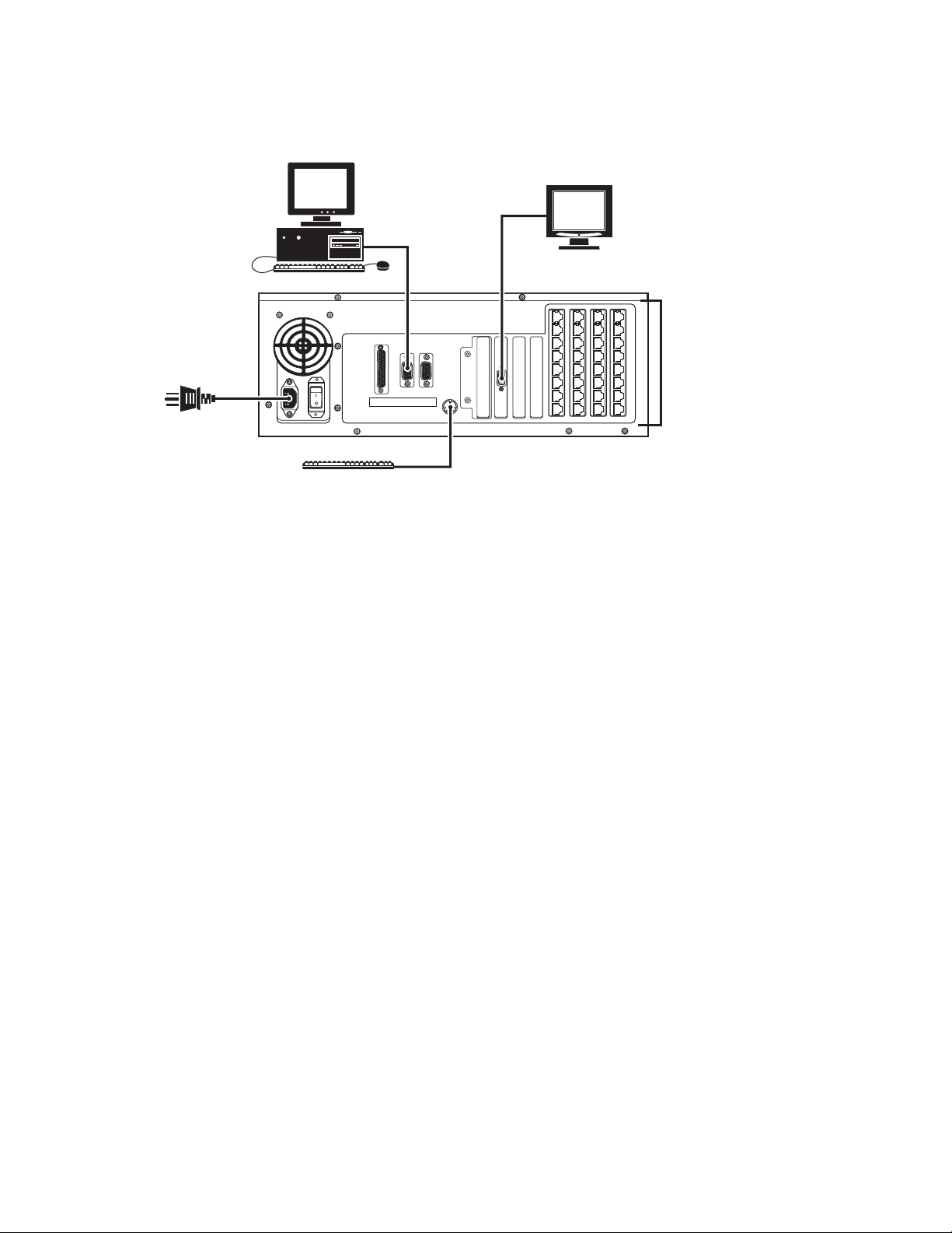
CONNECTING THE CM9700-CC1
System 9760 devices and other equipment connect to the rear panel of the CM9700-CC1 (refer to Figure 3).
CM9700-MGR PC
VGA MONITOR
CM9700-CC1
20
36
35
34
33
POWER CORD
COM1PRINTER COM2
PS/2 KEYBOARD
32
31
30
29
Figure 3. CM9700-CC1 Connections
As illustrated in Figure 3, CM9700-CC1 connections include the following:
• CM9700-MGR PC (RS-232 serial communication)
• VGA monitor
• PS/2 keyboard (supplied)
• System devices for RS-422 serial communication (for example, matrix bays, keyboards, and pan/tilt or dome receivers)
• Power cord (supplied)
12
28
11
19
27
10
18
26
9
17
25
24
16
8
15
23
7
14
22
6
5
1321
RS-422 SERCOM PORT
CONNECTIONS
For detailed information about each of the above connections, refer to the sections that follow.
NOTE: For detailed information about connecting ASCII communication devices to the CM9700-CC1, refer to Appendix A.
Connecting the CM9700-MGR PC to the CM9700-CC1
NOTES:
• It is recommended that you install the CM9700-MGR software on the PC before connecting the PC to the CM9700-CC1. For CM9700-MGR
software installation instructions, refer to the CM9700-MGR Software Guide.
• If your system is a networked system containing a CM9700-NW1 network interface unit, the CM9700-MGR PC connects to the
CM9700-NW1 rather than to a CM9700-CC1.
To connect the CM9700-MGR PC to the CM9700-CC1, refer to Figure 3 and do the following:
1. Using a null modem cable (not provided), connect one end of the cable to the COM 1 or COM 2 DB9 port on the CM9700-MGR PC.
2. Connect the other end of the cable to the COM1 DB9 port on the CM9700-CC1.
NOTE: Either COM 1 or COM 2 on the CM9700-CC1 can be used for connection to the CM9700-MGR PC. COM 1 is configured at the factory
for use with the CM9700-MGR PC and RS-232 communication.
Refer to Figure 4 for a diagram of null modem cable wiring connections.
16 C1572M (9/05)
Page 17
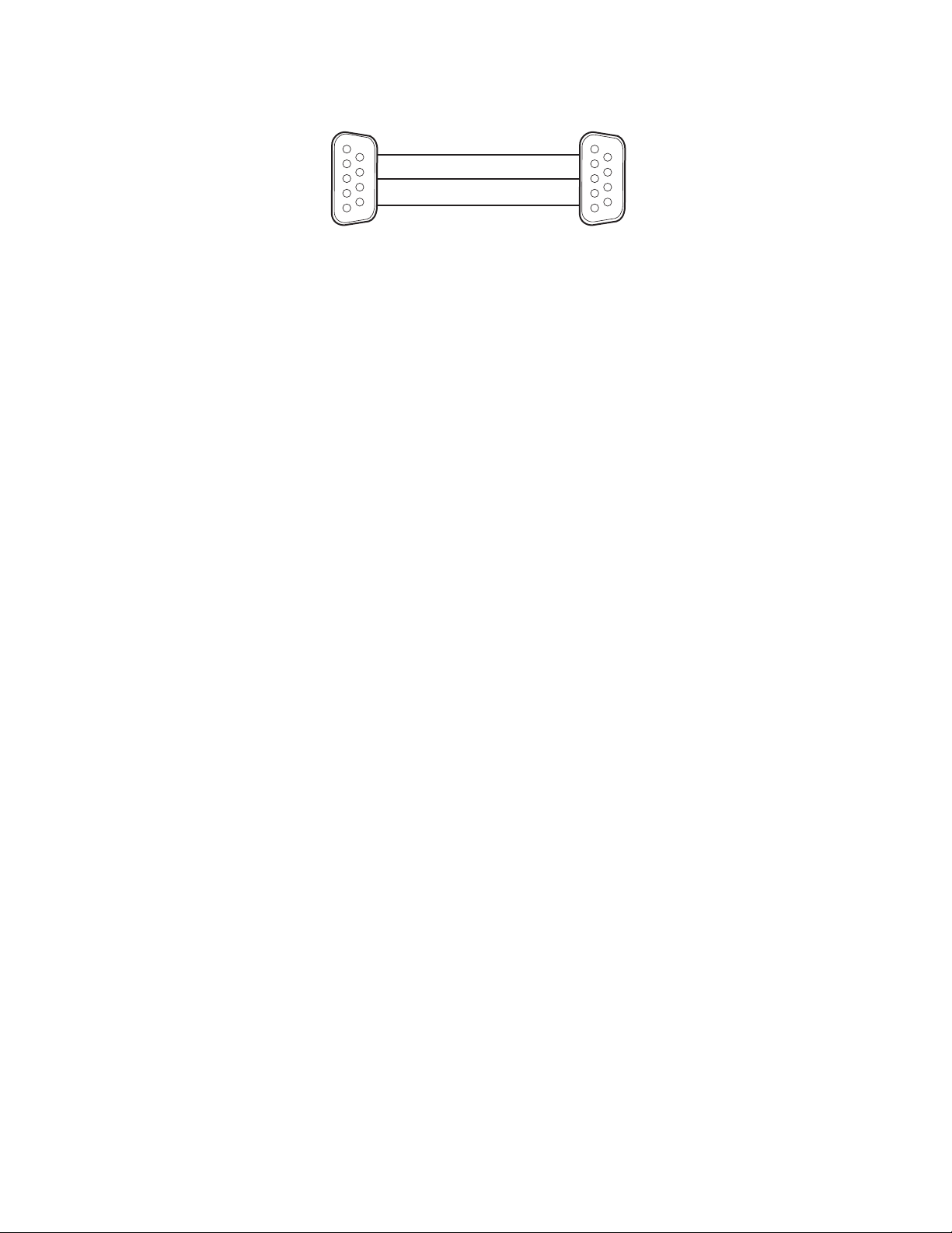
TO CM9700-MGR
PC COM 1/COM 2 PORT
TO CM9700-CC1
COM 1/COM 2 PORT
PIN 3 (TX)
PIN 2 (RX)
PIN 5 (GND)
NULL MODEM CABLE (RS-232)
DB9 FEMALE
PIN 2 (RX)
PIN 3 (TX)
PIN 5 (GND)
DB9 FEMALE
Figure 4. CM9700-MGR PC to CM9700-CC1 Null Modem Cable Connections
Connecting a VGA Monitor to the CM9700-CC1
When connected to the CM9700-CC1, a VGA monitor displays the CM9700-CC1 diagnostic screen (refer to Monitoring CM9700-CC1 Functions in
the System Diagnostics section for detailed information about the CM9700-CC1 diagnostic screen).
Connect a VGA monitor to the VGA port of the CM9700-CC1 (refer to Figure 3).
Connecting a PS/2 Keyboard to the CM9700-CC1
A PS/2 keyboard is supplied with the CM9700-CC1. To connect the keyboard to the CM9700-CC1, refer to Figure 3 and do the following:
1. Connect the supplied PS/2-to-AT keyboard adapter to the keyboard.
2. Connect the other end of the adapter to the AT-compatible keyboard port on the CM9700-CC1.
NOTE: An AT-compatible keyboard port also exists on the front of the CM9700-CC1 behind the front door. Both keyboard ports cannot be used at
the same time.
Connecting Devices to CM9700-CC1 RS-422 Serial Communication Ports
RS-422 serial communication ports 5-36, commonly referred to as SERCOM ports, are provided on the CM9700-CC1 for communication with
devices such as matrix bays, keyboards, and pan/tilt or dome receivers. Before connecting devices to the SERCOM ports, note the following:
• For a new system installation, refer to the System 9760 port assignment table titled “System 9760 Factory Default Port Settings” that is
provided in the System 9760 binder. The port assignment table lists the CM9700-CC1 ports and the particular device that should be
connected to each port as configured at the factory for your system. For additional information about the port assignment table, refer to the
Using the System 9760 Port Assignment Table section.
• Certain devices must be connected to SERCOM ports in a particular order based on device priority. In a new system installation that has
been configured at the factory, connecting devices according to the port assignments provided in the System 9760 port assignment table
ensures that you connect the correct device to the correct port.
If you add devices to an existing system, it is recommended that you configure your system using the CM9700-MGR software before
connecting devices to SERCOM ports. The CM9700-MGR software automatically assigns devices to SERCOM ports in the correct order.
By connecting devices according to the port assignments in CM9700-MGR, you ensure that you connect the correct device to the correct
port. For detailed information about SERCOM port device priorities, refer to the SERCOM Port Device Priority Connections section.
To connect a device to a SERCOM port, attach an RJ-45 data cable from the device to the appropriate SERCOM port. An RJ-45 data cable is
included with each 9760 system device for connection to the CM9700-CC1. For detailed information about connecting a matrix bay to the
CM9700-CC1, refer to the Installing CM9760-MXB Matrix Bay(s) section. For detailed information about connecting an ASCII communication
device to the CM9700-CC1, refer to Appendix A. For detailed information about connecting other devices to the CM9700-CC1, refer to the manual
supplied with the device.
NOTE: Shielded cabling is required to comply with CE emissions guidelines.
C1572M (9/05) 17
Page 18
Using the System 9760 Port Assignment Table
The System 9760 port assignment table, titled “System 9760 Factory Default Port Settings,” lists the CM9700-CC1 port numbers (1-36) and each
device that has been assigned to a particular CM9700-CC1 port and configured for your system at the factory. Figure 5 illustrates a sample port
assignment table for a system containing a CM9700-MGR (System Manager) PC, three CM9760-MXBs, and one CM9760-KBD. Note that the port
assignment table for your system will differ from the one shown in Figure 5 depending on the types and number of devices included in your
system.
System 9760 Factory Default Port Settings
12
20
28
36
11
19
27
35
10
18
26
34
9
17
25
33
8
16
24
32
7
15
23
31
6
14
22
PRINTER COM 1 COM2
30
5
13
21
29
Note:
The number of ports on your system may differ from the
above drawing. Connect System 9760 components as follows:
PORT
1(RS-232)
2(RS-232) 20
3
4
5
6
7
8
927
10 28
11 29
12 30
13 31
14 32
15 33
16 34
17 35
18 36
DESCRIPTION PORT DESCRIPTION
SYSTEM MANAGER
NOT AVAILABLE
NOT AVAILABLE
CM9760-MXB (2A) (OUTPUTS 1-16)
CM9760-MXB (2B) (OUTPUTS 17-32)
CM9760-MXB (2C) (OUTPUTS 33-48)
CM9760-KBD (PIN 1111)
19
23
24
25
26
Figure 5. Sample Port Assignment Table
18 C1572M (9/05)
Page 19
In the sample port assignment table shown in Figure 5, note the following:
• CM9700-CC1 port 1 (COM 1) is assigned and configured for the System Manager; therefore, the System Manager PC should be connected
to COM 1 on the CM9700-CC1.
NOTE: For all systems configured at the factory, COM 1 is always configured as the port to be used with the System Manager PC.
• CM9700-CC1 port 2 (COM 2) is not assigned or configured for any device.
• Because CM9700-CC1 ports 3 and 4 are not present on the CM9700-CC1, ports 3 and 4 are grayed out and are described as NOT
AVAILABLE.
• CM9700-CC1 port 5 is assigned and configured for the CM9760-MXB labeled 2A containing video outputs 1-16; therefore, the
CM9760-MXB labeled 2A should be connected to port 5 on the CM9700-CC1.
• CM9700-CC1 port 6 is assigned and configured for the CM9760-MXB labeled 2B containing video outputs 17-32; therefore, the
CM9760-MXB labeled 2B should be connected to port 6 on the CM9700-CC1.
• CM9700-CC1 port 7 is assigned and configured for the CM9760-MXB labeled 2C containing video outputs 33-48; therefore, the
CM9760-MXB labeled 2C should be connected to port 7 on the CM9700-CC1.
• CM9700-CC1 port 8 is assigned and configured for the CM9760-KBD having a pin number of 1111; therefore, the CM9760-KBD should be
connected to port 8 on the CM9700-CC1.
• Because no additional devices are included in the system, CM9700-CC1 ports 9-36 are not assigned or configured for any device.
SERCOM Port Device Priority Connections
The CM9760-HS hot switch, CM9700-NW1 network interface unit (required in a networked system), and CM9760-MXB matrix bays must be
connected to SERCOM ports in a particular order based on device priority. The CM9760-HS has the highest priority and, if present in the system,
always connects to SERCOM port 5. The CM9700-NW1 has the next highest priority if present in the system, followed by CM9760-MXBs. If
neither a CM9760-HS nor a CM9700-NW1 is present, then CM9760-MXBs have the highest priority and must be connected to the CM9700-CC1
starting at port 5. As a result, the order of connections depends on whether the system includes a CM9760-HS hot switch, a CM9700-NW1, or
both. Note that CM9760-MXBs must be connected in sequential order. After all CM9760-MXBs have been connected, all other devices—such as
keyboards—can then be connected in any order.
Table A, Table B, Table C, and Table D provide a list of the appropriate order of device connections to SERCOM ports in various types of systems.
The tables also include the device tree view portion of the CM9700-MGR Main window. The device tree identifies the appropriate port number
assigned to each device in the system.
Table A. RS-422 SERCOM Port Connections in a Single-Node System with a CM9760-HS Hot Switch
Device SERCOM Port Connection CM9700-MGR Device Tree Port Assignments
CM9760-HS Port 5
CM9760-MXB(s) Port 6 and next sequential ports as necessary—
connected through the hot switch
Other devices Any available ports connected through the hot
switch—connections do not have to be in
sequential ports
C1572M (9/05) 19
Page 20
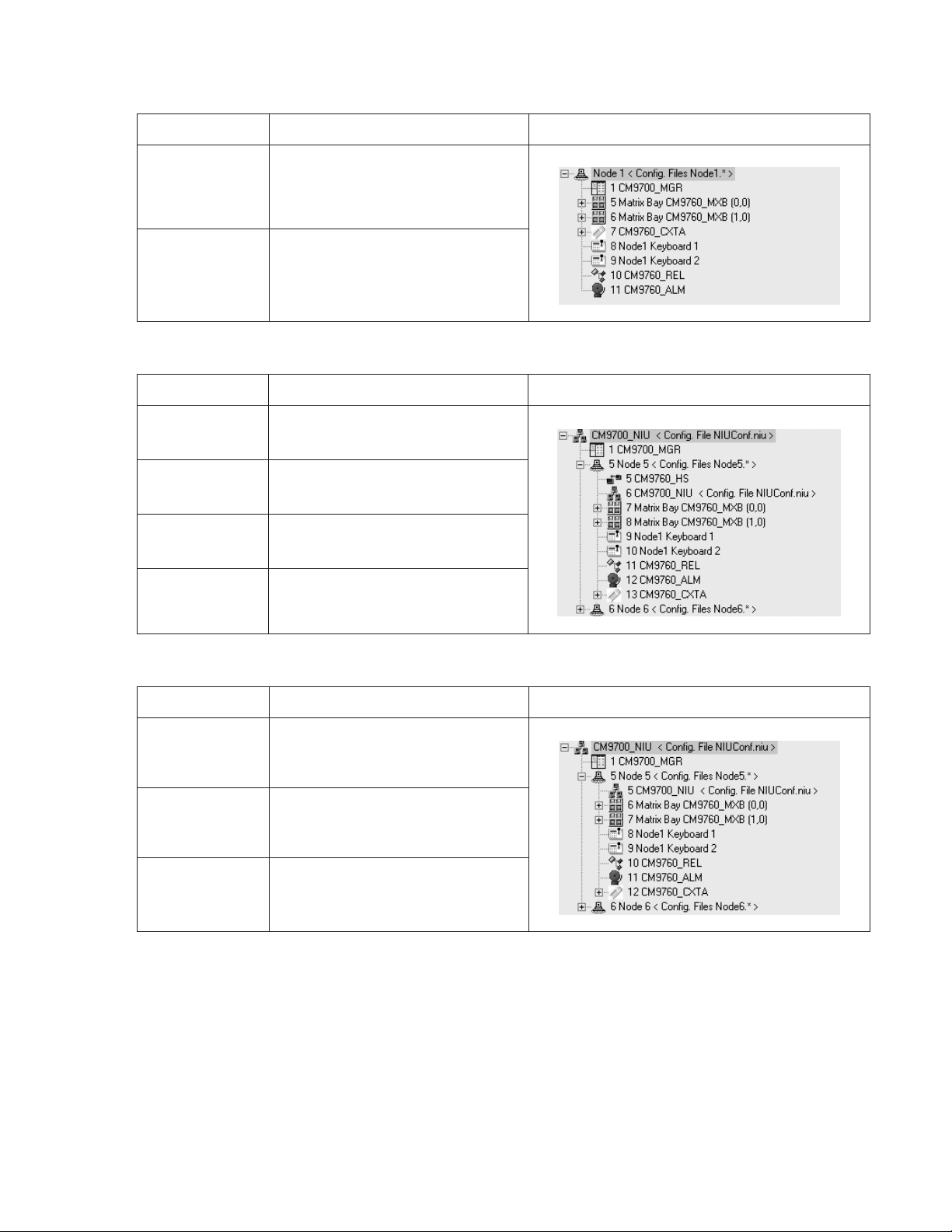
Table B. RS-422 SERCOM Port Connections in a Single-Node System without a CM9760-HS Hot Switch
Device SERCOM Port Connection CM9700-MGR Device Tree Port Assignments
CM9760-MXB(s) Port 5 and next sequential ports as necessary
Other devices Any available ports—connections do not have
to be in sequential ports
Table C. SERCOM Port Connections in a Networked System with a CM9760-HS Hot Switch
Device SERCOM Port Connection CM9700-MGR Device Tree Port Assignments
CM9760-HS Port 5
CM9700-NW1
network interface unit
Matrix bay(s) Port 7 and next sequential ports as necessary—
Other devices Any available ports connected through the hot
Device SERCOM Port Connection CM9700-MGR Device Tree Port Assignments
CM9700-NW1 network
interface unit
Matrix bay(s) Port 6 and next sequential ports as necessary
Other devices Any available ports—connections do not have
Port 6—connected through the hot switch
connected through the hot switch
switch—connections do not have to be in
sequential ports
Table D. SERCOM Port Connections in a Networked System without a CM9760-HS Hot Switch
Port 5 on each CM9700-CC1 in the network
to be in sequential ports
NOTE: If you add matrix bays to an existing system, you may need to change existing port connections to be able to connect each additional
matrix bay to the lowest sequential port possible.
Connecting Power to the CM9700-CC1
To connect power to the CM9700-CC1, connect the supplied 120 VAC or 230 VAC power cord to the power input receptacle on the CM9700-CC1
and to an approved power source.
NOTE: Do not power on the CM9700-CC1 until all system devices have been connected to the CM9700-CC1 and all system devices have been
powered on.
20 C1572M (9/05)
Page 21

POWERING ON THE CM9700-CC1
After all system devices have been connected to the CM9700-CC1 and all system devices have been powered on, power on the CM9700-CC1.
To power on the unit, place the power switch in the On (I) position. If, for some reason, you must power off the unit, place the power switch in the
Off (0) position.
INSTALLING CM9760-MXB MATRIX BAY(S)
Your System 9760 installation may include one or multiple CM9760-MXB matrix bays. Installation of a CM9760-MXB includes the following
tasks:
• Selecting a location for the CM9760-MXB in an EIA standard rack
• Mounting the CM9760-MXB
• Verifying CM9760-MXB component installation
• Connecting the CM9760-MXB to the CM9700-CC1
• Connecting power to the CM9760-MXB
• Powering on the CM9760-MXB
• Checking diagnostic LEDs
• Connecting video inputs and outputs
To perform each of the above tasks, refer to the sections that follow.
SELECTING A LOCATION FOR THE CM9760-MXB
The CM9760-MXB is designed to be mounted into a standard 19-inch (48.26 cm) EIA rack. When selecting a location in a rack for a
CM9760-MXB, note the following:
• The CM9760-MXB occupies 6 RUs or 10.5 inches (26.7 cm) of vertical rack space.
• Allow at least 1 RU or 1.75 inches (4.5 cm) of space above the CM9760-MXB for air circulation. In a high-temperature environment, it may
also be necessary to provide forced air cooling. Contact Product Support for additional information.
• The maximum distance allowable between a CM9760-MXB and the CM9700-CC1 is 4,000 feet (1,219 meters). Note that a 10-foot
(3.05 meters) reversed cable is supplied with the CM9760-MXB for connection to the CM9700-CC1. If you install a CM9760-MXB farther
than 10 feet from the CM9700-CC1, you must create your own cable.
In addition, if you are installing multiple matrix bays, note the following:
• When expanding video inputs beyond 256 as provided by a single matrix bay, the expansion of video inputs occurs in a horizontal manner
using a sideframing configuration. As a result, each additional matrix bay should be installed at the same level in a nearby rack.
When installing a new system containing multiple matrix bays to be sideframed, note that the rear of each matrix bay is labeled to identify
the location of each matrix bay in the sideframe configuration. For example, the matrix bays are labeled 2A, 12A, 22A, and so on.
• When expanding video outputs beyond 16 as provided by a single matrix bay, the expansion of video outputs occurs in a vertical manner
using a downframing configuration. As a result, multiple matrix bays must be installed in the same rack.
When installing a new system containing multiple matrix bays to be downframed, note that the rear of each matrix bay is labeled to
identify the location of each matrix bay in the downframe configuration. For example, the matrix bays are labeled 2A, 2B, 2C, and so on.
• When expanding video inputs beyond 256 and video outputs beyond 16, a combination of sideframing and downframing is used.
When installing a new system containing multiple matrix bays to be sideframed and downframed, note that the rear of each matrix bay is
labeled to identify the location of each matrix bay in the sideframe and downframe configuration. For example, matrix bays to be sideframed are labeled 2A, 12A, 22A, and so on; and matrix bays to be downframed are labeled 2B, 12B, 22B, and so on.
To help you determine the location of multiple matrix bays in your system, refer to Appendix B for sample illustrations of matrix bay
configurations. Note the labeling of the matrix bays shown in the sample illustrations. In addition, for detailed information about sideframing and
downframing, refer to Sideframing and Downframing in the CM9760-MXB Matrix Bay section.
C1572M (9/05) 21
Page 22
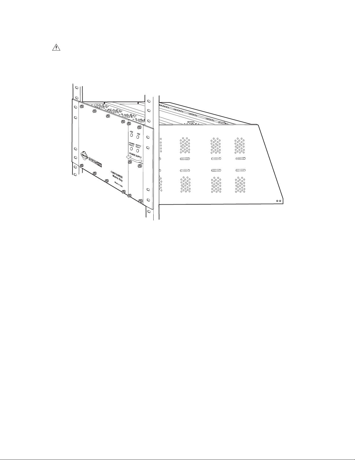
MOUNTING THE CM9760-MXB
DANGER: Always install equipment starting from the bottom of the rack. Installing equipment starting from the top of the rack can cause
the rack to topple.
To mount a CM9760-MXB into a rack, install the CM9760-MXB into the desired location and secure the unit using the supplied mounting
hardware (refer to Figure 6).
Figure 6. Mounting the CM9760-MXB
If you are mounting multiple matrix bays, note the following:
• If you are installing a new system, be sure to mount the matrix bays in a horizontal (sideframe) or vertical (downframe) manner according to
the bay location label provided on the rear of each matrix bay (refer to the Selecting a Location for the CM9760-MXB section for additional
information.)
• After mounting matrix bays in a downframe configuration, connect each supplied coaxial ribbon cable, referred to as a downframe cable, to
downframe connectors on rear panel cards as appropriate. The downframe cables are required to connect the video inputs from one matrix
bay to another. Figure 7 illustrates sample downframe cable connections between a CM9760-RPC card and a CM9760-DFC card and
between a CM9760-RPC card and a CM9760-DFL card in a configuration containing one downframed bay. For additional information, refer
to Downframing in the CM9760-MXB Matrix Bay section and to Appendix B.
22 C1572M (9/05)
Page 23
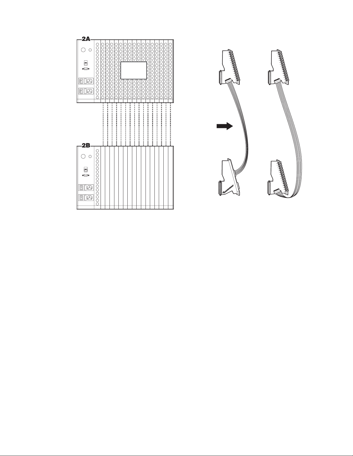
CM9760-MXB
BAY 1
Alarm
Black
Out
RS-422
RS-422
CAMS
1-256
RPC
RPC
SUPPLIED DOWNFRAMING CABLES
OR
16X RIBBON COAXIAL
CM9760-MXB
BAY 2
Alarm
Black
Out
RS-422
RS-422
DFC
DFL
Figure 7. Sample Downframe Cable Connections
VERIFYING CM9760-MXB COMPONENT INSTALLATION
Up to 16 CM9760-VCC video input cards, one CM9760-VMC video output card, and up to two power supplies are installed in a matrix bay at the
factory as ordered. Verify component installation as follows:
1. Remove the front panel of the matrix bay to view the video input and output cards.
2. Verify that the correct number of cards and power supplies are installed. In addition, verify that each installed card and power supply is
properly seated in the matrix bay.
Refer to the following sections for detailed information.
C1572M (9/05) 23
Page 24
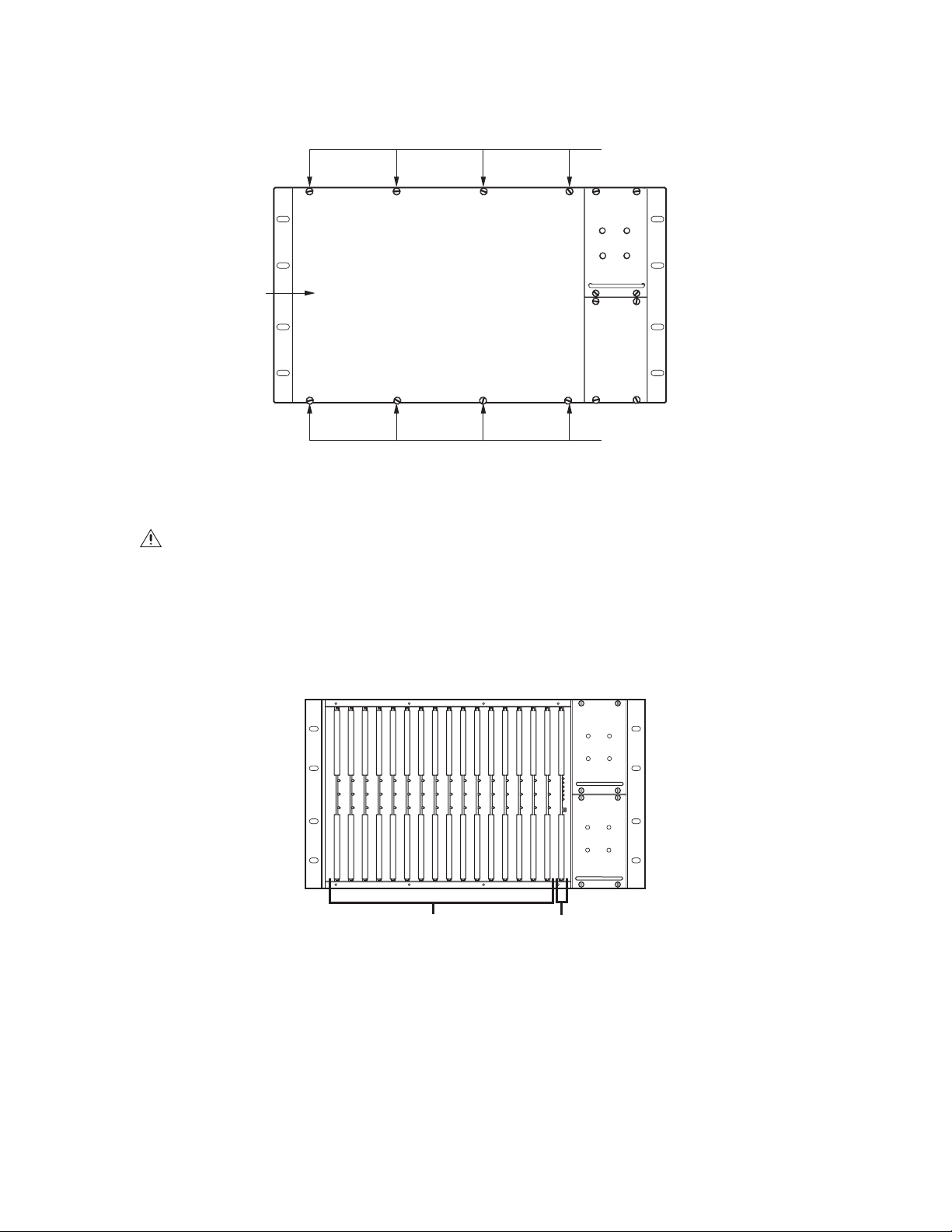
Removing the CM9760-MXB Front Panel
To remove the front panel of the CM9760-MXB, loosen the eight captive panel screws indicated in Figure 8.
CAPTIVE PANEL
SCREW (4)
FRONT
PAN EL
CAPTIVE PANEL
SCREW (4)
Figure 8. CM9760-MXB Front Panel
WARNING: Although the CM9760-MXB will function properly with the front panel removed, the front panel must be attached during
system operation to meet safety standards. To reattach the front panel, tighten the eight captive panel screws.
Verifying Input Card, Output Card, and Power Supply Installation
The CM9760-MXB accepts up to 16 CM9760-VCC video input cards in slots 1-16, one CM9760-VMC card in slot 17, and up to two power supplies
(refer to Figure 9). With the front panel removed, verify that the correct number of cards are installed as ordered and that they are firmly seated
in the appropriate slots. In addition, verify that the correct number of power supplies are installed as ordered and that each installed power
supply is firmly seated in the power supply slot.
-10V
+10V
FRAME
SUPPLY
FAULT
FAULT
-10V
+10V
FRAME
SUPPLY
FAULT
FAULT
CM9760-VCC
VIDEO INPUT
CARDS
(SLOTS 1-16)
Figure 9. Sample CM9760-MXB Configuration
NOTE: The configuration of your CM9760-MXB may differ from the configuration shown in Figure 9 depending on the number of video input
cards and power supplies ordered. If your configuration contains only one power supply, a blank plate covers the lower power supply slot.
CM9760-VMC
VIDEO OUTPUT
CARD
(SLOT 17)
24 C1572M (9/05)
Page 25
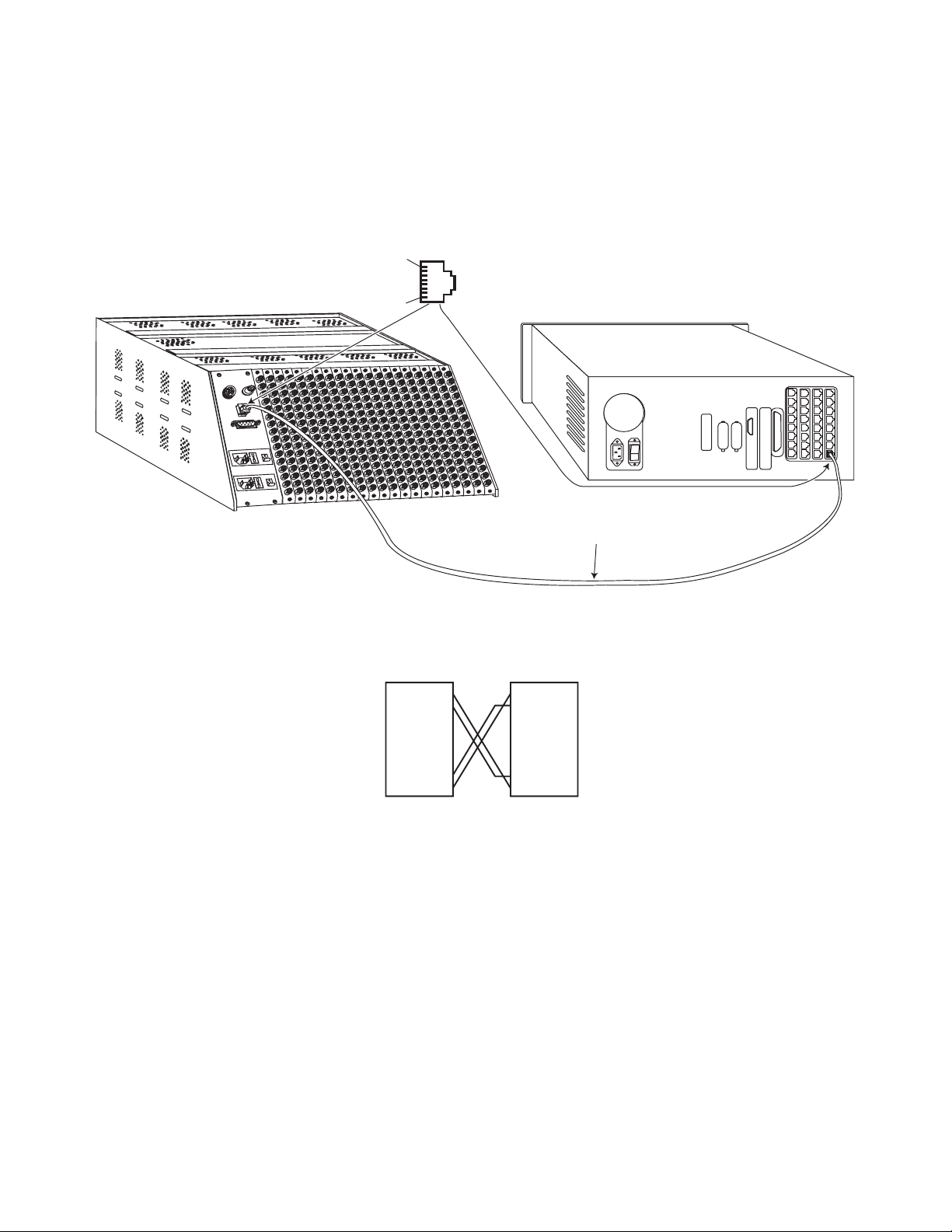
CONNECTING THE CM9760-MXB TO THE CM9700-CC1
Connect a CM9760-MXB to the CM9700-CC1 using the 10-foot (3.05 meters) reversed cable supplied with the CM9760-MXB. If you must create
a longer cable, it is recommended that you use a 24-gauge twisted pair cable.
As illustrated in Figure 10, connect the female RJ-45 serial communications data port labeled RS-422 on the rear of the CM9760-MXB to the
appropriate female RJ-45 serial communications port (RS-422) on the rear of the CM9700-CC1. Figure 10 provides an example of a CM9760-MXB
connected to port 5 on the CM9700-CC1.
8-PIN SERCOM PORT (FEMALE)
PIN 1=Tx+
PIN 2=Tx–
.
.
.
PIN 7=Rx–
PIN 8=Rx+
CM9700-CC1
REVERSED DATA CABLE (SUPPLIED)
CM9760-MXB (FULLY LOADED)
PIN 1
PIN 8
RS-422
DATA CABLE CONNECTIONS
CM9760-MXB CM9700-CC1
RJ-45 RJ-45
CONNECTOR CONNECTOR
PIN 1=Tx+
PIN 2=Tx–
.
.
.
.
PIN 7=Rx–
PIN 8=Rx+
PIN 1=Tx+
PIN 2=Tx–
.
.
.
.
PIN 7=Rx–
PIN 8=Rx+
Figure 10. CM9760-MXB to CM9700-CC1 Connection
C1572M (9/05) 25
Page 26
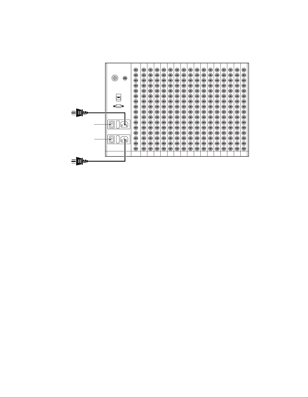
CONNECTING POWER TO THE CM9760-MXB
NOTE: A CM9760-MXB operates on 120 VAC, 60 Hz. A CM9760-MXB-X operates on 230 VAC, 50 Hz.
To connect power to a CM9760-MXB, plug the supplied power cord into the power input receptacle on the rear of the matrix bay for each power
supply installed (refer to Figure 11). Then plug the power cord for each installed power supply into an approved power source.
Alarm
Black
Out
RS-422
POWER CORD CONNECTION
TO UPPER POWER SUPPLY
POWER SWITCH FOR
UPPER POWER SUPPLY
POWER SWITCH FOR
LOWER POWER SUPPLY
POWER CORD CONNECTION
TO LOWER POWER SUPPLY
RS-422
Figure 11. CM9760-MXB Power Connections (Two Power Supplies Installed)
POWERING ON THE CM9760-MXB
NOTE: Do not power on the CM9760-MXB until after it is connected to the CM9700-CC1.
To power on a CM9760-MXB, place the corresponding power switch of each installed power supply in the On (I) position. If, for some reason, you
must power off the CM9760-MXB, place the corresponding power switch of each installed power supply in the Off (0) position.
CHECKING DIAGNOSTIC LEDS
Checking the diagnostic LEDs on a CM9760-MXB allows you to ensure that the unit is operating properly. It is recommended that you check the
LEDs on the CM9760-MXB before connecting video inputs and outputs to the unit.
With the CM9760-MXB powered on, check the LEDs as follows:
1. For each power supply installed, do the following:
a. Verify that the +10V and –10V power LEDs are lit (green).
If a power LED is not lit, ensure that the power supply is seated properly. If the condition persists, inspect the power supply fuse and
replace the fuse if necessary (refer to Replacing a Power Supply Fuse in the CM9760-MXB Component Installation or Replacement
section for detailed instructions).
b. Verify that the Frame Fault and the Supply Fault LEDs are not lit.
If the Frame Fault LED is lit (red), one or more video input/output cards has failed. Continue with step 2 for troubleshooting
information.
If the Supply Fault LED is lit (red), replace the power supply (refer to Replacing a Power Supply in the CM9760-MXB Component
Installation or Replacement section for detailed instructions).
26 C1572M (9/05)
Page 27
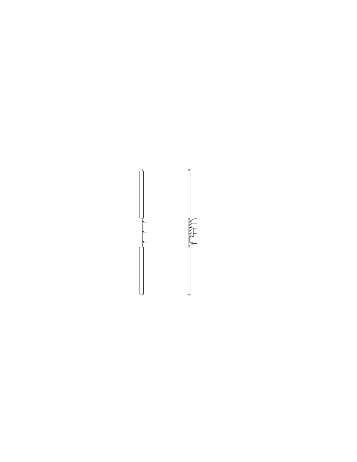
2. With the front panel of the CM9760-MXB removed, check the LEDs on the CM9760-VCC video input cards and on the CM9760-VMC video
output card as follows (refer to Figure 12):
a. Verify that all +10 VDC and –10 VDC power LEDs are lit (green).
If a power LED is not lit, remove the card and inspect the fuses (refer Figure 13 for fuse locations on CM9760-VCC and CM9760-VMC
cards). Replace fuse(s) if necessary. If the condition continues, replace the card. For instructions to replace a CM9760-VCC or
CM9760-VMC card, refer to Replacing a CM9760-VCC Card or to Replacing a CM9760-VMC Card in the CM9760-MXB Component
Installation or Replacement section as applicable.
b. Verify that all Comm Fail LEDs are not lit:
• If the LED is lit (red) on any video input card, reseat the card. If the condition continues, replace the card.
• If the Comm Fail LED is lit (red) on the video output card only, check the communication to the CM9700-CC1.
• If all Comm Fail LEDs are lit (red), press the Reset button located on the video output card (refer to Figure 12). If the problem
continues, replace the video output card.
For a summary of troubleshooting information relating to the CM9760-MXB, refer to Troubleshooting the CM9760-MXB in the Troubleshooting
section.
After you have verified that the CM9760-MXB is operating properly, reattach the front panel of the CM9760-MXB. Then connect video inputs and
outputs (refer to the Connecting Video Inputs and Video Outputs section).
COMM FAIL
+10 VDC
-10 VDC
CM9760-VCC
VIDEO INPUT CARD
CM9760-VMC
VIDEO OUTPUT CARD
COMM FAIL
+10 VDC
-10 VDC
NO ASSIGNMENT
RESET BUTTON
Figure 12. CM9760-VCC and CM9760-VMC Diagnostic LEDs
C1572M (9/05) 27
Page 28
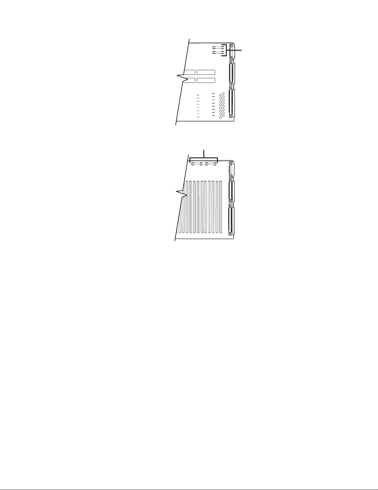
CM9760-VCC
VIDEO
INPUT
CARD
CM9760-VMC
VIDEO
OUTPUT
CARD
.7ASB FUSES
.7ASB FUSES
Figure 13. Fuse Locations on CM9760-VCC and CM9760-VMC Cards
28 C1572M (9/05)
Page 29
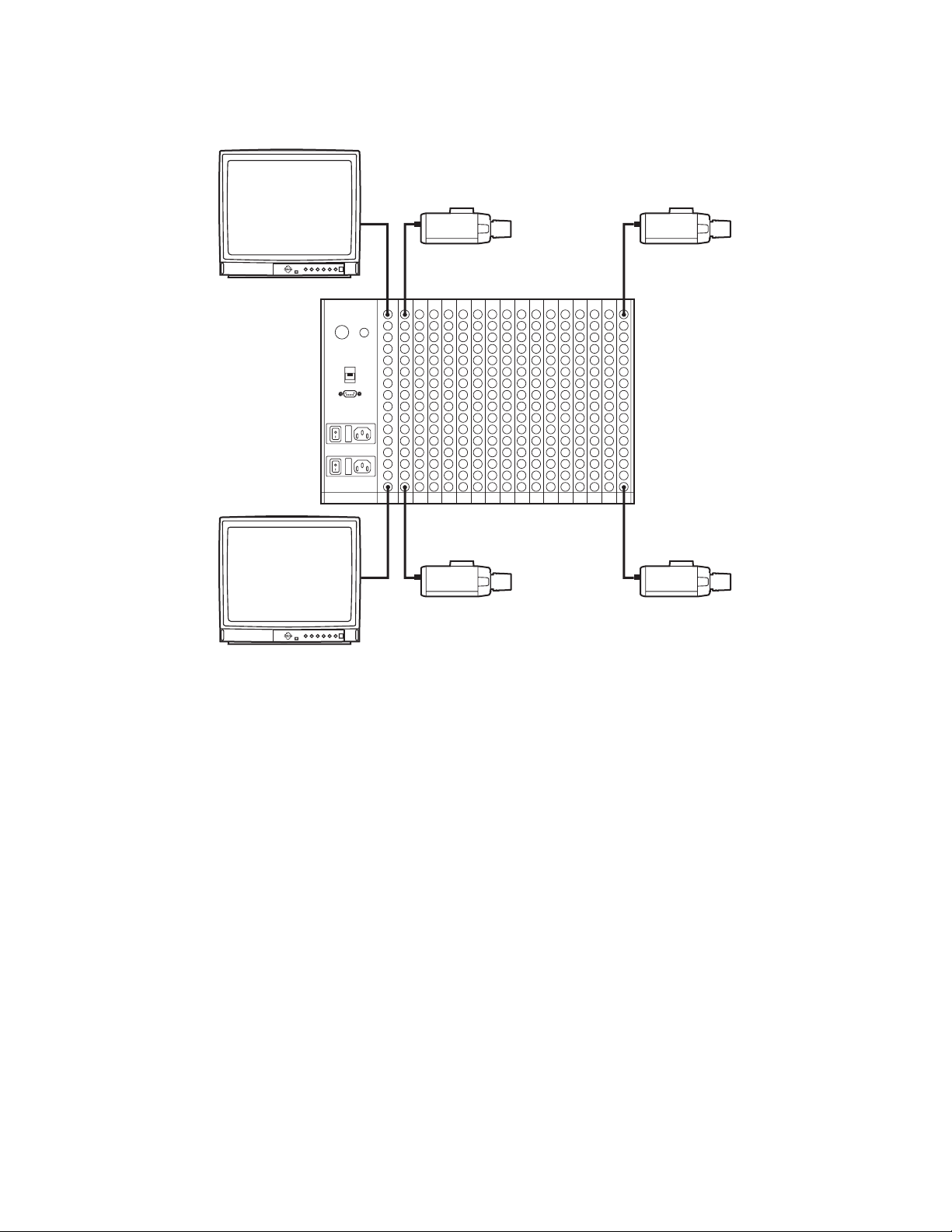
CONNECTING VIDEO INPUTS AND VIDEO OUTPUTS
Connect all video inputs (up to 256) and all video outputs (up to 16) to the rear panel BNC cards (refer to Figure 14).
1
241
Alarm
Black
Out
RS-422
RS-422
1
16
256
16
Figure 14. CM9760-MXB Video Input and Output Connections
Note the following:
• To provide adequate ground and signal connections, use crimp-on BNCs rather than screw-on BNCs.
• Allow enough slack in a cable to act as a strain relief between the cable and the BNC connectors.
• Be sure each connection is secure.
• Label all cabling to minimize system downtime if troubleshooting becomes necessary and cabling needs to be disconnected.
• Video output from the CM9760-VMC video output card is not terminated. Terminate the video signal at the output device (for example,
monitor,VCR, or matrix switcher). If you are looping to other devices, terminate the last device only.
• The endpoint of any video cable run must be teminated in 75 ohms.
• For information about sideframing video inputs and downframing video outputs, refer to Sideframing and Downframing in the
CM9760-MXB Matrix Bay section.
C1572M (9/05) 29
Page 30

VERIFYING SYSTEM OPERATION
After installation of the 9760 system is complete, verify system operation. To do so, perform the following from a CM9760-KBD:
1. Verify that the CM9760-KBD LCD displays the following:
SYSTEM 97XX
NOTE: Depending on the version of the CM9760-KBD software, the LCD displays SYSTEM 9760 or SYSTEM 9700.
2. Enter the default operator password on the CM9760-KBD keypad: The default password for operator 1 is 0101; the default password for
operator 2 is 0202; the default password for operator 3 is 0303, and so on. The passwords are defined in the Operator PIN field in
CM9700-MGR.
The LCD displays the following:
ENTER MONITOR #
3. Enter the number of the monitor you are viewing—for example, 1—and then press the MON key.
4. Enter a camera number, and then press the CAM key.
5. Press the FWD key to advance through cameras and verify switching.
For detailed information about 9760 system operation using the CM9760-KBD, refer to the CM9760-KBD/KBR Keyboard Installation/Operation
manual.
30 C1572M (9/05)
Page 31

CM9700-CC1 Component Installation or Replacement
WARNINGS:
• Installation or replacement of CM9700-CC1 components should be performed by qualified personnel only.
• Electrostatic discharge (ESD) precautions must be observed when installing or replacing CM9700-CC1 components. Always wear a
grounding strap connected to an approved grounding source when working on or near exposed electronic equipment.
This section provides information about the following:
• Removing the top cover of the CM9700-CC1 (the top cover must be removed before CM9700-CC1 components can be installed or
replaced)
• Installing or replacing a CM9700-SER card
For information about replacing the VGA card (CM9700-CC1-VID) in the CM9700-CC1, refer to the CM9700-CC1-VID VGA Video Card
Installation manual. For information about adding CM9700-SER-32 port expander units to the CM9700-CC1, refer to the CM9700-SER-32
Port Expander Installation/Operation manual.
REMOVING THE CM9700-CC1 TOP COVER
To remove the top cover of the CM9700-CC1, refer to Figure 15 and do the following:
1. Power off the CM9700-CC1.
WARNING: Failure to power off the CM9700-CC1 can result in serious damage to the equipment.
2. Remove the ten screws that hold the top cover in place.
3. Tilt the top cover up at a slight angle as indicated by the dotted line in Figure 15, and then pull the cover backwards to remove the cover
from the front edge of the CM9700-CC1 chassis.
Figure 15. CM9700-CC1 Top Cover Removal
C1572M (9/05) 31
Page 32

INSTALLING OR REPLACING A CM9700-SER CARD
WARNINGS:
• CM9700-SER card installation or replacement should be performed by qualified personnel only.
• Electrostatic discharge (ESD) precautions must be observed when installing or replacing a CM9700-SER card. Always wear a
grounding strap connected to an approved grounding source when working on or near exposed electronic equipment.
The CM9700-CC1 is shipped from the factory with a minimum of two CM9700-SER cards installed on the motherboard in ISA slots 1 and 2 (refer
to Figure 16). You can install additional CM9700-SER cards into ISA slots 3 and 4, totaling a maximum of four cards. You can also replace an
existing card. When installing or replacing a CM9700-SER card, you must set the interrupt and address jumpers on the new card.
CM9700-SER CARD
ACCESS SLOTS (SLOT
COVERS REMOVED)
ISA SLOTS (DEFAULT
CM9700-SER CARDS SUPPLIED IN
ISA SLOTS 1 AND 2)
CC1 CHASSIS, FRONT
Figure 16. CM9700-CC1 with Top Cover Removed
CC1 CHASSIS, REAR
To install or replace a CM9700-SER card, do the following:
1. Power off the CM9700-CC1.
WARNING: Failure to power off the CM9700-CC1 can result in serious damage to the equipment.
2. Remove the top cover of the CM9700-CC1 (refer to the Removing the CM9700-CC1 Top Cover section).
3. If replacing an existing CM9700-SER card, remove the card from the ISA slot.
4. On the new CM9700-SER card, set the W1 interrupt (IRQ) and W2 address select jumpers (refer to Figure 17 and to Table E). Note that the
jumper settings vary depending on the ISA slot into which the card is to be installed. If you are replacing a card, the jumper settings should
match the settings on the card being replaced.
32 C1572M (9/05)
Page 33

W1 IRQ SELECT
PIN 2
PIN 1
IRQ 3
IRQ 4
IRQ 5
IRQ 6
IRQ 7
IRQ 9
IRQ 10
IRQ 11
W2 ADDRESS
SELECT
PIN 2
PIN 1
PIN 4
PIN 3
Figure 17. Sample CM9700-SER Card Jumper Assignments
Table E. CM9700-SER Card Jumper Assignments
ISA Slot Number W1 IRQ Setting W2 Address Setting
1 IRQ 10 Pins 1 to 2 and 3 to 4
2 IRQ 11 Pins 1 to 2 only
IRQ 12
IRQ 14
PIN 22
PIN 21
IRQ 15
3 IRQ 12 Pins 3 to 4 only
4* IRQ 5 No jumpers
*The jumper assignments shown for ISA slot 4 are applicable to the CM9700-CC1 but are
not applicable to the CM9700-NW1. A maximum of three CM9700-SER cards can be
installed into the CM9700-NW1 (ISA slots 1, 2, and 3). The CM9700-NW1 is shipped from
the factory with a minimum of one CM9700-SER card installed into ISA slot 1.
5. Install the new CM9700-SER card into the desired slot.
6. Reattach the front cover of the CM9700-CC1.
7. Power on the CM9700-CC1.
Note the following:
• You can cycle through the IRQ/address settings by toggling the ALT+A key combination on the PC keyboard associated with the
CM9700-CC1 diagnostic screen. (For information about the CM9700-CC1 diagnostic screen, refer to the System Diagnostics section.)
• When connecting system devices to the serial communication ports of the CM9700-SER card, shielded cabling is required to comply with
CE emissions guidelines.
C1572M (9/05) 33
Page 34

CM9760-MXB Component Installation or Replacement
WARNINGS:
• Installation or replacement of CM9760-MXB components should be performed by qualified personnel only.
• Electrostatic discharge (ESD) precautions must be observed when installing or replacing CM9760-MXB components. Always wear a
grounding strap connected to an approved grounding source when working on or near exposed electronic equipment.
This section provides information about the following:
• Installing or replacing rear panel cards (CM9760-RPC, CM9760-RPL, CM9760-DFC, CM9760-DFL, and CM9760-RPM)
• Installing or replacing a CM9760-VCC video input card
• Installing or replacing a CM9760-VMC video output card
• Installing a CM9760-VMM module on a CM9760-VMC video output card
• Installing or replacing a power supply
• Replacing a power supply fuse
In addition, this section also provides information about enabling/disabling the power supply alarm.
INSTALLING OR REPLACING REAR PANEL CARDS
CM9760-RPC, CM9760-RPL, CM9760-DFC, CM9760-DFL, and CM9760-RPM cards are installed into the rear of the matrix bay. For an initial
system installation, the cards are installed at the factory as ordered. Rear panel cards (and associated front panel cards) can be added to expand
a system or can be replaced if necessary.
NOTE: Rear panel cards must be installed before the associated CM9760-VCC video input card or CM9760-VMC video output card is installed
into the front of the matrix bay.
INSTALLING OR REPLACING A CM9760-RPC REAR PANEL INPUT CARD
Up to 16 CM9760-RPC cards can be installed into 16 possible slot positions that are associated with the slot positions of the corresponding
CM9760-VCC cards to be installed. If necessary, a CM9760-RPC card can be replaced. To install or replace a CM9760-RPC card, refer to the
sections that follow.
Installing a CM9760-RPC Card
WARNINGS:
• Rear panel card installation should be performed by qualified personnel only.
• Electrostatic discharge (ESD) precautions must be observed when installing a rear panel card. Always wear a grounding strap
connected to an approved grounding source when working on or near exposed electronic equipment.
NOTE: A CM9760-RPC card must be installed before the associated CM9760-VCC video input card is installed.
To install a CM9760-RPC card, do the following:
1. Set termination jumpers JP1-JP16 (refer to Figure 18) in the proper position:
• In a single-bay configuration, the setting of the jumpers depends on whether video is to be looped to another device (for example, a
DVR, VCR, or matrix switcher):
– When looping is not required, set the jumpers in the terminated position (jumper positions 1 and 2) (default setting).
– When looping is required, set the jumpers in the unterminated position (jumper positions 2 and 3).
• In multiple-bay configurations, set the jumpers in the unterminated position.
2. Locate the desired slot position at the rear of the bay.
NOTE: The physical number of a video input is determined by the position of the CM9760-VCC card, which is installed into the front of the
matrix bay. Viewed from the rear of the matrix bay, slot 1 is located on the right and corresponds to physical input numbers 1-16, slot 2
corresponds to physical input numbers 17-32, and so on. As a result, if you do not install CM9760-RPC cards in sequential order, be sure to
use the correct physical input number when programming the system using the CM9700-MGR.
3. Remove the blank cover plate by loosening the screw at the top and bottom of the plate.
34 C1572M (9/05)
Page 35

4. Slide the new card into the card guides (refer to Figure 19).
5. Push the card into place firmly.
6. Tighten the screw at the top and bottom of the card.
7. Connect BNC and downframe cables as applicable.
TERMINATEDUNTERMINATED
JP1-JP16
Figure 18. Termination Jumpers on CM9760-RPC Rear Panel Input Card Figure 19. CM9760-RPC Rear Panel Input Card Installation
C1572M (9/05) 35
Page 36

Replacing a CM9760-RPC Card
WARNINGS:
• Rear panel card replacement should be performed by qualified personnel only.
• Electrostatic discharge (ESD) precautions must be observed when replacing a rear panel card. Always wear a grounding strap
connected to an approved grounding source when working on or near exposed electronic equipment.
NOTE: Before replacing a CM9760-RPC card, you must remove the front panel of the matrix bay and disconnect the associated CM9760-VCC
video input card from the connectors on the backplane and from the connector on the CM9760-RPC card that is to be replaced. To disconnect the
CM9760-VCC card, grasp the two card handles and firmly pull the card toward you until the card is disconnected (refer to the Installing or
Replacing a CM9760-VCC Video Input Card section for additional information).
To replace a CM9760-RPC card, do the following:
1. Ensure that the associated CM9760-VCC video input card is disconnected as noted above.
2. Disconnect BNC and downframe cables, as applicable, from the CM9760-RPC card being replaced.
3. Remove the CM9760-RPC card by loosening the screw at the top and bottom of the card and then pulling the card toward you until it is out
of the frame.
4. Install the new CM9760-RPC card (refer to the Installing a CM9760-RPC Card section). Note that you should set the termination jumpers on
the new card to match the jumper positions on the card being replaced.
After the CM9760-RPC card has been replaced, reconnect the associated CM9760-VCC card by sliding the card toward the rear of the matrix bay
until the card is seated firmly with the backplane connectors and the CM9760-RPC connector. Note that, unless the audible alarm on the power
supply has been disabled, the alarm beeps twice and the Frame Fault LED flashes red twice. Then reattach the front panel of the matrix bay.
36 C1572M (9/05)
Page 37

INSTALLING OR REPLACING A CM9760-RPL REAR PANEL LOOPING CARD
The CM9760-RPL rear panel looping card contains two rows of BNC connectors and therefore occupies two slot positions in the matrix bay.
The CM9760-RPL card connects to one CM9760-VCC video input card, which is installed into the front of the matrix bay. Up to eight CM9760-RPL
cards can be installed when a maximum of 128 video inputs is required in a system that also requires looping. If necessary, a CM9760-RPL card
can be replaced. To install or replace a CM9760-RPL card, refer to the sections that follow.
Installing a CM9760-RPL Card
WARNINGS:
• Rear panel card installation should be performed by qualified personnel only.
• Electrostatic discharge (ESD) precautions must be observed when installing a rear panel card. Always wear a grounding strap con-
nected to an approved grounding source when working on or near exposed electronic equipment.
NOTE: A CM9760-RPL card must be installed before the associated CM9760-VCC video input card is installed.
To install a CM9760-RPL card, do the following:
1. Set termination jumpers JP1-JP16 (refer to Figure 20) in the proper position:
• When looping functions are required, set the jumpers in the unterminated position (positions 2 and 3).
• When looping functions are not required, set the jumpers in the terminated position (positions 1 and 2).
UNTERMINATED
3
TERMINATED
1
2
JP1-JP16
Figure 20. Termination Jumpers on CM9760-RPL Card
2. Locate the desired slot position at the rear of the bay.
NOTE: In a bay that is to be fully populated with CM9760-RPL cards, each card must be installed into an odd slot position only.
The corresponding CM9760-VCC cards must also occupy odd slot positions.
C1572M (9/05) 37
Page 38

3. Remove the blank cover plate by loosening the screw at the top and bottom of the plate.
4. Slide the new card into the card guides (refer to Figure 21).
Figure 21. CM9760-RPL Rear Panel Looping Card Installation
5. Push the card into place firmly.
6. Tighten the two screws at the top and bottom of the card.
7. Connect BNC and downframe cables as applicable.
Replacing a CM9760-RPL Card
WARNINGS:
• Rear panel card replacement should be performed by qualified personnel only.
• Electrostatic discharge (ESD) precautions must be observed when replacing a rear panel card. Always wear a grounding strap
connected to an approved grounding source when working on or near exposed electronic equipment.
NOTE: Before replacing a CM9760-RPL card, you must remove the front panel of the matrix bay and disconnect the associated CM9760-VCC
video input card from the connectors on the backplane and from the connector on the CM9760-RPL card that is to be replaced. To disconnect the
CM9760-VCC card, grasp the two card handles and firmly pull the card toward you until the card is disconnected (refer to the Installing or
Replacing a CM9760-VCC Video Input Card section for additional information).
To replace a CM9760-RPL card, do the following:
1. Ensure that the associated CM9760-VCC video input card is disconnected as noted above.
2. Disconnect BNC and downframe cables, as applicable, from the CM9760-RPL card being replaced.
3. Remove the CM9760-RPL card by loosening the two screws at the top and bottom of the card and then pulling the card toward you until it
is out of the frame.
4. Install the new card (refer to the Installing a CM9760-RPL Card section). Note that you should set termination jumpers on the new card to
match the jumper positions on the card being replaced.
After the CM9760-RPL card has been replaced, reconnect the associated CM9760-VCC card by sliding the card toward the rear of the matrix bay
until the card is seated firmly with the backplane connectors and CM9760-RPL connector. Note that, unless the audible alarm on the power
supply has been disabled, the alarm beeps twice and the Frame Fault LED flashes red twice. Then reattach the front panel of the matrix bay.
38 C1572M (9/05)
Page 39

INSTALLING OR REPLACING A CM9760-DFC DOWNFRAME CARD
The CM9760-DFC card is installed in every bay between the first and last bays in a downframe configuration. The card can also be used in the
last bay if looping is not required. Up to 16 CM9760-DFC cards can be installed into 16 possible slot positions that are associated with the slot
positions of the corresponding CM9760-VCC cards to be installed. If necessary, a CM9760-DFC card can be replaced. To install or replace a
CM9760-DFC card, refer to the sections that follow.
Installing a CM9760-DFC Card
WARNINGS:
• Rear panel card installation should be performed by qualified personnel only.
• Electrostatic discharge (ESD) precautions must be observed when installing a rear panel card. Always wear a grounding strap
connected to an approved grounding source when working on or near exposed electronic equipment.
NOTE: A CM9760-DFC card must be installed before the associated CM9760-VCC video input card is installed.
To install a CM9760-DFC card, do the following:
1. Set termination jumpers JP1-JP16 (refer to Figure 22) in the proper position:
• When CM9760-DFC cards are to be installed in intermediate bays, set the jumpers in the unterminated position (jumper positions
2 and 3).
• When CM9760-DFC cards are to be installed in the last bay, set the jumpers in the terminated position (jumper positions 1 and 2).
UNTERMINATED
3
2
1
TERMINATED
JP
1
JP
16
Figure 22. Termination Jumpers on CM9760-DFC Downframe Card
2. Locate the desired slot position at the rear of the bay.
3. Remove the blank cover plate by loosening the screw at the top and bottom of the plate.
4. Slide the new card into the card guides (refer to Figure 23).
C1572M (9/05) 39
Page 40

Figure 23. CM9760-DFC Downframe Card Installation
5. Push the card into place firmly.
6. Tighten the screw at the top and bottom of the card.
7. Connect downframe cables as applicable.
Replacing a CM9760-DFC Card
WARNINGS:
• Rear panel card replacement should be performed by qualified personnel only.
• Electrostatic discharge (ESD) precautions must be observed when replacing a rear panel card. Always wear a grounding strap
connected to an approved grounding source when working on or near exposed electronic equipment.
NOTE: Before replacing a CM9760-DFC card, you must remove the front panel of the matrix bay and disconnect the associated CM9760-VCC
video input card from the connectors on the backplane and from the connector on the CM9760-DFC card that is to be replaced. To disconnect the
CM9760-VCC card, grasp the two card handles and firmly pull the card toward you until the card is disconnected (refer to the Installing or
Replacing a CM9760-VCC Video Input Card section for additional information).
To replace a CM9760-DFC card, do the following:
1. Ensure that the associated CM9760-VCC video input card is disconnected as noted above.
2. Disconnect downframe cables, as applicable, from the CM9760-DFC card being replaced.
3. Remove the CM9760-DFC card by loosening the screw at the top and bottom of the card and then pulling the card toward you until it is out
of the frame.
4. Install the new card (refer to the Installing a CM9760-DFC Card section). Note that when setting the termination jumpers on the new card,
the jumper positions should match the jumper positions on the card being replaced.
After the CM9760-DFC has been replaced, reconnect the associated CM9760-VCC card by sliding the card toward the rear of the matrix bay until
the card is seated firmly with the backplane connectors and CM9760-DFC connector. Note that, unless the audible alarm on the power supply has
been disabled, the alarm beeps twice and the Frame Fault LED flashes red twice. Then reattach the front panel of the matrix bay.
40 C1572M (9/05)
Page 41

INSTALLING OR REPLACING A CM9760-DFL DOWNFRAME LOOPING CARD
The CM9760-DFL downframe looping card is used in the last bay in a downframe configuration. Note the following:
• In a CM9760-MXB(-X), the CM9760-DFL card connects to a CM9760-VCC video input card, which is installed into the front of the matrix bay.
Up to 16 CM9760-DFL cards can be installed into 16 possible slot positions that are associated with the slot positions of the corresponding
CM9760-VCC cards to be installed.
• In a CM9760-MXBL, up to 16 CM9760-DFL cards can be installed into slot positions that correspond to the video input slot positions in the
bay above. In the CM9760-MXBL, the CM9760-DFL cards do not connect to CM9760-VCC cards.
If necessary, a CM9760-DFL card can be replaced. To install or replace a CM9760-DFL card, refer to the sections that follow.
Installing a CM9760-DFL Card
WARNINGS:
• Rear panel card installation should be performed by qualified personnel only.
• Electrostatic discharge (ESD) precautions must be observed when installing a rear panel card. Always wear a grounding strap
connected to an approved grounding source when working on or near exposed electronic equipment.
NOTE: When a CM9760-DFL card is to be connected to a CM9760-VCC video input card, the CM9760-DFL card must be installed before the
associated CM9760-VCC card is installed.
To install a CM9760-DFL card, do the following:
1. Set termination jumpers JP1-JP16 (refer to Figure 24) in the proper position:
• When looping to another device is required, set the jumpers in the unterminated position (jumper positions 2 and 3). Termination must
occur at the final device.
• When looping is not required, set the jumpers in the terminated position (jumper positions 1 and 2).
JP1-JP16
TERMINATEDUNTERMINATED
Figure 24. Termination Jumpers on CM9760-DFL Card
2. Locate the desired slot position at the rear of the bay.
3. Remove the blank cover plate by loosening the screw at the top and bottom of the plate.
C1572M (9/05) 41
Page 42

4. Slide the new card into the card guides (refer to Figure 25).
Figure 25. CM9760-DFL Downframe Looping Card Installation
5. Push the card into place firmly.
6. Tighten the screw at the top and bottom of the card.
7. Connect BNC and downframe cables as applicable.
Replacing a CM9760-DFL Card
WARNINGS:
• Rear panel card replacement should be performed by qualified personnel only.
• Electrostatic discharge (ESD) precautions must be observed when replacing a rear panel card. Always wear a grounding strap
connected to an approved grounding source when working on or near exposed electronic equipment.
NOTE: Before replacing a CM9760-DFL card in a CM9760-MXB(-X), you must remove the front panel of the matrix bay and disconnect the
associated CM9760-VCC video input card from the connectors on the backplane and from the connector on the CM9760-DFL card that is to be
replaced. To disconnect the CM9760-VCC card, grasp the two card handles and firmly pull the card toward you until the card is disconnected
(refer to the Installing or Replacing a CM9760-VCC Video Input Card section for additional information).
To replace a CM9760-DFL card, do the following:
1. CM9760-MXB(-X) only: Ensure that the associated CM9760-VCC video input card is disconnected as noted above.
2. Disconnect BNC and downframe cables, as applicable, from the CM9760-DFL card being replaced.
3. Remove the CM9760-DFL card by loosening the screw at the top and bottom of the card and then pulling the card toward you until it is out
of the frame.
4. Install the new card (refer to the Installing a CM9760-DFL Card section). Note that when setting the termination jumpers on the new card,
you should match the jumper positions on the card being replaced.
CM9760-MXB(-X) only: After the CM9760-DFL has been replaced, reconnect the associated CM9760-VCC card by sliding the card toward the rear
of the matrix bay until the card is seated firmly with the backplane connectors and CM9760-DFL connector. Note that, unless the audible alarm
on the power supply has been disabled, the alarm beeps twice and the Frame Fault LED flashes red twice. Then reattach the front panel of the
matrix bay.
42 C1572M (9/05)
Page 43

INSTALLING OR REPLACING A CM9760-RPM REAR PANEL OUTPUT CARD
Only one CM9760-RPM card can be installed into the rear of the matrix bay. The card must always be installed into the leftmost slot. From the
rear of the bay, the leftmost slot provides the connection point for the CM9760-VMC video output card, which is always installed into slot 17 in
the front of the bay. If necessary, a CM9760-RPM card can be replaced. To install or replace a CM9760-RPM card, refer to the sections that
follow.
Installing a CM9760-RPM Card
WARNINGS:
• Rear panel card installation should be performed by qualified personnel only.
• Electrostatic discharge (ESD) precautions must be observed when installing a rear panel card. Always wear a grounding strap
connected to an approved grounding source when working on or near exposed electronic equipment.
NOTE: A CM9760-RPM card must be installed before the associated CM9760-VMC video input card is installed.
To install a CM9760-RPM card, do the following:
1. Ensure that termination jumpers JP1-JP16 are set in the unterminated position (positions 2 and 3) (refer to Figure 26).
TERMINATEDUNTERMINATED
JP1-JP16
Figure 26. Termination Jumpers on CM9760-RPM Card
2. Locate the desired slot position at the rear of the bay.
3. Remove the blank cover plate by loosening the screw at the top and bottom of the plate.
4. Slide the new card into the card guides of the leftmost slot (refer to Figure 27).
C1572M (9/05) 43
Page 44
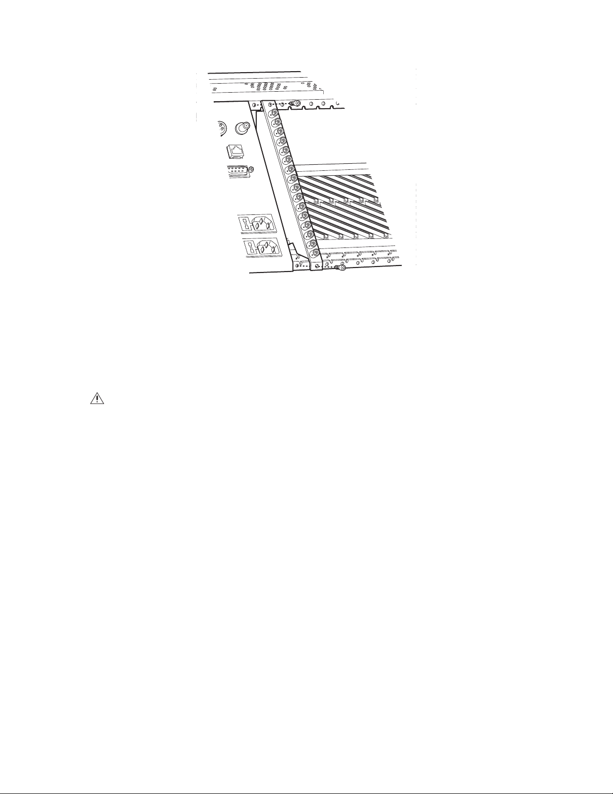
Figure 27. CM9760-RPM Rear Panel Output Card Installation
5. Push the card into place firmly.
6. Tighten the screw at the top and bottom of the card.
7. Connect BNC cables (or ribbon cable, if applicable).
Replacing a CM9760-RPM Card
WARNINGS:
• Rear panel card replacement should be performed by qualified personnel only.
• Electrostatic discharge (ESD) precautions must be observed when replacing a rear panel card. Always wear a grounding strap
connected to an approved grounding source when working on or near exposed electronic equipment.
NOTE: Before replacing a CM9760-RPM card, you must remove the front panel of the matrix bay and disconnect the associated CM9760-VMC
video output card from the connectors on the backplane and from the connector on the CM9760-RPM card that is to be replaced. To disconnect
the CM9760-VMC card, grasp the two card handles and firmly pull the card toward you until the card is disconnected.
Unless the audible alarm on the power supply has been disabled, the alarm beeps and the Frame Fault LED flashes red when the CM9760-VMC
card is disconnected (refer to the Installing or Replacing a CM9760-VMC Video Output Card section for additional information).
To replace a CM9760-RPM card, do the following:
1. Ensure that the associated CM9760-VMC video output card is disconnected as noted above.
2. Disconnect BNC cables (or ribbon cable, if applicable) from the CM9760-RPM card being replaced.
3. Remove the CM9760-RPM card by loosening the screw at the top and bottom of the card and then pulling the card toward you until it is out
of the frame.
4. Install the new card (refer to the Installing a CM9760-RPM Card section).
After the CM9760-RPM card has been replaced, reconnect the associated CM9760-VMC card by sliding the card toward the rear of the matrix
bay until the card is seated firmly with the backplane connectors and CM9760-RPM connector. If the audible alarm on the power supply is
enabled, the alarm stops beeping and the Frame Fault LED turns off.
To ensure proper operation of the CM9760-VMC card, reset the card by pressing the Reset button on the card. For about five seconds, the audible
alarm on the power supply beeps and the Frame Fault LED flashes red. Then reattach the front panel of the matrix bay.
44 C1572M (9/05)
Page 45

INSTALLING OR REPLACING A CM9760-VCC VIDEO INPUT CARD
CM9760-VCC video input cards are installed into the front of the matrix bay behind the front panel. For an initial system installation, the cards
are installed at the factory as ordered. CM9760-VCC cards (and associated rear panel cards) can be added to expand a system or can be replaced
if necessary. To install or replace a CM9760-VCC card, refer to the sections that follow.
INSTALLING A CM9760-VCC CARD
WARNINGS:
• CM9760-VCC video input card installation should be performed by qualified personnel only.
• Electrostatic discharge (ESD) precautions must be observed when installing a CM9760-VCC card. Always wear a grounding strap
connected to an approved grounding source when working on or near exposed electronic equipment.
Before installing a CM9760-VCC card, note the following:
• A CM9760-VCC card can be installed while the matrix bay is powered on.
• A CM9760-VCC card can be installed into any available slot ranging from slot 1 to slot 16, totaling a maximum of 16 CM9760-VCC cards.
A CM9760-VCC card cannot be installed into slot 17—slot 17 is reserved for the CM9760-VMC video output card.
• Each slot position (slots 1-16) into which a CM9760-VCC card can be installed corresponds to a specific range of physical inputs; for
example, slot position 1 corresponds to physical inputs 1-16, slot position 2 corresponds to physical inputs 17-32, and so on. Physical input
numbers are used when programming the CM9760-MXB using the CM9700-MGR; therefore, if you do not install CM9760-VCC cards in
sequential order, be sure to use the correct physical input numbers when programming the CM9760-MXB.
Table F lists the 16 slot positions and their corresponding physical input range.
Table F. CM9760-VCC Slot Positions and Corresponding Physical Input Range
Slot
Position
1 1-16 9 129-144
2 17-32 10 145-160
3 33-48 11 161-176
4 49-64 12 177-192
5 65-80 13 193-208
6 81-96 14 209-224
7 97-112 15 225-240
8 113-128 16 241-256
• The CM9760-VCC card requires a rear panel input card: CM9760-RPC, CM9760-RPL, CM9760-DFC, or CM9760-DFL. The associated rear
panel input card should be installed into the correct slot in the rear of the matrix bay before a CM9760-VCC card is installed.
For instructions to install rear panels cards, refer to the Installing or Replacing Rear Panel Cards section.
Physical
Input Range
Slot
Position
Physical
Input Range
C1572M (9/05) 45
Page 46

To install a CM9760-VCC card, do the following:
1. Remove the front panel of the matrix bay.
2. Insert the CM9760-VCC card into the desired slot (slots 1-16) as follows (refer to Figure 28):
a. Align the top and bottom edges of the card with the top and bottom card guides of the matrix bay.
b. Slide the card toward the rear of the matrix bay until the card is seated firmly with the connectors on the backplane and with the
associated rear panel card connector. Note that, unless the audible alarm on the power supply has been disabled, the alarm beeps
twice and the Frame Fault LED flashes red twice.
The LEDs on the CM9760-VCC card indicate proper operation.
3. Reattach the front panel of the matrix bay.
SLOT 17 (RESERVED FOR
VIDEO INPUT CARDS (SLOTS 1-16)
VIDEO OUTPUT CARD)
CARD HANDLE
FRAME
FAULT
LED
CARD
HANDLE
CARD
GUIDE
Figure 28. CM9760-VCC Video Input Card Installation (Slots 1-16)
46 C1572M (9/05)
Page 47

REPLACING A CM9760-VCC CARD
WARNINGS:
• CM9760-VCC video input card replacement should be performed by qualified personnel only.
• Electrostatic discharge (ESD) precautions must be observed when replacing a CM9760-VCC card. Always wear a grounding strap
connected to an approved grounding source when working on or near exposed electronic equipment.
To replace a CM9760-VCC card, do the following:
1. Remove the front panel of the matrix bay.
2. Remove the CM9760-VCC card to be replaced by grasping the two card handles and firmly pulling the card out of the connectors on the
backplane and associated rear panel card. The card slides out of the slot.
3. Install the new card into the slot of the card being replaced (refer to the Installing a CM9760-VCC Card section for installation instructions).
C1572M (9/05) 47
Page 48

INSTALLING OR REPLACING A CM9760-VMC VIDEO OUTPUT CARD
One CM9760-VMC4, CM9760-VMC8, CM9760-VMC12, or CM9760-VMC16 video output card can be installed in the CM9760-MXB. For an initial
system installation, the CM9760-VMC card is installed at the factory as ordered. If additional matrix bays are ordered to expand an existing
system, the CM9760-VMC card may need to be installed. If necessary, a CM9760-VMC card can be replaced. To install or replace a
CM9760-VMC card, refer to the sections that follow.
INSTALLING A CM9760-VMC CARD
WARNINGS:
• CM9760-VMC video output card installation should be performed by qualified personnel only.
• Electrostatic discharge (ESD) precautions must be observed when installing a CM9760-VMC card. Always wear a grounding strap
connected to an approved grounding source when working on or near exposed electronic equipment.
Before installing a CM9760-VMC card, note the following:
• The CM9760-VMC card can be installed while the matrix bay is powered on.
• The CM9760-VMC card must always be installed into slot 17 in the front of the matrix bay.
• The CM9760-VMC card requires the CM9760-RPM rear panel video output card. The CM9760-RPM card should be installed in the correct
slot in the rear of the matrix bay before the CM9760-VMC card is installed. For instructions to install a CM9760-RPM card, refer to the
Installing a CM9760-RPM Card section.
• When installed in the matrix bay at the factory according to your system order, the S2 DIP switch and X55 and JP2 jumper settings on the
CM9760-VMC card are set in the proper position. You must, however, set DIP switch and jumper settings on a new card as instructed in the
procedure below.
48 C1572M (9/05)
Page 49

To install a CM9760-VMC card, do the following:
1. Remove the front panel of the matrix bay.
2. Remove the blank cover plate of slot 17 by loosening the screw at the top and bottom of the plate.
3. Set the S2 DIP switch and the X55 and JP2 jumpers on the new card to be installed:
a. Refer to Figure 29 for DIP switch and jumper locations on the CM9760-VMC card.
b. Refer to Table G for S2 DIP switch functions and associated settings.
c. Refer to Table H for X55 video standards and associated jumper positions.
d. Ensure that the JP2 jumper is installed in the two-pin header. The JP2 jumper must always be installed for proper operation.
S2
1 2 3 4
ON
JP2
X55
Figure 29. DIP Switch and Jumper Locations on CM9760-VMC Video Output Card
C1572M (9/05) 49
Page 50

Table G. S2 DIP Switch Functions and Settings
Function Options Switch Setting
2400
1 Off
2 Off
1 Off
4800
2On
Baud Rate
1On
9600
2 Off
1On
19200
2On
NTSC* 3 Off
Video Standard
PAL* 3 On
Video Loss
Detection
Enabled 4 On
Disabled (default) 4 Off
*X55 jumper must also be set (refer to Table H).
Table H. X55 Video Standards and Associated Jumper Positions
Video
Standard
Oscillator
Frequency
Pins 1 to 2 Pins 3 to 4 Pins 5 to 6 Pins 7 to 8
Jumper Positions
SECAM1 5.0 MHz On On On On
SECAM2 5.0 MHz On On Off On
624 5.0 MHz On Off On On
PAL/CCIR 5.0 MHz On Off Off On
NTSC1 5.034964 MHz On On On Off
NTSC2 5.034964 MHz On On Off Off
524 5.034964 MHz On Off On Off
PAL-M 5.034964 MHz On Off Off Off
50 C1572M (9/05)
Page 51

4. Install the new card into slot 17 of the matrix bay as follows (refer to Figure 30):
a. Align the top and bottom edges of the card with the top and bottom card guides of the matrix bay.
b. Slide the card toward the rear of the matrix bay until the card is seated firmly with the connectors on the backplane and with the
associated rear panel card connector. If the audible alarm on the power supply is enabled, the alarm stops beeping and the Frame
Fault LED turns off.
c. To ensure proper operation of the CM9760-VMC card, reset the card by pressing the Reset button on the card.
For about five seconds, the audible alarm on the power supply beeps and the Frame Fault LED flashes red. The LEDs on the video
output card then indicate proper operation.
5. Reattach the front panel of the matrix bay.
CARD
GUIDE
VIDEO OUTPUT CARD
(SLOT 17)
CARD
HANDLE
FRAME
FAULT
LED
CARD
HANDLE
CARD
GUIDE
Figure 30. CM9760-VMC Video Output Card Installation (Slot 17)
LEDs
RESET
BUTTON
C1572M (9/05) 51
Page 52

REPLACING A CM9760-VMC CARD
WARNINGS:
• CM9760-VMC video output card replacement should be performed by qualified personnel only.
• Electrostatic discharge (ESD) precautions must be observed when replacing a CM9760-VMC card. Always wear a grounding strap
connected to an approved grounding source when working on or near exposed electronic equipment.
Before replacing a CM9760-VMC card, note the following:
• The CM9760-RPM card can be replaced while the matrix bay is powered on.
• When installed in the matrix bay at the factory according to your system order, the S2 DIP switch and X55 and JP2 jumper settings on the
CM9760-RPM card are set in the proper position. You must, however, set DIP switch and jumper settings on a new card as instructed in the
procedure below.
To replace the CM9760-VMC card, do the following:
1. Remove the front panel of the matrix bay.
2. Remove the CM9760-VMC card to be replaced by grasping the two card handles and firmly pulling the card out of the connectors on the
backplane and associated rear panel card. The card slides out of the slot.
NOTE: Unless the audible alarm on the power supply has been disabled, the alarm beeps and the Frame Fault LED flashes red when the
CM9760-VMC card is removed.
3. Install the new CM9760-VMC card (refer to the Installing a CM9760-VMC Card section). Note that you should set the S2 DIP switch and the
X55 and JP2 jumpers on the new card to match the settings on the card being replaced.
INSTALLING A CM9760-VMM VIDEO OUTPUT MODULE
WARNINGS:
• CM9760-VMM video output module installation should be performed by qualified personnel only.
• Electrostatic discharge (ESD) precautions must be observed. Always wear a grounding strap connected to an approved grounding
source when working on or near exposed electronic equipment.
• When installing a CM9760-VMM module, exercise caution to prevent bending any of the pins on the module.
To install a CM9760-VMM module into an empty slot on a CM9760-VMC4, CM9760-VMC8, or CM9760-VMC12 card, align the pins on the
module with the three sockets on the card (refer to Figure 31) and push the card down carefully until the pins are firmly seated into the sockets.
OUTPUT 0
OUTPUT 2
OUTPUT 1
VIDEO
OUTPUT
MODULES
OUTPUT 3
OUTPUT 4
OUTPUT 5
OUTPUT 6
OUTPUT 7
OUTPUT 8
OUTPUT 9
EMPTY
OUTPUT 10
OUTPUT 11
SLOTS
OUTPUT 13
OUTPUT 12
OUTPUT 15
OUTPUT 14
Figure 31. CM9760-VMM Video Output Module Locations (CM9760-VMC8 Video Output Card)
NOTE: CM9760-VMM slot locations on the CM9760-VMC card are numbered OUTPUT 0 to OUTPUT 15—not OUTPUT 1 to OUTPUT 16.
52 C1572M (9/05)
Page 53

INSTALLING OR REPLACING A POWER SUPPLY
Unless a backup power supply is ordered with the matrix bay, the unit is shipped from the factory with one power supply installed. A backup
power supply can be added to the matrix bay to provide power redundancy to the unit. If necessary, a power supply can be replaced.
Note the following:
• The CM9760-MXB uses the CM9760-MPS power supply (120 VAC, 60 Hz).
• The CM9760-MXB-X uses the CM9760-MPS-X power supply (230 VAC, 50 Hz).
• A power supply provides an audible alarm that operates in conjunction with the Fault LEDs located on the front of the power supply.
By default, the alarm is enabled. You can disable the alarm if desired. For additional information, refer to the Enabling/Disabling the Power
Supply Alarm section.
INSTALLING A BACKUP POWER SUPPLY
NOTE: You can install a backup power supply while the matrix bay is powered on. You do not need to turn off power to the unit.
To install a backup power supply, do the following:
1. Remove the blank plate from the unoccupied power supply slot.
2. Align the power supply in the mounting rails and then slide the power supply into the slot (refer to Figure 32).
3. Press firmly on the front of the power supply until it is firmly seated into the rear connector.
4. Tighten the two captive panel screws at the top and bottom of the power supply.
5. Plug the power cord into the power input receptacle of the power supply.
6. Plug the other end of the power cord into the power source.
7. Place the power switch of the power supply in the On (I) position.
Figure 32. CM9760-MXB Backup Power Supply Installation
C1572M (9/05) 53
Page 54

REPLACING A POWER SUPPLY
To replace a power supply, do the following:
1. Remove the power supply to be replaced as follows:
a. Place the power switch in the Off (0) position.
b. Disconnect the power cord from the power source.
c. Remove the power supply from the power supply slot as follows:
(1) Loosen the two captive panel screws at the top and bottom of the power supply.
(2) Pull the power supply toward you. The power supply slides out of the slot.
2. Install the new power supply as follows:
a. Align the power supply in the mounting rails and then slide the power supply into the slot.
b. Press firmly on the front of the power supply until it is firmly seated into the rear connector.
c. Tighten the two captive panel screws at the top and bottom of the power supply.
d. Plug the power cord into the power source.
e. Place the power switch of the power supply in the On (I) position.
54 C1572M (9/05)
Page 55

REPLACING A POWER SUPPLY FUSE
The rear of the matrix bay provides a separate power input receptacle for each power supply. Each power input receptacle is equipped with a
fuse holder (refer to Figure 33). Each fuse holder provides a spare fuse to be used when replacing a blown fuse.
WARNING: Failure to replace a fuse with a fuse of the same rating can result in serious damage to the matrix bay.
To replace the fuse in a power supply, do the following:
1. Remove the power cord from the power input receptacle.
2. Using a small screwdriver, pry the fuse holder out of the socket. The fuse holder comes out of the unit.
3. Replace the fuse with a fuse of the same rating. If using the spare fuse, be sure to replace it with a fuse of the same rating.
4. Install the fuse holder back into the socket.
5. Plug the power cord into the power input receptacle.
STORAGE DRAWER
FOR SPARE FUSE
FUSE
HOLDER
Figure 33. CM9760-MXB Power Supply Fuse Replacement
C1572M (9/05) 55
Page 56

ENABLING/DISABLING THE POWER SUPPLY ALARM
The power supply provides an audible alarm that operates in conjunction with the Fault LEDs located on the front of the power supply. By default,
the alarm is enabled. The X5 jumper on the power supply allows you to enable/disable the alarm (refer to Figure 34).
To enable/disable the audible power supply alarm, do the following:
1. Place the power switch of the power supply in the Off (0) position.
2. Disconnect the power cord from the power source.
3. Remove the power supply from the power supply slot as follows:
a. Loosen the two captive panel screws at the top and bottom of the power supply.
b. Pull the power supply toward you. The power supply slides out of the slot.
4. Locate the X5 jumper on the power supply (refer to Figure 34).
5. Position the jumper to enable/disable the alarm as shown in Figure 34.
X5
ALARM
DISABLED
ALARM
ENABLED
Figure 34. CM9760-MXB Power Supply Alarm Jumper Positions
6. Install the power supply back into the power supply slot as follows:
a. Align the power supply in the mounting rails and then slide the power supply into the slot.
b. Press firmly on the front of the power supply until it is firmly seated into the rear connector.
c. Tighten the two captive panel screws at the top and bottom of the power supply.
7. Plug the power cord into the power source.
8. Place the power switch of the power supply in the On (I) position.
56 C1572M (9/05)
Page 57

System Programming Using DOS
The CM9700-CC1 runs under Microsoft® DOS (Disk Operating System) 6.22, referred to as MS-DOS® 6.22 and also commonly referred to simply
as DOS. This section provides information about the following:
• System 9760 programming tasks that are performed using DOS operations
• DOS filename conventions
• DOS commands that are commonly used when managing 9760 system files
NOTES:
• For an overview of the DOS directory structure of the CM9700-CC1, refer to Directory Structure in the CM9700-CC1 Controller section.
• For detailed information about programming the 9760 system using the CM9700-MGR, refer to the CM9700-MGR Software Guide.
PERFORMING SYSTEM 9760 DOS PROGRAMMING TASKS
Using DOS operations, you can perform the following tasks:
• Copy configuration files from the CM9700-MGR to the CM9700-CC1
• Set and adjust system time in a single-node system
• Set and adjust system time in a multi-node system
To perform each of the above tasks, refer to the sections that follow.
COPYING CONFIGURATION FILES FROM THE CM9700-MGR TO THE CM9700-CC1
NOTE: Before copying configuration files from the CM9700-MGR to the CM9700-CC1, it is recommended that you save a copy of the existing
CM9700-CC1 configuration files.
To copy configuration files from the CM9700-MGR to the CM9700-CC1, do the following:
1. Export configuration files from the CM9700-MGR to a floppy disk using the Export to Configuration Files option of the CM9700-MGR.
For detailed instructions, refer to the CM9700-MGR Software Guide.
2. Insert the floppy disk into the disk drive of the CM9700-CC1.
3. Using the keyboard connected to the AT-compatible keyboard port of the CM9700-CC1, press Ctrl+Q to exit the 9760 system.
The VGA monitor displays the C:\9700> prompt.
4. At the prompt, copy all configuration files from the floppy disk to the CM9700-CC1 by entering the following:
copy a:filename.*
where filename is the root name of the configuration files. For example, if the root name is NODE1, enter the following:
copy a:node1.*
5. Press Enter.
Either of the following occurs:
• The configuration files are copied to the CM9700-CC1. Skip step 6 and proceed to step 7.
• If the previous configuration files exist in the C:\9700 directory, the following message appears:
Files Already Exist, Over Write? Y/N/A
Continue with step 6.
6. Enter A to overwrite all existing files on the CM9700-CC1 with the files contained on the floppy disk.
Entering Y for Yes requires that you confirm on a file-by-file basis that you wish to overwrite the existing file. Entering N for No
NOTE:
requires that you confirm on a file-by-file basis that you do not wish to overwrite the existing file.
7. Remove the floppy disk from the disk drive of the CM9700-CC1.
8. Press Ctrl+Alt+Delete to reboot the CM9700-CC1. Note that you must press the Del key on the numeric keypad of your keyboard in order to
reboot the system.
C1572M (9/05) 57
Page 58

SETTING AND ADJUSTING SYSTEM TIME IN A SINGLE-NODE SYSTEM
You can set system time in a single-node system using the PC keyboard that is connected to the AT-compatible keyboard port of the
CM9700-CC1. Using the CM9700-CC1 PC keyboard, you can also adjust system time if the system clock is running fast (system lead time) or slow
(system lag time). For detailed instructions to set and adjust system time, refer to the sections that follow.
NOTE: System time can also be set using the CM9760-KBD rather than the CM9700-CC1 PC keyboard; however, to adjust system time, the
CM9700-CC1 PC keyboard must be used.
Setting System Time in a Single-Node System
Before setting system time, note the following:
• Begin the process of setting system time close to the top of the hour.
• When setting system time, you must synchronize the system clock to a reference time clock (RTC).
• In a configuration having a CM9760-HS hot switch, setting and adjusting time on one CM9700-CC1 synchronizes the time between both
CM9700-CC1s. (For detailed information about the CM9760-HS hot switch, refer to the CM9760-HS Hot Switch Installation/Operation
manual.)
To set the system time using the CM9700-CC1 PC keyboard, do the following:
1. From the CM9700-CC1 diagnostic screen, press Alt+N to display the current configuration filename.
The configuration filename is displayed in the System box. You will need to enter the name later in this procedure when directed.
2. Press Ctrl+Q to exit the 9760 system.
The C:\9700> prompt appears.
3. At the prompt, enter time and then press Enter.
The currently set time is displayed and the following prompt appears:
Enter new time:
4. Do the following:
a. Enter a time equaling the top of the hour in the xx:xx:xx.xx format followed by the letter a for AM or p for PM (for example,
2:00:00.00p for 2:00 PM). Do not press Enter.
b. Wait for the RTC to approach the top of the hour.
c. When the RTC equals the top of the hour, press Enter.
5. At the C:\9700> prompt, invoke the system executable by entering startup and then pressing Enter.
After the CM9700-CC1 initializes, the CM9700-CC1 diagnostic screen appears. In addition, the system time entered in step 4 is displayed
on all monitors in the system.
After the system has run 24 hours or a multiple of 24 hours, you can adjust system time if the system clock is running fast or slow when
compared to the RTC. To adjust system time, refer to the Adjusting System Time in a Single-Node System section.
58 C1572M (9/05)
Page 59

Adjusting System Time in a Single-Node System
To adjust system time in a single-node system, do the following:
1. Wait 24 hours—or a multiple of 24 hours if necessary—since the system time was set, and then compare the system time displayed on
any monitor in the system with the RTC time. Note the difference in time for a 24-hour period and whether the system time is ahead of or
behind RTC time. For example, if system time is 2:02:30 PM and RTC time is 2 PM after a 24-hour period, then system time is ahead of RTC
time by 2 minutes and 30 seconds.
If the amount of time over which you are comparing system time to RTC time is a multiple of 24 hours, perform steps a-c that follow to
determine the difference in time per 24-hour period; otherwise, proceed to step 2.
a. Convert the time difference noted between system time and RTC time to seconds.
b. Divide the total number of seconds by the elapsed time in hours to determine the seconds per hour rate of change. For example, if a
90-second time difference had occurred over a time interval of 3 days or 72 hours, then the rate of change in seconds per hour is 1.25
(90 divided by 72 = 1.25).
c. Multiply the seconds per hour rate of change by 24 to obtain the time difference in seconds for a 24-hour period. For example,
multiplying 1.25 by 24 equals a time difference of 30 seconds per 24-hour period.
2. Using the CM9760-KBD, set system time at the top of the hour in 24-hour format. For example, if RTC time equals 2:00 PM, enter the
following:
14 00 00
3. At the CM9700-CC1 diagnostic screen, press Alt+L using the CM9700-CC1 PC keyboard.
The System box displays the following:
System :-Last Adj 0:0.0 Total 0:0.0
4. Enter the time difference noted in step 1 in the following format:
–mm.ss.hh or mm:ss.hh
where:
• – = minus sign. A minus sign must be entered if system time is ahead of RTC time and must be slowed for synchronization with
RTC time.
• mm = minutes
• ss = seconds
• hh = hundredths of a second
For example, to enter the time difference of 2 minutes and 30 seconds noted in step 1 in order to slow system time over the next 24 hours,
enter the following:
–02:30.00
5. Press Enter.
6. Press Alt+L to display the adjustment you have made to system time.
The adjustment is displayed in the System box on the diagnostic screen. For example, for the time difference of 2 minutes and 30 seconds
that was entered in step 4 above, the System box displays the following:
Last Adj. –2:30.0 Total –2.30.0
where:
Last Adj. displays the last time adjustment that was made in minutes, seconds, and hundredths of a second. In the example, the last
adjustment that was made is –2:30.0.
Total displays the total time adjustment that was made in minutes, seconds, and hundredths of a second. In the example, the total
adjustment that was made is –2:30.0.
After the system has run 24 hours or a multiple of 24 hours after the time adjustment was made, you can adjust the system time again if
necessary. To make additional adjustments to system time, refer to the Making Additional Adjustments to System Time section.
C1572M (9/05) 59
Page 60

NOTE: The time adjustment that was made to system time as displayed in step 6 above is a temporary time adjustment. If you reboot the
CM9700-CC1 by pressing Ctrl+Alt+Del or exit the 9760 system by pressing Ctrl+Q, the time adjustment reverts to 0:0.0. As a result, you must edit
the startup.bat file to permanently program the total time adjustment indicated in the System box after the final time adjustment is made.
Instructions for editing the startup.bat file are provided in the Editing the Startup.bat File to Permanently Adjust System Time section.
Making Additional Adjustments to System Time
To make an additional adjustment to system time, do the following:
1. Wait 24 hours—or a multiple of 24 hours if necessary—since the last time adjustment was made, and then compare the system time
displayed on any monitor in the system with the RTC time. Note the difference in time for a 24-hour period and whether the system time is
ahead of or behind RTC time.
2. Using the CM9760-KBD, set system time at the top of the hour in 24-hour format when the RTC reaches the top of the hour.
3. At the CM9700-CC1 diagnostic screen, press Alt+L.
The System box displays the latest time adjustment values. For example, if a time adjustment of –2:30.00 was entered to slow system time
2 minutes and 30 seconds, the System box displays the following:
Last Adj. –2:30.0 Total –2.30.0
4. Enter a new time adjustment based on adding or subtracting time from the last time adjustment that was made. For example, when
comparing system time with RTC time after five 24-hour periods have passed since the last time adjustment was made and determining
that system time is running 10 seconds slow—an average of 2 seconds slower for each 24 hours of elapsed time—you can change the last
time adjustment by adding 2 seconds. If the last time adjustment was –02:30.00, the following time adjustment must be entered as follows
to add 2 seconds:
–02:28.0
Note that –02.28.0 is derived from the following equation: [(–02:30.0) + (00:02.0)] = –02.28.0
5. Press Enter.
The System box displays the last time adjustment and total time adjustment values. In the example, the System box displays the following:
Last Adj. –2:28.0 Total –4.58.0
Note that the total time adjustment is –4.58.0.
6. If necessary, continue to make additional time adjustments until the system clock and RTC are synchronized.
NOTE: The time adjustments that are made to system time are temporary time adjustments. If you reboot the CM9700-CC1 by pressing
Ctrl+Alt+Del or exit the 9760 system by pressing Ctrl+Q, the time adjustment values revert to 0:0.0. As a result, you must edit the startup.bat file
to permanently program the total time adjustment indicated in the System box after the final time adjustment is made. Instructions for editing
the startup.bat file are provided in the Editing the Startup.bat File to Permanently Adjust System Time section.
60 C1572M (9/05)
Page 61

Editing the Startup.bat File to Permanently Adjust System Time
To permanently adjust system time, you must edit the startup.bat file to include the total time adjustment indicated in the System box after the
final adjustment is made to system time. To edit the startup.bat file to include the total time adjustment, do the following:
1. Press Ctrl+Q to exit the 9760 system.
The C:\9700> prompt appears.
2. At the prompt, enter edit startup.bat and then press Enter.
The startup.bat file opens and appears as follows:
CM9700 NODEx
where:
x is the node number:
• NODE1 is the default configuration filename for a single-node system.
• Default configuration filenames for each node within a multi-node system are numbered sequentially according to the CM9700-NW1
port number to which each CM9700-CC1 is connected, for example, NODE5 and NODE6 in a two-node system.
3. Edit the startup.bat file to include the total time adjustment as follows:
CM9700 NODEx /T:–mm:ss:hh
or
CM9700 NODEx /T:mm:ss:hh
where:
• /T = time adjustment switch command
• – = minus sign. A minus sign must be entered if system time is ahead of RTC time and must be slowed for synchronization with
RTC time.
• mm = minutes
• ss = seconds
• hh = hundredths of a second
For example, to enter the total time adjustment of 4 minutes and 58 seconds to slow the system clock in a 24-hour period, edit the
startup.bat file as follows:
CM9700 NODEx /T:-04:58:00
4. Press Alt+F and then type the letter s to save the file.
5. Press Alt+F and then type the letter x to exit the file.
6. At the C:\9700 prompt, enter startup and then press Enter to restart the system.
The time adjustment is now permanent. If you reboot the CM9700-CC1 by pressing Ctrl+Alt+Del or exit the 9760 system by pressing Ctrl+Q,
the time adjustment remains in system memory and does not revert to 0:0.0.
C1572M (9/05) 61
Page 62

SETTING AND ADJUSTING SYSTEM TIME IN A MULTI-NODE SYSTEM
You can set system time in a multi-node system using the PC keyboard that is connected to the AT-compatible keyboard port of the
CM9700-NW1. The CM9700-NW1 then provides system timing to the network. Using the CM9700-NW1 PC keyboard, you can also adjust
system time if the system clock is running fast (system lead time) or slow (system lag time). For detailed instructions to set and adjust system
time, refer to the sections that follow.
NOTE: System time can also be set using the CM9760-KBD rather than the CM9700-NW1 PC keyboard; however, to adjust system time, the
CM9700-NW1 PC keyboard must be used.
Setting System Time in a Multi-Node System
Before setting system time, note the following:
• Begin the process of setting system time close to the top of the hour.
• When setting system time, you must synchronize the system clock to a reference time clock (RTC).
• If the CM9700-NW1 goes offline, each node reverts to its own internal system time.
To set system time using the CM9700-NW1 PC keyboard, do the following:
1. Press Ctrl+Q to exit the CM9700-NW1 diagnostic screen.
The screen provides a display similar to the following:
Program end. Vectors reset.
11:36:49.12 Mon 06-22-2005 C:\NETWORK>_
2. At the prompt, enter time and then press Enter.
The currently set time is displayed and the following prompt appears:
Enter new time:
3. Do the following:
a. Enter a time equaling the top of the hour in the xx:xx:xx.xx format followed by the letter a for AM or p for PM (for example,
2:00:00.00p for 2:00 PM). Do not press Enter.
b. Wait for the RTC to approach the top of the hour.
c. When the RTC equals the top of the hour, press Enter.
4. At the C:\NETWORK> prompt, invoke the system executable by entering net and then press Enter.
The system time entered in step 3 is displayed on all monitors in the system.
After the system has run 24 hours or a multiple of 24 hours, you can adjust system time if the system clock is running fast or slow when
compared to the RTC. To adjust system time, refer to the Adjusting System Time in a Multi-Node System section.
62 C1572M (9/05)
Page 63

Adjusting System Time in a Multi-Node System
To adjust system time in a multi-node system, do the following:
1. Wait 24 hours—or a multiple of 24 hours if necessary—since the system time was set, and then compare the system time displayed on
any monitor in the system with the RTC time. Note the difference in time for a 24-hour period and whether the system time is ahead of or
behind RTC time. For example, if system time is 2:02.30 PM and RTC time is 2 PM after a 24-hour period, then system time is ahead of RTC
time by 2 minutes and 30 seconds.
If the amount of time over which you are comparing system time to RTC time is a multiple of 24 hours, perform steps a-c that follow to
determine the difference in time per 24-hour period; otherwise, proceed to step 2.
a. Convert the time difference noted between system time and RTC time to seconds.
b. Divide the total number of seconds by the elapsed time in hours to determine the seconds per hour rate of change. For example, if a
90-second time difference had occurred over a time interval of 3 days or 72 hours, then the rate of change in seconds per hour is 1.25
(90 divided by 72 = 1.25).
c. Multiply the seconds per hour rate of change by 24 to obtain the time difference in seconds for a 24-hour period. For example,
multiplying 1.25 by 24 equals a time difference of 30 seconds per 24-hour period.
2. Using the CM9760-KBD, set system time at the top of the hour in 24-hour format. For example, if RTC time equals 2:00 PM, enter the
following:
14 00 00
3. At the CM9700-NW1 diagnostic screen, press Alt+L using the CM9700-NW1 PC keyboard.
The screen provides a display similar to the following:
**********TIME ADJUSTMENT*********
Last Time Adjustment 0:0.0
Total Time Adjustment 0:0.0
Format Example
+10:20.5 Adds 10 min 20.5 seconds per day
-5:10.61 Subtracts 5 min 10.61 seconds per day
***********ESC TO CANCEL**********
=>
4. At the => system prompt, enter the time difference noted in step 1 in the following format:
–mm.ss.hh or mm:ss.hh
where:
• – = minus sign. A minus sign must be entered if system time is ahead of RTC time and must be slowed for synchronization with
RTC time.
• mm = minutes
• ss = seconds
• hh = hundredths of a second
For example, to enter the time difference of 2 minutes and 30 seconds noted in step 1 in order to slow system time over the next 24 hours,
enter the following:
–02:30.00
C1572M (9/05) 63
Page 64

5. Press Enter.
The adjustment is displayed. For example, for the adjustment of –02.30.00 that was made in step 4, the following line appears:
Last Adj. –2:30.0 Total –2.30.0
where:
Last Adj. displays the last time adjustment that was made in minutes, seconds, and hundredths of a second. In the example, the last
adjustment that was made is –2:30:0.
Total displays the total time adjustment that was made in minutes, seconds, and hundredths of a second. In the example, the total
adjustment that was made is –2:30.0.
6. If desired, press Alt+N to check the system time.
The line containing the system time appears similar to the following:
Fri June 24 15:40:23 2005 CM9700 NIU Ver xxx xxx Setup file:2nodes.niu
After the system has run 24 hours or a multiple of 24 hours since a time adjustment was made, you can adjust the system time again if
necessary. To make additional adjustments to system time, refer to the Making Additional Adjustments to System Time section.
NOTE: The time adjustment that was made to system time as displayed in step 5 above is a temporary time adjustment. If you reboot the
CM9700-NW1 by pressing Ctrl+Alt+Del or stop operation of the CM9700-NW1 by pressing Ctrl+Q, the time adjustment reverts to 0:0.0. As a
result, you must edit the net.bat file to permanently program the total time adjustment indicated on the diagnostic screen after the final time
adjustment is made. Instructions for editing the net.bat file are provided in the Editing the Net.bat File to Permanently Adjust System Time
section.
64 C1572M (9/05)
Page 65

Making Additional Adjustments to System Time
To make an additional adjustment to system time, do the following:
1. Wait 24 hours—or a multiple of 24 hours if necessary—since the last time adjustment was made, and then compare the system time
displayed on any monitor in the system with the RTC time. Note the difference in time for a 24-hour period and whether the system time is
ahead of or behind RTC time.
2. Using the CM9760-KBD, set system time at the top of the hour in 24-hour format when the RTC reaches the top of the hour.
3. At the CM9700-NW1 diagnostic screen, press Alt+L.
The screen displays the latest time adjustment that was made. For example, if a time adjustment of –2:30.0 was entered to slow system
time 2 minutes and 30 seconds, the screen displays the following:
**********TIME ADJUSTMENT*********
Last Time Adjustment –2:30.0
Total Time Adjustment –2:30.0
Format Example
+10:20.5 Adds 10 min 20.5 seconds per day
-5:10.61 Subtracts 5 min 10.61 seconds per day
***********ESC TO CANCEL**********
=>
4. At the => system prompt, enter a new time adjustment based on adding or subtracting time from the original time adjustment. For example,
when comparing system time with RTC time after five 24-hour periods have passed since the original time adjustment was made and
determining that system time is running 10 seconds slow—an average of 2 seconds slower for each 24 hours of elapsed time—you can
change the original time adjustment by adding 2 seconds. If the original time adjustment was –02:30.00, the following time adjustment
must be entered as follows to add 2 seconds:
–02:28.0
Note that –02.28.0 is derived from the following equation: [(–02:30.0) + (00:02.0)] = –02.28.0
5. Press Enter.
The adjustment is displayed. For example, for the adjustment of –02.28.0 that was made in step 4, the following line appears:
Last Adj. –2:28.0 Total –4.58.0
Note that the total time adjustment is –4.58.0.
6. If desired, press Alt+N to check the system time.
The line containing the system time appears similar to the following:
Sat June 25 15:40:18 2005 CM9700 NIU Ver xxx xxx Setup file:2nodes.niu
7. If necessary, continue to make additional time adjustments until the system clock and RTC are synchronized.
NOTE: The time adjustments that are made to system time are temporary time adjustments. If you reboot the CM9700-NW1 by pressing
Ctrl+Alt+Del or stop operation of the CM9700-NW1 by pressing Ctrl+Q, the time adjustment values revert to 0:0.0. As a result, you must edit the
net.bat file to permanently program the total time adjustment indicated on the diagnostic screen after the final time adjustment is made.
Instructions for editing the net.bat file are provided in the Editing the Net.bat File to Permanently Adjust System Time section.
C1572M (9/05) 65
Page 66

Editing the Net.bat File to Permanently Adjust System Time
To permanently adjust system time, you must edit the net.bat file to include the total time adjustment indicated on the diagnostic screen after the
final adjustment is made to system time. To edit the net.bat file to include the total time adjustment, do the following:
1. Press Ctrl+Q to stop operation of the CM9700-NW1.
The screen displays the following:
Program end. Vectors reset.
11:36:49.12 Mon 06-27-2005 C:\NETWORK>_
2. At the prompt, enter edit net.bat and then press Enter.
The net.bat file opens and appears as follows:
9700NIU xNODES
where x equals the number of nodes in the network when the CM9700-NW1 is shipped as part of a system order, for example,
2NODES.NIU for a two-node system, 3NODES.NIU for a three-node system, and so on. The default configuration file name is 2NODES.NIU
when the CM9700-NW1 is shipped as a standalone unit.
3. Edit the net.bat file to include the total time adjustment as follows:
9700NIU xNODES /T:-mm:ss:hh
or
9700NIU xNODES /T:mm:ss:hh
where:
• /T = time adjustment switch command
• – = minus sign. A minus sign must be entered if system time is ahead of RTC time and must be slowed for synchronization with
RTC time.
• mm = minutes
• ss = seconds
• hh = hundredths of a second
For example, to enter the total time adjustment of 4 minutes and 58 seconds to slow the system clock in a 24-hour period, edit the net.bat
file as follows:
9700NIU xNODES /T:-04:58:00
4. Press Alt+F and then type the letter s to save the file.
5. Press Alt+F and then type the letter x to exit the file.
6. At the C:\NETWORK prompt, enter net and then press Enter to restart the system.
The time adjustment is now permanent. If you reboot the CM9700-NW1 by pressing Ctrl+Alt+Del or stop operation of the CM9700-NW1,
the time adjustment remains in memory and does not revert to 0:0.0.
66 C1572M (9/05)
Page 67

DOS FILENAME CONVENTIONS
The naming convention for a DOS filename is a root name followed by a period followed by an extension:
• The root name is limited to eight characters with no spaces.
• The extension is three characters.
For example, if the filename is NODE1.CAM, the root name is NODE1 and the extension is CAM.
The following characters cannot be used in the root name or extension. The characters are reserved for particular uses as follows:
\ (backslash) Used for directory navigation
/ (forward slash) Used as a delimiter in command line options
: (colon) Used for a command prompt
. (dot) Used as a separator between root and extension
* (asterisk) Used as a wildcard character
? (question mark) Used as a wildcard character
> (greater than symbol) Used as a command prompt
< (less than symbol) Used as a command prompt
DOS COMMAND REFERENCE
Table I provides a listing of DOS commands that are commonly used when managing 9760 system files.
Table I. DOS Command Reference
Command
CD Displays the current
†
Switch††Description Example(s)§¶
Directory Management Commands
directory.
Changes the current
directory.
C:\>CD Displays the root directory as
the current directory: C:\>
C:\>CD 9700 Changes from the root direc-
tory (C:\) to the 9700 directory:
C:\9700>
C:\>CD 9700\BKUP Changes from the root direc-
tory to the BKUP directory
within the 9700 directory:
C:\9700\BKUP>
C:\9700>CD.. Moves up one level in the
directory structure. In the
example, moves from the 9700
directory to the root directory.
C:\9700\BKUP>CD\ Changes to the root directory.
In the example, changes from
the C:\9700\BKUP directory to
the root directory.
C:\>CD A: Changes from the root
directory to the A drive.
DIR Displays a list of files
and subdirectories
within the specified
directory.
/W Displays the contents of
a directory in wide
format. Up to five filenames or directory
names are displayed on
one line.
C1572M (9/05) 67
C:\>DIR Displays a list of files and
subdirectories within the root
directory (C:\).
C:\>DIR/W Displays the contents of the
root directory in wide format.
Page 68

Table I. DOS Command Reference (Continued)
Command
†
Switch††Description Example(s)§¶
Directory Management Commands (Continued)
DIR (Continued) /P Displays the contents of
a directory one screen at
a time.
/W/P Combines /W and /P
switches to display the
contents of a directory
C:\>DIR/P Displays the contents of the
root directory one screen at a
time.
C:\>DIR/W/P Displays the contents of the
root directory in wide format
one screen at a time.
in wide format one
screen at a time.
MD Creates a directory C:\9700>MD FACTORY Creates a directory named
FACTORY within the 9700
directory.
RD
or
RMDIR
Removes the specified
directory. The directory
to be removed must not
C:\>RD NETWORK
or
C:\>RMDIR NETWORK
Removes the NETWORK
directory if empty.
contain any files or subdirectories—the directory must be empty
except for the single-dot
(.) and double-dot (..)
entries.
TREE Displays the directory
structure of the
specified directory and
those below it.
File and Disk Management Commands
COPY Copies a single file or a
group of files from one
location to another
location.
C:\TREE Displays the directories in the
root directory and any
associated subdirectories.
C:\>COPY A:\NODE1.MON C:\9700 Copies the NODE1.MON file
from the floppy disk in drive A
to the C:\9700 directory.
C:\>COPY A:\NODE1.* C:\9700 Copies all files with the
NODE1 root name from the
floppy disk in drive A to the
C:\9700 directory.
C:\9700>COPY A:NODE1.* Copies all files with the
NODE1 root name from the
floppy disk in drive A to the
C:\9700 directory.
A:\>COPY NODE1.* C:\9700 Copies all files with the
NODE1 root name from the
floppy disk in drive A to the
C:\9700 directory.
C:\>COPY A:\*.* C:\9700 Copies all files from the floppy
disk in drive A to the C:\9700
directory.
C:\9700>COPY NODE1.* A: Copies all files with the
NODE1 root name from the
C:\9700 directory to the A
drive.
68 C1572M (9/05)
Page 69

Table I. DOS Command Reference (Continued)
Command
†
Switch††Description Example(s)§¶
File and Disk Management Commands (Continued)
DEL Deletes a single file or a
group of files from the
specified location.
NOTE: You can restore
deleted files using the
UNDELETE command.
WARNING: Be careful
that you do not delete
necessary system or
configuration files.
/P Prompts you for confir-
mation before deleting a
file.
EDIT Starts the MS-DOS
editor, which is a text
editor that can be used
to create and edit ASCII
text files.
C:\>DEL C:\9700\OLDFILE.MON Deletes the OLDFILE.MON file
from the C:\9700 directory.
C:\9700>DEL OLDFILE.MON Deletes the OLDFILE.MON file
from the C:\9700 directory.
C:\>DEL A:OLDFILE.MON Deletes the OLDFILE.MON file
from the floppy disk in drive A.
A:\>DEL OLDFILE.MON Deletes the OLDFILE.MON file
from the floppy disk in drive A.
C:\9700>DEL OLDFILE.* Deletes all files with the
OLDFILE root name from the
C:\9700 directory.
C:\9700>DEL OLDFILE.* /P Prompts you for confirmation
before deleting each file with
the OLDFILE root name from
the C:\9700 directory.
C:\9700>EDIT STARTUP.BAT Allows you to edit the
startup.bat file.
FORMAT Formats a disk for use
with DOS. If data is
present on the disk, the
data is erased.
WARNING: Do not
format the C: drive.
/S Transfers operating sys-
tem files to a newly formatted floppy disk that
can be used as the system disk, allowing you
to boot from the disk.
REN Changes the name of a
single file or a group of
files. For information
about DOS filename
conventions, refer to the
DOS Filename Conventions section.
C:\>FORMAT A: Formats the floppy disk in drive
A for use with DOS.
C:\>FORMAT A:\S Transfers operating system
files to a newly formatted
floppy disk in drive A.
——
C1572M (9/05) 69
Page 70

Table I. DOS Command Reference (Continued)
Command
†
Switch††Description Example(s)§¶
File and Disk Management Commands (Continued)
TYPE Displays the contents of
the specified text file on
the screen. If the location of the file is in a
directory other than the
one you are in, you must
specify the directory
path.
| MORE Allows a long text file to
be viewed one screen at
a time. The | redirection
operator symbol
precedes the MORE
command. The symbol is
located above the
backslash (\) on the
keyboard.
UNDELETE Recovers files that were
previously deleted using
the DEL command.
/LIST Lists the deleted files
that are available to be
recovered but does not
recover any files.
C:\9700>TYPE NODE1.MON Displays the contents of the
NODE1.MON file located in
the C:\9700 directory
C:\>TYPE C:\9700\NODE1.MON Displays the contents of the
NODE1.MON file located in
the C:\9700 directory
C:\ TYPE C:\9700\NODE1.ALM | MORE Allows the NODE1.ALM text
file to be viewed one screen at
a time
C:\UNDELETE C:\9700\TEST.BAT Recovers the TEST.BAT file
that was previously deleted
using the DEL command.
C:\UNDELETE C:\9700\ /LIST Lists the files that have been
deleted from the C:\9700 direc-
tory and are available to be
recovered but does not recover
the files.
/ALL Recovers deleted files
without prompting for
confirmation for each
file
Environment Commands
PATH Displays the current
search path used when
DOS looks for a program
file.
PATH [drive:][path[;…]] Sets the search path to
be used when DOS
looks for a program file
Miscellaneous Commands
CLS Clears the screen. Only
the command prompt
and cursor remains.
FASTHELP Lists and briefly
describes MS-DOS
commands. Provides
less detail than the
information provided by
the HELP command
(see below).
C:\UNDELETE C:\9700\ /ALL Recovers all files that have
been deleted from the C:\9700
directory without prompting
for confirmation for each file
C:\>PATH —
C:\>PATH C:;C:\DOS;C:\WINDOWS Sets the search path to
C:;C:\DOS;C:\WINDOWS
C:\>CLS Clears the screen. The follow-
ing remains: C:\>_
C:\>FASTHELP —
70 C1572M (9/05)
Page 71

Table I. DOS Command Reference (Continued)
Command
†
Switch††Description Example(s)§¶
Miscellaneous Commands (Continued)
FASTHELP command Briefly describes the
specified command.
Provides less detail than
the information provided
by HELP command (see
below).
HELP Starts the MS-DOS
command reference,
which provides detailed
information about
MS-DOS commands.
HELP command Displays detailed
information about the
specified command only.
MORE Displays one screen of
information at a time.
Can also be used with
the TYPE command
when viewing a long
text file. When MORE
follows a command, the
| redirection operator
symbol is used. The
symbol is located above
the backslash (\) on the
keyboard.
C:\FASTHELP DIR Displays brief information
about the DIR command.
C:\HELP —
C:\HELP DIR Displays detailed information
about the DIR command.
C:\DIR C:\DOS | MORE Displays the contents of the
DOS directory one screen at a
time.
VER Displays the current
C:\VER —
version of DOS.
†
DOS commands can be entered in lowercase or uppercase.
††
A switch modifies the way DOS carries out a command. Generally, a switch consists of a forward slash (/) followed by one or more letters or
numbers.
§
An asterisk (*) used in the examples denotes a wildcard. The asterisk matches any character in that position and all the positions that
follow. The asterisk can be used to manage (for example, copy or delete) a group of configuration files without the need to manage each
configuration file individually.
NOTE: The root directory does not have a name. It is simply referred to as a backslash (\). Entering the CD\ command from any directory
always returns you to the root directory, which is denoted by the command prompt C:\>.
C1572M (9/05) 71
Page 72

System Diagnostics
The 9760 system provides diagnostic screens that allow you to monitor single-node and multi-node status. This section provides information
about the following:
• Monitoring CM9700-CC1 functions using the CM9700-CC1 diagnostic screen and associated PC keyboard commands
• Viewing multi-node system status using the CM9700-NW1 diagnostic screen and associated PC keyboard commands
NOTE: Additional displays, such as those provided by the CM9700-MGR Main window and the CM9760-KBD LCD, also provide information
about system status. For detailed information, refer to the product-specific documentation.
MONITORING CM9700-CC1 FUNCTIONS
The CM9700-CC1 provides a diagnostic screen that allows you to monitor CM9700-CC1 functions. You can view the diagnostic screen on a VGA
monitor that is connected to the VGA port on the rear of the CM9700-CC1. The diagnostic screen appears after the CM9700-CC1 initializes.
Refer to Figure 35 for a sample CM9700-CC1 diagnostic screen.
MONITOR
BOXES (8)
CONFIGURATION
INFORMATION
CM9700-CC1
SOFTWARE
GPI AND
AUXILIARY
BOX
SYSTEM
BOX
VERSION
Figure 35. Sample CM9700-CC1 Diagnostic Screen
As illustrated in Figure 35, the CM9700-CC1 diagnostic screen displays the following items:
• Monitor boxes: Up to eight monitor boxes are displayed on the CM9700-CC1 diagnostic screen at one time. Each monitor box represents a
monitor and the camera currently being displayed on that monitor (for detailed information about the monitor box, refer to the Viewing
Monitor Box Diagnostics section).
• GPI and auxiliary box: Displays GPI and auxiliary information (if applicable):
– GPI displays the GPI currently selected. The GPI number is updated when an auxiliary command is executed.
– Ax displays the auxiliary currently selected and whether the auxiliary is on or off.
• System box: Displays system status messages, error messages, and responses to commands issued from the PC keyboard that is connected
to the AT-compatible port of the CM9700-CC1.
• Configuration information: Indicates whether the CM9700-CC1 is part of a CM9760-HS hot switch configuration. Note that A OFF indicates
that the CM9700-CC1 is not part of a hot switch configuration. (The letter A indicates asynchronous mode.) For detailed information about
the diagnostic screen in a hot switch configuration, refer to the CM9760-HS Hot Switch Installation/Operation manual.
• CM9700-CC1 software version: Displays the software version number (xxx xxx) of the CM9700.EXE executable file (for example, version
903 023 which represents version 9.03.023).
72 C1572M (9/05)
Page 73

VIEWING MONITOR BOX DIAGNOSTICS
The monitor box on the CM9700-CC1 diagnostic screen provides information about the monitor, camera, auxiliary conditions, and alarms
currently being displayed. Refer to Figure 36 for a sample monitor box.
LOGICAL ALARM
LOGICAL
CAMERA
NUMBER
CAMERA
AUXILIARIES
LOGICAL
MONITOR
NUMBER
Figure 36. Sample Monitor Box on CM9700-CC1 Diagnostic Screen
As illustrated in Figure 36, a monitor box displays the following information:
• Logical camera number: Identifies the logical number of the selected camera. Note that the letters CC denote that the camera is a
controllable camera. If the letters CC do not appear for a particular camera, the camera is a fixed camera.
• Camera auxiliary numbers 1-8: Indicate whether auxiliaries 1-8 are on or off. An auxiliary number appears white when the corresponding
auxiliary is off and changes color when the corresponding auxiliary is turned on.
• Logical monitor number: Identifies the logical number of the selected monitor.
• Logical alarm number: Identifies the logical number of an alarm that has been triggered.
• Focus indication lines: Indicate when a camera is focused near or far. When a camera is focused near, the distance between the lines
increases. When a camera is focused far, the distance between the lines decreases.
• Iris: Indicates when the iris of the camera is being opened or closed. When the iris is being opened, the black area inside the circle
increases. When the iris is being closed, the black area decreases.
• Zoom and joystick control box: Indicates when a camera is zoomed in or out. When a camera is zoomed in, the box becomes larger. When a
camera is zoomed out, the box becomes smaller.
The box also displays camera movement by mimicking joystick control.
NUMBER
FOCUS
INDICATION LINES
ZOOM AND
JOYSTICK
CONTROL BOX
Note that each monitor box that is assigned to a camera is displayed in a color. The color of the monitor box changes when a different camera is
selected. When a monitor box appears empty, a camera is not selected.
C1572M (9/05) 73
Page 74

ALLOCATING MONITORS TO MONITOR BOXES
When the diagnostic screen appears on the VGA monitor after the CM9700-CC1 is initialized, the first eight monitors are displayed in the eight
monitor boxes. Using the PC keyboard connected to the AT-compatible keyboard port of the CM9700-CC1, you can allocate a different monitor to
a monitor box by using the function keys F1 through F8. The function keys correspond to the monitor boxes:
• The top four monitor boxes are 1 to 4 (from left to right); therefore, F1 corresponds to monitor box 1, F2 corresponds to monitor box 2, and
so on.
• The bottom four monitor boxes are 5 to 8; therefore, F5 corresponds to monitor box 5, F6 corresponds to monitor box 6, and so on.
To allocate a monitor to a monitor box, do the following:
1. Press the function key corresponding to the monitor box to which you want to want to assign a different monitor. For example, press F1 if
you want to assign monitor box 1 a different monitor.
In the System box, the following prompt appears:
Allocate Box [x] to ?
where x is the number of the desired monitor box (1-8). For example, pressing the F1 key causes the following prompt to appear:
Allocate Box 1 to ?
2. Enter the number of the monitor you want to assign to the monitor box, and then press the Enter key.
The desired monitor is displayed in the monitor box.
74 C1572M (9/05)
Page 75

ENTERING CM9700-CC1 PC KEYBOARD COMMANDS
Using the PC keyboard connected to the AT-compatible keyboard port of the CM9700-CC1, you can enter commands to perform certain functions
or to obtain system status information in the System box on the diagnostic screen. Refer to Table J for a list of CM9700-CC1 functions and
associated PC keyboard commands.
Table J. CM9700-CC1 PC Keyboard Command Functions
Function Keyboard Command System Box Display Message
Allocate monitor box 1 to 8 on diagnostic screen Function key F1 to F8,
which correspond to
monitor box 1 to 8,
respectively
Stop system operation Ctrl+Q Exit to DOS prompt
Display number of messages to be printed Alt+O Total Ptr Msg => 0
Display port parameters Alt+A Example: 1 - ATNRQ (IRQ 10) Connected to SER1
Display operator logged-on parameters Alt+J Example: LogOn–Opr1, KB2,Pin1111,Port 7,index2
Display system alarm parameters Alt+K Example: Sys:3 Auto:0 1
Example: Pressing F1 to allocate monitor box 1 results in
the following message:
Allocate Box 1 to ?
(Refer to the Allocating Monitors to Monitor Boxes
section for additional information.)
NOTE: When Ctrl+Q is entered, the 9760 system
stops operating and the C:\9700 prompt appears.
The CM9760-KBDs go offline and the time and date
titling on the monitor outputs from the CM9760-MXB
stop at XX:XX:59. Operators then lose control of the
system. It is recommended that system operation be
stopped during off-peak hours if possible.
NOTE: Printer port is reserved for future use.
NOTE: Toggling the Alt+A key combination cycles
through all allocated IRQs and associated connections
as configured.
NOTE: Toggling the Alt+J key combination cycles
through operators.
Alt+Z Example: (10,0) (10,0) (10,0) (10,0)
Display/set time adjustment parameters Alt+L Last Adj. 0 : 0. 0 Total 0: 0 . 0
(Refer to the System Programming Using DOS section
for detailed information about setting and adjusting
time in a single-node system.)
Shift+ESC Last Adj. 0 : 0. 0 Total 0: 0 . 0.60
NOTE: The Shift+ESC command must follow the Alt+L
command.
Display operator alarm parameters Alt+C Example: Kb2 Alms 0 Alarm 0 0 0 0 FI0 0 0
Display alarm sequence parameters Alt+B Cur0, Alms0-0 0 0 0 Cams0-0 0 0 0
Display configuration filename Alt+N Example: Configuration file is NODE1
Display number of peripheral devices connected to the
system
Toggle printer port on/off Alt+P Printer not allocated
C1572M (9/05) 75
Alt+V Example: Port10 Node1 NIU0 Cam16 Mon8 Kbd11
NOTE: Continue toggling for entire list of peripheral
devices.
NOTE: Printer port is reserved for future use.
Page 76

Table J. CM9700-CC1 PC Keyboard Command Functions (Continued)
Function Keyboard Command System Box Display Message
Toggle system error printing on/off Alt+R System Error Print ON
or
System Error Print OFF
NOTE: Printer port is reserved for future use.
Toggle system synchronization diagnostic trap on/off Alt+T Resynch Trap Offline
or
Resynch Trap Online
Toggle system diagnostics on/off. When system diagnostics is off, the diagnostic screen is visible but is not
updated.
Toggle system error reporting on/off. When system error
reporting is off, the System box is not updated with
system error messages. When a visual display of error
Alt+D Demo On
or
Demo Off
Alt+S System on
or
System off
reporting is not necessary, it is recommended that error
reporting be turned off to reduce system load.
Toggle between master/slave units, PC keyboard, and
Alt+M —
monitor using ChangeOver system
Trigger alarm points 1 to 9 (test function) Shift + function key F1
—
to F9, which correspond to alarm points
1 to 9, respectively
Clear message displayed in System box Space bar —
76 C1572M (9/05)
Page 77

VIEWING MULTI-NODE SYSTEM STATUS
The CM9700-NW1 provides a diagnostic screen that displays multi-node system status during the initialization of the CM9700-NW1 and any
changes in system status that occur after the initialization process. Refer to Figure 37 for a sample CM9700-NW1 diagnostic screen.
PELCO CM9700 N.I.U. Ver xxx xxx
Vector initialized
2nodes.niu
Com init COM1
ATNRQ 3 (IRQ 5) Connected to _ _ _ _
ATNRQ 4 (IRQ 10) Connected to SER 1
ATNRQ 6 (IRQ 11) Connected to SER 2
ATNRQ 7 (IRQ 12) Connected to SER 3
ATNRQ 5 (IRQ 7) Connected to _ _ _ _
ATNRQ 2 (IRQ 4) Connected to COM 1
ATNRQ 1 (IRQ 3) Connected to _ _ _ _
ATNRQ 0 (IRQ 15) Connected to _ _ _ _
Fri Jul 23 11:46:10 2005 Port 8 Request download
Fri Jul 23 11:46:11 2005 Port 8 on line
Fri Jul 23 11:47:13 2005 Port 8 Receiving Monitor parameters
Fri Jul 23 11:47:16 2005 Port 8 Receiving Camera parameters
Fri Jul 23 11:47:17 2005 Port 8 Received Tie Line parameters
Fri Jul 23 11:47:18 2005 Port 8 Received Operator parameters
Figure 37. Sample CM9700-NW1 Diagnostic Screen
As the CM9700-NW1 initializes, the SERCOM ports of the CM9700-NW1 are set up according to the CM9700-NW1 configuration file.
The CM9700-NW1 then polls each of the SERCOM ports and requests download information about the setup of each port. As shown in
Figure 37, the CM9700-NW1 diagnostic screen displays the hardware configuration of the CM9700-NW1 and then displays the downloaded
information about each of the SERCOM ports connected to a CM9700-CC1 as each port is polled. The CM9700-NW1 reports that a port is online
(for example, port 8 is online) and displays the status of setup information for the port (for example, received operator parameters). In addition,
date and time information is also displayed for each status condition. The CM9700-NW1 continues to poll until each port connected to a
CM9700-CC1 has responded with the download information. The diagnostic screen also indicates when the CM9700-MGR PC, referred to as the
Admin PC, goes online.
The CM9700-NW1 diagnostic screen changes only when a change in system status occurs. For example, if port 8 is online (as shown in
Figure 37) but then goes offline, the diagnostic screen then displays the offline condition including the date and time of the occurrence:
Fri Jul 24 15:23:13 2005 Port 8 off line
When port 8 goes online, the diagnostic screen then displays the online condition including the date and time of the occurrence:
Fri Jul 24 16:20:23 2005 Port 8 on line
The diagnostic screen also indicates a change in status of the CM9700-MGR PC. For example, the diagnostic screen displays the following when
the CM9700-MGR PC goes offline and then back online:
Fri Jul 23 16:21:32 2005 Admin PC off line
Fri Jul 23 16:30:24 2005 Admin PC on line
C1572M (9/05) 77
Page 78

ENTERING CM9700-NW1 PC KEYBOARD COMMANDS
Using the keyboard connected to the AT-compatible keyboard port of the CM9700-NW1, you can enter commands to perform certain functions.
Refer to Table K for a list of CM9700-NW1 functions and associated keyboard commands.
Table K. CM9700-NW1 PC Keyboard Command Functions
Function Keyboard Command
Display operator/node information Alt+O
Display/set time adjustment parameters* Alt+L
Display system version level Alt+N
Display tie line information Alt+T
Display updated tie line information Alt+X
Toggle CM9700-NW1 system diagnostics on/off.
When system diagnostics is off, the CM9700-NW1
diagnostic screen is visible but is not updated.
Alt+S
Stop operation of the CM9700-NW1 (operation of
CM9700-CC1 nodes continue)
*Refer to the System Programming Using DOS section for detailed information
about setting and adjusting time in a multi-node system.
Ctrl+Q
78 C1572M (9/05)
Page 79

Troubleshooting
This section provides the following troubleshooting information for the 9760 system:
• General troubleshooting guidelines
• CM9700-CC1 hardware and system error troubleshooting
• CM9760-MXB troubleshooting using the CM9760-MXB LEDs
For additional troubleshooting information relating to other 9760 system devices, refer to the manual supplied with the device.
GENERAL TROUBLESHOOTING GUIDELINES
Begin troubleshooting a problem with the 9760 system by perform the following troubleshooting steps as appropriate:
1. Ensure that all power cords are attached.
2. Ensure that all power switches are in the ON position.
3. Ensure that all cables are installed in the proper location and are fully seated.
4. Ensure that all cards are installed in the proper location and are fully seated.
5. Ensure that all DIP switches and jumpers are properly set.
TROUBLESHOOTING THE CM9700-CC1
Problems with the CM9700-CC1 may occur due to the following:
• CM9700-CC1 hardware errors (refer to Table L)
• CM9700-CC1 system errors, which are are displayed as error messages in the System box on the CM9700-CC1 diagnostic screen (refer to
Table M)
• CM9700-CC1 configuration file errors
• DOS operating system errors, which are displayed on the VGA monitor as the CM9700-CC1 initializes
• Peripheral devices connected to the CM9700-CC1
Table L. CM9700-CC1 Hardware Error Troubleshooting
Hardware Error Possible Cause Corrective Action
Green power LED does not light. No AC power to the unit Check power cord connection.
Blown fuse Replace fuse.
VGA monitor display does not appear. Video cable not seated properly Check cable connection to VGA port.
Power cord not connected Connect power cord.
Defective VGA card Replace VGA card.
C1572M (9/05) 79
Page 80

Table M. CM9700-CC1 System Error Troubleshooting
System Error Message Possible Cause Corrective Action
Port x ERR Coms Framing Mismatched baud rate settings Correct the baud rate setting in the
CM9700-MGR to match the settings in the
device connected to the specified port.
Port x ERR Coms Fatal Failure of communications line after power
Check and correct hardware fault.
up and initialization
Port x ERR Coms Parity Mismatched parity settings Correct the parity setting in the
CM9700-MGR to match the settings in the
device connected to the specified port.
Port x ERR Coms Max Retry If the communications line is faulty (wired
Check and correct hardware fault.
incorrectly or not seated properly), the
diagnostic screen displays this error. If the
communications line fails after power-up
and initialization, then a Port x ERR Coms
Fatal error appears, followed by a Port x ERR
Max Retry message.
Temporary communications fault Fault will automatically be corrected when
communications resume.
Noise on the data line Check data cables.
80 C1572M (9/05)
Page 81

TROUBLESHOOTING THE CM9760-MXB
If a problem exists with the matrix bay, reset operation of the unit by pressing the Reset button located on the front of the CM9760-VMC video
output card. All information, such as camera and monitor idents, is reloaded from the CM9700-CC1. If the problem still exists, refer to Table N for
additional troubleshooting information.
Table N. Troubleshooting Using CM9760-MXB Diagnostic LEDs
LED Color Possible Cause Corrective Action
CM9760-VCC Video Input Card LEDs
+10 VDC Power LED (CR2) not lit Defective fuse(s) on CM9760-VCC card Remove and inspect fuses on card. Replace
-10 VDC Power LED (CR3) not lit Defective fuse(s) on CM9760-VCC card Remove and inspect fuses on card. Replace
Red Comm Fail LED (CR1) Card not seated properly Reseat the card.
Defective CM9760-VCC card Replace the card.
fuse if defective.
fuse if defective.
Red Comm Fail LEDs on all CM9760-VCC
cards. (Red Comm Fail LED also on
CM9760-VMC)
+10 VDC power LED (DS5) not lit Defective fuse(s) on CM9760-VMC card Remove and inspect fuses on card. Replace
-10 VDC power LED (DS4) not lit Defective fuse(s) on CM9760-VMC card Remove and inspect fuses on card. Replace
Red Comm Fail LED (DS6) on CM9760-VMC
only
+10V Power LED not lit Power supply not seated properly Ensure that power supply is seated properly.
CM9760-VMC video output card must be
reset.
Defective CM9760-VMC card Replace the card.
CM9760-VMC Video Output Card LEDs
Cable between the CM9760-MXB and the
CM9700-CC1 is not connected properly or is
not installed in the proper location.
Incorrect wiring of cable Check wiring of cable if not using supplied
Port communication setup is incorrect, for
example, incorrect baud rate or device type
Power Supply Module LEDs
Blown fuse Replace fuse.
Press the Reset button on the CM9760-VMC
card. If all Comm Fail LEDs remain red, the
CM9760-VMC card is defective.
fuse if defective.
fuse if defective.
Check cable connections. Check that cable is
connected to correct CM9700-CC1 port.
data communication cable.
Check port configuration settings in
CM9700-MGR.
-10V Power LED not lit Power supply not seated properly Ensure that power supply is seated properly.
Blown fuse Replace fuse.
Flashing red Frame Fault LED Failure of one or more video input/output
cards. Refer to the CM9760-VCC Video Input
Card LEDs and CM9760-VMC Video Output
Card LEDs sections above for possible
causes.
Red Supply Fault LED Failure of associated power supply module Replace power supply module.
C1572M (9/05) 81
Refer to the CM9760-VCC Video Input Card
LEDs and CM9760-VMC Video Output Card
LEDs sections above for corrective actions.
Page 82

CM9700-CC1 Controller
This section provides detailed information about the CM9700-CC1. The following information is provided:
• Description of the functions of the CM9700-CC1
• Front and rear views of the CM9700-CC1
• Description of the DOS directory structure of the CM9700-CC1
NOTE: For CM9700-CC1 installation information, refer to the System Setup and CM9700-CC1 Component Installation or Replacement sections.
DESCRIPTION
The CM9700-CC1 is the central processing unit (CPU) of the 9760 system. All components of the 9760 system connect to and communicate with
the CM9700-CC1.
The CM9700-CC1 runs under DOS 6.22. For a description of the DOS directory structure of the CM9700-CC1, refer to the Directory Structure
section.
Note the following:
• To ensure uninterrupted operation, a backup CM9700-CC1 can be added to a 9760 system by means of the CM9760-HS hot switch.
For additional information, refer to the System 9760 CM9760-HS Hot Switch Installation/Operation manual.
• The CM9700-CC1 can be networked by means of the CM9760-NW1 network interface unit (NIU). For additional information, refer to the
System 9760 Networking Guide.
82 C1572M (9/05)
Page 83

FRONT VIEW
Figure 38 illustrates the front of the CM9700-CC1.
MOUNTING HANDLES
DOOR
CM9700-CC1 FRONT VIEW WITH DOOR CLOSED
KEYBOARD
PORT
CM9700-CC1 FRONT VIEW WITH DOOR OPEN
POWER
LED
FLOPPY DISK DRIVE
KNOB
HARD DISK
DRIVE LED
(NOT USED)
RESET
BUTTON
Figure 38. CM9700-CC1 Front View
Note the following:
• The door of the CM9700-CC1 is secured by a Phillips-head screw on the knob. To open the door, loosen the screw on the knob.
• In addition to the AT-compatible keyboard port on the front of the CM9700-CC1, another AT-compatible keyboard port is located on the rear
of the unit. Both keyboard ports cannot be used at the same time.
• The power LED lights green to indicate that AC power is being applied to the unit.
• Because of the solid state flash memory of the CM9700-CC1, the hard disk drive LED is not used.
C1572M (9/05) 83
Page 84

REAR VIEW
Figure 39 illustrates the rear of the CM9700-CC1.
POWER
INPUT
POWER
SWITCH
PRINTER
PORT*
COM 1
PORT
(RS-232)
PRINTER COM1 COM2
AT-COMPATIBLE
KEYBOARD PORT
COM 2
PORT
(RS-232)
VGA
PORT
36
35
34
33
32
31
30
29
SERCOM
PORTS
(RS-422)
20
28
19
27
18
26
17
25
24
16
23
15
14
22
1321
12
11
10
9
8
7
6
5
*RESERVED FOR FUTURE USE
Figure 39. CM9700-CC1 Rear View
As illustrated in Figure 39, the rear of the CM9700-CC1 includes the following:
• Printer port: Female DB25 connector (reserved for future use)
• Physical ports 1-2 and 5-36:
– COM 1 (port 1) and COM 2 (port 2): Male DB9 connectors for RS-232 serial communication. COM 1 is configured at the factory for
connection to the CM9700-MGR PC.
– Serial communication (SERCOM) ports 5-36: Female RJ-45 connectors for RS-422 communication to system devices such as
CM9760-MXBs and CM9760-KBDs.
The default configuration of the CM9700-CC1 contains 16 SERCOM ports (ports 5-20). The ports are provided by two CM9700-SER
serial communication cards installed on the CM9700-CC1 motherboard. Each card provides 8 SERCOM ports. Depending on system
requirements, up to two additional CM9700-SER cards can be ordered, providing up to 16 additional ports (ports 21-36). If four
CM9700-SER cards are installed, the total number of SERCOM ports is 32. For information about adding or replacing CM9700-SER
cards in an existing system, refer to Installing or Replacing a CM9700-SER Card in the CM9700-CC1 Component Installation or
Replacement section.
Note that a maximum of 120 SERCOM ports can be achieved with a configuration of 3 CM9700-SER cards (8 ports each) and 3
CM9700-SER-32 port expander assemblies (32 ports each). For information about CM9700-SER-32 port expander assemblies, refer to
the CM9700-SER-32 Port Expander Installation/Operation manual.
NOTE: Ports 3 and 4 are not present on the CM9700-CC1.
• VGA port: Female DB15 connector that connects to a VGA monitor, which allows you to view system diagnostics. For additional information
about system diagnostics, refer to the System Diagnostics section.
• AT-compatible keyboard port: 5-pin mini DIN connector that connects to the supplied PS/2-to-AT keyboard adapter for connection to the
supplied PS/2 keyboard.
NOTE: An AT-compatible keyboard port also exists on the front of the CM9700-CC1 behind the front door (refer to Figure 38). Both keyboard
ports cannot be used at the same time.
• AC power input connector: Three-prong connector that connects to the supplied power cord. The acceptable power range is 120 VAC to 230
VAC. The power supply automatically adjusts to the proper voltage range.
• Power switch: Rocker-type switch used to power the CM9700-CC1 on or off.
Figure 40 illustrates pinouts of connectors on the rear of the CM9700-CC1.
84 C1572M (9/05)
Page 85

PIN 1
PIN 14
5-PIN “MINI-DIN” KEYBOARD
CONNECTOR
PIN 13 PIN 25
COM 1 (MALE)
PIN 5 PIN 9
PIN 1 PIN 6
VGA PORT (FEMALE)
PIN 10
PIN 15 PIN 5
PIN 11 PIN 1
PIN 6
25-PIN “D” TYPE
CONNECTOR
(PRINTER PORT)
(FEMALE)
(RESERVED FOR
FUTURE USE)
COM 2 (MALE)
PINOUTS SAME
AS COM 1
PIN 1
PIN 8
WHEN A SERCOM PORT IS USED TO INTERFACE MULTIPLE RECEIVERS
OR DOMES (THAT IS THOSE WITH PTZ CONTROL), THEY SHOULD BE
WIRED AS DEPICTED BELOW.
PIN 1 TX+
PIN 2 TX
-
SERCOM PORT
D
PIN 1
PIN 4
PIN 1 = KEYBOARD CLOCK
PIN 2 = KEYBOARD DATA
PIN 3 = NOT USED
PIN 4 = GND
PIN 5 = +5V
8-PIN SERCOM PORT
(FEMALE)
RX/DR
OR
DOME 1
PIN 2
= TAP OFF CONNECTIONS
RX/DR
OR
DOME 2
PIN 3
PIN 5
DOME 3
PIN 1 = TX+
PIN 2 = TX-
PIN 7 = RXPIN 8 = RX+
NOTE: THE DISTANCE,
“D”, BETWEEN THE
INDICATED TAP-OFF
RX/DR
CONNECTIONS AND
OR
THEIR ASSOCIATED
RX/DR OF DOME
CONNECTIONS
SHOULD BE 3 FEET
(0.91 M) OR LESS
Figure 40. CM9700-CC1 Rear Connector Pinouts
C1572M (9/05) 85
Page 86

DIRECTORY STRUCTURE
The directory structure of the CM9700-CC1 consists of the C:\ root directory, which contains several subdirectories and files. You can view the
contents of the root directory by entering dir and then pressing Enter at the C:\ prompt (refer to Figure 41).
11:16:15.93 Tue 07-19-2005 C:\>dir
Volume in drive C has no label
Volume Serial Number is 1B13-0FD8
Directory of C:\
COMMAND COM 54,645 05-31-94 6:22a
WINA20 386 9,349 05-31-94 6:22a
TVDISP EXE 13,608 02-26-97 2:25p
CONFIG SYS 82 10-14-97 10:03a
README TV 1,873 07-23-99 4:55p
AUTOEXEC BAT 73 07-19-05 11:05a
9700 <DIR> 07-19-05 10:54a
TESTPORT <DIR> 07-19-05 10:54a
9760 <DIR> 07-19-05 10:54a
NETWORK <DIR> 07-19-05 10:54a
TVPARA DAT 850 07-19-05 11:00a
DOS <DIR> 04-11-05 2:38p
12 file(s) 80,480 bytes
25,313,280 bytes free
11:16:17.96 Tue 07-19-2005 C:\>
Figure 41. CM9700-CC1 Root Directory
NOTE: The number of bytes shown at the bottom of the root directory list of your CM9700-CC1 may differ from the number of bytes shown in
Figure 41 depending on the configuration of your particular system.
As shown in Figure 41, the root directory contains the following subdirectories (indicated by <DIR>):
• 9700 directory
• TESTPORT directory
• DOS directory
The following sections provide information about each of the above directories contained within the root directory.
NOTE: As shown in Figure 41, the root directory also contains a 9760 directory and a NETWORK directory. The 9760 directory and the
NETWORK directory are not used by the CM9700-CC1.
86 C1572M (9/05)
Page 87

9700 DIRECTORY
The 9700 directory is the working directory of the CM9700-CC1. From the root directory, you can navigate to the 9700 directory by entering
cd 9700 and then pressing Enter. The C:\9700 prompt appears.
To view the contents of the 9700 directory, enter dir
11:24:32.17 Tue 07-19-2005 C:\9700>dir
Volume in drive C has no label
Volume Serial Number is 1B13-0FD8
Directory of C:\9700
. <DIR> 07-19-05 10:54a
.. <DIR> 07-19-05 10:54a
CM9700 EXE 916,208 01-26-05 10:16a
GSERVER DRV 65,478 03-11-96 1:47p
HELVB FON 50,880 11-12-87 1:25p
STARTUP BAT 19 03-15-04 2:09p
NODE1 ALM 74 07-19-05 1:17p
NODE1 CAM 1,912 07-19-05 1:17p
NODE1 GPI 75 07-19-05 1:17p
NODE1 IDN 75 07-19-05 1:17p
NODE1 LCM 74 07-19-05 1:17P
NODE1 MAC 75 07-19-05 1:17P
NODE1 MSG 120 07-19-05 1:17p
NODE1 MON 1,464 07-19-05 1:17p
NODE1 PIN 117 07-19-05 1:17p
NODE1 SCP 2,630 07-19-05 1:17p
NODE1 SYM 227 07-19-05 1:17p
17 file(s) 1,039,428 bytes
25,304,389 bytes free
11:24:34.26 Tue 07-19-2005 C:\9700>
and then press Enter (refer to Figure 41).
Figure 42. CM9700-CC1 9700 Directory
As shown in Figure 42, the 9700 directory includes the following CM9700-CC1 system software files:
• CM9700.EXE: System executable file that runs under the MS-DOS 6.22 operating system. When the CM9700-CC1 boots, the CM9700.EXE
file executes the operational software and loads configuration files (discussed below) for system operation.
• Configuration files, which consist of the following:
NODEx.ALM (alarm setup file) NODEx.MSG (message setup file)
NODEx.CAM (camera setup file) NODEx.MON (monitor setup file)
NODEx.GPI (GPI setup file) NODEx.PIN (operator setup file)
NODEx.LCM (link camera setup file) NODEx.SCP (communication setup file)
NODEx.MAC (macro setup file) NODEx.SYM (system setup file)
where NODEx is the root name and x equals the node number. For a single-node system, the root name of the configuration files is NODE1
as shown in Figure 42. For each node within a multi-node system, configuration file root names are numbered sequentially according to the
CM9700-NW1 port number to which each CM9700-CC1 is connected, for example, NODE5 and NODE6 in a two-node system.
Note the following:
• The NODEx.IDN configuration file that appears in the C:\9700 directory is not used.
• The number of bytes shown for the configuration files and the number of bytes shown at the bottom of the 9700 directory listing may
vary from the numbers shown in Figure 42 depending on the particular configuration of your system.
Note that the 9700 directory also contains the startup.bat file. The startup.bat file is a batch file (a file that contains a sequence of commands)
that automatically loads the CM9700.EXE system executable file and all configuration files. The default startup.bat file reads as follows:
CM9700 NODEx
where:
x is the node number, for example, 1 for a single-node system (NODE1).
C1572M (9/05) 87
Page 88

TESTPORT DIRECTORY
The TESTPORT directory contains files that can be used to test whether the RJ-45 communication ports on the rear of the CM9700-CC1 are
functioning. From the root directory, you can change to the TESTPORT directory by entering cd testport and then pressing Enter.
The C:\TESTPORT prompt appears.
To view the contents of the TESTPORT directory, enter dir
14:29:02.30 Tue 07-19-2005 C:\TESTPORT>dir
Volume in drive C has no label
Volume Serial Number is 1B13-0FD8
Directory of C:\TESTPORT
. <DIR> 02-16-99 8:11a
.. <DIR> 02-16-99 8:11a
TESTPORT CAM 3,548 04-22-97 12:50p
TESTPORT GPI 3,548 04-22-97 12:50p
TESTPORT MON 3,548 04-22-97 12:50p
TESTPORT MSG 3,548 04-22-97 12:50p
TESTPORT PIN 3,548 04-22-97 12:50p
TESTPORT SCP 3,548 04-22-97 12:50p
TESTPORT MAC 3,548 04-22-97 12:50p
TESTPORT SYM 3,548 04-22-97 12:50p
TESTPORT BAT 3,548 04-22-97 12:50p
11 file(s) 9,889 bytes
2,133,393,408 bytes free
14:29:03.18 Tue 07-19-2005 C:\TESTPORT>
and then press Enter (refer to Figure 43).
Figure 43. CM9700-CC1 TESTPORT Directory
DOS DIRECTORY
The DOS directory contains the commands and programs associated with MS-DOS. From the root directory, you can access the DOS subdirectory
by entering cd dos and then pressing Enter. The C:\DOS prompt appears.
To view the contents of the DOS directory, enter dir
and then press Enter. A list of files in the DOS directory scrolls quickly. To be able to view the
contents one screen at a time, enter dir/p and then press Enter. If you also want to display the contents in wide format, enter dir/w/p and then
press Enter.
Note that the HELP file is contained within the DOS directory. The HELP file provides information about MS-DOS commands. To view the HELP file
from the C:\DOS directory, enter help and then press Enter.
The MS-DOS command reference appears, which provides detailed information about the various MS-DOS commands.
You can access the HELP file at any command prompt by entering help. You do not need to be in the DOS directory to access the
NOTE:
HELP file.
For additional information about DOS as it relates to the 9760 system, refer to the System Programming Using DOS section.
88 C1572M (9/05)
Page 89

CM9760-MXB Matrix Bay
This section provides detailed information about the CM9760-MXB. The following information is provided:
• Description of the functions of the CM9760-MXB
• Front and rear views of the CM9760-MXB
• Description of the CM9760-VCC video input card and CM9760-VMC video output card, which are installed into the front of the
CM9760-MXB
• Description of the CM9760-RPC, CM9760-RPL, CM9760-RPM, CM9760-DFC, and CM9760-DFL rear panel cards
• Description of the power supplies that can be used in the matrix bay
• Overview of sideframing and downframing configurations
NOTE: For CM9760-MXB installation information, refer to the System Setup and CM9760-MXB Component Installation or Replacement sec-
tions.
DESCRIPTION
The CM9760-MXB matrix bay communicates with the CM9700-CC1 via an RS-422, full-duplex, asynchronous communication interface and
performs all video switching functions as directed from the CM9700-CC1. The CM9760-MXB provides all video input and output connections for
the 9760 system. A single CM9760-MXB accepts up to 256 video inputs and up to 16 video outputs. Multiple bays can be used to expand the
system to a maximum of 2,048 video inputs and 128 video outputs.
NOTE: You can increase video output capacity to a maximum of 512 by using CM9760-MDA units. For information about the CM9760-MDA,
refer to the CM9760-MDA Master Distribution Amplifier Installation/Operation manual.
The matrix bay operates on either 120 VAC or 230 VAC input and can accept up to two power supplies: a main power supply and a backup power
supply. If the main power supply fails, the backup power supply automatically powers the unit, providing power redundancy to the system.
All connections are made on the rear of the unit. All inputs are terminated with 75 ohms (default). When applicable, inputs can be unterminated
by means of a jumper selection.
FUNCTIONAL SYSTEM OVERVIEW
The CM9760-MXB is a crosspoint switch that supports up to 256 video inputs in increments of 16 and up to 16 video outputs in increments of 4.
Figure 44 illustrates video signal flow through the matrix bay.
C1572M (9/05) 89
Page 90

VIDEO INPUT CARD
16x16 CROSSPOINT
INPUT BUFFER
VIDEO OUTPUT BUS
REAR PANEL VIDEO INPUT CARD
OUTPUT TITLING MODULE
PATH TO VIDEO CARD AND TO
DOWNFRAME CONNECTOR
VIDEO SIGNAL IN
SIGNAL ON BACKPLANE ON
WAY TO VIDEO OUTPUT CARD
VIDEO
SIGNAL
OUT
VIDEO OUTPUT CARD
REAR PANEL
BNC CARD
Figure 44. Video Signal Flow through the Matrix Bay
As illustrated in Figure 44, a video signal enters the matrix bay through the rear panel input card where it is terminated with 75 ohms. The signal
then proceeds to the CM9760-VCC video input card via the input buffer and is then directed to the 16 x 16 crosspoint switch. Operation of the
crosspoint switch is controlled by the CM9760-VMC video output card.
The signal leaves the video input card and is sent to the video output card by way of the video bus. When received by the video output card, the
signal is processed by the CM9760-VMM video output module where the DC level of the signal is restored and the titling message is inserted.
The edited video signal leaves the matrix bay through the rear panel output card.
The video signal path is controlled by the microprocessor located on the video output card. The video output card has full control of all video
input cards. The number of inputs can vary from 16 to 256 in 16-input increments.
The matrix bay can be used as a standalone routing switcher or it can be connected to other matrix bays to create a larger system.
90 C1572M (9/05)
Page 91

FRONT VIEW
Figure 45 illustrates the CM9760-MXB with the front panel removed.
CM9760-VCC
VIDEO INPUT
CARDS
(SLOTS 1-16)
CM9760-VMC
VIDEO OUTPUT
CARD
(SLOT 17)
+10V -10V
FRAME
FAULT
POWER SUPPLY
SUPPLY
FAULT
POWER
SUPPLY
BLANK PLATE
FOR UNOCCUPIED
POWER SUPPLY SLOT
Figure 45. CM9760-MXB Front View (Front Panel Removed)
As illustrated in Figure 45, the front of the matrix bay accommodates the following:
• Up to 16 CM9760-VCC video input cards in slots 1-16. For detailed information about CM9760-VCC cards, refer to the CM9760-VCC Video
Input Card section.
• One CM9760-VMC video output card in slot 17. For detailed information about CM9760-VMC cards, refer to the CM9760-VMC Video
Output Card section.
• Up to two power supplies. For additional information about the power supplies, refer to the Power Supplies section.
REAR VIEW
All connections to the CM9760-MXB are made to the rear of the unit. Figure 46 illustrates the rear of the CM9760-MXB in a single-bay
configuration.
RJ-45 DATA PORT
UPPER POWER
SUPPLY CONTROLS
POWER SWITCH
POWER SUPPLY FUSE
LOWER POWER
SUPPLY CONTROLS
ALARM PORT
VIDEO BLACK
LEVEL OUT
POWER INPUT
Black
Alarm
Out
RS-422
RS-422
CM9760-RPM
REAR PANEL
OUTPUT CARD
UP TO 16 CM9760-RPC
REAR PANEL INPUT CARDS
Figure 46. CM9760-MXB Rear View (Single-Bay Configuration)
C1572M (9/05) 91
Page 92

As illustrated in Figure 46, the rear of the matrix bay in a single-bay configuration accommodates the following:
• Up to 16 CM9760-RPC rear panel input cards, providing connection to up to 256 video inputs. For additional information about CM9760-RPC
cards, refer to the CM9760-RPC Rear Panel Input Card section.
Note that CM9760-RPL rear panel looping cards can also be used. For detailed information, refer to the CM9760-RPL Rear Panel Looping
Card section.
• One CM9760-RPM rear panel output card in the leftmost slot, providing connection to up to 16 video outputs. For additional information
about the CM9760-RPM card, refer to the CM9760-RPM Rear Panel Output Card section.
• Alarm port: Four-pin audio connector that provides an alarm relay contact closure, which activates remote alarm equipment if the matrix
bay malfunctions. The contact closure closes if any of the following occurs:
– Power supply failure
– Frame fault including fuse failure on the CM9760-VCC video input card
– CM9760-VMC video output card failure
– Communication fault with a CM9760-VCC or CM9760-VMC card
The alarm port operates in conjunction with the Frame Fault and Supply Fault LEDs on the front of the power supply.
To wire the alarm port, refer to Figure 47.
NORMALLY OPEN
COMMON
Pin Description
1 Relay One Common
2 Relay One Normally Open
3 Not Used
ALARM PORT
4 Not Used
Figure 47. CM9760-MXB Alarm Port
• Video black level output connector: BNC connector that can be used as a reference sync output to allow for the genlocking of peripheral
devices. The signal level for the output is 300 mV. The output is terminated with 75 ohms.
• RJ-45 data port: Female serial communication data port that connects to a female RJ-45 serial communication data port on the rear of the
CM9700-CC1 for RS-422 communication.
• Power input panels providing upper and lower power supply controls:
– Power switch
– Power supply fuse assembly
– AC power input
92 C1572M (9/05)
Page 93

VIDEO INPUT AND OUTPUT CARDS
CR1
RED
CR2
GREEN
CR3
GREEN
The CM9760-MXB accommodates up to 16 CM9760-VCC video input cards and one CM9760-VMC video output card. The cards are installed into
the front of the matrix bay (behind the front panel).
CM9760-VCC VIDEO INPUT CARD
The CM9760-VCC video input card (refer to Figure 48) accepts up to 16 video input signals and performs the actual video switching in the bay. The
CM9760-VCC card can switch any one of 16 video input signals to any video output or to multiple combinations of video outputs up to 16. Video
input sources (for example, cameras) to the CM9760-VCC card are connected to the associated rear panel BNC card (CM9760-RPC or CM9760-RPL).
CR1
RED
CR1 RED
CR2 GREEN
CR2
GREEN
CR3
GREEN
CR3 GREEN
F1
.7ASB
F2
.7ASB
Figure 48. CM9760-VCC Video Input Card
As illustrated in Figure 48, the CM9760-VCC card includes the following:
• CR1, CR2, and CR3 LEDs: Allow you to monitor the operating status of the card:
– CR1: Lights red to indicate a communication failure with the CM9700-CC1.
– CR2: Lights green to indicate that the +10 VDC power source is functioning properly.
– CR3: Lights green to indicate that the –10 VDC power source is functioning properly.
• Power Fuses: Two .7ASB fuses (F1 and F2)
For troubleshooting information relating to the LEDs and fuses on the CM9760-VCC card, refer to Troubleshooting the CM9760-MXB in the
Troubleshooting section.
CM9760-VCC Card Guidelines
The following guidelines apply to the CM9760-VCC card:
• The CM9760-VCC card can be installed into any available slot ranging from slot 1 to slot 16 in the front of the matrix bay. Up to 16
CM9760-VCC cards can be installed in a single matrix bay. The matrix bay is shipped from the factory with the required number of cards
installed in the unit according to the system order. For information about installing additional CM9760-VCC cards or replacing an existing
card, refer to Installing or Replacing a CM9760-VCC Video Input Card in the CM9760-MXB Component Installation or Replacement section.
• Each slot position into which a CM9760-VCC can be installed (1-16) corresponds to a specific range of physical inputs; for example, slot
position 1 corresponds to physical inputs 1-16, slot position 2 corresponds to physical inputs 17-32, and so on. Physical input numbers are
used when programming the CM9760-MXB using the CM9760-MGR; therefore, if you do not install CM9760-VCC cards in sequential order,
be sure to use the correct physical input number when programming the system. Refer to Installing a CM9760-VCC Card in the CM9760-
MXB Component Installation or Replacement section for a complete list of CM9760-VCC slot positions and their corresponding physical
input range.
• The CM9760-VCC card can connect to various rear panel cards:
– In a non-looping single-bay configuration, the CM9760-VCC card connects to a CM9760-RPC card.
– In a single-bay configuration that requires looping, the CM9760-VCC card connects to a CM9760-RPL card.
C1572M (9/05) 93
– In a sideframed matrix bay, the CM9760-VCC card connects to a CM9760-RPC card. (For additional information about sideframing, refer
to the Sideframing section.)
– In a downframed matrix bay, the CM9760-VCC card connects to a CM9760-DFC card or to a CM9760-DFL card. (For additional
information about downframing, refer to the Downframing section).
For detailed information about rear panel cards, refer to the Rear Panel Cards section.
Page 94

CM9760-VMC VIDEO OUTPUT CARD
The CM9760-VMC video output card (refer to Figure 49) routes up to 16 video signals from the video bus, adds idents (if applicable), and routes
the signals to video outputs (for example, monitors). The CM9760-VMC card contains up to 16 CM9760-VMM video output modules—each of
which provides one video output with titling—and is available in the following models:
• CM9760-VMC4 contains 4 CM9760-VMM modules, providing support for 4 video outputs.
• CM9760-VMC8 contains 8 CM9760-VMM modules, providing support for 8 video outputs.
• CM9760-VMC12 contains 12 CM9760-VMM modules, providing support for 12 video outputs.
• CM9760-VMC16 contains 16 CM9760-VMM modules, providing support for 16 video outputs (refer to Figure 49).
NOTE: The number of video outputs supported by CM9760-VMC4, CM9760-VMC8, and CM9760-VMC12 cards can be expanded to a maximum
of 16 by installing additional CM9760-VMM video output modules. For CM9760-VMM installation instructions, refer to Installing a
CM9760-VMM Video Output Module in the CM9760-MXB Component Installation or Replacement section.
S2
1 2 3 4
RED DS6
GREEN DS5
GREEN DS4
DS3
AMBER DS2
DS1
RESET
SWITCH
X55
ON
JP2
F6
F7
VIDEO
OUTPUT
MODULES
Figure 49. CM9760-VMC Video Output Card (CM9760-VMC16)
As illustrated in Figure 49, the CM9760-VMC card includes the following:
• DS4, DS5, and DS6 LEDs: Allow you to monitor the operating status of the card:
– DS4: Lights green to indicate that the +10 VDC power source is functioning properly.
– DS5: Lights green to indicate that the –10 VDC power source is functioning properly.
– DS6: Lights red to indicate a communication failure with the CM9700-CC1.
For troubleshooting information relating to the LEDs, refer to Troubleshooting the CM9760-MXB in the Troubleshooting section.
NOTE: The DS1, DS2, and DS3 LEDs light amber but have no assignment.
• Reset Button: Pressing the button resets operation of the CM9760-VMC card. All information, such as camera and monitor idents, is
reloaded from the CM9700-CC1.
• Power Fuses: Two 0.7ASB fuses (F6 and F7). For troubleshooting information relating to the power fuses, refer to Troubleshooting the
CM9760-MXB in the Troubleshooting section.
• S2 DIP Switch: Determines the communication baud rate, the video standard, and whether video loss detection is enabled or disabled.
Refer to Installing a CM9760-VMC Card in the CM9760-MXB Component Installation or Replacement section for S2 DIP switch functions
and associated settings.
• X55 Jumper: Eight-pin header that determines the video standard for video black generator operation. Refer to Installing a CM9760-VMC
Card in the CM9760-MXB Component Installation or Replacement section for video standards and associated jumper positions.
• JP2 Jumper: Two-pin header that controls the program loading sequence. A jumper must always be installed for proper operation.
94 C1572M (9/05)
Page 95
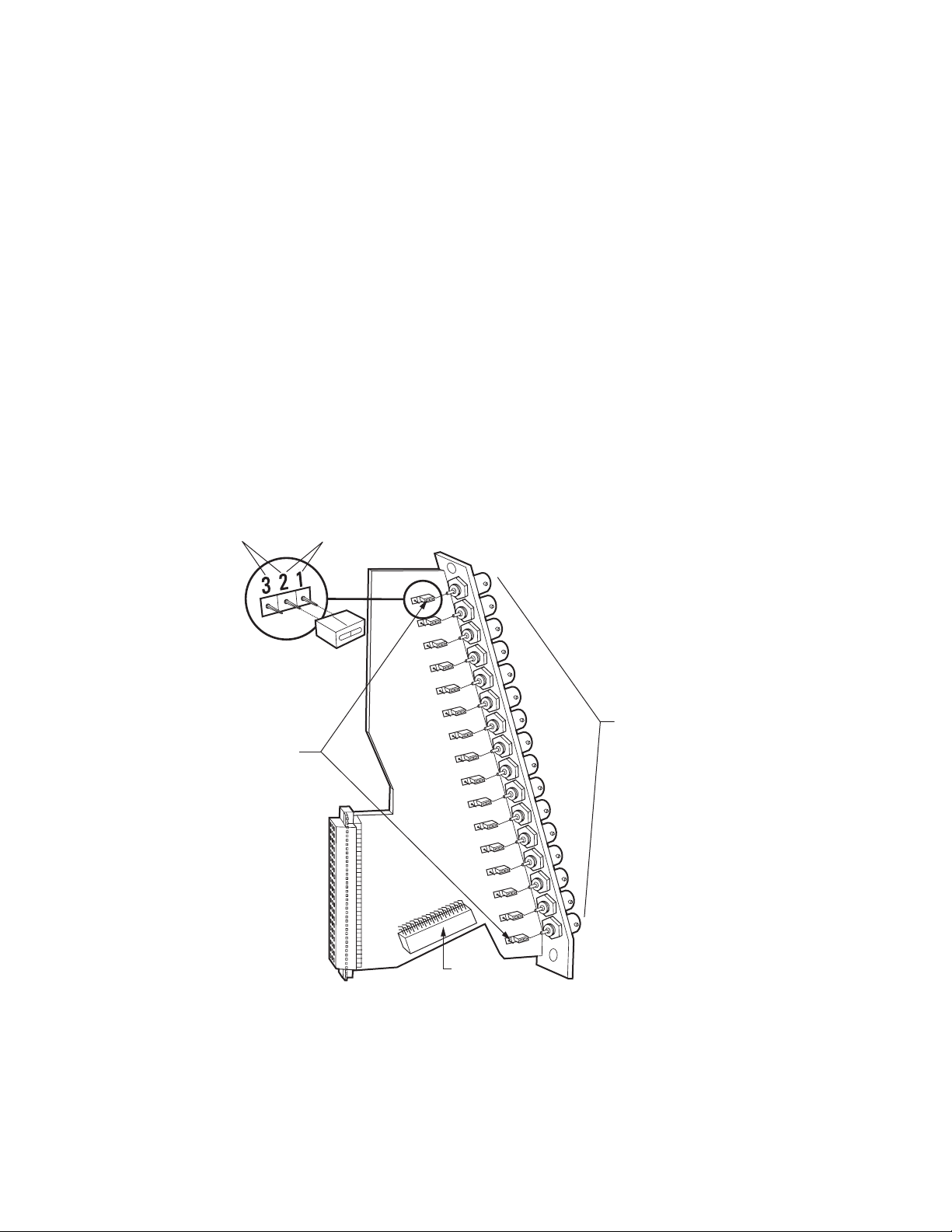
CM9760-VMC Card Guidelines
The following guidelines apply to the CM9760-VMC card:
• The CM9760-VMC card must be installed into slot 17 in the front of the matrix bay. The matrix bay is shipped from the factory with the card
installed in the unit according to the system order.
• The CM9760-VMC card connects to the CM9760-RPM card, which is installed into the associated slot in the rear of the matrix bay.
For information about the CM9760-RPM card, refer to the CM9760-RPM Rear Panel Output Card section.
• S2 DIP switch and X55 and JP2 jumpers are configured properly according to your system order. If you install a new CM9760-VMC card, you
must configure the DIP switch and jumpers as required for your system.
REAR PANEL CARDS
The matrix bay accommodates the following cards, which are installed into the rear of the matrix bay:
• CM9760-RPC: BNC card for video input connections
• CM9760-RPL: Double-wide BNC card for single-bay looping of video inputs
• CM9760-RPM: BNC card for video output connections
• CM9760-DFC: Downframe card with 32-pin connectors (non-looping)
• CM9760-DFL: Downframe looping BNC card
CM9760-RPC REAR PANEL INPUT CARD
The CM9760-RPC rear panel input card (refer to Figure 50) provides 16 BNCs that connect to video input sources such as cameras.
The CM9760-RPC card passes up to 16 external video signals to the CM9760-VCC video input card.
UNTERMINATED TERMINATED
16 VIDEO
INPUT BNCs
JP1-JP16
DOWNFRAME
CONNECTOR
Figure 50. CM9760-RPC Rear Panel Input Card
C1572M (9/05) 95
Page 96

As illustrated in Figure 50, the CM9760-RPC card includes the following:
• BNC Connectors (16): Provide the physical connection point for coaxial cable
• Termination Jumpers JP1-JP16: Determine whether video is to be terminated (jumper positions 1 and 2) or unterminated (jumper
positions 2 and 3):
– In a single-bay configuration (up to 256 cameras and 16 monitors), the setting of the jumpers depends on whether video is to be looped
to another device (for example, a DVR, VCR, or matrix switcher):
• When looping is not required, the jumpers must be set in the terminated position (default position).
• When looping is required, the jumpers must be set in the unterminated position.
– In multiple-bay configurations, the jumpers must be set in the unterminated position.
The jumpers are set in the appropriate position when your system is configured at the factory. However, if you change your system—for
example, add or replace a card—you may need to change the termination.
• Downframe Connector: Sixteen-pin connector that connects to a downframed bay by means of a downframe cable.
CM9760-RPC Card Guidelines
The following guidelines apply to the CM9760-RPC card:
• The CM9760-RPC card connects to a CM9760-VCC video input card, which is installed into the front of the matrix bay. Up to 16 CM9760RPC cards can be inserted into 16 possible slot positions that are associated with the slot positions of the corresponding CM9760-VCC
cards.
• The CM9760-RPC card must be installed before the associated CM9760-VCC video input card is installed into the front of the matrix bay.
• When installing a new card, termination jumpers must be set in the proper position: terminated or unterminated.
CM9760-RPL REAR PANEL LOOPING CARD
The CM9760-RPL rear panel looping card (refer to Figure 51) allows the looping of video. The card contains 16 pairs of BNC connectors that loop
video from video input sources such as cameras to video output devices such as DVRs, VCRs, and matrix switchers. Because of the two rows of
BNC connectors, the CM9760-RPL card requires two slot positions in the matrix bay. The CM9760-RPL card connects to one CM9760-VCC video
input card.
When a maximum of 128 video inputs is required in a system that also requires looping, up to eight CM9760-RPL cards can be used in a
CM9760-MXB.
96 C1572M (9/05)
Page 97

UNTERMINATED
TERMINATED
IN
OUT
16 BNC PAIRS
JP1-JP16
Figure 51. CM9760-RPL Rear Panel Looping Card
As illustrated in Figure 51, the CM9760-RPL card includes the following:
• BNC Connectors (16 pairs): Provide the physical connection point for coaxial cable. For each pair of BNC connectors, one connector
connects to a video source and the other connector connects to the video output device to which the video is looped.
• Termination Jumpers JP1-JP16: Determine whether video is to be terminated (jumper positions 1 and 2) or unterminated (jumper positions
2 and 3):
– When looping functions are required, the termination jumpers must be set in the unterminated position.
– When looping functions are not required, the jumpers must be set in the terminated position.
The jumpers are set in the appropriate position when your system is configured at the factory. However, if you change your system—for
example, add or replace a card—you may need to change the termination.
• Downframe Connector: Sixteen-pin connector that connects to a downframed bay by means of a downframe cable.
CM9760-RPL Card Guidelines
The following guidelines apply to the CM9760-RPL card:
• The CM9760-RPL card connects to a CM9760-VCC video input card, which is installed into the front of the matrix bay.
• The CM9760-RPL card must be installed before the associated CM9760-VCC video input card is installed into the front of the matrix bay.
• In a bay that is to be fully populated with CM9760-RPL cards, note the following:
– The cards must be installed into odd slot positions only. The corresponding CM9760-VCC cards must also occupy odd slot positions.
– The maximum number of video inputs in a matrix bay that is fully populated with CM9760-RPL cards is 128.
• When installing a new card, termination jumpers must be set in the proper position: terminated or unterminated.
C1572M (9/05) 97
Page 98

CM9760-RPM REAR PANEL OUTPUT CARD
The CM9760-RPM rear panel output card (refer to Figure 52) passes up to 16 video signals from the CM9760-VMC video output card to video
output devices such as monitors, VCRs, and matrix switchers. The CM9760-RPM card provides 16 BNCs that connect to video output devices.
UNTERMINATED TERMINATED
16 VIDEO
OUTPUT
JP1-JP16
BNCs
SIDEFRAME
CONNECTOR
Figure 52. CM9760-RPM Rear Panel Output Card
As illustrated in Figure 52, the CM9760-RPM card includes the following:
• BNC Connectors (16): Provide the physical connection point for coaxial cable
• Termination Jumpers JP1-JP16: Allow video to be terminated (jumper positions 1 and 2) or unterminated (jumper positions 2 and 3).
Note that the termination jumpers on the CM9760-RPM card must always be set in the unterminated position. You must terminate the
video signal at the output device, for example, a monitor or VCR. If you are looping to other devices, terminate the last device only.
• Sideframe Connector: Sixteen-pin connector that connects to a coaxial ribbon cable in a sideframe configuration. A coaxial ribbon cable can
be used instead of coaxial cable connections to the BNC connectors on the CM9760-RPM card. For additional information, refer to the
Sideframing section.
CM9760-RPM Card Guidelines
The following guidelines apply to the CM9760-RPM card:
• The CM9760-RPM card must always be installed into the leftmost slot on the rear of the matrix bay. The leftmost slot provides the
connection point to the CM9760-VMC video output card, which is always inserted into slot 17 in the front of the matrix bay.
• The CM9760-RPM must be installed before the CM9760-VMC video output card is installed into the front of the matrix bay.
• Termination jumpers must always be set in the unterminated position.
98 C1572M (9/05)
Page 99

CM9760-DFC REAR PANEL DOWNFRAME CARD
3
2
1
The CM9760-DFC rear panel card (refer to Figure 53) is used in a downframe configuration. The card is installed in every bay between the first
and last bay to connect the associated intermediate bays. The card can also be used in the last bay if looping is not required.
NOTE: Unlike the CM9760-DFL downframe card, the CM9760-DFC downframe card does not provide the ability to loop out video.
The CM9760-DFC card connects to a CM9760-VCC video input card, which is installed into the front of the matrix bay.
A downframe cable is supplied with the CM9760-DFC card. For additional information about downframing, refer to the Downframing section.
INPUT
FROM BAY ABOVE
UNTERMINATED
TERMINATED
JP
1
JP
16
OUTPUT
TO BAY BELOW
Figure 53. CM9760-DFC Downframe Card
As illustrated in Figure 53, the CM9760-DFC card includes the following:
• Termination Jumpers JP1-JP16: Allow video to be terminated (jumper positions 1 and 2) or unterminated (jumper positions 2 and 3):
– When CM9760-DFC cards are used in intermediate bays, termination jumpers must be set in the unterminated position.
– When CM9760-DFC cards are used in the last bay, termination jumpers must be set in the terminated position.
Termination jumpers are set in the appropriate position when your system is configured at the factory. However, if you change your
system—for example, add or replace a card—you may need to change the termination.
• Input Connector: Thirty-two pin male connector that connects to a downframe cable, which then connects to the rear panel card in the bay
above.
• Output Connector: Thirty-two pin male connector that connects to a downframe cable, which then connects to the rear panel card in the bay
below.
CM9760-DFC Card Guidelines
The following guidelines apply to the CM9760-DFC card:
• Within each bay in a downframe configuration, up to 16 CM9760-DFC cards can be inserted into 16 possible slot positions that are
associated with the slot positions of the corresponding CM9760-VCC cards.
• The CM9760-DFC must be installed before the associated CM9760-VCC video input card is installed into the front of the matrix bay.
• When installing a new card, termination jumpers must be set in the proper position: terminated or unterminated.
C1572M (9/05) 99
Page 100

CM9760-DFL REAR PANEL DOWNFRAME LOOPING CARD
The CM9760-DFL rear panel card (refer to Figure 54) is used in the last CM9760-MXB(-X) or CM9760-MXBL bay in a downframe configuration.
The CM9760-DFL card provides the capability to loop out video—the card provides 16 BNCs that can connect to video output devices such as
monitors, VCRs, and matrix switchers. Note, however, that the card can be used in the CM9760-MXB(-X) to increase the number of available
video output devices regardless of whether looping is required. When used in the CM9760-MXB(-X), the CM9760-DFL card connects to a
CM9760-VCC video input card, which is installed into the front of the matrix bay.
The CM9760-DFL card is the only card that is used in the CM9760-MXBL, which is an unpowered downframed matrix bay that contains 16 DFL
card slots for supporting up to 256 video loop-out connections.
A downframe cable is supplied with the CM9760-DFL card. For detailed information about downframing using the CM9760-DFL card, refer to the
Downframing section and to the Downframing to the CM9760-MXBL section as appropriate.
UNTERMINATED TERMINATED
16 VIDEO
INPUT BNCs
JP1-JP16
DOWNFRAME
CONNECTOR
Figure 54. CM9760-DFL Downframe Looping Card
As illustrated in Figure 54, the CM9760-DFL card includes the following:
• BNC Connectors (16): Provide the physical connection point for coaxial cable
• Termination Jumpers JP1-JP16: Allow video to be terminated (jumper positions 1 and 2) or unterminated (jumper positions 2 and 3):
– When looping to another device is required, termination jumpers must be set in the unterminated position. Termination must occur at
the final device.
– When looping is not required, termination jumpers must be set in the terminated position.
The jumpers are set in the appropriate position when your system is configured at the factory. However, if you change your system—for
example, add or replace a card—you may need to change the termination.
• Downframe Connector: Sixteen-pin connector that connects to downframe cable
100 C1572M (9/05)
 Loading...