

Pelco NET6500 user manual

User Manual
NET6500 IP ENCODER 2 Series

© 2022, Motorola Solutions, Inc. All rights reserved. MOTOROLA, MOTO, MOTOROLA SOLUTIONS, and the Stylized M Logo are
trademarks or registered trademarks of Motorola Trademark Holdings, LLC and are used under license. Pelco, the Pelco logo, and
other trademarks associated with Pelco products referred to in this publication are trademarks of Pelco, Inc. or its affi liates. All other
product names and services are the property of their respective companies.

Content
OVERVIEW
4
NSTALLATION
8
WEB VIEWER
14
4 Safety Instruction
5 Key Features
6 What's included
7 Rear Panel
8 Basic Layout
9 Connecting to an external device
14 What is the Web Viewer?
16 Live
21 Setup
APPENDIX
37
37 Troubleshooting (FAQ)
38 Open Software Licensing Agreement

Overview
Safety Instruction
This product was tested with a UPS to satisfy EN 61000-4-11 test conditions (voltage dips and short interruptions test) under the EN
501 30-4: 2011 stand a r d.
The Company shall not have any responsibility for any accident or damage that may incur during the use of the product. For your
safety, we provide a few instructions about installation, manipulation, cleaning, assembly/disassembly of the product as below. So
please read carefully and comply with the instructions.
Before installation
Comply with the following instructions to prevent a fi re, explosion, system failure or electric shock.
Remove the power supply module before proceeding.
~
Check the input voltage (AC100V–AC240V) to the power supply module before connecting it.
~
Keep the product away from humidity.
~
Ensure that all devices connected to the product should be properly earth-grounded.
~
In operation mode
Comply with the following instructions to prevent a fi re, explosion, system failure or electric shock.
If you need to open the cover, consult with a service person who could help you do what you want to do.
~
Do not connect multiple devices to a single power socket.
~
Keep the product away from dust or too much combustible substances (ex: propane gas).
~
Do not touch it with wet hand.
~
Do not insert a conductor in the vent of the ventilation system.
~
Do not apply excessive force to unplug the power cord.
~
4 | Overview
Disassembly & Cleaning
When cleaning on the surface, use a dry cloth.
~
Do not wipe the product using water, paint thinner or organic solvents.
~
Do never dismantle, repair or modify the product by your own.
~
During installation
To prevent an accident or physical injury and to operate ENCODER properly, please comply with the
followings:
Secure at least 18 centimeter of distance between cooling fan and wall for a proper ventilation.
~
Install the product on a fl at surface.
~
Keep it away from direct sunlight or excessive temperature.
~
While in use
Do not apply force to or shake it while using it.
~
Do not move, throw away or put excessive force to it.
~

Key Features
This product can monitor quality image data in real time after receiving audio and video inputs from the 2MP, 3MP, 4MP, 5MP, 8MP
camera for up to 4/16 channels.
It also provides transferring video and audio data to the networked external devices, which allows remote monitoring environment f
computers.
Up to 4/16 channels of 8MP camera video can be displayed in real time
~
Supports High Profi le CODEC
~
H.264 - HP:(Baseline, Main, High profi le),
H.265 - HP:(Main profi le), MJPEG CODEC
Supports dual streaming for remote access service
~
Supports remote access using the web browser
~
Overview
or
English | 5

Overview
What's included
4-Channel Rack Mount 16-Channel Rack Mount
Power adapter x1
(4CH and 16CH)
Screws (For fi xing Cable Clamp)
4CH
Terminal Block 5P (2EA)
Power Cable
(16CH)
Cable Clamp (For fi xing Power Cable)
16CH
Terminal Block 8P (2EA), 5P (2EA)
6 | Overview
Product Insert Black Rack Mount Screw (8EA) Silver Screw (4EA)

Rear Panel
4 CH
16 CH
1234567
No. Name Description
1
2
VIDEO IN Video input terminal for cameras.
AUDIO IN Port for audio input.
91011
8
VIDEO IN
12 453
1231 3
4
24
VIDEO IN AUDIO IN AUDIO OUT
SPOT
OUT
+'021,725
789 10
12453
1213141516
13
24
AUDIO IN
AUDIO OUT
SPOT
OUT
+'021,725
789 10
9*$
9*$
(7+(51(7
(7+(51(7
ALARM IN
Overview
6
RS485
D-
D+
IN1
IN3
GND
'&9
RELAY
NC
NO
IN4
IN2
COM
6
D-
D+
IN1
IN7
IN3
IN5
IN9
IN11
IN13
IN15
GND
GND
GND
'&9
ALARM IN
RS485
ALARM IN
RELAY
NC
NO
IN6
IN2
IN4
IN8
IN10
IN12
IN14
GND
IN16
GND
COM
3
4
5
6
7
8
9
10
SPOT OUT Exclusive port for SPOT output only. (Connect to a TV monitor.)
VGA VGA monitor video output port.
RS485 Ports for communication with external devices such as PTZ camera and system keyboard.
RELAY Relay Terminal output port.
ALARM IN Alarm input signal port.
CABLE CLAMP Used to secure cables.
AUDIO OUT Port for speaker connection.
HD MONITOR HD monitor video output port.
ETHERNET Network port for connection to the Internet, router or hub.
DC 12 Power input port. Connect to a 12V adaptor.
English | 7

Basic Layout
Camera
MIC
SPOT
MONITOR
HD
MONITOR
Speaker
MONITOR
VGA
IP Router
or HUB
Installation
IN1
IN3
GND
IN5
IN7
GND
D+
D-
IN9
IN11
ALARM IN
GND
IN13
IN15
ALARM IN
IN2
IN4
RELAY RS485
GND
IN6
IN8
NO
COM
NC
IN10
IN12
GND
IN14
IN16
Sensor
DC 12V
Power
Alarm
Alarm
Control
Devices
it is recommended to consult an authorized installer when installing the ENCODER.
Since the cable quality may aff ect directly to the video quality depending on the distance between the camera and ENCODER,
8 | Installation

Connecting to an e xterna l device
A
N
A
N
S
85
Power Connection
Plug the provided DC 12V adaptor in the rear power port of the ENCODER.
D-
IN9
D+
IN7
IN5
IN1
IN3
GND
GND
ALARM IN
LARM I
Power adaptor
For stable operation of the product, it is recommended to use the provided adapter
•
(Do not use arbitrary adapters).
Arrange up the cables and be careful not to peel off the cable coating.
•
Do not place the power cord under the carpet or rug. The power cord is usually earth-grounded. However, even if it's not earth-grounded, do not
•
modify it on your own for earth-grounding.
Do not insert multiple devices in a single power socket. Otherwise, it may cause a power overload.
•
The product is equipped with an adapter for power connection. Connect it correctly so it won't come loose.
•
4
ELAY R
RELAY RS485
NC
NO
IN8
IN4
IN6
IN2
IN10
GND
COM
Installation
IN11
IN13
IN15
GND
ALARM IN
LARM I
IN16
IN14
IN12
GND
English
|
9

Installation
ALARM IN
IN9
IN11
GND
IN13
IN15
IN10
IN12
GND
IN14
IN16
ALARM IN
RELAY RS485
NC
COM
NO
IN8
IN6
GND
IN4
IN2
D-
D+
IN7
GND
IN5
GND
IN3
IN1
Alarm I/O Connection
To connect the alarm input signal
Connect the signal line of an alarm input device such as sensor to the rear [ALARM IN] port.
Insert one end of alarm signal cable through the [IN1] ~ [IN16] terminal hole below the screw hole, and then fasten the screw.
1.
Push the Alarm In and [GND] terminals’ bottom side with a sharp tipped tool such as screw driver.
2.
While pushing, insert one end of alarm signal cable into the hole of Alarm In terminal.
3.
While pushing, insert one end of ground cable into the hole of [GND] terminal.
4.
To check proper insertion of cable, stop pushing and gently pull the cable and test whether it disconnects.
5.
To disconnect a cable, push the bottom side of the terminal and pull out the cable.
To connect the alarm output signal
Connect the signal cable of the alarm output device to the [RELAY] terminal on the product’s rear side.
Push the [NO]/[NC]/[COM] terminal’s bottom side with a sharp tipped tool such as screw driver.
1.
While pushing, insert one end of alarm signal cable into the desired terminal of [NO] or [NC].
2.
NO(Normal Open) : Normally Open but switching to Close if an alarm out occurs.
COM : Insert the grounding wire.
NC(Normal Close) : Normally Close but switching to Open if an alarm out occurs.
Insert the ground signal wire into the hole of the [COM] port (shown also below the screw), and tighten the screw.
3.
To check proper insertion of cable, stop pushing and gently pull the cable and test whether it disconnects.
4.
To disconnect a cable, push the bottom side of the terminal and pull out the cable.
10 | Installation

Communi ca t io n Port
ALARM IN
RELAY RS485
NC
COM
NO
IN8
IN6
GND
IN4
IN2
D-
D+
IN7
GND
IN5
GND
IN3
IN1
RS-485 Connection
Connect a PTZ Camera or Keyboard Controller.
After connecting the control device, be sure to match the connection settings between ENCODER and device.
Make communication settings in <Control Device>. (page 32)
Use the signal wire to make connection between [D+] of the terminal block plug and [D+] of the keyboard controller.
1.
Make connection between [D-] of the terminal block plug and [D-] of the keyboard controller.
2.
Make connection between [GND] of the terminal block plug and [GND] of the keyboard controller.
3.
* For RS-485 connection, refer to the user manual of the keyboard controller.
Audio Device Connection
You can connect an audio output device such as speaker amplifi er .
Connect the audio input device such as microphone to the rear Audio In port, connect the audio output device such as speaker
amplifi er to the Audio Out port.
Installation
English
|
11

Installation
ALARM IN
IN9
IN11
GND
IN13
IN15
IN10
IN12
GND
IN14
IN16
ALARM IN
RELAY RS485
NC
COM
NO
IN8
IN6
GND
IN4
IN2
D-
D+
IN7
GND
IN5
GND
IN3
IN1
A
N
Y
[
Network Connection
PC connection in the local network
You can connect ENCODER to a PC in the same network and control or manipulate it on the PC monitor.
Camera
Broadband router
or hub
Local PC
Local PC
Connect the [ETHERNET] port in the rear panel to the router or hub.
1.
Connect the local PC to the router or hub.
2.
ND
IN11
IN13
IN15
IN15
GND
ALARM IN
LARM I
ND
N16
IN16
IN14
IN12
GND
Broadband router
[~huylzl{w~y Z Y X
Local PC
Enter the address in the Web browser of your PC in the format of: “http://IP address:Web service port”
3.
(Ex : http://192.168.0.23:80) The web service port is set to 80 by default. From the Network Setup screen,
u can change the port number.
yo
or hub
Local PC
* If using the dedicated PC S/W, refer to the user manual of the program.
Enter the user ID and password before logging in. The initial administrator ID is “admin” and the password should be set
4.
when logging in for the fi rst time. Then, you can view the monitoring screen.
12 | Installation
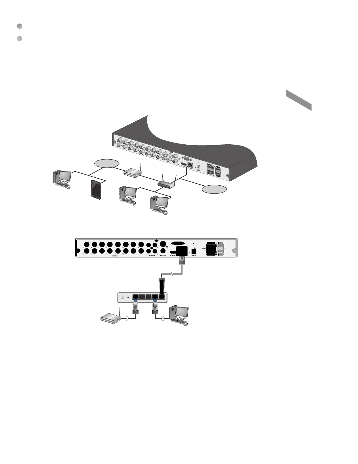
PC connection from a remote network
ALARM IN
IN9
IN11
GND
IN13
IN15
IN10
IN12
GND
IN14
IN16
ALARM IN
RELAY RS485
NC
COM
NO
IN8
IN6
GND
IN4
IN2
D-
D+
IN7
GND
IN5
GND
IN3
IN1
ALARM IN
5
D
You can connect ENCODER to a PC in the same remote network and control or manipulate it on the monitor of the PC or mobile
device.
Internet
ADSL modem
Remote PC
Smart Phone
Connect the [ETHERNET] port in the rear panel to the router.
1.
Local PC
Broadband router
Local PC
Internet
Direct Connection
IN11
IN13
IN15
IN13IN1
GND
ALARM IN
N
N16
N14
IN16
IN12
IN14
GND
Installation
4WANRESETPWR 3 2 1
ADSL modem
Connect the [ETHERNET] port of the router directly to the fi xed IP LAN cable, or connect it to the ADSL modem.
2.
Broadband router
Local PC
English
|
13

Web Viewer
What is the We b Vie w er?
Web Registration Authority is a user-friendly software application that enables you to control the video data in connection with a remote
ENCODER.
System Requirements
The following is the minimum hardware and operating system requirements to run Web RA.
Operating System Windows 7 or higher
Web browsers:
CPU Intel Pentium 4 / 2.0GHz or higher
Memory 512 MB
Display 16-bit 1024 x 768 High Color
Microsoft Edge/Mozilla Firefox 3.6/Google Chrome 4.1/Opera 10
Some web browsers other than Microsoft Edge may not fully function.
Connection
Open a browser and enter the IP address of ENCODER, or type the URL in the address bar.
T o connect to the ENCODER from inside
-
Check the "Network Status" and verify the
<IP ADDRESS> and <WEB SERVICE PORT>
of the ENCODER.
-
Enter the IP address and web service port in the
address bar of the browser.
Ex) http://192.168.1.200:80
T o connect to the ENCODER from outside
Using the IP address
~
-
Check the "Network Status" and verify the <EXTERNAL IP ADDRESS> and <WEB SERVICE PORT> of the ENCODER.
-
If using a fi xed (external) IP, enter the external IP that is specifi ed in the ENCODER in the address bar of the web browser.
Ex) If the internal IP address is set to "http://222.11 2.4.48:80" (192.xxx.xxx.xxx), no acc ess f rom outside is allowed.
Using the URL
~
-
Check the "Network Status" and verify the <DDNS ADDRESS> and <WEB SERVICE PORT> of the ENCODER.
-
Enter the DDNS address and web service port in the address bar of the browser.
* In a router network, you have to set the "Port Forwarding" and "DDNS Setting" to allow access from outside.
* For the necessary settings of the router, refer to the user manual of the router or contact the manufacturer of the router.
Provide the user ID and password.
1.
* The initial administrator ID is "admin" and the password should be set when logging in for the fi rst time.
When the installation is complete, you will see the live screen.
2.

Web Viewer
English
|
15
 Loading...