

Page 1

I N S T A L L A T I O N
KBDKIT Remote Keyboard Wiring Kit
C1922M-C (11/12)
Page 2

Contents
Description. . . . . . . . . . . . . . . . . . . . . . . . . . . . . . . . . . . . . . . . . . . . . . . . . . . . . . . . . . . . . . . . . . . . . . . . . . . . . . . . . . . . . . . . . . . . . . . . . . . . . . . . . . . 3
Models . . . . . . . . . . . . . . . . . . . . . . . . . . . . . . . . . . . . . . . . . . . . . . . . . . . . . . . . . . . . . . . . . . . . . . . . . . . . . . . . . . . . . . . . . . . . . . . . . . . . . . . . . 3
Installing Multiple Remote Keyboards . . . . . . . . . . . . . . . . . . . . . . . . . . . . . . . . . . . . . . . . . . . . . . . . . . . . . . . . . . . . . . . . . . . . . . . . . . . . . . . . . 3
Connecting to the CM6700 Matrix Switcher or the MX4000SVR Multiplexer Server . . . . . . . . . . . . . . . . . . . . . . . . . . . . . . . . . . . . . . . . . . . . 3
Connecting a Remote Keyboard to the MX4000 Multiplexer . . . . . . . . . . . . . . . . . . . . . . . . . . . . . . . . . . . . . . . . . . . . . . . . . . . . . . . . . . . . . . . 4
Direct Mode . . . . . . . . . . . . . . . . . . . . . . . . . . . . . . . . . . . . . . . . . . . . . . . . . . . . . . . . . . . . . . . . . . . . . . . . . . . . . . . . . . . . . . . . . . . . . . . . . . . . . 6
2 C1922M-C (11/12)
Page 3
Description
CM6700 SCU OR MX4000SVR
REMOTE KEYBOARD(S) PORT
WALL
TRANSFORMER
USER SUPPLIED
CABLE (SEE FIGURE 2)
ADDITIONAL
KEYBOARDS
AS NEEDED
KBDKBD
CABLE
KEYBOARD
DATA CABLE
The Remote Keyboard Wiring Kits of the KBDKIT Series are used to connect KBD100, KBD200, or KBD300 keyboards to the CM6700 Matrix
Switcher, or to connect the KBD4000 keyboard to the Genex MX4000SVR Multiplexer Server or Genex™ MX4000 Series Multiplexer. The kits are
also used when installing either the KBD200 or KBD300 for Direct Mode control of Pelco receivers.
MODELS
KBDKIT Remote keyboard wiring kit that includes two RJ-45 wall blocks and a transformer to convert 120 VAC power to 12 VAC
for keyboard power.
KBDKIT-X Remote keyboard wiring kit that includes two RJ-45 wall blocks and a transformer to convert 230 VAC power to 12 VAC
for keyboard power.
Installing Multiple Remote Keyboards
You can connect up to eight KBD100, KBD200, or KBD300 keyboards to the REMOTE KEYBOARD(S) port of the CM6700 Matrix Switcher or up to
four KBD4000 keyboards to the REMOTE KEYBOARD(S) port of the Genex™ MX4000SVR Multiplexer Server.
You can connect one KBD4000 Keyboard to the COM IN receptacle of an MX4000 Series Multiplexer at a remote location at a maximum distance
of 1,219 m (4,000 feet).
NOTES:
• The second RJ-45 wall block is for use with the KBD4000 keyboard and MX4000 multiplexer only (refer to Figure 3 on page 5).
• To install more than one keyboard, you must have a kit for each keyboard.
• Keyboards must be addressed differently when more than one keyboard is used.
CONNECTING TO THE CM6700 MATRIX SWITCHER OR THE MX4000SVR MULTIPLEXER SERVER
1. If the DIP switches on the keyboards have not been set already, refer to your keyboard manual to set the switches.
2. Determine the location of all keyboards. Each keyboard must be located within 7.6 m (25 feet) of where you will install the wall block. Wall
blocks must be within 1.8 m (6 feet) of the nearest electrical outlet to accommodate the transformer.
3. Run the wall block interconnect cable (user-supplied shielded twisted pairs) from the CM6700 or MX4000SVR to the wall block locations.
Wall blocks should be wired in a daisy-chain configuration for best results (refer to Figure 1 on page 3). Communications with the
keyboards, which are connected to the wall blocks, is RS-485. Maximum cable distance from the CM6700 Matrix Switcher or MX4000SVR
Multiplexer Server to the last keyboard in the chain is 1,219 m (4,000 feet).
NOTE: Pelco recommends using shielded twisted pairs cable, such as Belden 9843 or similar cable, that meets or exceeds the basic
requirements for EIA RS-422 or RS-485 applications.
Figure 1. Keyboard Cable Connections
C1922M-C (11/12) 3
Page 4

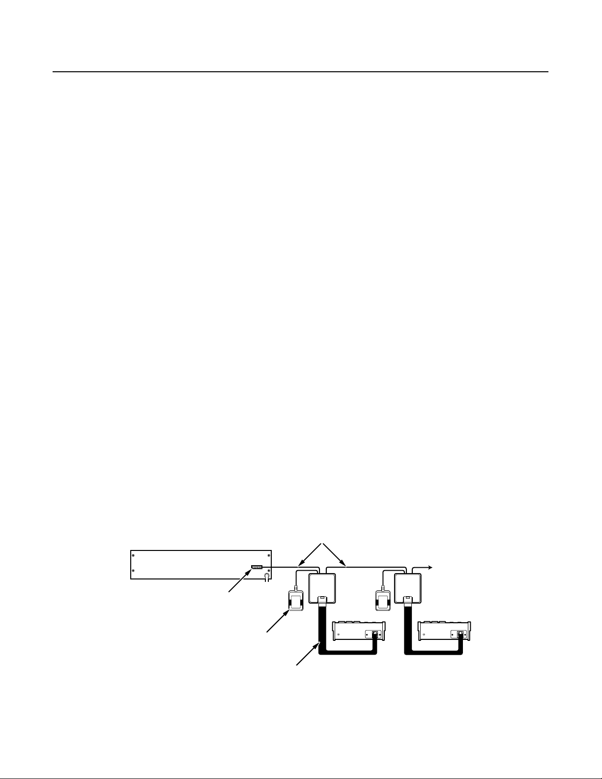
4. Remove the covers from the wall blocks. Wire the connections between the wall blocks and the CM6700 or MX4000SVR (refer to Figure 2).
1
2
3
4 5
6
7
8
T+ T– R– R+
1
2
3
4
5
6
7
8
TX+
TX-
12 V AC
12 V AC
GND
RX-
RX+
1
2
3
4
5
6
7
8
1
2
3
4
5
6
7
8
REMOTE KEYBOARD(S)
WALL BLOCK
TERMINAL ASSIGNMENTS
12 VAC
WALL
TRANSFORMER
12 VAC
WALL
TRANSFORMER
* FOUR MAXIMUM FOR MX4000SVR OR
EIGHT MAXIMUM FOR CM6700 SCU
12 VAC
WALL
TRANSFORMER
USER-SUPPLIED
CABLE
FIRST KBDKIT
WALL BLOCK
TERMINAL TERMINAL TERMINAL
SECOND KBDKIT
WALL BLOCK*
THIRD KBDKIT
WALL BLOCK*
Connect the transformers to terminals 3 and 4 of each wall block. Polarity is unimportant.
4 C1922M-C (11/12)
Figure 2. CM6700 or MX4000SVR Remote Keyboard Wiring
5. Replace the covers on the wall blocks. Secure each wall block to a suitable surface with the double-sided sticky pad that is supplied.
6. Plug each transformer into a power outlet.
7. Connect the data cable that is supplied with each keyboard. Plug one end into the wall block and the other end into the keyboard
receptacle.
Page 5

CONNECTING A REMOTE KEYBOARD TO THE MX4000 MULTIPLEXER
TX– TX+RX+ RX–
8 7 6
5 4 3 2 1
8 7 6
5 4 3 2 1
RX– RX+TX+ TX–
TX+
TX-
AC
AC
GND
RX-
RX+
12 V
12 V
TX+
TX-
GND
RX-
RX+
1
2
3
4
5
6
7
8
1
2
3
4
5
6
7
8
1
2
3
4 5
6
7
8
MX4000 MULTIPLEXER
COM IN RJ-45
KBD4000 KEYBOARD
RJ-45 PORT
25 FT (7.6M) CABLE
SUPPLIED WITH
KEYBOARD
6 FT (1.8M)
CABLE SUPPLIED
WITH MULTIPLEXER
USER-SUPPLIED CABLE
MAXIMUM DISTANCE
OF 4,000 FT (1,219M)
WALL BLOCK
TERMINAL
12 VAC
WALL
TRANSFORMER
WALL BLOCK
TERMINAL ASSIGNMENTS
WALL BLOCK
TERMINAL
1. If the DIP switches on the keyboard have not been set already, refer to the keyboard manual to set the switches.
2. Determine the location of the keyboard. It must be located within 7.6 m (25 feet) of where you will install its wall block (refer to Figure 2).
The wall block for the KBDKIT must be within 1.8 m (6 feet) of the nearest electrical outlet to accommodate the transformer.
Communications with the keyboard, which is connected to the wall block, is RS-485.
3. Determine the location of the multiplexer. It must be located within 1.8 m (6 feet) of where you want to install its wall block (refer to
Figure 3).
4. Run the interconnect cable (user-supplied shielded twisted pairs) from the keyboard wall block to the multiplexer wall block. Maximum
cable distance between the wall blocks is 1,219 m (4,000 feet).
5. Remove the covers from the wall blocks. Connect the cable to the wall blocks (refer to Figure 3). Connect the transformer to terminals 3 and
4 of the keyboard wall block. Polarity is unimportant.
Figure 3. KBD4000 Keyboard and MX4000 Series Multiplexer Wiring
6. e the covers on the wall blocks. Secure each wall block to a suitable surface with the double-sided sticky pad that is supplied.
7. Plug each transformer into a power outlet.
8. Plug one end of the 7.6-meter (25-foot) data cable into the KBD4000 keyboard receptacle and the other end into the wall block.
C1922M-C (11/12) 5
9. Plug one end of the 1.8-meter (6-foot) data cable into the COM IN receptacle on the rear of the multiplexer and the other end into the wall
block.
Page 6

Direct Mode
RX+
TX-
TX+
2
3
4 5
6
7
1 8
RX– GND
GND
KDB200/KBD300
KEYBOARD
DATA CABLE
KBDKIT OR
KBDKIT-X
TWISTED
PAIR
TO RECEIVER/DRIVERS
Using the KBD200 or KBD300 in Direct Mode is a single keyboard installation. Daisy-chaining more than one keyboard is not possible.
To connect the keyboard:
1. If the DIP switches on the keyboard have not been set already, refer to your keyboard manual to set the switches.
2. Determine the location for the keyboard. The keyboard must be located within 7.6 m (25 feet) of where you will install the wall block. The
wall block must be within 1.8 m (6 feet) of the nearest electrical outlet to accommodate the transformer.
3. Remove the cover from the wall block. Wire the connections between the wall block and the receiver/drivers (refer to Figure 4). Up to 16
receiver/drivers can be controlled from the keyboard. Receiver/drivers should be wired in a daisy-chain configuration for best results.
a. Connect RX+ from the first receiver/driver to TX+ (terminal 1) on the wall block.
b. Connect RX– from the first receiver/driver to TX– (terminal 2) on the wall block.
c. Connect the transformer to terminals 3 and 4. Polarity is unimportant.
d. Connect GND from the first receiver/driver to GND (terminal 5) on the wall block.
4. Replace the cover on the wall block. Secure the wall block to a suitable surface with the double-sided sticky pad that is supplied.
5. Plug the transformer into a power outlet.
6. Connect the 7.6-meter (25-foot) data cable that is supplied with the keyboard. Plug one end into the wall block and the other end into the
keyboard receptacle.
Figure 4. Direct Mode Wiring
6 C1922M-C (11/12)
Page 7

PRODUCT WARRANTY AND RETURN INFORMATION
WARRANTY
Pelco will repair or replace, without charge, any merchandise proved defective in
material or workmanship for a period of one year after the date of shipment.
Exceptions to this warranty are as noted below:
• Five years:
– Fiber optic products
– Unshielded Twisted Pair (UTP) transmission products
– CC3701H-2, CC3701H-2X, CC3751H-2, CC3651H-2X, MC3651H-2, and
MC3651H-2X camera models
• Three years:
– FD Series and BU Series analog camera models
– Fixed network cameras and network dome cameras with Sarix® technology
– Sarix thermal imaging products (TI and ESTI Series)
– Fixed analog camera models (C20 Series, CCC1390H Series, C10DN Series,
and C10CH Series)
– EH1500 Series enclosures
– Spectra
– Spectra HD dome products
– Camclosure® IS Series integrated camera systems
– DX Series video recorders (except DX9000 Series which is covered for a
– Endura
– Genex® Series products (multiplexers, server, and keyboard)
– PMCL200/300/400 Series LCD monitors
– PMCL5xxF Series and PMCL5xxNB Series LCD monitors
– PMCL5xxxBL Series LED monitors
• Two years:
– Standard varifocal, fixed focal, and motorized zoom lenses
– DF5/DF8 Series fixed dome products
– Legacy® Series integrated positioning systems
– Spectra III™, Spectra Mini, Spectra Mini IP, Esprit®, ExSite®, ExSite IP, and
– Esprit Ti and TI2500 Series thermal imaging products
– Esprit and WW5700 Series window wiper (excluding wiper blades)
– CM6700/CM6800/CM9700 Series matrix
– Digital Light Processing (DLP®) displays (except lamp and color wheel). The
®
IV products (including Spectra IV IP)
period of one year), DVR5100 Series digital video recorders, Digital Sentry
Series hardware products, DVX Series digital video recorders, and NVR300
Series network video recorders
®
Series distributed network-based video products
PS20 scanners, including when used in continuous motion applications
lamp and color wheel will be covered for a period of 90 days. The air filter is
not covered under warranty.
• Six months:
– All pan and tilts, scanners, or preset lenses used in continuous motion
applications (preset scan, tour, and auto scan modes)
Pelco will warrant all replacement parts and repairs for 90 days from the date of
Pelco shipment. All goods requiring warranty repair shall be sent freight prepaid
to a Pelco designated location. Repairs made necessary by reason of misuse,
alteration, normal wear, or accident are not covered under this warranty.
Pelco assumes no risk and shall be subject to no liability for damages or loss
resulting from the specific use or application made of the Products. Pelco’s liability
for any claim, whether based on breach of contract, negligence, infringement of
any rights of any party or product liability, relating to the Products shall not exceed
the price paid by the Dealer to Pelco for such Products. In no event will Pelco be
liable for any special, incidental, or consequential damages (including loss of use,
loss of profit, and claims of third parties) however caused, whether by the
negligence of Pelco or otherwise.
The above warranty provides the Dealer with specific legal rights. The Dealer may
also have additional rights, which are subject to variation from state to state.
If a warranty repair is required, the Dealer must contact Pelco at (800) 289-9100 or
(559) 292-1981 to obtain a Repair Authorization number (RA), and provide the
®
following information:
1. Model and serial number
2. Date of shipment, P.O. number, sales order number, or Pelco invoice number
3. Details of the defect or problem
If there is a dispute regarding the warranty of a product that does not fall under
the warranty conditions stated above, please include a written explanation with
the product when returned.
Method of return shipment shall be the same or equal to the method by which the
item was received by Pelco.
RETURNS
To expedite parts returned for repair or credit, please call Pelco at (800) 289-9100
or (559) 292-1981 to obtain an authorization number (CA number if returned for
credit, and RA number if returned for repair) and designated return location.
All merchandise returned for credit may be subject to a 20 percent restocking and
refurbishing charge.
Goods returned for repair or credit should be clearly identified with the assigned
CA or RA number and freight should be prepaid.
Revised 10-9-12
The materials used in the manufacture of this document and its components are compliant to the requirements of Directive 2002/95/EC.
This equipment contains electrical or electronic components that must be recycled properly to comply with Directive 2002/96/EC of the European Union
regarding the disposal of waste electrical and electronic equipment (WEEE). Contact your local dealer for procedures for recycling this equipment.
REVISION HISTORY
Manual # Date Comments
C1922M 5/98 Original version.
C1922M-A 1/99 Added MX4000 Multiplexer.
C1922M-B 4/99 Added a second RJ-45 wall block for use with the KBD4000 keyboard and MX4000 multiplexer.
C1922M-C 11/12 Revised the ground (GND) connection instructions for direct mode wiring. Also updated the document to reflect the current template.
Pelco, the Pelco logo, and other trademarks associated with Pelco products referred to in this publication are trademarks of Pelco, Inc. or its affiliates. © Copyright 2012, Pelco, Inc.
ONVIF and the ONVIF logo are trademarks of ONVIF Inc. All other product names and services are the property of their respective companies. All rights reserved.
Product specifications and availability are subject to change without notice.
Page 8

Pelco by Schneider Electric 3500 Pelco Way Clovis, California 93612-5699 United States
USA & Canada Tel (800) 289-9100 Fax (800) 289-9150
International Tel +1 (559) 292-1981 Fax +1 (559) 348-1120
www.pelco.com www.pelco.com/community
 Loading...