

Page 1
INSTALLATION
IE-S Surface Mount Adapter
C2240M (11/09)
Page 2

Contents
Important Safety Instructions. . . . . . . . . . . . . . . . . . . . . . . . . . . . . . . . . . . . . . . . . . . . . . . . . . . . . . . . . . . . . 3
Description . . . . . . . . . . . . . . . . . . . . . . . . . . . . . . . . . . . . . . . . . . . . . . . . . . . . . . . . . . . . . . . . . . . . . . . . . . . 4
Parts List. . . . . . . . . . . . . . . . . . . . . . . . . . . . . . . . . . . . . . . . . . . . . . . . . . . . . . . . . . . . . . . . . . . . . . . . 4
Installation . . . . . . . . . . . . . . . . . . . . . . . . . . . . . . . . . . . . . . . . . . . . . . . . . . . . . . . . . . . . . . . . . . . . . . . . . . . 5
Basic Surface Installation . . . . . . . . . . . . . . . . . . . . . . . . . . . . . . . . . . . . . . . . . . . . . . . . . . . . . . . . . . 5
Side Conduit Installation . . . . . . . . . . . . . . . . . . . . . . . . . . . . . . . . . . . . . . . . . . . . . . . . . . . . . . . . . . . 6
Lens and Back Box . . . . . . . . . . . . . . . . . . . . . . . . . . . . . . . . . . . . . . . . . . . . . . . . . . . . . . . . . . . . . . . . 7
Specifications. . . . . . . . . . . . . . . . . . . . . . . . . . . . . . . . . . . . . . . . . . . . . . . . . . . . . . . . . . . . . . . . . . . . . . . . 10
2 C2240M (11/09)
Page 3

Important Safety Instructions
1. Read these instructions.
2. Keep these instructions.
3. Heed all warnings.
4. Follow all instructions.
5. Only use attachments/accessories specified by the manufacturer.
6. Installation should be done only by qualified personnel and conform to all local codes.
7. Use only installation methods and materials capable of supporting four times the maximum
specified load.
8. Only use replacement parts recommended by Pelco.
C2240M (11/09) 3
Page 4

Description
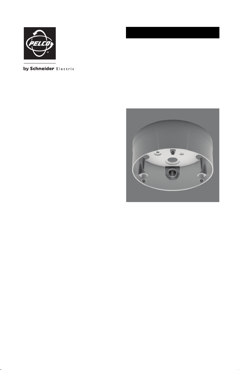
The IE-S is a surface mount adapter specifically designed for IE and IEE Series network dome cameras. The
surface adapter modifies the network dome camera so it can be mounted directly to a ceiling.
You can install the IE-S surface mount adapter using one of the following methods:
• Pull the dome camera wiring through the top of the surface mount adapter (refer to Basic Surface
Installation on page 5).
• Pull the dome camera wiring through the side conduit of the surface mount adapter (refer to Side
Conduit Installation on page 6).
PARTS LIST
Remove all of the contents from the shipping box.
Qty
Description
1
IE-S surface mount adapter
1
Tube of Loctite
3
10-32 Phillips pan head screws
1
Installation manual
Installation tools and the following parts are needed but not supplied:
Qty
Description
1
IE or IEE Series network dome camera
1
Lens (use either a megapixel or standard auto iris lens, depending on camera model)
1
IX-SC service cable
1
Mounting hardware
®
4 C2240M (11/09)
Page 5
Installation
BASIC SURFACE INSTALLATION
1. Use the surface mount adapter as a template to mark the holes for the mounting hardware, cable,
and wiring on the mounting surface.
2. Prepare the mounting surface as follows:
• Standard ceiling: When mounting the surface mount adapter to a standard ceiling, use
either 8-32 toggle bolts (not supplied) or #8 x 3.50-inch self-tapping screws (not supplied).
• Concrete ceiling: When mounting the surface mount adapter to a concrete system, use
8-32 studs and nuts (not supplied). Cut out the hole for the cable and wiring. Pull the cable and
wires through the mounting surface and then through the surface mount adapter. Terminate
all wires (if not already terminated).
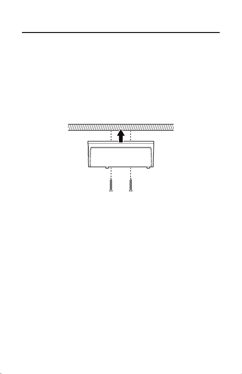
3. Attach the surface mount adapter to the mounting surface (hardware not supplied). Use stainless
steel hardware when installing the system outdoors.
Figure 1. Installing Surface Mount Adapter to Surface
4. Install the lens and back box (refer to Lens and Back Box on page 7).
C2240M (11/09) 5
Page 6
SIDE CONDUIT INSTALLATION
1. Use the surface mount adapter as a template to mark the holes for the mounting hardware on the
mounting surface.
2. Prepare the mounting surface as follows:
• Standard ceiling: When mounting the surface mount adapter to a standard ceiling, use
either 8-32 toggle bolts (not supplied) or #8 x 3.50-inch self-tapping screws (not supplied).
• Concrete ceiling: When mounting the surface mount adapter to a concrete system, use
8-32 studs and nuts (not supplied).
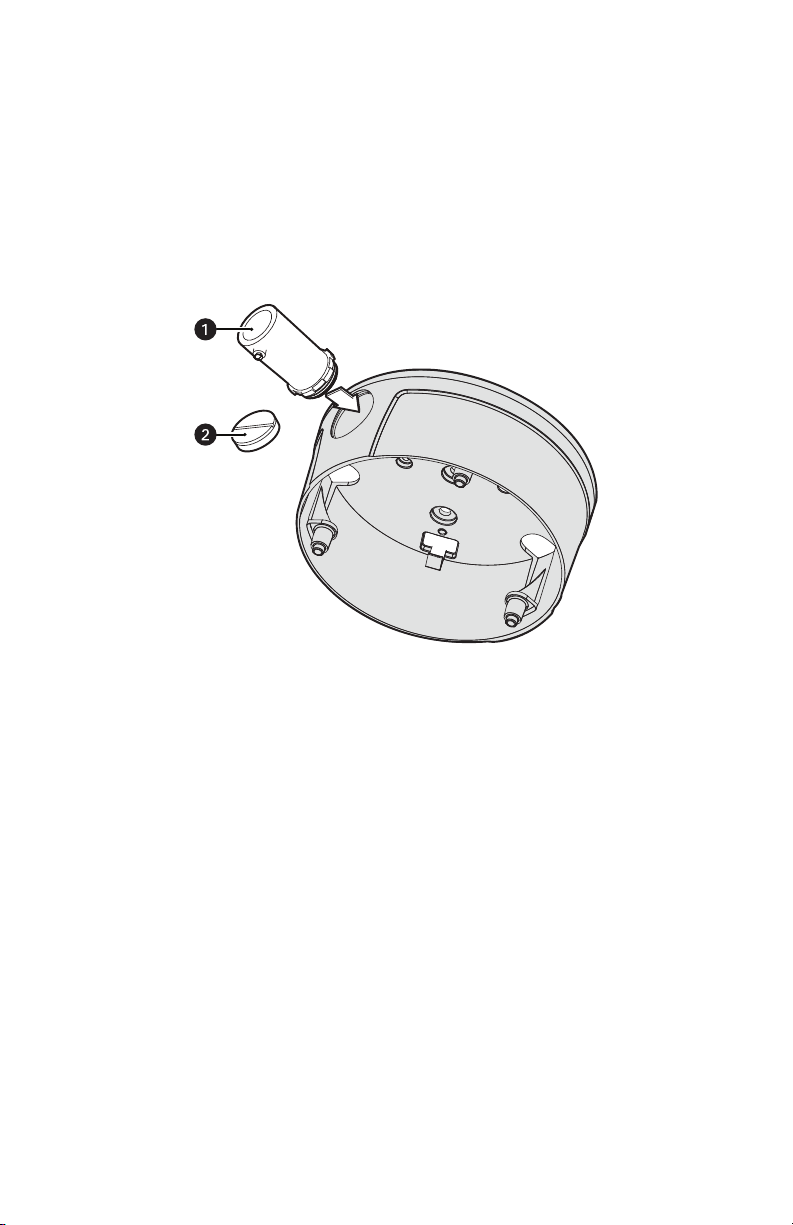
3. Remove the conduit plug from the surface mount adapter. Install a 0.75-inch or 25 mm threaded
conduit connector (not supplied) into the conduit hole in the surface mount adapter.
Figure 2. Installing Conduit Connector
ì
0.75-inch or 25 mm Conduit Connector (not supplied)
î
Conduit Plug
4. Pull the cable and wires through the conduit and then through the surface mount adapter. Terminate
all wires (if not already terminated).
5. Attach the surface mount adapter to the mounting surface (hardware not supplied). Use stainless
steel hardware when installing the system outdoors.
6. Install the lens and back box (refer to Lens and Back Box on page 7).
6 C2240M (11/09)
Page 7
LENS AND BACK BOX
Pin DC (AID) Auto Iris Lens
1 Control coil negative (–)
2 Control coil positive (+)
3 Drive coil positive (+)
4 Drive coil negative (–)
1
2
3
4
5
6
7
8
8 7 6 5
4 3
2 1
1
2
3
4
5
6
7
8
1
2
3
4
5
6
7
8
8 7 6 5 4 3 2 1
8
8
1
1
Pin Function
1TX+
2TX–
3RX+
4PoE 1-2
5PoE 1-2
6RX–
7PoE 3-4
8PoE 3-4
NOTE: Megapixel lenses are designed and tested to deliver optimal image quality to megapixel cameras.
A standard definition lens installed on a megapixel camera will limit the resolution of the camera and
create poor image quality.
1. Install the lens on the IE or IEE Series back box:
a. Remove the cover from the lens mount.
b. Screw the lens onto the lens mount. Be careful to prevent dust from entering the space
between the lens and the imager. If necessary, use clean, compressed air to remove any
foreign matter (refer to the instructions shipped with the lens).
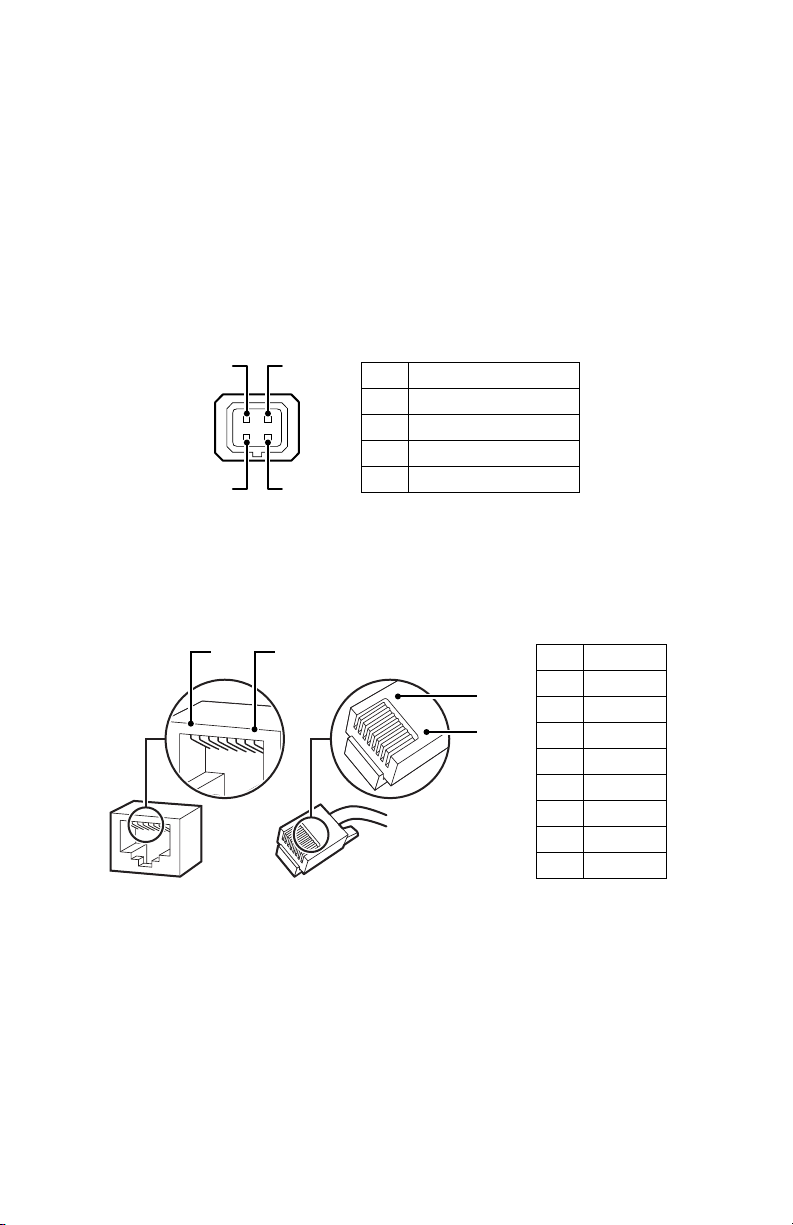
c. Connect the auto iris lens to the 4-pin connector located on the side of the camera. Refer to
Figure 3 for pin designation and iris drive connector information.
3
4
12
Figure 3. Lens Pin Connections
2. Connect the network cable to the RJ-45 network port on the side of the back box. If the network has
no Power over Ethernet (PoE), connect a 24 VAC Class 2 power supply to the 24 VAC power
connector.
Figure 4. RJ-45 Pin Descriptions
C2240M (11/09) 7
Page 8

3. Connect the wiring for the alarms and relays.
Table A. Alarm and Relay Wire Descriptions
Wire Color Description
Brown Line In +
White/Brown Line In –
Orange Line Out +
White/Orange Line Out –
Green/White Relay Return
Green Relay Out
Blue Alarm In
Blue/White Alarm Return
4. Connect the 24 VAC power wires to operate the heater inside the dome. If PoE is not available, 24
VAC also supplies power to the camera. Refer to Table B for wire descriptions and Table C for wiring
distances.
Table B. 24 VAC Wire Descriptions
Wire Color Description
Red 24 VAC +
Black 24 VAC –
Table C. 24 VAC Wiring Distances
AC/DC Total
VA/ Total
Watts
20 AWG 18 AWG 16 AWG 14 AWG
Wire Gauge
23 VA/15 W 123 ft (38 m) 196 ft (60 m) 311 ft (95 m) 495 ft (151 m)
75 VA/65 W 39 ft (12 m) 62 ft (19 m) 98 ft (30 m) 156 ft (48 m)
NOTES:
• Power consumption for the IE and IEE Series cameras is 60 VA with the heater running.
• Use a 24 VAC transformer with a minimum of 100 VA per dome.
• If you are operating the camera using 24 VAC and you are wiring more than one camera to the same
transformer, connect one side of the transformer to the red wire (24 VAC+) and connect the other
side of the transformer to the black wire (24 VAC–). Failure to connect all modules identically might
introduce video noise for some installations.
8 C2240M (11/09)
Page 9

5. Install the back box:
a. Install the back box in the surface mount adapter. Line up the back box screws with the three
mounting screw holes on the surface mount adapter.
b. Install the machine screws (supplied).
c. Tighten the machine screws completely to secure the back box to the surface mount adapter.
Figure 5. Installing the Back Box
6. Apply power to the camera. The camera will complete a configuration sequence: the green LED
flashes five times per second for approximately two minutes and then turns solid after the sequence
is complete.
NOTE: If the camera is not connected to a Dynamic Host Configuration Protocol (DHCP) server and
DHCP is enabled, the configuration sequence might take up to five minutes to complete.
7. To complete the installation, refer to the IE Series Installation/Operation manual or the IEE Series
Installation/Operation manual.
C2240M (11/09) 9
Page 10

Specifications
3.00
(7.60)
7.69
(19.50)
REVISION HISTORY
Manual # Date Comments
C2240M 11/09 Original version.
Pelco, the Pelco logo, Camclosure, Digital Sentry, Endura, Esprit, ExSite, Gene x, Intelli-M, Legacy, and Spectra are registered trademarks of Pelco, Inc.
Spectra III is a trademark of Pelco, Inc.
DLP is a registered trademark of Texas Instruments Incorporated.
All product names and services identified throughout this document are trademarks or registered trademarks of their respective companies.
The absence of a trademark or registe red trademark from this document does not constitute a waiver of intellectual p roperty rights.
© Copyright 2009, Pelco, Inc. All rights reserved.
The materials used in the manufacture of this document and its components are compliant to the requirements of
Directive 2002/95/EC.
GENERAL
Construction Aluminum
Finish Polyester powder coat
Unit Weight 1.73 lb (0.78 kg)
(Design and product specifications subject to change without notice.)
NOTE: VALUES IN PARENTHESES ARE CENTIMETERS; ALL OTHERS ARE IN INCHES.
10 C2240M (11/09)
Page 11

PRODUCT WARRANTY AND RETURN INFORMATION
WARRANTY
Pelco will repair or replace, without charge, an y merchandise proved defective in material or workmanship for a period of one year after the date of
shipment.
Exceptions to this warranty are as noted below:
• Five years:
– Fiber optic products
– Unshielded Twisted Pair (UTP) transmission products
– CC370 1H-2, CC3701H-2X, CC3751H-2, CC3651H-2X, MC3651H-2, and MC3651H-2X camera models
• Three years:
– Pe lco-designed fixed network cameras and network dome cameras with Sarix™ technology.
– Pe lco-branded fixed camera models (CCC1390H Series, C10DN Series, C10CH Series, and IP3701H Series)
– EH150 0 Series enclosures
®
– Spectra
IV products (including Spectra IV IP)
– Cam closure
– DX Se ries digital video recorders, DVR5100 Series digital video recorders, Digital Sentry
– En dura
– Ge nex® Series products (multiplexers, server, and keyboard)
– PMCL200/300/400 Series LCD monitors
• Two years:
– S tandard varifocal, fixed focal, and motorized zoom lenses.
– DF5/DF8 Series fixed dom e products
– Lega cy® Series integrated positioning systems
– Spectra III™, Spectra Mini, Spectra Mini IP, Esprit®, ExSite®, and PS20 scanners, including when u sed in continuous motion applications.
– Espr it Ti and TI2500 Series thermal imaging products
– Espr it and WW5700 Series window wiper (excluding wiper blades).
– CM 6700/CM6800/CM9700 Series matrix
– Di gital Light Processing (DLP®) displays (except lamp and color wheel). The lamp and color wheel will be covered for a period of 90 days.
– Inte lli-M
– PMC L542F, PMCL547F, and PMCL552F FHD monitors
•One year:
– Video cassette record ers (VCRs), except video heads. Video heads will be covered for a period of six months.
• Six months:
– Al l pan and tilts, scanners, or preset lenses used in continuous motion applicatio ns (preset scan, tour, and auto scan modes).
Pelco will warrant all replacement parts and repairs for 90 days from the date of Pelco shipment. All goods requiring warranty repair shall be sent
freight prepaid to a Pelco designated locatio n. Repairs made necessary by reason of misuse, alteration, normal wear, or accident are no t covered under
this warranty.
Pelco assumes no risk and shall be subject to no liability for damages or loss resulting from the specific use or application made of the Products. Pelco’s
liability for any claim, whether based on breach of contract, negligence, infringement of any rights of any party or product liability, relating to the Products
shall not exceed the price paid by the Dealer to Pelco for such Products. In no event will Pelco be liable for any special, incidental, or consequential
damages (including loss of use, loss of prof it, and claims of third parties) however caused, whether by the negligence of Pelco or otherwise.
The above warranty provides the Dealer with spe cific legal rights. The Dealer may also have additional right s, which are subject to variation from state
to state.
If a warranty repair is required, the Dealer must contact Pelco at (800 ) 289-9100 or (559) 292-1981 to obtain a Repair Authorization number (RA), and
provide the following information:
1. Model and serial number
2. Date of shipment, P.O. number, sales order number, or Pelco invoice number
3. Details of the defect or problem
If there is a dispute regarding the warranty of a product that does not fall un der the warranty conditions stated above, please include a written
explanation with the product wh en returned.
Method of return shipment shall be the same or equal to the method by which the item was received by Pelco.
RETURNS
To expedite parts returned for repair or credit, please call Pelco at (800) 289-9100 or (559) 292-1981 to obtain an authorization number (CA number if
returned for credit, and RA number if returned for repair) and designated return location.
All merchandise returned for credit may be subject to a 20 percent restocking and refurbishing charge.
Goods returned for repair or credit should be clearly identified with the assigned CA or RA number and freight should be prepaid
®
Series (IS, ICS, IP) integrated camera systems
recorders, and NVR300 Series network video r ecorders
®
Series distributed network-based video pro ducts
The air filter is not covered under warranty.
®
eIDC controllers
®
Series hardware products, DVX Series digital vide o
10-19-09
Page 12

www.pelco.com
Pelco, Inc. Worldwide Headquarters 3500 Pelco Way Clovis, California 93612 USA
USA & Canada Tel (800) 289-9100 Fax (800) 289-9150
International Tel +1 (559) 292-1981 Fax +1 (559) 348-1120
 Loading...