

INSTALLATION/OPERATION
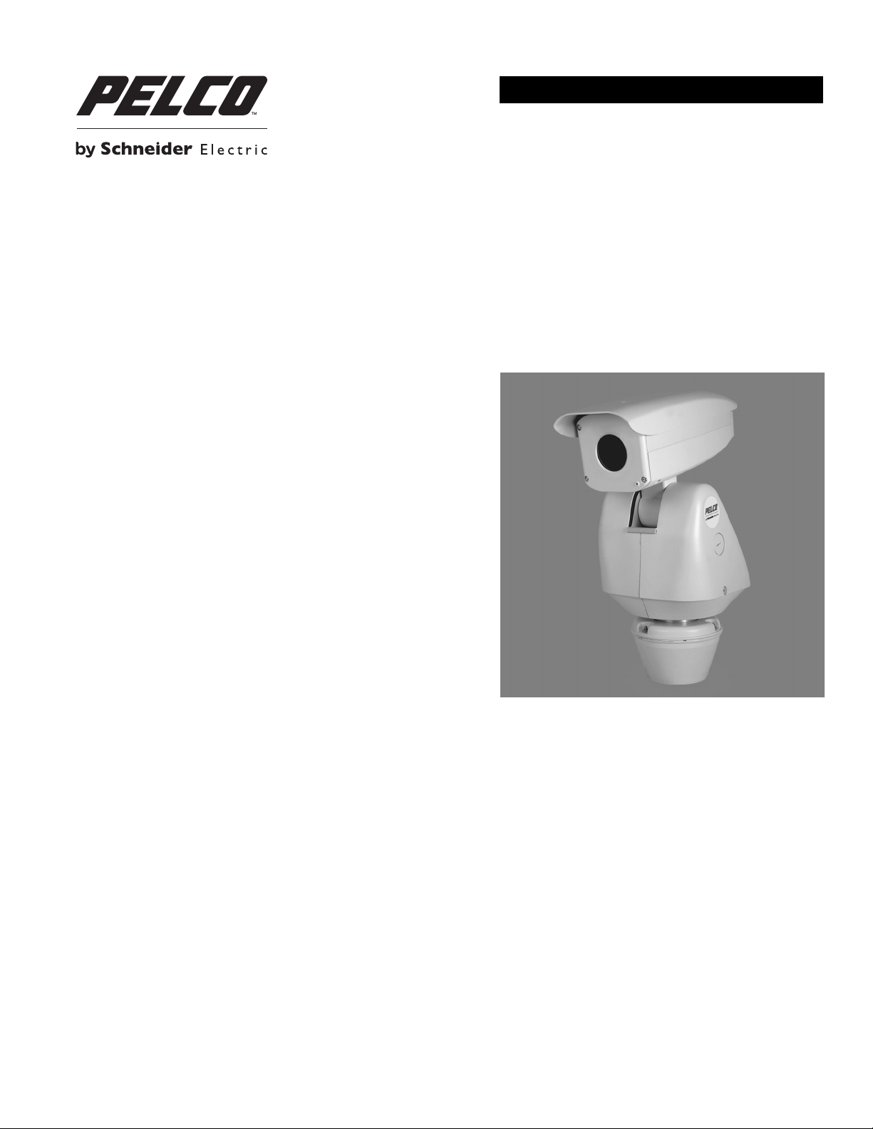
Sarix® TI Series Thermal IP Positioning System
C1317M-C (8/13)

Contents
List of Illustrations . . . . . . . . . . . . . . . . . . . . . . . . . . . . . . . . . . . . . . . . . . . . . . . . . . . . . . . . . . . . . . . . . . . . . . . . . . . . . . . . . . . . . . . . . . . . . . . . . . . . . 5
Important Notices . . . . . . . . . . . . . . . . . . . . . . . . . . . . . . . . . . . . . . . . . . . . . . . . . . . . . . . . . . . . . . . . . . . . . . . . . . . . . . . . . . . . . . . . . . . . . . . . . . . . . 6
Legal Notice . . . . . . . . . . . . . . . . . . . . . . . . . . . . . . . . . . . . . . . . . . . . . . . . . . . . . . . . . . . . . . . . . . . . . . . . . . . . . . . . . . . . . . . . . . . . . . . . . . . . . 6
Regulatory Notices . . . . . . . . . . . . . . . . . . . . . . . . . . . . . . . . . . . . . . . . . . . . . . . . . . . . . . . . . . . . . . . . . . . . . . . . . . . . . . . . . . . . . . . . . . . . . . . . 6
Video Quality Caution . . . . . . . . . . . . . . . . . . . . . . . . . . . . . . . . . . . . . . . . . . . . . . . . . . . . . . . . . . . . . . . . . . . . . . . . . . . . . . . . . . . . . . . . . . . . . . 6
Open Source Software Notice . . . . . . . . . . . . . . . . . . . . . . . . . . . . . . . . . . . . . . . . . . . . . . . . . . . . . . . . . . . . . . . . . . . . . . . . . . . . . . . . . . . . . . . 6
Introduction . . . . . . . . . . . . . . . . . . . . . . . . . . . . . . . . . . . . . . . . . . . . . . . . . . . . . . . . . . . . . . . . . . . . . . . . . . . . . . . . . . . . . . . . . . . . . . . . . . . . . . . . . . 7
Built-In Analytics. . . . . . . . . . . . . . . . . . . . . . . . . . . . . . . . . . . . . . . . . . . . . . . . . . . . . . . . . . . . . . . . . . . . . . . . . . . . . . . . . . . . . . . . . . . . . . . . . . 7
Compatible Systems . . . . . . . . . . . . . . . . . . . . . . . . . . . . . . . . . . . . . . . . . . . . . . . . . . . . . . . . . . . . . . . . . . . . . . . . . . . . . . . . . . . . . . . . . . . . . . . 7
Models . . . . . . . . . . . . . . . . . . . . . . . . . . . . . . . . . . . . . . . . . . . . . . . . . . . . . . . . . . . . . . . . . . . . . . . . . . . . . . . . . . . . . . . . . . . . . . . . . . . . . . . . . 8
Getting Started . . . . . . . . . . . . . . . . . . . . . . . . . . . . . . . . . . . . . . . . . . . . . . . . . . . . . . . . . . . . . . . . . . . . . . . . . . . . . . . . . . . . . . . . . . . . . . . . . . . 9
Parts List . . . . . . . . . . . . . . . . . . . . . . . . . . . . . . . . . . . . . . . . . . . . . . . . . . . . . . . . . . . . . . . . . . . . . . . . . . . . . . . . . . . . . . . . . . . . . . . . . . . . . . . . 9
User-Supplied Parts List . . . . . . . . . . . . . . . . . . . . . . . . . . . . . . . . . . . . . . . . . . . . . . . . . . . . . . . . . . . . . . . . . . . . . . . . . . . . . . . . . . . . . . . . . . . . 9
Product Overview. . . . . . . . . . . . . . . . . . . . . . . . . . . . . . . . . . . . . . . . . . . . . . . . . . . . . . . . . . . . . . . . . . . . . . . . . . . . . . . . . . . . . . . . . . . . . . . . . . . . . 10
Removing the Back Cover . . . . . . . . . . . . . . . . . . . . . . . . . . . . . . . . . . . . . . . . . . . . . . . . . . . . . . . . . . . . . . . . . . . . . . . . . . . . . . . . . . . . . . . . . . 11
Installation . . . . . . . . . . . . . . . . . . . . . . . . . . . . . . . . . . . . . . . . . . . . . . . . . . . . . . . . . . . . . . . . . . . . . . . . . . . . . . . . . . . . . . . . . . . . . . . . . . . . . . . . . . 12
Connecting a Relay Device . . . . . . . . . . . . . . . . . . . . . . . . . . . . . . . . . . . . . . . . . . . . . . . . . . . . . . . . . . . . . . . . . . . . . . . . . . . . . . . . . . . . . . . . . 16
Connecting Alarms . . . . . . . . . . . . . . . . . . . . . . . . . . . . . . . . . . . . . . . . . . . . . . . . . . . . . . . . . . . . . . . . . . . . . . . . . . . . . . . . . . . . . . . . . . . . . . . 17
Connecting Audio . . . . . . . . . . . . . . . . . . . . . . . . . . . . . . . . . . . . . . . . . . . . . . . . . . . . . . . . . . . . . . . . . . . . . . . . . . . . . . . . . . . . . . . . . . . . . . . . 19
Supervised Alarms. . . . . . . . . . . . . . . . . . . . . . . . . . . . . . . . . . . . . . . . . . . . . . . . . . . . . . . . . . . . . . . . . . . . . . . . . . . . . . . . . . . . . . . . . . . 17
Unsupervised Alarms. . . . . . . . . . . . . . . . . . . . . . . . . . . . . . . . . . . . . . . . . . . . . . . . . . . . . . . . . . . . . . . . . . . . . . . . . . . . . . . . . . . . . . . . . 18
Alarm Connections. . . . . . . . . . . . . . . . . . . . . . . . . . . . . . . . . . . . . . . . . . . . . . . . . . . . . . . . . . . . . . . . . . . . . . . . . . . . . . . . . . . . . . . . . . . 18
IP Operation . . . . . . . . . . . . . . . . . . . . . . . . . . . . . . . . . . . . . . . . . . . . . . . . . . . . . . . . . . . . . . . . . . . . . . . . . . . . . . . . . . . . . . . . . . . . . . . . . . . . . . . . . 20
Device Configuration Sequence . . . . . . . . . . . . . . . . . . . . . . . . . . . . . . . . . . . . . . . . . . . . . . . . . . . . . . . . . . . . . . . . . . . . . . . . . . . . . . . . . . . . . 20
Minimum System Requirements . . . . . . . . . . . . . . . . . . . . . . . . . . . . . . . . . . . . . . . . . . . . . . . . . . . . . . . . . . . . . . . . . . . . . . . . . . . . . . . . . . . . 20
Accessing the IP Camera . . . . . . . . . . . . . . . . . . . . . . . . . . . . . . . . . . . . . . . . . . . . . . . . . . . . . . . . . . . . . . . . . . . . . . . . . . . . . . . . . . . . . . . . . . 20
Logging On to the Camera . . . . . . . . . . . . . . . . . . . . . . . . . . . . . . . . . . . . . . . . . . . . . . . . . . . . . . . . . . . . . . . . . . . . . . . . . . . . . . . . . . . . . 20
Live Video Page. . . . . . . . . . . . . . . . . . . . . . . . . . . . . . . . . . . . . . . . . . . . . . . . . . . . . . . . . . . . . . . . . . . . . . . . . . . . . . . . . . . . . . . . . . . . . . . . . . 21
Live Video Page Icons . . . . . . . . . . . . . . . . . . . . . . . . . . . . . . . . . . . . . . . . . . . . . . . . . . . . . . . . . . . . . . . . . . . . . . . . . . . . . . . . . . . . . . . . 21
Pan/Tilt Controls . . . . . . . . . . . . . . . . . . . . . . . . . . . . . . . . . . . . . . . . . . . . . . . . . . . . . . . . . . . . . . . . . . . . . . . . . . . . . . . . . . . . . . . . . . . . 22
Selecting a Stream . . . . . . . . . . . . . . . . . . . . . . . . . . . . . . . . . . . . . . . . . . . . . . . . . . . . . . . . . . . . . . . . . . . . . . . . . . . . . . . . . . . . . . . . . . 22
Taking a Snapshot . . . . . . . . . . . . . . . . . . . . . . . . . . . . . . . . . . . . . . . . . . . . . . . . . . . . . . . . . . . . . . . . . . . . . . . . . . . . . . . . . . . . . . . . . . . 23
Settings Page . . . . . . . . . . . . . . . . . . . . . . . . . . . . . . . . . . . . . . . . . . . . . . . . . . . . . . . . . . . . . . . . . . . . . . . . . . . . . . . . . . . . . . . . . . . . . . . . . . . 23
Accessing the Camera Menus. . . . . . . . . . . . . . . . . . . . . . . . . . . . . . . . . . . . . . . . . . . . . . . . . . . . . . . . . . . . . . . . . . . . . . . . . . . . . . . . . . 23
System Tab . . . . . . . . . . . . . . . . . . . . . . . . . . . . . . . . . . . . . . . . . . . . . . . . . . . . . . . . . . . . . . . . . . . . . . . . . . . . . . . . . . . . . . . . . . . . . . . . . . . . . 24
Changing the Device Name . . . . . . . . . . . . . . . . . . . . . . . . . . . . . . . . . . . . . . . . . . . . . . . . . . . . . . . . . . . . . . . . . . . . . . . . . . . . . . . . . . . . 24
Configuring DHCP Time Server Settings . . . . . . . . . . . . . . . . . . . . . . . . . . . . . . . . . . . . . . . . . . . . . . . . . . . . . . . . . . . . . . . . . . . . . . . . . . 25
Configuring Manual Time Server Settings . . . . . . . . . . . . . . . . . . . . . . . . . . . . . . . . . . . . . . . . . . . . . . . . . . . . . . . . . . . . . . . . . . . . . . . . 25
Customizing the Appearance of the Text Overlay. . . . . . . . . . . . . . . . . . . . . . . . . . . . . . . . . . . . . . . . . . . . . . . . . . . . . . . . . . . . . . . . . . . 25
Generating a System Log. . . . . . . . . . . . . . . . . . . . . . . . . . . . . . . . . . . . . . . . . . . . . . . . . . . . . . . . . . . . . . . . . . . . . . . . . . . . . . . . . . . . . . 25
Rebooting the Camera . . . . . . . . . . . . . . . . . . . . . . . . . . . . . . . . . . . . . . . . . . . . . . . . . . . . . . . . . . . . . . . . . . . . . . . . . . . . . . . . . . . . . . . . 26
Restoring All Camera Defaults . . . . . . . . . . . . . . . . . . . . . . . . . . . . . . . . . . . . . . . . . . . . . . . . . . . . . . . . . . . . . . . . . . . . . . . . . . . . . . . . . 26
Downloading a Full Backup of Camera Settings . . . . . . . . . . . . . . . . . . . . . . . . . . . . . . . . . . . . . . . . . . . . . . . . . . . . . . . . . . . . . . . . . . . . 26
Uploading a Backup File to Restore Camera Settings. . . . . . . . . . . . . . . . . . . . . . . . . . . . . . . . . . . . . . . . . . . . . . . . . . . . . . . . . . . . . . . . 26
Network Tab . . . . . . . . . . . . . . . . . . . . . . . . . . . . . . . . . . . . . . . . . . . . . . . . . . . . . . . . . . . . . . . . . . . . . . . . . . . . . . . . . . . . . . . . . . . . . . . . . . . . 27
Changing the Hostname . . . . . . . . . . . . . . . . . . . . . . . . . . . . . . . . . . . . . . . . . . . . . . . . . . . . . . . . . . . . . . . . . . . . . . . . . . . . . . . . . . . . . . 27
Changing the HTTP Port. . . . . . . . . . . . . . . . . . . . . . . . . . . . . . . . . . . . . . . . . . . . . . . . . . . . . . . . . . . . . . . . . . . . . . . . . . . . . . . . . . . . . . . 28
Changing the HTTPS Port. . . . . . . . . . . . . . . . . . . . . . . . . . . . . . . . . . . . . . . . . . . . . . . . . . . . . . . . . . . . . . . . . . . . . . . . . . . . . . . . . . . . . . 28
Changing the RTSP Port. . . . . . . . . . . . . . . . . . . . . . . . . . . . . . . . . . . . . . . . . . . . . . . . . . . . . . . . . . . . . . . . . . . . . . . . . . . . . . . . . . . . . . . 28
Turning On DHCP . . . . . . . . . . . . . . . . . . . . . . . . . . . . . . . . . . . . . . . . . . . . . . . . . . . . . . . . . . . . . . . . . . . . . . . . . . . . . . . . . . . . . . . . . . . . 28
Configuring a Static IPv4 Address . . . . . . . . . . . . . . . . . . . . . . . . . . . . . . . . . . . . . . . . . . . . . . . . . . . . . . . . . . . . . . . . . . . . . . . . . . . . . . . 29
Selecting the Secure Sockets Layer Mode . . . . . . . . . . . . . . . . . . . . . . . . . . . . . . . . . . . . . . . . . . . . . . . . . . . . . . . . . . . . . . . . . . . . . . . . 30
Enabling Secure Shell . . . . . . . . . . . . . . . . . . . . . . . . . . . . . . . . . . . . . . . . . . . . . . . . . . . . . . . . . . . . . . . . . . . . . . . . . . . . . . . . . . . . . . . . 31
Configuring the 802.1x Port Security Settings . . . . . . . . . . . . . . . . . . . . . . . . . . . . . . . . . . . . . . . . . . . . . . . . . . . . . . . . . . . . . . . . . . . . . 31
2 C1317M-C (8/13)

Selecting SNMP Settings . . . . . . . . . . . . . . . . . . . . . . . . . . . . . . . . . . . . . . . . . . . . . . . . . . . . . . . . . . . . . . . . . . . . . . . . . . . . . . . . . . . . . 32
Configuring SNMP V2c . . . . . . . . . . . . . . . . . . . . . . . . . . . . . . . . . . . . . . . . . . . . . . . . . . . . . . . . . . . . . . . . . . . . . . . . . . . . . . . . . . . . . . . 32
Configuring SNMP V3 . . . . . . . . . . . . . . . . . . . . . . . . . . . . . . . . . . . . . . . . . . . . . . . . . . . . . . . . . . . . . . . . . . . . . . . . . . . . . . . . . . . . . . . . 32
Imaging Tab . . . . . . . . . . . . . . . . . . . . . . . . . . . . . . . . . . . . . . . . . . . . . . . . . . . . . . . . . . . . . . . . . . . . . . . . . . . . . . . . . . . . . . . . . . . . . . . . . . . . 33
Selecting the Color Palette . . . . . . . . . . . . . . . . . . . . . . . . . . . . . . . . . . . . . . . . . . . . . . . . . . . . . . . . . . . . . . . . . . . . . . . . . . . . . . . . . . . . 33
Changing the Sharpness . . . . . . . . . . . . . . . . . . . . . . . . . . . . . . . . . . . . . . . . . . . . . . . . . . . . . . . . . . . . . . . . . . . . . . . . . . . . . . . . . . . . . . 34
Changing the Image Enhancement . . . . . . . . . . . . . . . . . . . . . . . . . . . . . . . . . . . . . . . . . . . . . . . . . . . . . . . . . . . . . . . . . . . . . . . . . . . . . . 34
Configuring Noise Filtering . . . . . . . . . . . . . . . . . . . . . . . . . . . . . . . . . . . . . . . . . . . . . . . . . . . . . . . . . . . . . . . . . . . . . . . . . . . . . . . . . . . . 34
Configuring the Recalibration Settings . . . . . . . . . . . . . . . . . . . . . . . . . . . . . . . . . . . . . . . . . . . . . . . . . . . . . . . . . . . . . . . . . . . . . . . . . . . 34
Creating a Preset . . . . . . . . . . . . . . . . . . . . . . . . . . . . . . . . . . . . . . . . . . . . . . . . . . . . . . . . . . . . . . . . . . . . . . . . . . . . . . . . . . . . . . . . . . . . 34
Deleting a Preset . . . . . . . . . . . . . . . . . . . . . . . . . . . . . . . . . . . . . . . . . . . . . . . . . . . . . . . . . . . . . . . . . . . . . . . . . . . . . . . . . . . . . . . . . . . . 35
Creating a Preset Tour . . . . . . . . . . . . . . . . . . . . . . . . . . . . . . . . . . . . . . . . . . . . . . . . . . . . . . . . . . . . . . . . . . . . . . . . . . . . . . . . . . . . . . . . 35
Deleting a Preset from a Tour . . . . . . . . . . . . . . . . . . . . . . . . . . . . . . . . . . . . . . . . . . . . . . . . . . . . . . . . . . . . . . . . . . . . . . . . . . . . . . . . . . 35
Deleting a Preset Tour . . . . . . . . . . . . . . . . . . . . . . . . . . . . . . . . . . . . . . . . . . . . . . . . . . . . . . . . . . . . . . . . . . . . . . . . . . . . . . . . . . . . . . . . 35
Configuring the Speed Profile . . . . . . . . . . . . . . . . . . . . . . . . . . . . . . . . . . . . . . . . . . . . . . . . . . . . . . . . . . . . . . . . . . . . . . . . . . . . . . . . . . 36
Configuring the Pan Center Point . . . . . . . . . . . . . . . . . . . . . . . . . . . . . . . . . . . . . . . . . . . . . . . . . . . . . . . . . . . . . . . . . . . . . . . . . . . . . . . 36
Configuring the Pan Limit Stops . . . . . . . . . . . . . . . . . . . . . . . . . . . . . . . . . . . . . . . . . . . . . . . . . . . . . . . . . . . . . . . . . . . . . . . . . . . . . . . . 36
Configuring the Tilt Limit Stops. . . . . . . . . . . . . . . . . . . . . . . . . . . . . . . . . . . . . . . . . . . . . . . . . . . . . . . . . . . . . . . . . . . . . . . . . . . . . . . . . 36
A/V Streams Tab. . . . . . . . . . . . . . . . . . . . . . . . . . . . . . . . . . . . . . . . . . . . . . . . . . . . . . . . . . . . . . . . . . . . . . . . . . . . . . . . . . . . . . . . . . . . . . . . . 37
Selecting a Video Preset Configuration. . . . . . . . . . . . . . . . . . . . . . . . . . . . . . . . . . . . . . . . . . . . . . . . . . . . . . . . . . . . . . . . . . . . . . . . . . . 37
Configuring a Custom Video Stream Configuration . . . . . . . . . . . . . . . . . . . . . . . . . . . . . . . . . . . . . . . . . . . . . . . . . . . . . . . . . . . . . . . . . 37
Selecting the Audio Configuration Settings . . . . . . . . . . . . . . . . . . . . . . . . . . . . . . . . . . . . . . . . . . . . . . . . . . . . . . . . . . . . . . . . . . . . . . . 39
Users Tab . . . . . . . . . . . . . . . . . . . . . . . . . . . . . . . . . . . . . . . . . . . . . . . . . . . . . . . . . . . . . . . . . . . . . . . . . . . . . . . . . . . . . . . . . . . . . . . . . . . . . . 39
Selecting the Users and Groups Settings . . . . . . . . . . . . . . . . . . . . . . . . . . . . . . . . . . . . . . . . . . . . . . . . . . . . . . . . . . . . . . . . . . . . . . . . . 40
Enabling Remote Mode . . . . . . . . . . . . . . . . . . . . . . . . . . . . . . . . . . . . . . . . . . . . . . . . . . . . . . . . . . . . . . . . . . . . . . . . . . . . . . . . . . . . . . . 40
Creating a New User . . . . . . . . . . . . . . . . . . . . . . . . . . . . . . . . . . . . . . . . . . . . . . . . . . . . . . . . . . . . . . . . . . . . . . . . . . . . . . . . . . . . . . . . . 41
Editing a User. . . . . . . . . . . . . . . . . . . . . . . . . . . . . . . . . . . . . . . . . . . . . . . . . . . . . . . . . . . . . . . . . . . . . . . . . . . . . . . . . . . . . . . . . . . . . . . 41
Deleting a User . . . . . . . . . . . . . . . . . . . . . . . . . . . . . . . . . . . . . . . . . . . . . . . . . . . . . . . . . . . . . . . . . . . . . . . . . . . . . . . . . . . . . . . . . . . . . 41
Events Tab. . . . . . . . . . . . . . . . . . . . . . . . . . . . . . . . . . . . . . . . . . . . . . . . . . . . . . . . . . . . . . . . . . . . . . . . . . . . . . . . . . . . . . . . . . . . . . . . . . . . . . 42
Sources . . . . . . . . . . . . . . . . . . . . . . . . . . . . . . . . . . . . . . . . . . . . . . . . . . . . . . . . . . . . . . . . . . . . . . . . . . . . . . . . . . . . . . . . . . . . . . . . . . . 43
Handlers. . . . . . . . . . . . . . . . . . . . . . . . . . . . . . . . . . . . . . . . . . . . . . . . . . . . . . . . . . . . . . . . . . . . . . . . . . . . . . . . . . . . . . . . . . . . . . . . . . . 45
Analytic Configuration . . . . . . . . . . . . . . . . . . . . . . . . . . . . . . . . . . . . . . . . . . . . . . . . . . . . . . . . . . . . . . . . . . . . . . . . . . . . . . . . . . . . . . . . . . . . 49
Profiles . . . . . . . . . . . . . . . . . . . . . . . . . . . . . . . . . . . . . . . . . . . . . . . . . . . . . . . . . . . . . . . . . . . . . . . . . . . . . . . . . . . . . . . . . . . . . . . . . . . . 49
Calibrate Scene . . . . . . . . . . . . . . . . . . . . . . . . . . . . . . . . . . . . . . . . . . . . . . . . . . . . . . . . . . . . . . . . . . . . . . . . . . . . . . . . . . . . . . . . . . . . . 50
Behaviors . . . . . . . . . . . . . . . . . . . . . . . . . . . . . . . . . . . . . . . . . . . . . . . . . . . . . . . . . . . . . . . . . . . . . . . . . . . . . . . . . . . . . . . . . . . . . . . . . . 51
Zones . . . . . . . . . . . . . . . . . . . . . . . . . . . . . . . . . . . . . . . . . . . . . . . . . . . . . . . . . . . . . . . . . . . . . . . . . . . . . . . . . . . . . . . . . . . . . . . . . . . . . 52
Adaptive Motion . . . . . . . . . . . . . . . . . . . . . . . . . . . . . . . . . . . . . . . . . . . . . . . . . . . . . . . . . . . . . . . . . . . . . . . . . . . . . . . . . . . . . . . . . . . . 53
Camera Sabotage . . . . . . . . . . . . . . . . . . . . . . . . . . . . . . . . . . . . . . . . . . . . . . . . . . . . . . . . . . . . . . . . . . . . . . . . . . . . . . . . . . . . . . . . . . . 54
Loitering Detection . . . . . . . . . . . . . . . . . . . . . . . . . . . . . . . . . . . . . . . . . . . . . . . . . . . . . . . . . . . . . . . . . . . . . . . . . . . . . . . . . . . . . . . . . . 55
Object Counting . . . . . . . . . . . . . . . . . . . . . . . . . . . . . . . . . . . . . . . . . . . . . . . . . . . . . . . . . . . . . . . . . . . . . . . . . . . . . . . . . . . . . . . . . . . . . 56
Stopped Vehicle. . . . . . . . . . . . . . . . . . . . . . . . . . . . . . . . . . . . . . . . . . . . . . . . . . . . . . . . . . . . . . . . . . . . . . . . . . . . . . . . . . . . . . . . . . . . . 57
Analog Operation. . . . . . . . . . . . . . . . . . . . . . . . . . . . . . . . . . . . . . . . . . . . . . . . . . . . . . . . . . . . . . . . . . . . . . . . . . . . . . . . . . . . . . . . . . . . . . . . . . . . . 58
Operating Notes . . . . . . . . . . . . . . . . . . . . . . . . . . . . . . . . . . . . . . . . . . . . . . . . . . . . . . . . . . . . . . . . . . . . . . . . . . . . . . . . . . . . . . . . . . . . . . . . . 59
Environmental Range. . . . . . . . . . . . . . . . . . . . . . . . . . . . . . . . . . . . . . . . . . . . . . . . . . . . . . . . . . . . . . . . . . . . . . . . . . . . . . . . . . . . . . . . . 59
Pan/Tilt Functions . . . . . . . . . . . . . . . . . . . . . . . . . . . . . . . . . . . . . . . . . . . . . . . . . . . . . .
. . . . . . . . . . . . . . . . . . . . . . . . . . . . . . . . . . . . . 59
Turbo Mode . . . . . . . . . . . . . . . . . . . . . . . . . . . . . . . . . . . . . . . . . . . . . . . . . . . . . . . . . . . . . . . . . . . . . . . . . . . . . . . . . . . . . . . . . . . . . . . . 59
Preset Functions. . . . . . . . . . . . . . . . . . . . . . . . . . . . . . . . . . . . . . . . . . . . . . . . . . . . . . . . . . . . . . . . . . . . . . . . . . . . . . . . . . . . . . . . . . . . . 59
Zones . . . . . . . . . . . . . . . . . . . . . . . . . . . . . . . . . . . . . . . . . . . . . . . . . . . . . . . . . . . . . . . . . . . . . . . . . . . . . . . . . . . . . . . . . . . . . . . . . . . . . 59
Patterns . . . . . . . . . . . . . . . . . . . . . . . . . . . . . . . . . . . . . . . . . . . . . . . . . . . . . . . . . . . . . . . . . . . . . . . . . . . . . . . . . . . . . . . . . . . . . . . . . . . 59
Park . . . . . . . . . . . . . . . . . . . . . . . . . . . . . . . . . . . . . . . . . . . . . . . . . . . . . . . . . . . . . . . . . . . . . . . . . . . . . . . . . . . . . . . . . . . . . . . . . . . . . . 60
Accessing the Main Menu with Preset 95 . . . . . . . . . . . . . . . . . . . . . . . . . . . . . . . . . . . . . . . . . . . . . . . . . . . . . . . . . . . . . . . . . . . . . . . . 60
Configuration . . . . . . . . . . . . . . . . . . . . . . . . . . . . . . . . . . . . . . . . . . . . . . . . . . . . . . . . . . . . . . . . . . . . . . . . . . . . . . . . . . . . . . . . . . . . . . . . . . . 62
Az/El. . . . . . . . . . . . . . . . . . . . . . . . . . . . . . . . . . . . . . . . . . . . . . . . . . . . . . . . . . . . . . . . . . . . . . . . . . . . . . . . . . . . . . . . . . . . . . . . . . . . . . 62
Az/El Line . . . . . . . . . . . . . . . . . . . . . . . . . . . . . . . . . . . . . . . . . . . . . . . . . . . . . . . . . . . . . . . . . . . . . . . . . . . . . . . . . . . . . . . . . . . . . . . . . . 63
Azimuth Zero . . . . . . . . . . . . . . . . . . . . . . . . . . . . . . . . . . . . . . . . . . . . . . . . . . . . . . . . . . . . . . . . . . . . . . . . . . . . . . . . . . . . . . . . . . . . . . . 64
Camera Mode . . . . . . . . . . . . . . . . . . . . . . . . . . . . . . . . . . . . . . . . . . . . . . . . . . . . . . . . . . . . . . . . . . . . . . . . . . . . . . . . . . . . . . . . . . . . . . 64
Direction. . . . . . . . . . . . . . . . . . . . . . . . . . . . . . . . . . . . . . . . . . . . . . . . . . . . . . . . . . . . . . . . . . . . . . . . . . . . . . . . . . . . . . . . . . . . . . . . . . . 65
Direction Line. . . . . . . . . . . . . . . . . . . . . . . . . . . . . . . . . . . . . . . . . . . . . . . . . . . . . . . . . . . . . . . . . . . . . . . . . . . . . . . . . . . . . . . . . . . . . . . 65
Display Duration . . . . . . . . . . . . . . . . . . . . . . . . . . . . . . . . . . . . . . . . . . . . . . . . . . . . . . . . . . . . . . . . . . . . . . . . . . . . . . . . . . . . . . . . . . . . 66
Factory Reset . . . . . . . . . . . . . . . . . . . . . . . . . . . . . . . . . . . . . . . . . . . . . . . . . . . . . . . . . . . . . . . . . . . . . . . . . . . . . . . . . . . . . . . . . . . . . . . 67
Pan Limits. . . . . . . . . . . . . . . . . . . . . . . . . . . . . . . . . . . . . . . . . . . . . . . . . . . . . . . . . . . . . . . . . . . . . . . . . . . . . . . . . . . . . . . . . . . . . . . . . . 67
C1317M-C (8/13) 3

Park Time . . . . . . . . . . . . . . . . . . . . . . . . . . . . . . . . . . . . . . . . . . . . . . . . . . . . . . . . . . . . . . . . . . . . . . . . . . . . . . . . . . . . . . . . . . . . . . . . . . 69
Power Up Mode . . . . . . . . . . . . . . . . . . . . . . . . . . . . . . . . . . . . . . . . . . . . . . . . . . . . . . . . . . . . . . . . . . . . . . . . . . . . . . . . . . . . . . . . . . . . . 69
Speed Profile . . . . . . . . . . . . . . . . . . . . . . . . . . . . . . . . . . . . . . . . . . . . . . . . . . . . . . . . . . . . . . . . . . . . . . . . . . . . . . . . . . . . . . . . . . . . . . . 70
Tilt Limits . . . . . . . . . . . . . . . . . . . . . . . . . . . . . . . . . . . . . . . . . . . . . . . . . . . . . . . . . . . . . . . . . . . . . . . . . . . . . . . . . . . . . . . . . . . . . . . . . . 71
Zones . . . . . . . . . . . . . . . . . . . . . . . . . . . . . . . . . . . . . . . . . . . . . . . . . . . . . . . . . . . . . . . . . . . . . . . . . . . . . . . . . . . . . . . . . . . . . . . . . . . . . 72
Specifications . . . . . . . . . . . . . . . . . . . . . . . . . . . . . . . . . . . . . . . . . . . . . . . . . . . . . . . . . . . . . . . . . . . . . . . . . . . . . . . . . . . . . . . . . . . . . . . . . . . . . . . 73
Appendix . . . . . . . . . . . . . . . . . . . . . . . . . . . . . . . . . . . . . . . . . . . . . . . . . . . . . . . . . . . . . . . . . . . . . . . . . . . . . . . . . . . . . . . . . . . . . . . . . . . . . . . . . . . 77
4 C1317M-C (8/13)

List of Illustrations
1 Camera Features. . . . . . . . . . . . . . . . . . . . . . . . . . . . . . . . . . . . . . . . . . . . . . . . . . . . . . . . . . . . . . . . . . . . . . . . . . . . . . . . . . . . . . . . . . . . . . . . . 10
2 Removing the Back Cover . . . . . . . . . . . . . . . . . . . . . . . . . . . . . . . . . . . . . . . . . . . . . . . . . . . . . . . . . . . . . . . . . . . . . . . . . . . . . . . . . . . . . . . . . . 11
3 Removing the Power Module . . . . . . . . . . . . . . . . . . . . . . . . . . . . . . . . . . . . . . . . . . . . . . . . . . . . . . . . . . . . . . . . . . . . . . . . . . . . . . . . . . . . . . . 12
4 Attaching the Base . . . . . . . . . . . . . . . . . . . . . . . . . . . . . . . . . . . . . . . . . . . . . . . . . . . . . . . . . . . . . . . . . . . . . . . . . . . . . . . . . . . . . . . . . . . . . . . 13
5 Routing Wires and Cables . . . . . . . . . . . . . . . . . . . . . . . . . . . . . . . . . . . . . . . . . . . . . . . . . . . . . . . . . . . . . . . . . . . . . . . . . . . . . . . . . . . . . . . . . 13
6 Attaching Base and Pan/Tilt. . . . . . . . . . . . . . . . . . . . . . . . . . . . . . . . . . . . . . . . . . . . . . . . . . . . . . . . . . . . . . . . . . . . . . . . . . . . . . . . . . . . . . . . 15
7 Setting DIP Switches . . . . . . . . . . . . . . . . . . . . . . . . . . . . . . . . . . . . . . . . . . . . . . . . . . . . . . . . . . . . . . . . . . . . . . . . . . . . . . . . . . . . . . . . . . . . . 16
8 Wiring Diagram for Relay A . . . . . . . . . . . . . . . . . . . . . . . . . . . . . . . . . . . . . . . . . . . . . . . . . . . . . . . . . . . . . . . . . . . . . . . . . . . . . . . . . . . . . . . . 16
9 Wiring Diagram for Relay B . . . . . . . . . . . . . . . . . . . . . . . . . . . . . . . . . . . . . . . . . . . . . . . . . . . . . . . . . . . . . . . . . . . . . . . . . . . . . . . . . . . . . . . . 17
10 Supervised Alarm Conditions . . . . . . . . . . . . . . . . . . . . . . . . . . . . . . . . . . . . . . . . . . . . . . . . . . . . . . . . . . . . . . . . . . . . . . . . . . . . . . . . . . . . . . . 17
11 Supervised Alarm Input Wiring . . . . . . . . . . . . . . . . . . . . . . . . . . . . . . . . . . . . . . . . . . . . . . . . . . . . . . . . . . . . . . . . . . . . . . . . . . . . . . . . . . . . . 17
12 Unsupervised Alarm Conditions . . . . . . . . . . . . . . . . . . . . . . . . . . . . . . . . . . . . . . . . . . . . . . . . . . . . . . . . . . . . . . . . . . . . . . . . . . . . . . . . . . . . . 18
13 Normally Closed and Normally Open Unsupervised Alarm Input Wiring . . . . . . . . . . . . . . . . . . . . . . . . . . . . . . . . . . . . . . . . . . . . . . . . . . . . . 18
14 Alarm Connections . . . . . . . . . . . . . . . . . . . . . . . . . . . . . . . . . . . . . . . . . . . . . . . . . . . . . . . . . . . . . . . . . . . . . . . . . . . . . . . . . . . . . . . . . . . . . . . 18
15 Line-In Audio Wiring. . . . . . . . . . . . . . . . . . . . . . . . . . . . . . . . . . . . . . . . . . . . . . . . . . . . . . . . . . . . . . . . . . . . . . . . . . . . . . . . . . . . . . . . . . . . . . 19
16 Configuration Screen . . . . . . . . . . . . . . . . . . . . . . . . . . . . . . . . . . . . . . . . . . . . . . . . . . . . . . . . . . . . . . . . . . . . . . . . . . . . . . . . . . . . . . . . . . . . . 58
17 Analog Menu Tree . . . . . . . . . . . . . . . . . . . . . . . . . . . . . . . . . . . . . . . . . . . . . . . . . . . . . . . . . . . . . . . . . . . . . . . . . . . . . . . . . . . . . . . . . . . . . . . 62
18 Pedestal Mount Models . . . . . . . . . . . . . . . . . . . . . . . . . . . . . . . . . . . . . . . . . . . . . . . . . . . . . . . . . . . . . . . . . . . . . . . . . . . . . . . . . . . . . . . . . . . 75
19 Wall Mount Models . . . . . . . . . . . . . . . . . . . . . . . . . . . . . . . . . . . . . . . . . . . . . . . . . . . . . . . . . . . . . . . . . . . . . . . . . . . . . . . . . . . . . . . . . . . . . . 76
20 Pedestal Mounting Pattern . . . . . . . . . . . . . . . . . . . . . . . . . . . . . . . . . . . . . . . . . . . . . . . . . . . . . . . . . . . . . . . . . . . . . . . . . . . . . . . . . . . . . . . . . 76
21 Wall Mounting Pattern . . . . . . . . . . . . . . . . . . . . . . . . . . . . . . . . . . . . . . . . . . . . . . . . . . . . . . . . . . . . . . . . . . . . . . . . . . . . . . . . . . . . . . . . . . . . 76
C1317M-C (8/13) 5

Important Notices
LEGAL NOTICE
SOME PELCO EQUIPMENT CONTAINS, AND THE SOFTWARE ENABLES, AUDIO/VISUAL AND RECORDING CAPABILITIES, THE IMPROPER USE OF
WHICH MAY SUBJECT YOU TO CIVIL AND CRIMINAL PENALTIES. APPLICABLE LAWS REGARDING THE USE OF SUCH CAPABILITIES VARY
BETWEEN JURISDICTIONS AND MAY REQUIRE, AMONG OTHER THINGS, EXPRESS WRITTEN CONSENT FROM RECORDED SUBJECTS. YOU
ARE SOLELY RESPONSIBLE FOR INSURING STRICT COMPLIANCE WITH SUCH LAWS AND FOR STRICT ADHERENCE TO ANY/ALL RIGHTS OF
PRIVACY AND PERSONALTY. USE OF THIS EQUIPMENT AND/OR SOFTWARE FOR ILLEGAL SURVEILLANCE OR MONITORING SHALL BE DEEMED
UNAUTHORIZED USE IN VIOLATION OF THE END USER SOFTWARE AGREEMENT AND RESULT IN THE IMMEDIATE TERMINATION OF YOUR
LICENSE RIGHTS THEREUNDER.
REGULATORY NOTICES
This device complies with Part 15 of the FCC Rules. Operation is subject to the following two conditions: (1) this device may not cause harmful
interference, and (2) this device must accept any interference received, including interference that may cause undesired operation.
RADIO AND TELEVISION INTERFERENCE
This equipment has been tested and found to comply with the limits of a Class A digital device, pursuant to Part 15 of the FCC rules. These limits
are designed to provide reasonable protection against harmful interference when the equipment is operated in a commercial environment.
This equipment generates, uses, and can radiate radio frequency energy and, if not installed and used in accordance with the instruction manual,
may cause harmful interference to radio communications. Operation of this equipment in a residential area is likely to cause harmful interference
in which case the user will be required to correct the interference at his own expense.
Changes and Modifications not expressly approved by the manufacturer or registrant of this equipment can void your authority to operate this
equipment under Federal Communications Commission’s rules.
This Class A digital apparatus complies with Canadian ICES-003.
Cet appareil numérique de la classe A est conforme à la norme NMB-003 du Canada.
VIDEO QUALITY CAUTION
FRAME RATE NOTICE REGARDING USER-SELECTED OPTIONS
Pelco systems are capable of providing high quality video for both live viewing and playback. However, the systems can be used in lower quality
modes, which can degrade picture quality, to allow for a slower rate of data transfer and to reduce the amount of video data stored. The picture
quality can be degraded by either lowering the resolution, reducing the picture rate, or both. A picture degraded by having a reduced resolution
may result in an image that is less clear or even indiscernible. A picture degraded by reducing the picture rate has fewer frames per second,
which can result in images that appear to jump or move more quickly than normal during playback. Lower frame rates may result in a key event
not being recorded by the system.
Judgment as to the suitability of the products for users’ purposes is solely the users’ responsibility. Users shall determine the suitability of the
products for their own intended application, picture rate and picture quality. In the event users intend to use the video for evidentiary purposes in
a judicial proceeding or otherwise, users should consult with their attorney regarding any particular requirements for such use.
OPEN SOURCE SOFTWARE NOTICE
This product includes certain open source or other software originated from third parties that is subject to the GNU General Public License (GPL),
GNU Library/Lesser General Public License (LGPL) and different and/or additional copyright licenses, disclaimers, and notices.
The exact terms of GPL, LGPL, and some other licenses are provided to you with this product. Please refer to the exact terms of the GPL and LGPL
at http://www.fsf.org (Free Software Foundation) or http://www.opensource.org (Open Source Initiative) regarding your rights under said license.
You may obtain a complete corresponding machine-readable copy of the source code of such software under the GPL or LGPL by sending your
request to digitalsupport@pelco.com; the subject line should read Source Code Request. You will then receive an email with a link for you to
download the source code.
This offer is valid for a period of three (3) years from the date of the distribution of this product by Pelco.
6 C1317M-C (8/13)

Introduction
The Sarix® TI Series combines the power of an advanced thermal imaging device with the precision of an Esprit® positioning system. At the core
of the Sarix TI Series is an uncooled, sun-safe, amorphous silicon microbolometer, long wave infrared (LWIR) camera. Every Sarix TI Series
features IP and analog outputs in the same package. The pan/tilt positioner can be controlled using IP or analog systems that use Coaxitron® or
RS-422 Pelco D and Pelco P protocols.
The Sarix TI Series provides outstanding sensitivity below 50 mK. It is capable of multiple display formats, including white hot, black hot, and
rainbow. The Sarix TI Series is available with multiple lens configurations for effective deployment in a wide range of applications.
The camera features open architecture connectivity to third-party software. Pelco offers an application programming interface (API) and software
development kit (SDK) that enables third-party systems to interface with Pelco's IP cameras. The camera is also compatible with Endura
and Digital Sentry® to record, manage, configure, and view multiple live streams.
BUILT-IN ANALYTICS
When used in an IP video system, the Sarix TI Series is preloaded with user-configurable behaviors. The device is capable of running up to three
behaviors at the same time; however, the number of behaviors is limited to the available processing power of the camera and the type of analytic
being used.
Pelco analytics are configured and enabled using a standard Web browser. Refer to Analytic Configuration on page 47 for instructions on how to
configure and enable Pelco analytics.
COMPATIBLE SYSTEMS
The device can also be used with an Endura, DX Series, or Digital Sentry system. It also works with many third-party systems with Pelco’s API
and the ONVIF API. For detailed instructions on configuring the device using one of these systems, refer to the manual shipped with the system.
Go to partnerfirst.pelco.com for a list of compatible products and partners.
®
, DX,
C1317M-C (8/13) 7

MODELS
640 x 480 Resolution
Lens Format
35 mm
50 mm
100 mm
384 x 288 Resolution
Lens Format
14.25 mm
35 mm
50 mm
100 mm
Pedestal Mount Wall Mount
24 VAC 120/230 VAC 24 VAC 120/230 VAC
NTSC ESTI635-2N ESTI635-5N ESTI635-2W ESTI635-5W
PAL ESTI635-2N-X ESTI635-5N-X ESTI635-2W-X ESTI635-5W-X
PAL, 8.33 ips ESTI635-2N-X1 ESTI635-5N-X1 ESTI635-2W-X1 ESTI635-5W-X1
NTSC ESTI650-2N ESTI650-5N ESTI650-2W ESTI650-5W
PAL ESTI650-2N-X ESTI650-5N-X ESTI650-2W-X ESTI650-5W-X
PAL, 8.33 ips ESTI650-2N-X1 ESTI650-5N-X1 ESTI650-2W-X1 ESTI650-5W-X1
NTSC ESTI6100-2N ESTI6100-5N ESTI6100-2W ESTI6100-5W
PAL ESTI6100-2N-X ESTI6100-5N-X ESTI6100-2W-X ESTI6100-5W-X
PAL, 8.33 ips ESTI6100-2N-X1 ESTI6100-5N-X1 ESTI6100-2W-X1 ESTI6100-5W-X1
Pedestal Mount Wall Mount
24 VAC 120/230 VAC 24 VAC 120/230 VAC
NTSC ESTI314-2N ESTI314-5N ESTI314-2W ESTI314-5W
PAL ESTI314-2N-X ESTI314-5N-X ESTI314-2W-X ESTI314-5W-X
PAL, 8.33 ips ESTI314-2N-X1 ESTI314-5N-X1 ESTI314-2W-X1 ESTI314-5W-X1
NTSC ESTI335-2N ESTI335-5N ESTI335-2W ESTI335-5W
PAL ESTI335-2N-X ESTI335-5N-X ESTI335-2W-X ESTI335-5W-X
PAL, 8.33 ips ESTI335-2N-X1 ESTI335-5N-X1 ESTI335-2W-X1 ESTI335-5W-X1
NTSC ESTI350-2N ESTI350-5N ESTI350-2W ESTI350-5W
PAL ESTI350-2N-X ESTI350-5N-X ESTI350-2W-X ESTI350-5W-X
PAL, 8.33 ips ESTI350-2N-X1 ESTI350-5N-X1 ESTI350-2W-X1 ESTI350-5W-X1
NTSC ESTI3100-2N ESTI3100-5N EST3100-2W ESTI3100-5W
PAL ESTI3100-2N-X ESTI3100-5N-X ESTI3100-2W-X ESTI3100-5W-X
PAL, 8.33 ips ESTI3100-2N-X1 ESTI3100-5N-X1 ESTI3100-2W-X1 ESTI3100-5W-X1
8 C1317M-C (8/13)

GETTING STARTED
Before installing your camera, thoroughly familiarize yourself with the information in this section.
NOTES:
• While this camera can operate in both IP and analog modes, it is recommended that you use the camera in only one of these modes at any
given time, not both.
• Pelco recommends connecting the camera to a network that uses a Dynamic Host Configuration Protocol (DHCP) server to address devices.
• Do not use a network hub when configuring the network settings for the camera.
• To ensure secure access to the IP camera, place the camera behind a firewall when it is connected to a network.
PARTS LIST
The following parts are supplied:
Qty Description
1 Camera, pan/tilt, and power module
1 Quick Start Guide
1 Resource disc
3 MAC address labels (extra)
1 T20 security driver bit
USER-SUPPLIED PARTS LIST
Installation tools and mounting hardware are needed but not supplied.
C1317M-C (8/13) 9
Product Overview
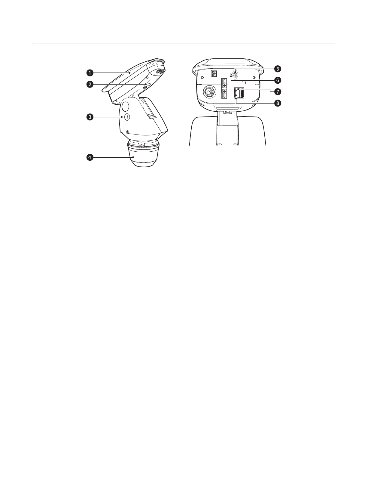
ì
Camera and Enclosure: Powder-coated aluminum IP66 rated enclosure with sun shroud protects the camera in both indoor and outdoor
environments.
î
Product Label: Lists the model number, date code, serial number, and Media Access Control (MAC) address. This information might be
required for setup.
ï
Pan/Tilt: Esprit pan/tilt positioner
Figure 1. Camera Features
ñ
Power Module: Provides power to the unit. If you are using a TXB Series translator board, it will be installed into the power module.
ó
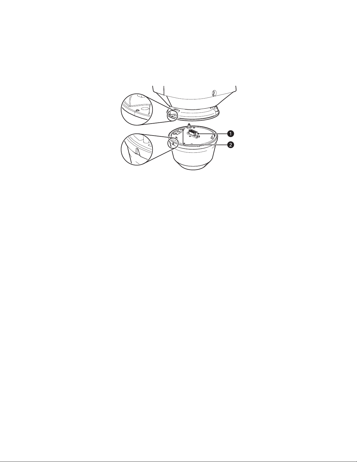
Micro SD Card Slot: Saves a snapshot image to a micro SD card based on alarm activity.
NOTE: The micro SD card must be formatted as FAT32. Other formats are not compatible with the camera.
r
Reset Button: Reboots the camera or restores the camera’s factory default settings. This button is recessed. Using a small tool, such as a
paper clip, press and release the reset button once to reboot the camera. Press and hold the reset button for 10 seconds to restore the
camera to the factory default settings.
s
Ethernet Link LED: Flashes green to indicate that a live network connection is established.
t
Ethernet Activity LED: Glows solid green to indicate that data is being transmitted or received by the camera.
NOTE: Figure 1 shows the camera with the back cover removed. The connectors on the back of the camera are not active. These connections
must be made using the color-coded wire harness attached to the pan/tilt. Refer to Installation on page 12 for more information.
10 C1317M-C (8/13)

REMOVING THE BACK COVER
To access the micro SD card slot, reset buttons, and Ethernet LEDs, you must first remove the back cover:
1. Loosen the two T20 security screws using a T20 security driver bit (supplied).
2. Remove the back cover.
Figure 2. Removing the Back Cover
C1317M-C (8/13) 11
Installation
1. When installing the device, allow for sufficient clearance between the top of the unit and overhead obstructions. This will prevent
interference when the enclosure is driven to its maximum tilt angles.Refer to the dimension drawings in Specifications on page 73
NOTE: Do not install the system behind a window or other glass. Glass is opaque to long wave infrared and will block the camera’s view.
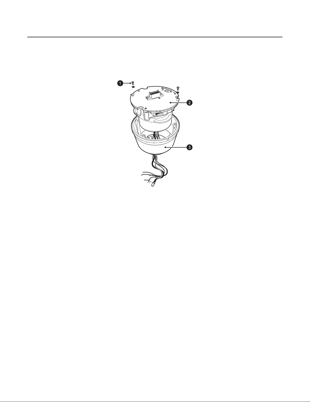
2. Remove the power module from the base of the system by loosening the two Phillips screws and lifting the module.
Figure 3. Removing the Power Module
ì
Phillips Screws
î
Power Module
ï
Base
12 C1317M-C (8/13)
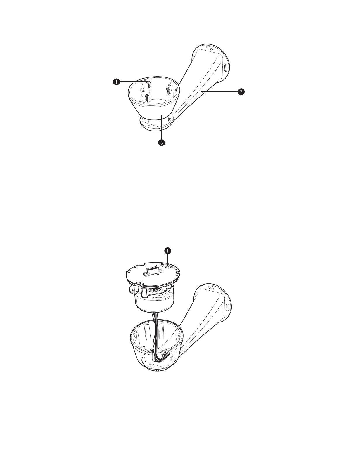
3. Attach the base of the system to a recommended mount with the three flathead 10-32 x 1/2-inch screws and washers (supplied).
Figure 4. Attaching the Base
ì
Flathead Mounting Screws
î
Mount
ï
Base
4. If you are installing an optional TXB Series translator board, you must do so before you reinstall the power module to the base. Refer to the
installation manual shipped with the translator board for more information.
5. Route the wires and cables through the center of the mount. Reinstall the power module into the base. The power module can be
positioned in the base in only one orientation.
Figure 5. Routing Wires and Cables
ì
120/230 Voltage Selector Switch
6. 120/230 VAC models only: Set the 120/230 voltage selector switch on the power module to the appropriate voltage.
C1317M-C (8/13) 13

7. Connect all wires and cables.
a. Connect the appropriate power wiring to AC power. Use the two supplied clamp connectors.
Tab l e A . Power Wire Colors
120/230 VAC 24 VAC
Black wire Input (AC Line) Black wire AC HI (HOT)
White wire AC Neutral Red wire AC LO (NEUT)
Green wire Ground
b. Connect the video cable.
• Analog installations: Connect the video coaxial cable to the BNC connector.
• IP installations: Connect the video Ethernet cable.
Table B. Ethernet Wire Colors
Orange/white wire TX+
Orange wire TX–
Green/white wire RX+
Green wire RX–
Brown wire N.C.
Brown/white wire N.C.
Blue wire N.C.
Blue/white wire N.C.
c. Connect the wiring for a 2-wire or 4-wire control system. This step does not apply to Coaxitron control systems.
Table C. Control Wire Colors
Green wire RX–
Green/white wire RX+
Brown wire TX–
Brown/white wire TX+
d. Optional: Connect the AUX 2 wiring. Refer to Connecting a Relay Device on page 16 and Connecting Alarms on page 17 for more
detailed information.
Table D. AUX 2 Wire Colors
Violet wire Alarm 1
Yellow wire Alarm 2
Orange wire Alarm 3
Blue wire Alarm COM
Brown wire Relay A1
Green wire Relay A2
Red wire COM
White wire N.O.
Black wire N.C.
e. Optional: Connect the audio wiring. Refer to Connecting Audio on page 19 for more detailed information.
Table E. Audio Wire Colors
Orange/white wire Mic Power +
Orange wire Mic Power –
Blue/white wire Audio In +
Blue wire Audio In –
14 C1317M-C (8/13)
8. Install the mount. Refer to the installation manual supplied with the mount for more information.
9. Turn on the system power. The red power LED is located on the top of the power module (refer to Figure 6 on page 15). If the red LED glows,
turn off the power and proceed to the next step.
NOTE: There might be a delay of approximately 3 minutes between power up and video being displayed in analog installations.
10. Align the triangle mark on the pan/tilt with the triangle mark on the base to ensure that the system connector on the pan/tilt and the base
are also aligned.
Figure 6. Attaching Base and Pan/Tilt
ì
System Connector
î
Power LED
11. Attach the pan/tilt to the base with three 1/4-20 nuts and washers (supplied).
12. Set the receiver address and system baud rate by configuring DIP switches SW1 and SW2.
NOTE: If you have a Coaxitron controller, refer to Appendix on page 77 for switch settings.
To set the DIP switches:
a. Remove the plug from the left cover of the pan/tilt. It is not necessary to remove the pan/tilt cover.
b. Set the baud rate (SW1) and receiver address (SW2). For switch settings, refer to Appendix on page 77.
c. Replace the plug.
C1317M-C (8/13) 15

13. Refer to IP Operation on page 20 and Analog Operation on page 58 for instructions on how to use your Sarix TI Series system.
NC
NO
COM
USER ACCESSORYSARIX TI
CONNECTING A RELAY DEVICE
NOTE: Relays must be configured using the Web interface.
The Sarix TI has two outputs for activating external devices. It supports both momentary and continuous relay operation.
ON
OFF
ON
OFF
Figure 7. Setting DIP Switches
SW2 SW1
1 2 3 4 5 6 7 8
1 2 3 4 5 6 7 8
DIP SWITCHES
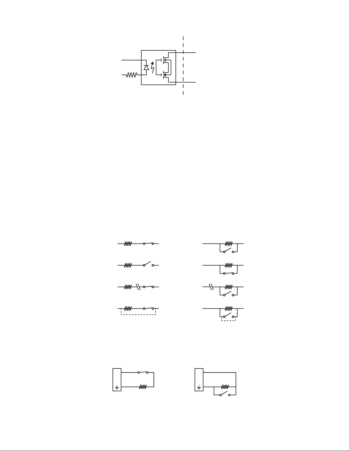
You can operate the relays interactively during an active connection, or they can operate automatically to coincide with certain events. Typical
applications include turning on lights or other electrical devices or activating a door, gate, or lock.
WARNING: Do not exceed the maximum relay ratings of 60 V, 600 mA for Relay A and 60 VDC, 125 VAC for Relay B.
Figure 8. Wiring Diagram for Relay A
16 C1317M-C (8/13)
CONNECTING ALARMS
1 KΩ
A
1
1 KΩ
A
1
NORMALLY OPENNORMALLY CLOSED
NOTE: Alarms must be configured using the Web interface.
The Sarix TI provides three alarm inputs for external signaling devices, such as door contacts or motion detectors. Both normally open and
normally closed devices are supported.
SUPERVISED ALARMS
When an alarm is configured as a supervised alarm, the Sarix TI maintains a constant electrical current through the alarm circuit
(3.3 VDC, 1 kohm). If the alarm circuit length changes, due to an electrical short or a bypass, the voltage fluctuates from its normal state and
activates an alarm.
NOTE: Install the 1-kohm resistor as close to the switch as possible.
USER ACCESSORYSARIX TI
A1
A2
Figure 9. Wiring Diagram for Relay B
Figure 10 illustrates the alarm and no alarm conditions of a supervised alarm input. Whether the alarm is normally closed or normally open,
neither a cut nor a bypass can defeat these alarms.
NORMALLY OPENNORMALLY CLOSED
NO ALARM
GND
ALARM
GND
ALARM
GND
ALARM
GND
1 KΩ
+V
1 KΩ
+V
1 KΩ
+V
CUT
1 KΩ
+V
BYPASS
NO ALARM
GND
ALARM
GND
ALARM
GND
ALARM
GND
1 KΩ
+V
1 KΩ
+V
1 KΩ
+V
CUT
1 KΩ
+V
BYPASS
Figure 10. Supervised Alarm Conditions
Figure 11 illustrates the wiring configuration for supervised alarm inputs.
Figure 11. Supervised Alarm Input Wiring
C1317M-C (8/13) 17
UNSUPERVISED ALARMS
+V
+V
+V
+V
+V
+V
+V
+V
BYPASS
CUT
BYPASS
CUT
GND
ALARM
GND
ALARM
GND
NO ALARM
GND
NO ALARM
GND
NO ALARM
GND
ALARM
GND
NO ALARM
GND
ALARM
NORMALLY OPENNORMALLY CLOSED
A1A1
NORMALLY OPENNORMALLY CLOSED
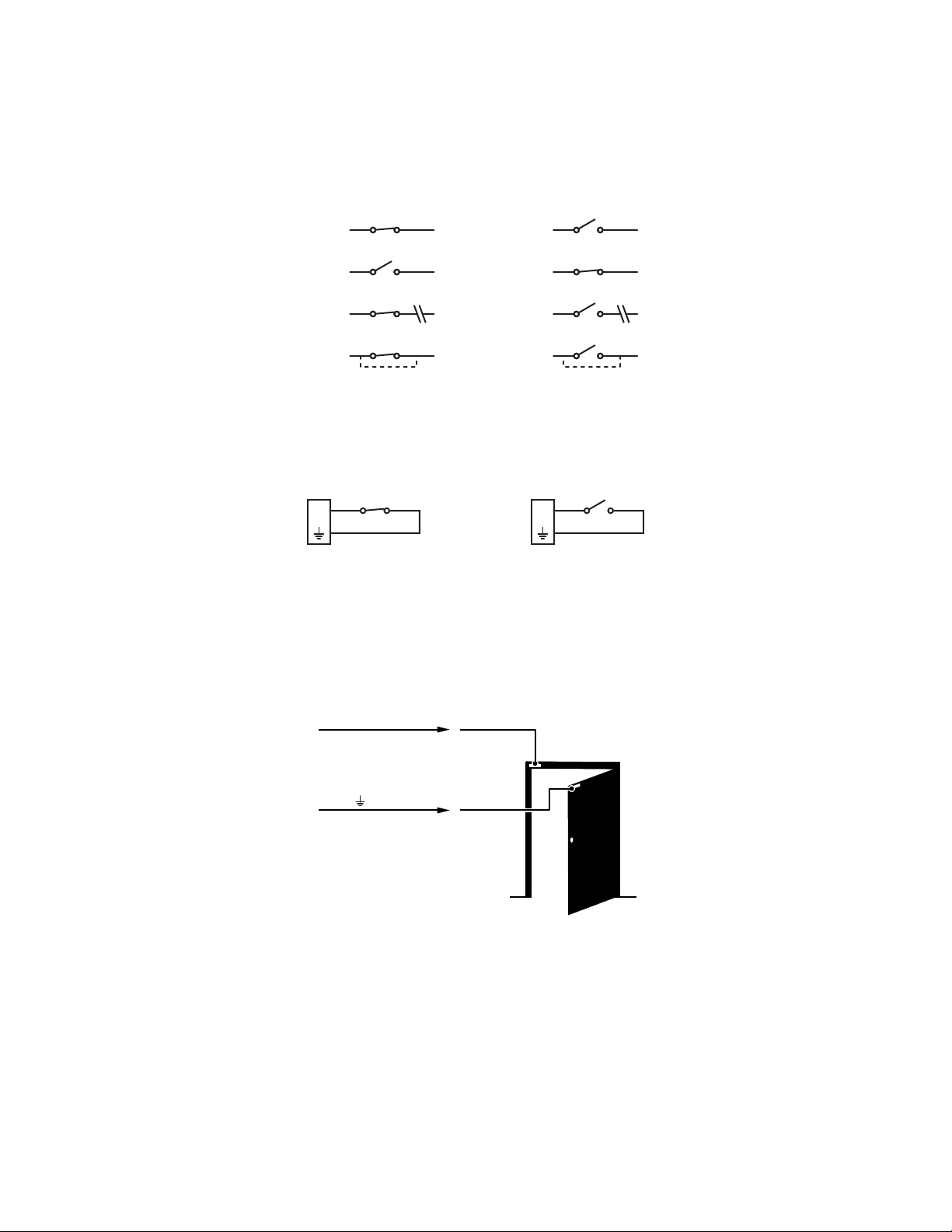
When an alarm is configured as an unsupervised alarm, an alarm is only activated when the normal alarm state (open or closed) changes.
Figure 12 illustrates the alarm and no alarm conditions of an unsupervised alarm input.
Figure 12. Unsupervised Alarm Conditions
Figure 13 illustrates the wiring configuration for unsupervised alarm inputs.
Figure 13. Normally Closed and Normally Open Unsupervised Alarm Input Wiring
NOTE: A normally closed alarm input can be defeated with a bypass; a normally open input can be defeated with a cut.
ALARM CONNECTIONS
Figure 14 shows how to wire the Sarix TI to an alarm.
ALARM A1
ALARM
Figure 14. Alarm Connections
18 C1317M-C (8/13)

CONNECTING AUDIO
NOTES:
• The maximum recommended cable length for the audio wiring is 304.8 m (1,000 ft).
• The Sarix TI is designed to work with microphones that have an internal preamplifier and provide professional line-level output (+4 dBu).
• If your microphone is a consumer line-level device (–10 dBu), the audio output may be quieter than you expect. Mic-level devices are not
recommended as they must be amplified to a line-level signal, which often results in excessive noise.
Figure 15. Line-In Audio Wiring
ì
Microphone
î
600-Ohm Impedance Matching Transformer
ï
UTP Wiring
ñ
0 V (zero volt) Return Wire
ó
+12 V Wire
C1317M-C (8/13) 19

IP Operation
DEVICE CONFIGURATION SEQUENCE
Once the device is installed and power is applied, the device undergoes a configuration sequence. The configuration sequence takes
approximately two minutes to complete, and then the device will come on line.
NOTE: If the device is not connected to a Dynamic Host Configuration Protocol (DHCP) server and DHCP is enabled, the configuration sequence
might take up to five minutes to complete.
MINIMUM SYSTEM REQUIREMENTS
Network interface card: 100 megabits (or greater)
Monitor: Minimum of 1024 x 768 resolution, 16- or 32-bit pixel color resolution
®
Web browser: Internet Explorer
analytics
Media player: Pelco Media Player or QuickTime
(or later)
NOTES:
• Pelco Media Player is recommended for control, smoothness, and reduced latency as compared to QuickTime.
• This product is not compatible with QuickTime version 7.6.4 for Windows XP or Windows Vista. If you have this version installed on your PC,
you will need to upgrade to QuickTime version 7.6.5.
• Network and processor bandwidth limitations might cause the video stream to pause or appear pixelated when additional Web-interface
users connect to the camera. Decrease the images per second (ips), resolution, compression, or bit rate settings of the Web interface video
streams to compensate for network or processor limitations.
8.0 (or later) or Mozilla® Firefox® 3.5 (or later); Internet Explorer 8.0 (or later) is recommended for configuring
®
7.6.5 for Windows XP, Windows Vista, and Windows 7; or QuickTime 7.6.4 for Mac OS X 10.4
ACCESSING THE IP CAMERA
The first time you access the camera, the live video page appears. By default, you are viewing the video as a public user and only have access to
the single stream live view.
If, for security purposes, users should not be allowed to view video without first logging on to the camera, change the permissions for public
users.
LOGGING ON TO THE CAMERA
1. Open the Web browser.
2. Type the camera’s IP address in the browser address bar.
NOTE: If you do not know the camera’s IP address, you can locate it using the Pelco Device Utility software.
3. Click the Login button in the navigation bar; a dialog box opens.
4. Type your user name and password.
NOTE: If you are logging on to the camera as the administrator for the first time, the default user name and password are admin
(all lowercase). For security purposes, be sure to change the password after you log on for the first time.
5. Click Log In.
20 C1317M-C (8/13)

LIVE VIDEO PAGE
The live video page allows you to manage the way you view live video and capture images. You can also view live video from this page and
access menus on the navigation bar (based on user permissions).
NOTE: The PTZ controls are viewable only after you have logged on to the device.
LIVE VIDEO PAGE ICONS
Viewable icons are based on user permissions.
Select Stream: Selects the viewable video stream that displays in live view (Primary, Secondary, QuickView, or Event) and selects
unicast or multicast and throttle settings.
Maximize Viewing Area: Scales the image to the full size of the browser. To resize the video pane to normal view, click the
Show Toolbar button in the upper-right corner of the window.
Show Toolbar: Returns the window to normal view. This icon is only available after the window has been set to maximize the
viewing area.
Open Stream in New Window: Opens the video in a scalable, independent window. Opening the video in a separate window allows
you to view the video while other applications are running. This window can be minimized, maximized, or closed using the title bar
buttons of the active window. The window can also be resized by dragging a corner of the window.
Take a Snapshot: Captures the image displayed in the video pane and saves it as a JPEG file.
Center Viewing Area*: Centers the camera on an area in the video pane. To center a viewing area, click the desired location in the
video pane.
Pan and Tilt*: Controls the pan and tilt functions. Click and drag the mouse to the left or right to pan the camera. Click and drag the
mouse up or down to tilt the camera.
Recalibrate Now: Immediately closes the shutter to improve video quality by removing noise from the image. During recalibration, the
video will freeze for approximately one-third of a second, and a small number of video frames will be lost.
Delay Recalibration: Delays closing the shutter by one minute.
C1317M-C (8/13) 21

PAN/TILT CONTROLS
NOTE: The PTZ controls are viewable only after you have logged on to the device.
Tilt Up: Click and hold the button to tilt the camera up.
Tilt Down: Click and hold the button to tilt the camera down.
Pan Left: Click and hold the button to pan the camera left.
Pan Right: Click and hold the button to pan the camera right.
Iris Open: Click and hold the button to open the iris and lighten the image.
Iris Close: Click and hold the button to close the iris and darken the image.
SELECTING A STREAM
1. Click the Select Stream button.
2. Select one of the following streams from the Select Stream page:
Primary Stream: To select this stream, click the button next to Primary Stream.
Secondary Stream: To select this stream, click the button next to Secondary Stream.
QuickView Stream: To select this stream, click the button next to QuickView Stream.
Event Stream: To select this stream, click the button next to Event Stream.
NOTE: If the secondary stream has not been configured, only Primary Stream, Event Stream, and QuickView Stream are available.
3. Configure the display settings for the selected stream. Available display settings are determined by the video compression of the selected
stream:
H.264 compression: For the Primary Stream or Secondary Stream. You can also select Unicast or Multicast from the Transmission dropdown menu.
JPEG compression: For the Secondary Stream or QuickView Stream, select Images Per Second (IPS) from the Throttle drop-down menu.
4. Click the Select button to save the stream settings.
Primary Stream and Secondary Stream
The Primary Stream and Secondary Stream are video streams that include compression, resolution, image rate, and bit rate settings. The streams
can be set up using a video configuration preset or they can be customized using the video configuration settings.
A video preset is a predefined video configuration that offers a good balance between video performance and bandwidth usage. For easy stream
configuration, use the Video Presets page located in the drop-down menu of the A/V Streams tab.
To customize the Primary Stream or Secondary Stream, select the Settings page and then use the Video Configuration page located in the dropdown menu of the A/V Streams tab. Configurable settings include the stream name, compression, resolution, image rate, bit rate, and I-frame
interval of the video streams. The default names for the streams are Primary Stream and Secondary Stream; however, if these stream names are
changed, the new names replace the default names (Primary Stream and Secondary Stream) on the Select Stream page.
QuickView Stream
The QuickView Stream is a predefined JPEG video stream with a lower resolution. This low resolution, low frame rate stream is available when
the Imaging tab settings are being configured. This allows users to view changes to exposure, white balance, and other settings as they are
configured and before the settings are saved.
22 C1317M-C (8/13)

The QuickView Stream is also ideal for users who are connected to a network with processor bandwidth limitations that might cause a high
resolution, high frame rate video stream to pause or appear pixilated.
The aspect ratio of the QuickView Stream mirrors that of the Primary Stream.
Event Stream
The Event Stream displays a list of alerts triggered by a running analytic behavior. The alert includes a screen capture, the profile that was
triggered, and the zone where the alert was detected. For the Event Stream to work you must have an analytic behavior profile running. To set up
and run analytic behaviors, profiles, and zones, use the Analytic Configuration page located in the drop-down menu of the Events tab.
Unicast
A unicast transmission sends a separate video stream to each user that is requesting data. Although multiple users might request the same data
from the camera at the same time, duplicate video streams are transmitted to each user. Every unicast user that connects to the camera
consumes additional processing power, which limits the number of simultaneous users who can access the camera.The camera supports a
maximum of 20 simultaneous users.
Multicast
A multicast transmission sends data to multiple users at the same time using one transmission stream. Each multicast user that connects to the
camera consumes no additional processing power; therefore, multicast video streams can be sent to an unlimited number of simultaneous users.
TAKING A SNAPSHOT
1. Click the Take a Snapshot button.
2. A dialog box opens, allowing you to open or save the file.
3. Select one of the following options:
Open: Your computer’s photo editing program opens and displays the screen image. This function is available only when using
Microsoft
Save: The image is saved as a JPEG file at the location you specify.
Cancel: The captured image is not opened or saved and the dialog box closes.
NOTE: If you are using JPEG, the captured image is the size of the largest MJPEG stream. If you are using MPEG-4 or H.264, the image is
captured using the QuickView Stream, which is a low resolution image.
SETTINGS PAGE
Depending on user permissions, the Settings page allows you to manage camera system and network settings, set up users, configure events,
and control the camera imaging and streams.
NOTE: The Settings menu might not be available if the user does not have permission to access this feature.
ACCESSING THE CAMERA MENUS
1. Log on to the camera.
2. Click the Settings link in the navigation bar located in the upper-right corner of the page; a list of menu tabs appears.
3. Place your mouse pointer over a tab to display a list of submenus.
®
Internet Explorer® 7.0 (or later) or Mozilla® Firefox® 3.0 (or later).
C1317M-C (8/13) 23

SYSTEM TAB
Use the System tab to change general system settings, configure the time settings, set up the text overlay for the live view, configure backup and
restore, display system information, and access snapshots generated by event handlers.
General System Settings
The general system settings page includes configurable fields for the device name, time settings, and text overlay settings. The device name is
the user-friendly description of the camera displayed in the gray area near the top of screen. The time server is an external server that uses
Network Time Protocol (NTP) to synchronize the camera date and time settings. The text overlay settings allow you to customize the appearance
of the video by displaying overlays such as the device name, or the date and time at the top or bottom of the video stream.
You can also use the general system settings page to turn the camera’s LEDs on or off and to configure the Simple Mail Transfer Protocol (SMTP)
server to send an email notification when an event handler is activated.
NOTE: Contact your network administrator for information on configuring email notification on your local network.
You can also use the general system settings page to generate a system log, reboot the camera, or restore the camera’s factory default settings.
Licensing Settings
The Licensing page provides an interface to add specialized features to your Sarix® device. Refer to license-specific documentation for more
information about installing licenses and the effects that a license might have on your device.
Backup and Restore Settings
The backup and restore settings page includes configurable fields for backup and restore of camera settings. Once the camera settings have
been configured for optimal scene display, use the backup feature to save the camera settings. If the camera settings are changed and
inadvertently result in a less desirable image, use the restore feature to restore the camera to the previously saved settings.
NOTE: This feature is not intended for the configuration of multiple units or for firmware upgrades.
Information Settings
The information settings page includes read-only fields for the firmware version, hardware version, model number, and serial number of the
camera. This information is typically required by Pelco Product Support for troubleshooting purposes.
Snapshot Viewer
The Snapshot Viewer page displays a list of snapshots saved to the SD card when a “Write JPEG to SD Card” event handler is activated. From
this page, you can open, download, or delete snapshots from the SD card. There are 100 snapshots displayed per page.
CHANGING THE DEVICE NAME
1. Place your mouse pointer over the System tab.
2. Select General Settings from the drop-down menu.
3. Click the Device Name box and highlight the text.
4. Type a user-friendly name into the Device Name box (2 to 63 characters). A user-friendly name makes it easier to recognize the device on
the network. Examples of user-friendly names are Front Door, Lobby, or Parking Lot.
5. Click Save to save the new device name, or click Reset to restore to the previously saved device name.
24 C1317M-C (8/13)

CONFIGURING DHCP TIME SERVER SETTINGS
The Auto setting allows the device to discover and synchronize with a network time server over IPv4 or IPv6. If a network time server is not
available for discovery on the network, select the Manual time server setting.
1. Place your mouse pointer over the System tab.
2. Select General Settings from the drop-down menu.
3. Select Auto for the Time Server.
4. Click the Save button to save the settings, or click the Reset button to clear all of the information you entered without saving it.
CONFIGURING MANUAL TIME SERVER SETTINGS
1. Place your mouse pointer over the System tab.
2. Select General Settings from the drop-down menu.
3. Select Manual for the Time Server.
4. Type the IP address or hostname of the time server in the Time Server box.
5. Configure the Time Zone by selecting the continent and region that are closest to the camera’s location from the Time Zone drop-down
menus.
NOTE: If your location observes a form of daylight saving time, the system automatically changes the time on the associated dates.
6. You can also specify time using an offset from Greenwich Mean Time (GMT) if you do not make a selection from the Time Zone drop-down
menu.
7. Click the Save button to save the settings, or click the Reset button to clear all of the information you entered without saving it.
CUSTOMIZING THE APPEARANCE OF THE TEXT OVERLAY
1. Place your mouse pointer over the System tab.
2. Select General Settings from the drop-down menu.
3. Set the Text Overlay settings:
Date/Time Overlay: Select Show to display the date and time in the live view overlay. The default setting is Hide.
Camera Name Overlay: Select Show to display the camera name in the live view overlay. The default setting is Hide.
Pan/Tilt Overlay: Select Show to display the pan, tilt, and direction position when moving the camera in the live view overlay. The default
setting is Hide.
4. Select the display position for the overlay from the Position drop-down menu. Selections include Top Right, Top Center, Top Left, Bottom
Right, Bottom Center, and Bottom Left.
5. If an overlay is set to Show, view the format of the overlay in the Overlay Format area.
6. Click the Save button to save the settings, or click the Reset button to clear all of the information you entered without saving it.
GENERATING A SYSTEM LOG
1. Place your mouse pointer over the System tab.
2. Select General Settings from the drop-down menu.
3. Click the Generate System Log button.
4. A dialog box opens, allowing you to open or save the file.
5. Save the file to create a system log that can be used by Pelco Product Support for troubleshooting. Contact Pelco Product Support at
1-800-289-9100 (USA and Canada) or +1-559-292-1981 (international).
C1317M-C (8/13) 25

REBOOTING THE CAMERA
1. Place your mouse pointer over the System tab.
2. Select General Settings from the drop-down menu.
3. Click the Reboot Camera button to restart the camera.
NOTE: Rebooting the camera does not change the configured camera settings.
RESTORING ALL CAMERA DEFAULTS
WARNING: This process cannot be undone; all user and custom settings will be lost.
1. Place your mouse pointer over the System tab.
2. Select General Settings from the drop-down menu.
3. Click the Restore All Camera Defaults button to restore the camera’s factory default settings.
NOTE: If the device is not connected to a Dynamic Host Configuration Protocol (DHCP) network, the IP address settings for the device will be lost
and the server will not recognize the device. The default setting for the device IP address is DHCP On.
DOWNLOADING A FULL BACKUP OF CAMERA SETTINGS
1. Place your mouse pointer over the System tab.
2. Select Backup and Restore from the drop-down menu.
3. Click the Download Now button. A file download dialog box opens.
4. Click Save and specify where you want to save the file.
5. Click OK to save the backup file, or click Cancel to stop the operation.
UPLOADING A BACKUP FILE TO RESTORE CAMERA SETTINGS
1. Place your mouse pointer over the System tab.
2. Select Backup and Restore from the drop-down menu.
3. Click the Browse button. A file upload dialog box opens.
4. Select the file you want to upload.
5. Click the Open button.
6. Click the Upload and Restore button.
NOTE: Restoring a backup file restarts the camera.
7. Click OK to restore the backup file, or click Cancel to stop the operation.
26 C1317M-C (8/13)

NETWORK TAB
Use the Network tab to change the camera’s general network settings, select the Secure Sockets Layer (SSL) settings, enable Secure Shell (SSH),
configure 802.1x port security, and select Simple Network Management Protocol (SNMP) settings.
General Network Settings
The general network settings page includes configurable and read-only fields for IPv4 and IPv6 network communication settings. The port
settings determine the ports over which the camera communicates using HTTP, HTTPS, and RTSP protocols. The hardware address is read-only.
IPv4 settings must be configured for the device. You can enable or disable the IPv4 DHCP setting from the general network settings page. If DHCP
is set to On, the IP address, subnet mask, gateway, and DNS server settings are automatically assigned to the device and are read-only text. If
DHCP is set to Off, these settings must be manually configured. The default camera setting for DHCP is On.
SSL Settings
The SSL settings page includes SSL configuration modes and certificate generation. To ensure security on the Internet, all Web browsers provide
several security levels that can be adjusted for sites that use SSL technology to transmit data. SSL encrypts communications, making it difficult
for unauthorized users to intercept and view user names and passwords.
SSL requires signed certificates to determine if the Web browser accessing the camera has the required authentication. The camera can
generate a certificate signing request (CSR) that can be sent to a certificate authority for a signature (for example, VeriSign
a self-signed certificate using the Generate Self-Signed Certificate option.
®
), or it can generate
SSH Settings
The SSH settings page enables or disables SSH access to the camera. SSH is a user-enabled protocol that allows Pelco Product Support to log on
to and service the camera for advanced troubleshooting purposes. From the SSH settings page, users with the appropriate permissions can
enable or disable SSH access to the camera.
802.1x Settings
The 802.1x settings page enables or disables 802.1x port security, which authenticates devices that want to establish a point-to-point access
through a wired or wireless port using Extensible Authentication Protocol (EAP) protocols. This port-based authentication method prevents
unauthorized access to a Local Area Network (LAN) through a physical port. For example, when a device is connected to a network port, the
network switch asks the device for authentication. The device replies with its credentials. If the credentials are accepted, the network switch
opens the port for normal use. If authentication fails, the device is prevented from accessing information on the port.
SNMP Settings
The SNMP setting page includes SNMP configuration settings. SNMP is an application layer protocol used to manage TCP/IP-based networks
from a single workstation or several workstations. The camera supports SNMP v2c and v3 and can be configured to send traps.
CHANGING THE HOSTNAME
1. Place your mouse pointer over the Network tab.
2. Select General from the drop-down menu.
3. View the read-only hardware address.
4. Click the Hostname box and highlight the text.
5. Type a user-friendly name into the Hostname box (1 to 21 characters) using alphanumeric characters. A user-friendly name makes it easier
to recognize the device on the network. Numeric-only names are not allowed.
6. Click the Save button to save the settings, or click the Reset button to clear all of the information you entered without saving it.
C1317M-C (8/13) 27

CHANGING THE HTTP PORT
NOTE: The HTTP port number must remain at the default setting of 80 when connecting to a Pelco video management system (VMS). If you are
connecting to a Pelco VMS, do not change the HTTP port setting.
1. Place your mouse pointer over the Network tab.
2. Select General from the drop-down menu.
3. Click the HTTP Port box and highlight the text.
4. Type a new port number for HTTP communications. The default setting is 80.
NOTE: Contact your network administrator before changing port settings to ensure they do not conflict with your network infrastructure.
5. Click the Save button to save the settings, or click the Reset button to clear all of the information you entered without saving it.
CHANGING THE HTTPS PORT
NOTE: Before configuring the HTTPS port, set the SSL configuration mode to either Optional or Required and install a security certificate.
1. Place your mouse pointer over the Network tab.
2. Select General from the drop-down menu.
3. Click the HTTPS Port box and highlight the text.
4. Type a new port number for HTTPS communications. The default setting is 443.
NOTE: Contact your network administrator before changing port settings to ensure they do not conflict with your network infrastructure.
5. Click the Save button to save the settings, or click the Reset button to clear all of the information you entered without saving it.
CHANGING THE RTSP PORT
NOTE: The camera uses the RTSP protocol to communicate with a video management system (VMS). Do not change the RTSP port unless you
are sure your VMS does not use the default RTSP port.
1. Place your mouse pointer over the Network tab.
2. Select General from the drop-down menu.
3. Click the RTSP Port box and highlight the text.
4. Type a new port number for RTSP communications. The default setting is 554.
NOTE: Contact your network administrator before changing port settings to ensure they do not conflict with your network infrastructure.
5. Click the Save button to save the settings, or click the Reset button to clear all of the information you entered without saving it.
TURNING ON DHCP
The default Dynamic Host Configuration Protocol (DHCP) setting for the camera is DHCP On. If DHCP is set to Off, complete the following steps to
reset it to On.
1. Place your mouse pointer over the Network tab.
2. Select General from the drop-down menu.
3. Select On for DHCP.
4. Click the Save button to save the settings, or click the Reset button to clear all of the information you entered without saving it.
NOTE: If the camera is not connected to a DHCP server but DHCP is set to On, the default IP address 192.168.0.20 on subnet mask 255.255.255.0
is automatically assigned to the camera. After the first camera is connected and assigned the default IP address, the system automatically looks
for other cameras on the auto IP address system and assigns IP addresses in sequential order as required. For example, if three cameras are
connected to a network without a DHCP server, the first camera is assigned address 192.168.0.20, the second camera is assigned address
192.168.0.21, and the third camera is assigned address 192.168.0.22.
28 C1317M-C (8/13)

CONFIGURING A STATIC IPV4 ADDRESS
WARNING: Contact your network administrator to avoid any network conflicts before setting or changing the IP address of the device.
1. Place your mouse pointer over the Network tab.
2. Select General from the drop-down menu.
3. Select Off for the Dynamic Host Configuration Protocol (DHCP).
4. Change the following network settings as required:
IP Address: The address of the camera connected to the network.
Subnet Mask: The address that determines the IP network to which the camera is connected (relative to its address).
Gateway: The router that accesses other networks.
DNS Servers: The addresses of the dedicated servers that translate the names for Web sites and host names into numeric IP addresses.
5. Click the Save button to save the settings, or click the Reset button to clear all of the information you entered without saving it.
CONFIGURING IPV6 ADDRESS SETTINGS
Your Sarix device supports IPv6 in conjunction with IPv4 configurations; the device does not support IPv6-only network deployments. The device
will accept up to sixteen IPv6 addresses, three IPv6 DNS servers, and three IPv6 gateways.
There are two configuration modes for IPv6 address assignments:
Auto: Enables automatic configuration using router advertisement. Additional configuration can be provided over DHCPv6 (if available on your
network). Selecting Auto mode still allows you to manually configure additional IPv6 addresses, DNS servers, and gateways.
Manual Only: Provides a link-local IPv6 address for the device and allows you to assign up to 16 static IPv6 addresses to the device.
1. Place your mouse pointer over the Network tab.
2. Select General from the drop-down menu.
3. Select On for IPv6.
4. Select a Configuration Mode from the drop-down box. Selecting Auto allows the device to configure the remaining IPv6 settings
automatically, rendering the remaining steps optional.
5. (Optional) Provide static, unicast addresses in the Manual IP Addresses box. Each address requires a prefix, and it must be input using the
format prefix/IPv6Address. Manual IP addresses without prefix information will be rejected.
6. (Optional) Provide the addresses of DNS servers that are not configured automatically in the Manual DNS Servers box.
7. (Optional) Provide the addresses of gateways that are not configured automatically in the Manual Gateways box.
NOTES:
• The device will not accept multicast, localhost, or undefined IPv6 addresses.
• Link-local addresses are not supported for DNS.
• Manually specified DNS servers supersede automatically discovered DNS servers.
• Manually specified DNS servers are not validated by the device; verify any manually specified DNS servers before saving IPv6 settings.
• Manually specified gateways must be on the same network as the devices’s IPv6 addresses. Behavior for a gateway that is not on the same
network as the device’s IPv6 addresses is undefined.
• Some video management systems (VMS), including Pelco VMS systems, do not support connections to cameras and encoders over IPv6.
C1317M-C (8/13) 29

SELECTING THE SECURE SOCKETS LAYER MODE
1. Place your mouse pointer over the Network tab.
2. Select SSL from the drop-down menu.
3. Select one of the following modes:
Disabled: Turns off access to the Web client through SSL. Sensitive data is not encrypted during transmission. The default setting is
disabled.
NOTE: If the SSL mode is set to disabled, you cannot access the camera using a URL that begins with an “https:” protocol. Your Web
browser displays an error message if you do not type the camera URL correctly.
Optional: A signed SSL certificate must be installed, but a secure URL that begins with the protocol name “https:” is optional when
accessing the camera. You can also access the camera using a standard URL with the “http:” protocol, but sensitive data is not encrypted
during transmission. To ensure that sensitive data is encrypted, you must use a secure URL with the “https:” protocol.
Required: A signed Secure Sockets Layer (SSL) certificate must be installed, and a secure URL that begins with the protocol name “https:”
must be used to access the camera. Sensitive data is always encrypted during transmission. A URL that begins with the “http:” protocol
rather than the “https:” protocol is redirected to the secure URL automatically.
NOTE: Beginning with firmware version 1.8.2, this mode cannot be modified in the Web browser. To select or clear the Required mode, you
must use the ONVIF or Pelco API call. Doing so avoids placing the camera into a mode in which it would no longer work with a connected
VMS system.
Generating a Certificate Request
1. Place your mouse pointer over the Network tab.
2. Select SSL from the drop-down menu.
3. Click the Install New Certificate button located at the bottom of the SSL Configuration page. The Select Certificate Install Method buttons
appear on the page.
4. Select Generate Certificate Request, and then click Next. The Generate Certificate Signing Request form opens.
5. Fill in all of the fields, and then click Generate Request. The following progress message appears on the page: “Generating certificate
signing request, please wait.”
6. Send the CSR, which looks like an encrypted block of undecipherable text, to a third-party certificate authority of your choice for a
signature. You will receive a signed certificate.
7. Click Choose File and browse to locate the certificate on your computer.
8. Click Open once you locate and select the certificate.
9. Click Upload Certificate to upload the signed certificate to the device.
10. After the certificate is uploaded, select the desired mode.
11. Click the Save button to save the settings, or click the Reset button to clear all of the information you entered without saving it.
NOTE: Depending on the third-party certificate authority that signed your certificate, you might need to renew your certificate after a specified
amount of time. Consult the certificate authority for more details.
30 C1317M-C (8/13)

Generating a Self-Signed Certificate
1. Place your mouse pointer over the Network tab.
2. Select SSL from the drop-down menu.
3. Click the Install New Certificate button located at the bottom of the SSL Configuration page. The Select Certificate Install Method buttons
appear on the page.
4. Select Generate Self-signed Certificate and then click Next. The Generate Self-signed Certificate form opens.
5. Fill in all of the fields, and then click the Generate Certificate button.
6. After the certificate is uploaded to the device, select the desired mode.
7. Click the Save button to save the settings, or click the Reset button to clear all of the information you entered without saving it.
NOTE: Self-signed certificates are valid for one year. The certificate’s expiration date is listed in the “Valid from” and To fields in the Certificate
section of the window. If the certificate has expired and you attempt to access the camera using a secure URL, the Web browser displays a
message. Repeat this procedure to generate and upload a new certificate.
ENABLING SECURE SHELL
1. Place your mouse pointer over the Network tab.
2. Select SSH from the drop-down menu.
3. Select the Enabled check box.
4. Click the Password box and type a password (4 to 16 alphanumeric characters). Passwords are case-sensitive.
NOTE: The default user name is “root” and cannot be changed. The user name and password are required when accessing the camera
through a third-party SSH client.
5. Click the Re-type Password box and retype your password.
6. Click the Save button to save the password and enable SSH, or click the Reset button to clear all of the information you entered without
saving it.
CONFIGURING THE 802.1X PORT SECURITY SETTINGS
WARNING: To prevent network conflicts, contact your network administrator before configuring the 802.1x port security settings.
1. Place your mouse pointer over the Network tab.
2. Select 802.1x from the drop-down menu.
3. Select On for the 802.1x port security. The default setting for 802.1x port security is Off.
4. Select the Extensible Authentication Protocol (EAP) method from the Protocol drop-down menu. Supported EAP methods include EAP-MD5,
EAP-TLS, EAP-TTLS, EAP-PEAP, and EAP-FAST.
5. Type the information required for the selected 802.1x EAP method.
6. Connect the PC to a 802.1x secured switch that has the same EAP method.
7. Click the Save button to save the settings, or click the Reset button to clear all of the information you entered without saving it.
C1317M-C (8/13) 31

SELECTING SNMP SETTINGS
WARNING: The Simple Network Management Protocol (SNMP) settings are advanced controls. Contact your network administrator to
obtain the required information to configure SNMP settings.
1. Place your mouse pointer over the Network tab.
2. Select SNMP from the drop-down menu.
3. Select the SNMP version to configure: SNMP V2c or SNMP V3. The default setting is No SNMP Server, which disables the SNMP
configuration.
NOTE: SNMP V2c and SNMP V3 configuration settings are independent of each other, but only one SNMP version can be active at a time.
CONFIGURING SNMP V2C
1. Place your mouse pointer over the Network tab.
2. Select SNMP from the drop-down menu.
3. Select SNMP V2c for the SNMP version.
4. Type the community name in the Community String box. The default name for the Community String is ”public.”
5. Configure the Trap Configuration settings:
Address: Type the host name or IP address of the trap server.
Community String: Type the community name for the trap server.
6. Click the Save button to save the settings, or click the Reset button to clear all of the information you entered without saving it.
CONFIGURING SNMP V3
1. Place your mouse pointer over the Network tab.
2. Select SNMP from the drop-down menu.
3. Select SNMP V3 for the SNMP version.
4. Type the SNMP user name in the SNMP user box.
5. Select the encryption algorithm for authentication from the Authentication drop-down menu. Support authentication settings include None,
MD5, or SHA. If you use authentication method MD5 or SHA, type a password in the box to the right of the selected Authentication
encryption.
6. Select the privacy encryption algorithm setting from the Privacy drop-down menu. Supported encryption settings include None, DES, or
AES. If you use privacy method DES or AES, type a password in the Privacy text box.
7. Type the host name or IP address of the trap server in the Address box under Trap Configuration.
8. Click the Save button to save the settings, or click the Reset button to clear all of the information you entered without saving it.
32 C1317M-C (8/13)

IMAGING TAB
Use the Imaging tab to change the camera’s general image settings, configure presets and preset tours, or configure positioning settings.
General Imaging Settings
General imaging settings include adjustments for the thermal color palette, sharpness, image enhancement, and recalibration.
The color palette programs the specific range of colors to represent the temperatures in the thermal image. These colors are not calibrated to a
specific temperature; rather, they represent the temperature variations within the thermal image.
The sharpness setting sharpens details in a scene. The image enhancement setting adjusts the thermal contrast range and detail of the image
definition of objects in the image; a higher image enhancement setting results in higher contrast and greater image detail with increased noise.
The noise filtering setting adjusts the strength of the automatic noise filter: lower noise filtering results in greater image detail with more noise,
and higher noise filtering results in lower noise and image detail. It is recommended that you configure the image enhancement setting before
the noise filtering setting.
Recalibration closes the shutter to improve video quality by removing noise from the image.
WARNINGS:
• When using the sharpness or image enhancement settings, be aware that picture noise, although unnoticeable to the eye, will
increase and may cause compression rate changes in DVRs, NVRs, and network devices.
• During recalibration, the video will freeze for approximately one-third of a second, and a small number of video frames will be lost.
Presets
A preset is a predetermined viewing area (such as a door) that a device will move to automatically when instructed, either by an operator
initiating a simple command or a software program executing an instruction. A maximum of 255 presets can be configured for the device. Presets
are available while viewing video.
Preset Tours
A preset tour is a grouping of presets that displays each predetermined viewing area in the sequence for a determined length of time before
displaying the next preset. A preset tour can contain a maximum of 64 presets in any order, and presets can be repeated anywhere in the
sequence.
Positioning
Positioning settings include the speed profile, pan center point, and pan and tilt limit stops.
The speed profile settings adjust the torque of the pan/tilt based on the wind speed conditions for the location of the Sarix TI system. High winds
may interfere with preset panning.
The pan and tilt limit stops control the pan and tilt range of the camera. When limit stops are set, a pan or tilt operation stops when a limit stop
is reached.
SELECTING THE COLOR PALETTE
1. Place your mouse pointer over the Imaging tab.
2. Select General from the drop-down menu.
3. Select one of the options from the Color Palette drop-down menu.
C1317M-C (8/13) 33

CHANGING THE SHARPNESS
1. Place your mouse pointer over the Imaging tab.
2. Select General from the drop-down menu.
3. Move the Sharpness slider to the right to increase the clarity of detail in a scene; move the slider to the left to decrease the clarity of detail
in a scene. The sharpness range is 0 (zero) to 100; the default setting is 50.
CHANGING THE IMAGE ENHANCEMENT
1. Place your mouse pointer over the Imaging tab.
2. Select General from the drop-down menu.
3. Move the Image Enhancement slider to the right to increase the contrast and detail in the scene; the noise in the scene increases. Move the
Image Enhancement slider to the left to decrease the contrast and detail in the scene; the noise in the scene dereases.
CONFIGURING NOISE FILTERING
NOTE: It is recommended that you configure image enhancement settings to produce the desired image contrast and detail before configuring
the noise filtering setting.
1. Place your pointer over the Imaging tab.
2. Select General from the drop-down menu.
3. Move the slider to the right to reduce noise in the image at the cost of image detail; move the slider to the left to maintain higher image
detail at the cost of increased video noise.
CONFIGURING THE RECALIBRATION SETTINGS
1. Place your mouse pointer over the Imaging tab.
2. Select General from the drop-down menu.
3. Select one of the following Recalibration settings:
Auto: Closes the camera shutter to automatically recalibrate as frequently as needed based on the camera conditions.
Periodic: Closes the camera shutter to recalibrate as often as specified.
Manual: Closes the camera shutter to recalibrate only when the user clicks the recalibrate buttons on the Live View page.
4. If you selected the periodic recalibration setting, click in the “Recalibrate every” box and type the frequency at which the camera should
recalibrate.
CREATING A PRESET
1. Place your mouse pointer over the Imaging tab.
2. Select Presets from the drop-down menu.
3. Click the New Preset button.
4. Type a name in the Preset Name box.
5. Position the camera using the pan and tilt controls.
6. Click the Save button to save the settings, or click the Reset button to clear all of the information you entered without saving it.
34 C1317M-C (8/13)

DELETING A PRESET
1. Place your mouse pointer over the Imaging tab.
2. Select Presets from the drop-down menu.
3. Select the preset that you want to delete from the Presets list.
4. Click the Delete Preset button.
CREATING A PRESET TOUR
1. Place your mouse pointer over the Imaging tab.
2. Select Preset Tours from the drop-down menu.
3. Click the New Tour button.
4. Type a name in the Tour Name box.
5. Select a preset from the list at the bottom of the page and drag it to the “Tour workspace” section of the window.
6. Set the dwell time for the preset. Dwell time can be set in minutes and seconds. Dwell time is the length of time (in minutes or seconds)
before the system moves to the next preset of the tour.
7. Move the Transition Speed slider to set the transition speed faster or slower.
8. Use the “Transition preview” pane to review the tour. Click the angle brackets icon (>>) to see additional presets. This icon is located
beneath the lower-right corner of the “Transition preview” pane.
9. Select another preset from the list and drag it to the right or left of an existing preset in the “Tour workspace” area. The border to either
side of the existing preset changes to yellow to indicate that you can add a preset at that location.
10. Continue adding presets to the tour. Be sure to add the dwell time and transition speed for each additional preset. Any preset can be added
to the tour; the same preset can be added several times.
11. If required, click the Refresh Selected Thumbnails button to refresh the selected preset thumbnails, or click Refresh All Thumbnails to
refresh all the preset thumbnails.
12. Click the Save button to save the settings, or click the Reset button to clear all of the information you entered without saving it.
DELETING A PRESET FROM A TOUR
1. Place your mouse pointer over the Imaging tab.
2. Select Preset Tours from the drop-down menu.
3. Select a tour in the Tours list.
4. In the “Tour workspace” area, locate the preset thumbnail you want to delete from the tour.
5. Click the Delete button ”X” next to the name of the preset.
6. Click the Save button to save the settings, or click the Reset button to clear all of the information you entered without saving it.
DELETING A PRESET TOUR
1. Place your mouse pointer over the Imaging tab.
2. Select Preset Tours from the drop-down menu.
3. Select a tour in the Tours list
4. Click the Delete Tour button.
C1317M-C (8/13) 35

CONFIGURING THE SPEED PROFILE
1. Place your mouse pointer over the Imaging tab.
2. Select Positioning from the drop-down menu.
3. Select 50 mph or 90 mph from the Profile drop-down menu.
4. Click the Save button to save the settings, or click the Reset button to clear all of the information you entered without saving it.
CONFIGURING THE PAN CENTER POINT
1. Place your mouse pointer over the Imaging tab.
2. Select Positioning from the drop-down menu.
3. Click the left and right arrow buttons next to the video preview pane on the right side of the window to pan the camera to the desired
location.
4. Select the Set New Pan Center Point button to set a new pan center point to the pan angle displayed in the video preview pane on the right
side of the window.
5. If required, click the Restore Default Center Point button to reset the pan center point to the 0 (zero) degree default.
CONFIGURING THE PAN LIMIT STOPS
1. Place your mouse pointer over the Imaging tab.
2. Select Positioning from the drop-down menu.
3. Select On for Pan Limit Stops. The default setting is Off.
4. Configure the left and right pan limits using one of the following methods:
• Type a value in degrees into the Left Pan Limit and Right Pan Limit boxes.
• Click the Get Current Pan button to configure the Left Pan Limit and Right Pan Limit boxes with the pan angle displayed in the video
preview pane on the right side of the window.
5. Click the Save button to save the settings, or click the Reset button to clear all of the information you entered without saving it.
CONFIGURING THE TILT LIMIT STOPS
1. Place your mouse pointer over the Imaging tab.
2. Select Positioning from the drop-down menu.
3. Select On for Tilt Limit Stops. The default setting is Off.
4. Configure the top and bottom tilt limits using one of the following methods:
• Type a value in degrees into the Top Tilt Limit and Bottom Tilt Limit boxes.
• Click the Get Current Tilt button to configure the Top Tilt Limit and Bottom Tilt Limit boxes with the tilt angle displayed in the video
preview pane on the right side of the window.
5. Click the Save button to save the settings, or click the Reset button to clear all of the information you entered without saving it.
36 C1317M-C (8/13)

A/V STREAMS TAB
Use the A/V Streams tab to configure the video and audio streams for the camera. The A/V Streams tab includes video presets settings, and
video and audio configuration.
Video Presets Settings
The video preset settings page includes three fully-configured video presets, High, Medium, and Low, which include primary and secondary video
stream settings for easy setup. These presets can also be used as a starting point for a custom video configuration.
vary depending on camera model.
Video Configuration Settings
The video configuration settings page allows you to customize the compression, resolution, image rate, bit rate, and I-frame interval of the video
streams. The default names for the streams are Primary Stream and Secondary Stream. Although each stream can be configured independently,
the settings of one stream can limit the options available to the other stream, depending on the processing power used.
NOTE: Always configure the primary stream before the secondary stream. The primary stream should always be the most resource-intensive of
the streams.
SELECTING A VIDEO PRESET CONFIGURATION
1. Place your mouse pointer over the A/V Streams tab.
2. Select Video Presets from the drop-down menu.
3. Click the button next to the desired video preset stream configuration.
These preset configurations
4. Click the Save button to save the settings, or click the Reset button to clear your selection without saving it.
CONFIGURING A CUSTOM VIDEO STREAM CONFIGURATION
1. Place your mouse pointer over the A/V Streams tab.
2. Select Video Configuration from the drop-down menu.
3. Click both of the Clear buttons to delete the primary and secondary streams settings.
4. Optional: In the Primary Stream section, type a user-friendly name in the Name box (2 to 64 characters). A user-friendly name makes it
easier to recognize the stream (for example, Live and Recording).
5. Configure the Compression Standard, Resolution, Image Rate, Bit Rate, and I-frame Interval settings for the primary stream.
NOTE: The compression standard, resolution, image rate, bit rate, and I-frame interval settings are dependent on each other. You must first
decide the priority setting before you configure a stream. For example, if you want an image rate of 30 ips, set the image rate before you
configure the other settings.
6. Configure QoS (DSCP) Codepoint, Endura Signing, Profile, and GOP Structure.
7. Repeat steps 3 to 5 for the Secondary stream.
8. Click the Save button to save the settings, or click the Reset button to clear all of the information you entered without saving it.
C1317M-C (8/13) 37

Compression Standards
JPEG: A commonly used video compression scheme. JPEG has the least impact on the camera’s processor, but it requires the most bandwidth.
MJPEG: Motion JPEG has the same characteristics as JPEG but differs in its mode of transfer (RTP).
H.264: Also known as MPEG-4 Part 10 or Advanced Video Coding (AVC), H.264 is one of the most widely used compression, recording, and
distribution methodologies for High Definition (HD) video. It is used in Blu-ray™ video players and by companies that transmit HD video or movies
over the internet and by satellite. H.264 is the most processor-intensive compression standard, but it requires the least amount of bandwidth.
Image Rate
The image rate is the number of images per second (ips) available for the video stream configuration. Available image rates depend upon the
model of the device that you are using.
NOTE: The maximum image rate setting might not be obtainable due to the compression standard and the resolution of the stream.
Bit Rate
The bit rate is the quality of the video stream (rendered in kilobits per second). The higher the value, the higher the video quality and bandwidth
required.
NOTE: When you change any of the video stream configuration settings, the camera automatically adjusts the bit rate. If you manually reduce
the bit rate lower than the camera's automatic setting, the image quality might be reduced and the stream selection options might be limited.
I-Frame Interval
The I-frame interval configures the number of partial frames that occur between full frames in the video stream. For example, in a scene where a
door opens and a person walks through, only the movements of the door and the person are stored by the video encoder. The stationary
background that occurs in the previous partial frames is not encoded, because no changes occurred in that part of the scene. The stationary
background is only encoded in the full frames. Partial frames improve video compression rates by reducing the size of the video. As the I-frame
interval increases, the number of partial frames increases between full frames. Higher values are recommended only on networks with high
reliability. This setting is available only with H.264.
Quality of Service for Differentiated Services Code Point
Quality of Service (QoS) for Differentiated Services Code Point (DSCP) is a code that allows the network to prioritize the transmission of different
types of data. This setting is available only with H.264.
NOTES:
• If you are not familiar with DSCP, contact your network administrator before changing this setting.
• Your network must be configured to use QoS. If you are unsure if your network is QoS-aware, contact your network administrator.
Endura Signing
Enabling the Endura Signing feature allows an Endura® system to authenticate video from an Endura recorded stream. This setting is available
only with H.264.
38 C1317M-C (8/13)

SELECTING THE AUDIO CONFIGURATION SETTINGS
To use audio with the camera if it does not have built-in audio support, you must connect an audio device to the accessory port. Once the device
is connected, audio can only be enabled through the primary stream.
Audio and video may not be synchronized when viewing and listening to the primary stream through a Web browser. You may experience a
three-second delay in video when viewing the primary stream with audio.
NOTE: Improper use of audio/visual recording equipment may subject you to civil and criminal penalties. Applicable laws regarding the use of
such capabilities vary between jurisdictions and may require, among other things, express written consent from the recorded subjects. You are
solely responsible for ensuring strict compliance with such laws and for strict adherence to any/all rights of privacy and personalty.
1. Place your mouse pointer over the A/V Streams tab.
2. Select Audio Configuration from the drop-down menu.
3. Select Enabled in the Audio section.
4. Select the audio device setting from the Audio Device drop-down box.
Native Line In: Enables audio from a microphone connected to the audio-in connector.
5. Select the sample rate from the Sample Rate drop-down box. The sample rate is the quality of the audio stream (rendered in hertz per
second). The higher the value, the higher the audio quality. Available sample rate settings are 8000 Hz and 12000 Hz. The default setting is
8000 Hz.
6. Select the encoding method for the audio device from the Encoding drop-down box. Available encoding methods are PCMU, PCMA, and
PCM16. The default setting is PCMU.
7. If required, click the button next to Mute to mute the audio device.
NOTE: Do not use the mute button on an audio device, as it will override the audio software settings. To mute the audio device, select
Mute located on the Audio Configuration page.
8. Set the sensitivity of the input level by moving the Input Level slider. Move the slider to the right to increase the sensitivity level; move it to
the left to decrease the sensitivity level. For example, if the camera is installed in a noisy environment or the connected microphone has a
built-in line amplifier, set the sensitivity to a low setting. The setting range is 0 to 100.
9. Click the Save button to save the settings, or click the Reset button to clear all of the information you entered without saving it.
USERS TAB
Use the Users tab to create and manage user accounts and to change the way the camera manages the users settings.
General Users Settings
The general users settings page sets the public user access level. This access level is a predefined set of user permissions that allows the
camera to be accessed without logging on. Available permissions depend on the model of the camera that you are using.
The general users settings page also allows you to change the way the camera manages users and groups. These settings can be managed on a
camera-to-camera basis (local mode) or by using a centralized server to apply changes to multiple cameras (remote mode).
Users Settings
The users settings page defines the access levels assigned to individuals logged on to the camera. Use this page to create, modify, or delete user
accounts for Administrators, Managers, Operators, and Viewers. User accounts are created to limit permissions.
C1317M-C (8/13) 39

SELECTING THE USERS AND GROUPS SETTINGS
1. Place your mouse pointer over the Users tab.
2. Select General Settings from the drop-down menu.
3. Select one of the following Authentication modes:
Open Authentication: Allows users to view video and use the camera API without validating user credentials. When Open Authentication
is selected, you can select “Require password for PTZ control” to limit PTZ control to authenticated users.
Closed Authentication: Requires users to possess valid credentials to view video and access the camera API. Before selecting Closed
Authentication, ensure that your video management system supports Closed Authentication mode.
4. Select one of the following User and Group Management modes to manage permissions of users and groups:
Local Mode: The camera manages users and groups locally. Any changes to users and groups affect only the camera that you are
accessing. The default setting is Local Mode.
Remote Mode: The camera authenticates and manages users through a Lightweight Directory Access Protocol (LDAP) server supported by
Microsoft
Selecting Remote Mode disables Local Mode and all management is done on the server.
5. Click the Save button to save the settings, or click the Reset button to clear all of the information you entered without saving it.
®
Active Directory®. This allows administrators to tie cameras and group permissions into existing single sign-on services (SSO).
WARNING: Remote Mode settings are advanced controls. Contact your network administrator to obtain the required information to
configure remote settings.
ENABLING REMOTE MODE
1. Place your mouse pointer over the Users tab.
2. Select General Settings from the drop-down menu.
3. Select Remote Mode. The default setting is Local Mode.
4. Type the IP address or host name of the LDAP server in the LDAP Server box.
5. Type the port over which the camera communicates with the LDAP server in the LDAP Port box. The default port for LDAP communications
is 389.
6. Type the distinguished name (DN) that is the basis for LDAP searches in the Base DN box.
7. Provide the template to format the user name (provided when the user logs on to the camera) for searches in the LDAP directory in the Bind
DN Template box.
8. Provide the LDAP search query for users found in the base DN in the Search Template box. The search must match an entry in the LDAP user
record to the bind name (user name).
9. Type the Group Mappings for each of the camera’s four user groups:
a. Type the common name (CN) and DN for the group of users to whom you want to grant admin access in the Admins box.
b. Type the CN and DN for the group of users to whom you want to grant manager access in the Managers box.
c. Type the CN and DN for the group of users to whom you want to grant operator access in the Operators box.
d. Type the CN and DN for the group of users to whom you want to grant viewer access in the Viewers box.
10. Type the credentials of a user who can be authenticated through the LDAP server in the User and Password boxes.
NOTE: Remote Mode (LDAP authentication) will not be enabled if you leave these boxes blank or do not provide valid credentials; this
ensures that you cannot lock yourself out of the camera with invalid or incorrect LDAP settings.
11. Click the Save button to save the settings, or click the Reset button to clear all of the information you entered without saving it.
40 C1317M-C (8/13)

CREATING A NEW USER
1. Place your mouse pointer over the Users tab.
2. Select Users from the drop-down menu.
3. Select the Access Level for the user:
Admins: Permissions include access to all camera settings.
Managers: Permissions include access to all settings except this user cannot modify user permissions or restore factory default settings.
Operators: Permissions include view video and pan and tilt functions.
Viewers: Permissions include view video and use the API.
4. Click the Username box and type a user name (2 to 32 alphanumeric characters). User names are not case-sensitive and are saved in
lowercase characters.
5. Click the Password box and type a password (4 to 64 alphanumeric characters). Passwords are case-sensitive.
6. Click the Retype Password box and retype your password.
7. Click the Save button to save the settings and create a new user (the new user profile appears in the Users box on the left side of the page),
or click the Reset button to clear all of the information you entered without saving it.
EDITING A USER
1. Place your mouse pointer over the Users tab.
2. Select Users from the drop-down menu.
3. Click the user profile that you want to edit from the Users box on the left side of the page.
4. If required, select a different Access Level for the user.
5. Double-click each of the password boxes to highlight the text. Type the new information in each password box.
NOTE: The Username cannot be modified; this box is read-only.
6. Click the Save button to save the settings, or click the Reset button to clear all of the information you entered without saving it.
DELETING A USER
1. Place your mouse pointer over the Users tab.
2. Select Users from the drop-down menu.
3. Click the user profile that you want to delete from the Users box located on the left side of the page.
4. Click the Delete User button. A dialog box opens and the following message appears “Are you sure you want to delete this user?”
5. Click OK. The user profile is deleted from the Users box.
NOTE: The “admin” user cannot be deleted.
C1317M-C (8/13) 41

EVENTS TAB
Use the Events tab to configure camera events and analytics.
Events are activated by user-defined event sources that tell the device how to react when an event occurs. Event handlers are the actions that
the device takes when an event occurs. For example, a system source can be configured to send email to an operator if the system shuts-down
and restarts.
Sources Settings
The sources settings page defines the camera functions that are automatically triggered by an event source. The camera supports Alarm,
Analytics, Park Action, System, and Timer sources. The Alarm source is the camera input for an external signaling device, such as a door contact
or motion detector. The Analytics source triggers when any configured behavior is detected. The Park Action source activates a user-defined
event if the camera is inactive for a specified period of time. The System source is activated when the camera restarts. The Timer source is a
user-defined event that activates an event after a specified amount of time.
Handlers Settings
The handlers settings page defines the actions that a camera takes when an event occurs. The camera supports Send Email, Upload JPEG to FTP
Server, Go to Preset, Open/Close Relay, and Run Tour handlers. The Send Email handler sends an email to a defined email address when an event
is activated. The Upload JPEG to FTP Server handler saves a JPEG of the activated event to a defined FTP server. The Go to Preset handler moves
the camera to a user-defined preset. The Open/Close Relay handler sends a signal to an external device when an alarm or relay is triggered. The
Run Tour handler starts a user-defined preset tour.
NOTE: The Pelco Alarm accessory must be connected to the camera’s accessory port for Open/Close Relay to work.
Analytic Configuration Settings
Pelco analytics can be configured and enabled using a standard Web browser. The device is preloaded with user-configurable behaviors and is
capable of running several behaviors at the same time. The number of behaviors is limited to the available processing power of the device.
Available processing power is determined by the settings for compression standards, resolution, image rate, bit rate, and analytic configuration.
®
Pelco analytics are also compatible with Endura
documentation for instructions on how to configure and enable Pelco analytics.
NOTE: Analytic alerts can be seen in the event stream, but alarms are only transmitted through Pelco’s API.
Models are also available with ObjectVideo® (OV) Suites. OV Suites require an OV ready-compliant system with an OV Ready™ video
management system to configure and enable the OV Analytic Suites that are preloaded on the camera. Refer to the ObjectVideo documentation
for instructions on how to configure and enable OV analytics.
Pelco analytics include the following behaviors:
Adaptive Motion: Detects and tracks objects that enter a scene and then triggers an alarm when the objects enter a user-defined zone. The
objects are monitored until they exit the scene.
Camera Sabotage: Detects contrast changes in the field of view. An alarm is triggered if the lens is obstructed with spray paint, a cloth, or
covered with a lens cap. Any unauthorized repositioning of the camera also triggers an alarm.
Loitering Detection: Identifies when people or vehicles remain in a defined zone longer than the user-defined time allows. This behavior is
effective for real-time notification of suspicious behavior around ATMs, stairwells, and school grounds.
Object Counting: Counts the number of objects that enter a defined zone or cross a defined trip wire. This behavior can be used to count people
at a store entrance/exit or inside a store where the traffic is light.
Stopped Vehicle: Detects vehicles stopped near a sensitive area longer than the user-defined time allows. This behavior is ideal for parking
enforcement, suspicious parking, traffic lane breakdowns, and vehicles waiting at gates.
or a third-party system that supports alarms using Pelco’s API. Refer to the specific product
42 C1317M-C (8/13)

SOURCES
An event is a preconfigured camera function that is activated automatically by an event source. The camera supports the following types of event
sources:
Alarm: If the Pelco Alarm accessory is connected to the device’s accessory port, the device can support alarm and auxiliary relay sources.
Analytics: An analytic source will activate a user-defined event handler when an analytic alert is detected.
System: A system source activates a user-defined event handler when the camera restarts.
Tim er: A timer source activates a user-defined event handler after a specified amount of time.
Creating an Alarm Event Source
1. Place your mouse pointer over the Events tab.
2. Select Sources from the drop-down menu.
3. In the New Event Source section of the window, click the Name box and type a user-friendly name (2 to 23 alphanumeric characters).
4. Select Alarm from the Type drop-down menu.
5. Select PCP from the Alarm Bank drop-down menu.
6. Select the alarm you want to trigger when an event occurs from the Alarm drop-down menu.
7. Move the Dwell Time slider to set the amount of time in seconds that the alarm is active. The dwell time range is 0.1 to 25 seconds;
the default setting is 0.1.
8. Select either Normally Open or Normally Closed from the Polarity drop-down menu.
9. Select either True or False from the Supervised drop-down menu.
10. Click the Submit button to save the settings, or click the Reset button to clear all of the information you entered without saving it.
Creating an Analytics Event Source
1. Place your mouse pointer over the Events tab.
2. Select Sources from the drop-down menu.
3. In the New Event Source section of the window, click the Name box and type a user-friendly name (2 to 23 alphanumeric characters).
4. Select Analytics from the Type drop-down menu.
5. Select the Any Analytics check box to activate an event when any analytic event occurs.
6. Click the Submit button to save the settings, or click the Reset button to clear all of the information you entered without saving it.
Creating a Park Action Event Source
1. Place your mouse pointer over the Events tab.
2. Select Sources from the drop-down menu.
3. In the New Event Source section of the window, click the Name box and type a user-friendly name (2 to 23 alphanumeric characters).
4. Select Park Action from the Type drop-down menu.
5. Configure the Dwell Time (the amount of inactivity before the event handler starts):
a. Click the Dwell Time box and type a number.
b. Select the time interval from the drop-down menu. Time intervals include seconds, minutes, hours, or days. The default setting is
seconds.
6. Click the Submit button to save the settings, or click the Reset button to clear all of the information you entered without saving it.
C1317M-C (8/13) 43

Creating a System Event Source
1. Place your mouse pointer over the Events tab.
2. Select Sources from the drop-down menu.
3. In the New Event Source section of the window, click the Name box and type a user-friendly name (2 to 23 alphanumeric characters).
4. Select System from the Type drop-down menu.
5. Select the Boot check box to activate an event when the camera reboots.
6. Click the Submit button to save the settings, or click the Reset button to clear all of the information you entered without saving it.
Creating a Timer Event Source
1. Place your mouse pointer over the Events tab.
2. Select Sources from the drop-down menu.
3. In the New Event Source section of the window, click the Name box and type a user-friendly name (2 to 23 alphanumeric characters).
4. Select Timer from the Type drop-down menu.
5. Configure the frequency:
a. Select the time interval from the drop-down menu. Time intervals include seconds, minutes, hours, or days. The default setting is
seconds.
b. Click the Frequency box and type a number.
6. Click the Submit button to save the settings, or click the Reset button to clear all of the information you entered without saving it.
Editing an Event Source
1. Place your mouse pointer over the Events tab.
2. Select Sources from the drop-down menu.
3. Click the source profile that you want to edit from the Sources box located on the left side of the page.
4. Make your changes to the available fields in the Edit Event Source section of the window.
5. Click the Submit button to save the settings, or click the Reset button to clear all of the information you entered without saving it.
Deleting an Event Source
1. Place your mouse pointer over the Events tab.
2. Select Sources from the drop-down menu.
3. Click the source profile that you want to delete from the Sources box located on the left side of the page.
4. Click the Delete Source button. The source profile is deleted from the Sources box.
44 C1317M-C (8/13)

HANDLERS
Event handlers are the actions that the camera takes when an event occurs. The camera supports the following event handlers:
Send Email: Sends an email to a defined email address when an event is activated. The Simple Mail Transfer Protocol (SMTP) server must be
configured to accept the camera’s IP address.
Write JPEG to SD Card: Saves a JPEG of the activated event to an SD card. An SD card must be installed in the device for this handler to
function.
NOTE: The SD card must be formatted as FAT32. Other formats are not compatible with the camera.
Upload JPEG to FTP Server: Saves a JPEG of the activated event to a defined FTP server.
Open/Close Relay: Sends a signal to an external device when an alarm or relay is triggered.
Go to Preset: Moves a device to a selected preset position.
Run Tour: Starts a selected preset tour.
Creating an Event Handler: Send Email
NOTE: To use email notification, the camera must be connected to a local area network (LAN) that maintains an SMTP mail server. Contact your
network administrator for information on configuring email notification on your local network.
1. Configure the SMTP server to send email.
2. Place your mouse pointer over the Events tab.
3. Select Handlers from the drop-down menu.
4. In the New Event Handler section of the window, click the Name box and type a user-friendly name (2 to 23 alphanumeric characters).
5. Select Send Email from the Type drop-down menu.
6. Click the boxes (To, From, Subject, and Message), and then type the necessary information in each box.
7. Select the JPEG Snapshot box if you want to send a JPEG as an attachment.
8. Select the Attach Raw Event Data box if you want the email to include extra data about the event. For example, select this box if the event
is triggered by an alarm and you want to receive data about the state, time, or type of alarm.
9. If you do not want the handler to activate every time an event occurs, set filters for the handler:
a. Select the day(s) of the week on which you want emails to be sent.
b. Type times in the Start and End boxes for the days you have selected. Use time values in 24-hour notation (for example, use 0800 for
8:00 a.m., 1600 for 4:00 p.m.).
c. If required, click the plus button (+) to add another time range.
10. Select one or more event sources to send an email when those event sources are activated.
11. Click the Submit button to save the settings, or click the Reset button to clear all of the information you entered without saving it.
C1317M-C (8/13) 45

Creating an Event Handler: Write JPEG to SD Card
1. Install an SD card in the SD card slot located on the back of the camera.
NOTE: The SD card must be formatted as FAT32. Other formats are not compatible with the camera.
2. Place your mouse pointer over the Events tab.
3. Select Handlers from the drop-down menu.
4. Click in the Name box and type a user-friendly name (2 to 23 alphanumeric characters).
5. Select the Write JPEG to SD Card option from the Type drop-down menu.
6. The JPEG files saved to the SD card will be given file names that correspond to the date and time of the event. Select a time standard from
the File Name drop-down menu.
7. Click in the Size limit box and type a number. Select Kilobytes, Megabytes, or Gigabytes from the Size Limit drop-down menu.
NOTE: Do not select a size limit that is larger than the amount of memory on the SD card. For example, if the SD card is 2 MB, do not
exceed 2 MB in the Size Limit box.
8. If you do not want the handler to activate every time an event occurs, set filters for the handler.
a. Select the day(s) of the week on which you want JPEGs saved to the SD card.
b. Type times in the Start and End boxes for the days you have selected. Use time values in 24-hour notation (for example, use 0800 for
8:00 a.m., 1600 for 4:00 p.m.).
9. Select one or more sources to save a JPEG to the SD card when those event sources are activated.
10. Click the Submit button to save the settings, or click the Reset button to clear all of the information you entered without saving it.
Creating an Event Handler: Upload JPEG to FTP Server
1. Place your mouse pointer over the Events tab.
2. Select Handlers from the drop-down menu.
3. In the New Event Handler section of the window, click the Name box and type a user-friendly name (2 to 23 alphanumeric characters).
4. Select the Upload JPEG to FTP Server option from the Type drop-down menu.
5. Click the Server box and type the server address (1 to 32 alphanumeric characters).
6. Click the Username box and type the user’s name (1 to 32 alphanumeric characters).
7. Click the Password box and type a password (4 to 16 alphanumeric characters).
8. Click the Base Path box and type the base path (1 to 32 alphanumeric characters). The base path is the path to your root directory.
9. Select a time standard from the File Name drop-down menu. The JPEG files uploaded to the FTP server are given file names that
correspond to the date and time of the event.
10. If you do not want the handler to activate every time an event occurs, set filters for the handler:
a. Select the day(s) of the week on which you want JPEGs saved to the FTP server.
b. Type times in the Start and End boxes for the days you have selected. Use time values in 24-hour notation (for example, use 0800 for
8:00 a.m., 1600 for 4:00 p.m.).
c. If required, click the plus button (+) to add another time range.
11. Select one or more sources to save a JPEG to the FTP server when those event sources are activated.
12. Click the Submit button to save the settings, or click the Reset button to clear all of the information you entered without saving it.
46 C1317M-C (8/13)

Creating an Event Handler: Open/Close Relay
1. Place your mouse pointer over the Events tab.
2. Select Handlers from the drop-down menu.
3. In the New Event Handler section of the window, click the Name box and type a user-friendly name (2 to 23 alphanumeric characters).
4. Select Open/Close Relay in the Type drop-down menu.
5. Select the serial number of the relay device from the Relay Bank drop-down menu.
6. Select either PCP or the serial number of the relay device from the Relay Bank drop-down menu.
7. Select the relay you want to trigger when an event occurs from the Relay drop-down menu.
8. Move the On Time slider to set the amount of time for the relay to remain open. The time range is 0.1 to 200 seconds; the default setting
is 0.1.
9. Move the Off Time slider to set the amount of time for the relay to remain closed. The time range is 0.1 to 200 seconds; the default setting
is 0.1.
10. Click the Pulse Count box and type a number. The pulse count is the number of relay pulses (number of on and off cycles).
11. If you do not want the handler to activate every time an event occurs, set filters for the handler:
a. Select the day(s) of the week on which you want the relay opened or closed.
b. Type times in the Start and End boxes for the days you have selected. Use time values in 24-hour notation (for example, use 0800 for
8:00 a.m., 1600 for 4:00 p.m.).
12. Select one or more event sources to open/close the relay when those event sources are activated.
13. Click the Submit button to save the settings, or click the Reset button to clear all of the information you entered without saving it.
Editing an Event Handler
1. Place your mouse pointer over the Events tab.
2. Select Handlers from the drop-down menu.
3. Click the handler profile that you want to edit from the Handlers box located on the left side of the page.
4. Make your changes to the available fields in the Edit Event Handler section of the window.
5. Click the Submit button to save the settings, or click the Reset button to clear all of the information you entered without saving it.
Deleting an Event Handler
1. Place your mouse pointer over the Events tab.
2. Select Handlers from the drop-down menu.
3. Click the handler profile that you want to delete from the Handlers box located on the left side of the page.
4. Click the Delete Handler button. The handler profile is deleted from the Handlers box.
C1317M-C (8/13) 47

Example Handler Filter Setup
If you do not want a handler to activate every time an event occurs, use the filter fields to limit handlers. In the following example, you only want
a handler activated when an event occurs after business hours. Your business is open Monday through Saturday, 8:00 a.m. to 6:00 p.m., and it is
closed on Sunday.
1. Create a handler for Monday through Saturday:
a. Select the day filter fields Monday through Saturday.
b. Type 0000 in the Start box and 0800 in the End box.
c. Click the plus button (+) to add another time range. Type 1800 in the second Start box and type 2400 in the second End box.
d. Select the source(s) that activates the handler.
e. Click the Submit button to save the handler.
2. Create a second handler for Sunday:
a. Select Sunday from the day filter fields.
b. Do not set a Start time or End time as this is a 24-hour event.
c. Select the source(s) that activates the handler.
d. Click the Submit button to save the second handler.
48 C1317M-C (8/13)

ANALYTIC CONFIGURATION
To configure an analytic behavior using a standard Web browser, you must create a profile, select the behavior for the profile, and then create the
zones to be monitored by the behavior.
NOTES:
• This section explains how to configure and enable Pelco analytics using a Web browser.
• Analytic alerts can be seen in the event stream, but alarms are only transmitted through Pelco’s API.
PROFILES
A profile defines the scene attributes of a behavior including scene type, background movement, and noise sensitivity. When configured properly,
a profile accurately detects behavior violations and decreases the number of triggered false alarms.
Profile Settings
For each behavior, you can create several custom profiles that contain different settings. These settings include:
Name: Assigns a descriptive name to the profile to make it easier to recognize and locate. Consider naming profiles based on their function.
Camera preset: Selects an existing camera preset for the profile.
Scene type: Sets the scene type of the profile. Available settings include Indoor and Outdoor.
Background: Defines the background movement of the scene. Available settings include Still or Noisy. If the background is stable, with few
moving objects, set the background to Still. If the background is busy, with many moving objects, select Noisy.
Fine tuning: Defines the zone violation sensitivity. Available settings include Conservative, Normal, or Aggressive. Conservative is the least
sensitive setting and reduces the amount of triggered false alarms, but it could miss some zone violations. Aggressive is the most sensitive
setting and detects all suspect objects, but it could trigger more false alarms. Normal falls between conservative and aggressive sensitivity and
provides moderate results.
Sensitivity: Defines the minimum motion an object can move before a behavior is activated. Settings range from 1 (low) to 10 (high). The
selected setting identifies any movement lower than the defined setting as noise, and ignores it. The higher the setting, the greater the chance
for a false alarm. A lower setting reduces the chance for a false alarm, but it could result in missed violations.
Creating a New Profile
1. Place your mouse pointer over the Events tab.
2. Select Analytic Configuration from the drop-down menu.
3. Click the New button located in the Select Profile section.
4. Type a descriptive name for the profile in the Name box located in the Profile Settings section.
NOTE: Consider naming profiles based on their function. A more descriptive name makes it easier to recognize and locate a profile.
5. Select the Camera preset, Scene type, Background, Fine tuning, and Sensitivity settings from the drop-down menus located in the Profile
Settings section.
6. Click the Calibrate Scene button to calibrate the scene.
NOTE: Set the perspective settings to reflect the camera’s angle. This information makes the object sizes you set on the next tab more
meaningful and helps reduce the number of false alarms.
7. Select the behavior for the profile from the Select Behaviors section.
8. Configure the settings for the behavior.
9. Click the Save button to save the profile. The new profile name appears in the Select Profile section. Or click the Reset button to clear all of
the information you entered without saving it.
C1317M-C (8/13) 49

Revising a Profile
1. Place your mouse pointer over the Events tab.
2. Select Analytic Configuration from the drop-down menu.
3. Select the profile name from the Select Profile section. The settings for the profile appear.
4. Make the required changes to the profile settings.
5. Click the Save button to save the settings, or click the Reset button to clear all of the information you entered without saving it.
Deleting a Profile
1. Place your mouse pointer over the Events tab.
2. Select Analytic Configuration from the drop-down menu.
3. Select the profile name from the Select Profile section.
4. Click the Delete button located in the Select Profile section.
5. A dialog box opens and the following message appears: “Are you sure you want to delete the profile [profile name]?”
6. Click the OK button to delete the profile.
CALIBRATE SCENE
Calibrate the scene to specify the dimensions for the objects of interest and to filter out objects that should not trigger an event or alarm. You
must calibrate the scene for both object height and object width.
NOTES:
• When setting object height, be sure to use an object that is similar in size to the objects you plan to track in the scene. For example, if you
want to detect people in a scene, use a person to calibrate the object height; if you want to detect vehicles in the scene, use a vehicle to
calibrate the object height.
• When setting object width, be sure to use a relatively wide, static object such as a road or an aisle. This will ensure that the scene is
calibrated with accurate perspective to reflect the camera’s angle.
Setting Object Height
1. Place your mouse pointer over the Events tab.
2. Select Analytic Configuration from the drop-down menu.
3. Click the profile you want to use from the Select Profile list.
NOTE: You must repeat scene calibration for each profile you want to use.
4. Click the Calibrate Scene button.
5. Click the “Set height” button.
6. Click the Pause button to freeze the video while you make adjustments on screen.
7. Place three objects of the same height at three different locations in the scene (near left, near right, and at a distance).
8. Using your mouse pointer, drag the three blue boxes on the screen to overlay the objects you have placed in the scene.
9. Resize each of the three boxes to cover the objects that you have placed in the scene.
10. Type the real-world height of the objects in the boxes in the lower-right corner of the screen.
11. Set the object width to complete the scene calibration.
50 C1317M-C (8/13)

Setting Object Width
1. Place your mouse pointer over the Events tab.
2. Select Analytic Configuration from the drop-down menu.
3. Click the profile that you want to use from the Select Profile list.
NOTE: You must repeat scene calibration for each profile you want to use.
4. Click the Calibrate Scene button.
5. Click the “Set width” button.
6. Click the Pause button to freeze the video while you make on-screen adjustments.
7. Using your mouse pointer, drag the two yellow lines on the screen to overlay an object that appears both in the foreground (near) and
background (far). For example, you might select a car, hallway, or street. Use the same type of object for both the near and far settings.
NOTES:
• Select an object that is larger horizontally to provide a more accurate perspective of the monitored scene.
• The monitored scene is more accurate when the “Width of near object” and the “Width of far object” lines are farther apart.
8. Resize both of the lines to exactly span the width of the objects that you are using for calibration.
9. Click the “Return to Main View” button to save your calibration settings and continue setting up analytics.
BEHAVIORS
Behaviors analyze objects within the camera’s field of view and are configured to detect and trigger alarms automatically when specific activity
is detected.
Examples of behaviors include Camera Sabotage, which detects contrast changes in the field of view and triggers an alarm if the lens is
obstructed or if the camera is repositioned; Adaptive Motion, which detects and tracks objects that enter a user-defined zone; and Object
Counting, which counts the number of objects that enter a defined zone.
Configuring a Behavior
1. Place your mouse pointer over the Events tab.
2. Select Analytic Configuration from the drop-down menu.
3. Select a profile from the Select Profile section.
4. Select the behavior for the profile from the Select Behaviors section.
5. Check the Activate Behavior box located in the “Settings for [behavior name]” section.
If the camera has enough resources, the behavior activates and a check mark appears to the left of the selected behavior(s), which is
located in the Select Behaviors section.
If the camera does not have enough resources, the following message and instructions appear: “The camera does not have enough
processing power to activate this behavior. To free up needed resources, turn off one of the other behaviors or reconfigure the video
streams.”
6. Set up the zones for the behavior.
7. Click the Save button to save the settings, or click the Reset button to clear all of the information you entered without saving it.
C1317M-C (8/13) 51

ZONES
A zone is a defined boundary or area that is monitored by a configured behavior. A zone can be defined by a box, polygon, or line. If a box or
polygon is drawn to define the zone, any motion in the defined direction triggers an alarm. For example, if a line is drawn to define the zone, any
motion that crosses the line in the defined direction triggers an alarm. Objects within a zone can also be excluded and sized.
Drawing a Zone
1. Place your mouse pointer over the Events tab.
2. Select Analytic Configuration from the drop-down menu.
3. Click a behavior located in the Select Behaviors section.
4. Check the Activate Behavior box located in the “Settings for [behavior name]” section. A check mark appears to the left of the selected
behavior(s) located in the Select Behaviors section.
5. Use the draw tools to define the zone.
6. Set the behavior-specific settings for the zone.
7. To draw another zone, repeat steps 5 and 6.
8. Click the Save button to save the settings, or click the Reset button to clear all of the information you entered without saving it.
Deleting a Zone
1. Place your mouse pointer over the Events tab.
2. Select Analytic Configuration from the drop-down menu.
3. Click the behavior located in the Select Behaviors section that you want to modify.
4. The settings for the behavior are displayed in the “Settings for [behavior name]” section.
5. In the “Zone list” area of the page, click the check box next to the zone you want to delete.
6. Click the Save button to save the settings, or click the Reset button to clear all of the information you entered without saving it.
Draw Zone Tools
NOTE: The available zone drawing tools depend on the configured analytic behavior.
Box: Tracks objects in a defined zone and triggers an alarm if the objects move in the same direction as defined.
Polygon: Tracks objects in a defined zone and triggers an alarm if the objects move in the same direction as defined.
Line: Tracks objects that cross a line and triggers an alarm if the objects move in the same direction as defined.
Exclude Zone Box Tool: Ignores objects inside a defined zone.
Exclude Zone Polygon Tool: Ignores objects inside a defined zone.
Object Size Filter: Sets the minimum and maximum object size for a zone.
Display Size: Sets the size of a tracked object, relative to the surrounding scene, and maintains the size of the object within the scene.
52 C1317M-C (8/13)

ADAPTIVE MOTION
The Adaptive Motion behavior detects and tracks objects that enter a scene and then triggers an alarm when the objects enter a user-defined
zone. The objects are monitored until they exit the scene.
The Adaptive Motion behavior is designed to work indoors and outdoors to track a few moving objects in uncrowded fields of view. The behavior
learns the background scene over time and adjusts to changing conditions like snow, fog, wind, and rain.
Analytics events, including Adaptive Motion, are displayed on the live video page when viewing the Event stream. You must configure both an
analytics event source and the appropriate event handlers in order to receive notifications when an Adaptive Motion alarm is triggered.
Scene Setup for Adaptive Motion
Install the camera in a ceiling or against a wall with the lens pointing at a slight downward angle, above regular motion activity.
The ideal scene for Adaptive Motion behavior is one with light traffic and a clean background. If heavy traffic or a busy background is
unavoidable, place the user-defined zone in a relatively stable area.
Avoid crowded scenes where people move in all directions or stand in one place for long periods of time.
NOTE: Objects that are very small might not be classified as the correct object type. This could result in false alarms or alarms not being
triggered. If objects appear too small in the scene, move the camera closer to the zone of interest to increase the relative size of the objects in
the scene.
Selecting Adaptive Motion Settings
1. Place your mouse pointer over the Events tab.
2. Select Analytic Configuration from the drop-down menu.
3. Click the profile that you want to use from the Select Profile list.
4. Select Adaptive Motion from the Select Behaviors list.
5. Click the Activate Behavior check box to enable Adaptive Motion for the selected profile.
6. Use the zone draw tools to draw one or more zones of interest in the video pane.
7. After you have defined the desired zones, adjust the following zone settings:
Name: Assigns a descriptive name to make the zone easier to distinguish when viewing detection messages.
Direction: Detects and tracks moving objects and people that move in a specified direction within the defined zone.
Object type: Specifies which type of moving objects will be detected within the defined zone.
Enable alarm: Turns on the zone alarm, which displays a log of analytics events in the Event stream on the live video page. Alarms can
also trigger an event handler if sources and handlers are configured for analytics.
Alarm severity: Defines the severity of an alarm to allow the prioritization of alarms.
Dwell time: Defines the amount of time that an alarm remains activated after the alarm-triggering object exits the zone.
8. Click the Save button to save the settings, or click the Reset button to clear all of the information you entered without saving it.
C1317M-C (8/13) 53

CAMERA SABOTAGE
The Camera Sabotage behavior detects contrast changes in the field of view. An alarm is triggered if the lens is obstructed by spray paint, a
cloth, or if it is covered with a lens cap. Any unauthorized repositioning of the camera also triggers an alarm.
Scene Setup for Camera Sabotage
Install the camera in a high position, looking down on the scene. The field of view should be as large as possible. A small field of view could
result in the view being blocked by an adjacent object.
Avoid scenes with a dark, uniform background; low lighting; and large moving objects.
Selecting Camera Sabotage Settings
1. Place your mouse pointer over the Events tab.
2. Select Analytic Configuration from the drop-down menu.
3. Click the profile that you want to use from the Select Profile list.
4. Select Camera Sabotage from the Select Behaviors list.
5. Click the Activate Behavior check box to enable Camera Sabotage for the selected profile.
6. Adjust the following zone settings:
Delay before alarm: Defines the delay between the time a violation is detected and the actual trigger of an alarm. If the violation does
not continue past the delay period, an alarm does not trigger. If the violation lasts longer than the delay period, an alarm triggers. The
default setting is 3 seconds.
Alarm severity: Defines the severity of an alarm to allow the prioritization of alarms.
7. Click the Save button to save the settings, or click the Reset button to clear all of the information you entered without saving it.
54 C1317M-C (8/13)

LOITERING DETECTION
The Loitering Detection behavior identifies when people or vehicles remain in a defined zone longer than the user-defined time allows. This
behavior is effective in real-time notification of suspicious behavior around ATMs, stairwells, and school grounds.
Scene Setup for Loitering Detection
Install the camera in a ceiling or against a wall with the lens pointing at a slight downward angle, above regular motion activity.
The ideal scene for Loitering Detection behavior is one with light traffic and a clean background. If heavy traffic or a busy background is
unavoidable, place the user-defined zone in a relatively stable area.
Avoid crowded scenes where people move in all directions or stand in one place for long periods of time.
Selecting Loitering Detection Settings
1. Place your mouse pointer over the Events tab.
2. Select Analytic Configuration from the drop-down menu.
3. Click the profile that you want to use from the Select Profile list.
4. Select Loitering Detection from the Select Behaviors list.
5. Click the Activate Behavior check box to enable Loitering Detection for the selected profile.
6. Use the zone draw tools to draw one or more zones of interest in the video pane.
7. After you have defined the desired zones, adjust the following zone settings:
Name: Assigns a descriptive name to make the zone easier to distinguish when viewing detection messages.
Enable alarm: Turns on the zone alarm, which displays a log of analytics events in the Event stream on the live video page. Alarms can
also trigger an event handler if sources and handlers are configured for analytics.
Alarm severity: Defines the severity of an alarm to allow the prioritization of alarms.
Dwell time: Defines the amount of time that an alarm remains activated after the alarm-triggering object exits the zone.
Delay before alarm: Defines the amount of time an object must remain in the zone before an alarm triggers.
8. Click the Save button to save the settings, or click the Reset button to clear all of the information you entered without saving it.
C1317M-C (8/13) 55

OBJECT COUNTING
The Object Counting behavior counts the number of objects that enter a user-defined zone. This behavior can be used to count people at a store
entrance/exit or inside a store where the traffic is light. It might also be used to monitor vehicle traffic on highways, local streets and roads,
parking lots, and garages.
Scene Setup for Object Counting
If you plan to detect people, install the camera pointing downward (vertically) above regular motion activity. If you plan to detect vehicles, install
the camera pointing downward at a slight angle above regular motion activity.
The ideal scene selection for the Object Counting behavior is one with light traffic, minimal object obstructions, and a clean background. If heavy
traffic or a busy background is unavoidable, place the monitoring zone (polygon or line) in a relatively stable area.
A one-directional motion scene (for example, a vertical hallway) is preferable. Avoid crowded scenes where people move in all directions or
remain in one place for long periods of time.
Selecting Object Counting Settings
1. Place your mouse pointer over the Events tab.
2. Select Analytic Configuration from the drop-down menu.
3. Click the profile that you want to use from the Select Profile list.
4. Select Object Counting from the Select Behaviors list.
5. Click the Activate Behavior check box to enable Object Counting for the selected profile.
6. Use the zone draw tools to draw one or more zones of interest in the video pane.
7. After you have defined the desired zones, adjust the following zone settings:
Name: Assigns a descriptive name to make the zone easier to distinguish when viewing detection messages.
Direction: Detects and tracks moving objects and people that move in a specified direction within the defined zone.
Object type: Specifies which type of moving objects will be detected within the defined zone.
Enable alarm: Turns on the zone alarm, which displays a log of analytics events in the Event stream on the live video page. Alarms can
also trigger an event handler if sources and handlers are configured for analytics.
Alarm severity: Defines the severity of an alarm to allow the prioritization of alarms.
Dwell time: Defines the amount of time that an alarm remains activated after the alarm-triggering object exits the zone.
8. Click the Save button to save the settings, or click the Reset button to clear all of the information you entered without saving it.
56 C1317M-C (8/13)

STOPPED VEHICLE
The Stopped Vehicle behavior detects vehicles stopped near a sensitive area longer than the user-defined time allows. This behavior is ideal for
parking enforcement, suspicious parking, traffic lane breakdowns, and vehicles waiting at gates.
Scene Setup for Stopped Vehicle
Install the camera in a ceiling or against a wall with the lens pointing at a slight downward angle, above regular motion activities.
The ideal scene selection for Stopped Vehicle behavior is one with light traffic where vehicles are continually moving, minimal object
obstruction, and a clean background. If heavy traffic or a busy background is unavoidable, place the monitoring zone in a relatively stable area.
Avoid crowded scenes where people or objects remain in one place for long periods of time.
Selecting Stopped Vehicle Settings
1. Place your mouse pointer over the Events tab.
2. Select Analytic Configuration from the drop-down menu.
3. Click the profile that you want to use from the Select Profile list.
4. Select Stopped Vehicle from the Select Behaviors list.
5. Click the Activate Behavior check box to enable Stopped Vehicle for the selected profile.
6. Use the zone draw tools to draw one or more zones of interest in the video pane.
7. After you have defined the desired zones, adjust the following zone settings:
Name: Assigns a descriptive name to make the zone easier to distinguish when viewing detection messages.
Enable alarm: Turns on the zone alarm, which displays a log of analytics events in the Event stream on the live video page. Alarms can
also trigger an event handler if sources and handlers are configured for analytics.
Alarm severity: Defines the severity of an alarm to allow the prioritization of alarms.
Dwell time: Defines the amount of time that an alarm remains activated after the alarm-triggering object exits the zone.
Delay before alarm: Defines the amount of time an object must remain in the zone before an alarm triggers.
8. Click the “Enable advanced options” box to adjust the following additional setting:
Sensitivity: Overrides the global Profile sensitivity setting. Defines the motion detection sensitivity, which includes minimum motion
sensitivity and minimum motion size. The default setting is 5; settings range from 1 (low) to 10 (high).
NOTE: When advanced options are enabled with the Stopped Vehicle behavior, any excluded zones that you have previously created
within the scene are disabled. Additional excluded zones can be created, but they will remain exclusive to this behavior within the selected
profile.
9. Click the Save button to save the settings, or click the Reset button to clear all of the information you entered without saving it.
C1317M-C (8/13) 57

Analog Operation
When you apply power to the device, a configuration screen appears. This screen displays the selected protocol, video format, lens type, and
frame rate.
The displayed information depends on the selected protocol (Coaxitron, Pelco D, or Pelco P).
This screen appears only if the Power Up option is set to Default, and it continues to appear until you reposition the system. For all other settings,
the system bypasses this screen. (Refer to Power Up Mode on page 69 for more information.)
Operation How to Control
Pan/Tilt Move joystick left, right, up, or down.
Presets
1
33
34
85
86
87
89
90
91
92
93
95
Call the following reserved presets to perform these special functions:
Park
Flip command
Pan zero command
Switch to Black Hot display type
Switch to White Hot display type
Switch to Rainbow display type
Perform camera recalibration
Set pan left limit
Set pan right limit
Set tilt lower limit
Set tilt upper limit
Select controller configuration menu
SARIX TI P/T X.XX
CONFIGURE DONE
D ADDRESS X
P ADDRESS X
COMM XXXX, X, X
Figure 16. Configuration Screen
Table F. Quick Operation Guide
For other presets, refer to the documentation supplied with the controller.
Patterns Refer to the documentation supplied with the controller.
58 C1317M-C (8/13)

OPERATING NOTES
ENVIRONMENTAL RANGE
The operating temperature ranges from a minimum of –40°C (–40°F) to a maximum of 50°C (131°F) for sustained system operation or 60°C
(140°F) absolute maximum. The entire unit can de-ice and be operational in two hours from a temperature of –25°C (–13°F).
PAN/TILT FUNCTIONS
Controller
Ty pe
Fixed speed Speed determined by controller Speed determined by controller
Variable speed
Turbo Mode
Preset Mode
*If manual limit stops are set, pan limit or tilt limit appears on your monitor when a limit stop is reached (except when you are configuring or
running a pattern). Scan limits are not affected.
†
The unit supports two wind speed profiles: 50 MPH and 90 MPH (for more information, refer to Speed Profile on page 70).
†
†
(Capability: 360° Continuous Pan Rotation)*
0.1° to 40° per second, depending on joystick position
100° per second (50 MPH); 60° per second (90 MPH)
100° per second (50 MPH); 60° per second (90 MPH)
Pan
Tilt
(Viewing Range: +33° to –83°)*
0.1° to 30° per second, depending on joystick position
Does not affect the tilt speed
30° per second
TURBO MODE
Turbo mode lets you pan left or right at either 100° per second (50 MPH) or 60° per second (90 MPH). Some controllers have a turbo mode button;
others switch to turbo mode if you hold the joystick at either full right or full left. Refer to your controller documentation for the appropriate steps.
PRESET FUNCTIONS
The system supports 64 preset locations, each with a 20-character label. The presets are numbered 1 through 32 and 35 through 64. Refer to the
documentation for your control system for configuring presets.
If you command the pan/tilt to go to an undefined preset, it will not move.
Presets 33 and 34 are fixed commands, meaning that you cannot configure them. Preset 33 is the “flip” command, which will pan the system
180 degrees. Preset 34 is the “pan zero” command, which will pan the system to the factory-determined zero reference point.
ZONES
A zone is a configured pan area with set boundaries and identifying label. The system has a maximum of eight zones, each with a 20-character
label.
PATTERNS
The system can perform either one full pattern (1.5 minutes long) or two half patterns (0.75 minutes long). Refer to Patterns on page 59 and
Power Up Mode on page 69 for more information.
Patterns can include any standard pan/tilt or lens command. Presets, flip, proportional pan, and turbo are not allowed in a pattern. Zones can be
enabled while running a pattern. Refer to your control system documentation to configure and run patterns.
To create a pattern:
1. Access the configuration mode for your controller.
2. Create the patterns using the following names:
• Long Pattern: Configure PATTERN 0.
• Short Pattern: Configure PATTERN 1 and PATTERN 2.
3. Configure each pattern.
NOTE: When you configure a long pattern, it overwrites any short patterns. When you configure short patterns, they overwrite the long pattern.
After you configure your patterns, you can call them or configure the unit to run them when it powers up.
C1317M-C (8/13) 59

PARK
If the system does not receive any commands for a specified period of time (refer to Park Time on page 69), the system goes to preset 1 and
parks. If the time specified is zero, or if preset 1 has not been configured, the pan/tilt will not park.
ACCESSING THE MAIN MENU WITH PRESET 95
You can call up the main menu on your monitor by configuring (setting or creating) preset 95 (28 if in 32-preset mode).
Configuring preset 95 for Pelco controllers varies according to the type of controller you are using. Instructions for configuring preset 95 are given
below for various Pelco controllers.
CM6700/CM6800
1. Type the number of the camera and press the CAM key.
2. Type 95 and hold the PRESET key for two seconds.
3. In the Edit Preset menu, use the arrow keys to highlight SET and move the joystick to the right. The main menu appears.
KBD200/KBD300A (Direct Mode Only)
1. Type 95.
2. Hold the PRESET key (approximately 5 seconds) until the main menu appears on the screen.
CM8500
1. Type the number of the camera and press the CAM key.
2. Highlight PRESET in the Camera menu and hold down the joystick button until the Set Presets prompt appears.
3. Type 95 and press the PRESET key. The text editor appears. Select ENTER and the main menu appears.
CM9500
1. Type the number of the camera and press the CAM key. The Main menu appears.
2. Highlight SETUP in the Main menu and press the SELECT key.
3. Highlight CAM in the Setup menu and press the SELECT key.
4. Highlight PRESET in the Camera menu and press the SELECT key.
5. Type 95 and press the F1 key. The main menu appears.
CM9750
1. Turn the KEY SWITCH to the ON position.
2. Press the PROG key. PROGRAM appears on the LCD display.
3. Press the PRES key. The PRESET prompt appears.
4. Type 95 and press the ENTER key. The main menu appears.
5. Turn the KEY SWITCH to the OFF position.
CM9740/CM9760/CM9770/CM9780
1. Press the ESCAPE key to open the Main menu. Select DEF. The Define Menu appears.
2. Type your four-digit PIN if this is your first time entering this mode.
3. Type 95 and select PRST. The main menu appears on the monitor.
4. Select the Quit icon to return to the default menu.
60 C1317M-C (8/13)

KBD4000/KBD4002/KBD4000V
1. Press the SPOT MONITOR key.
2. Type 95 and then hold the PRESET key (approximately five seconds) until the main menu appears on the screen.
MPT9500
Standard Coaxitron Mode
1. Type 95 and press the PRESET SET key.
2. Position the asterisk in the YES row and press the F1 key. The main menu appears.
Extended Coaxitron Mode or RS-485 Mode
1. Type 95 and press the PRESET SET key.
2. Press the F2 key. The main menu appears.
NET300/NET350/NET4001A
1. Check the Set box.
2. Click the preset 95 button. The main menu appears.
Endura® Systems
If your positioning system is connected to an Endura system, you can access the main menu directly from the WS5200 Advanced System
Management System software or the VCD5200 virtual console display. Note that access to the main menu is controlled through user
permissions.
WS5200
1. Right-click in the video pane that is displaying video from a positioning system.
2. Click Preset and then click Select Preset.
3. Enter 95 and then click OK.
VCD5200
1. Select a video pane that is displaying video from a positioning system.
2. Enter 95 on the KBD5000 keyboard. A shortcuts menu appears.
3. Press the Preset button on the keyboard.
C1317M-C (8/13) 61

CONFIGURATION
MAIN MENU
<Pan Limits>
<Tilt Limits>
<Camera>
<Other>
Exit
Pan Limits Menu
Pan Limits Off
Set Pan Limits
Clear Pan Limits
Exit
Tilt Limits Menu
Tilt Limits Off
Set Tilt Limits
Clear Tilt Limits
Exit
Camera Menu
Camera Mode White Hot
Exit
Other Menu
Park Time 0
Power Up Default
Spd Profile 90 MPH Wind
<Az/El/Direction>
Exit
Figure 17. Analog Menu Tree
AZ/EL
MAIN MENU
<Pan Limits>
<Tilt Limits>
<Camera>
<Other>
Exit
Other Menu
Park Time 0
Power Up Default
Spd Profile 90 MPH Wind
<Az/El/Direction>
Exit
Az/El configures the horizontal display position of the Azimuth/Elevation label. Azimuth is the pan angle from 0° to 359°. Elevation is the tilt
position from 33° to –83°.
NOTE:
• Az/El display is not available while you are configuring or running a pattern.
• Use different horizontal position and line settings for Az/El and Direction. Otherwise, the labels may overwrite one another.
The following settings are available for the Az/El label:
• Off: The label is not displayed.
• Left (default): The label is displayed on the left-hand side of the screen.
• Center: The label is displayed in the center of the screen.
• Right: The label is displayed on the right-hand side of the screen.
Az/El/Direction
Set Azimuth Zero
Az/El Left
Az/El Line 10
Direction Right
Direction Line 10
Disp Duration 2
Exit
62 C1317M-C (8/13)

To configure the horizontal label position for Az/El:
Set Azimuth Zero
Az/El Left
Az/El Line 10
Direction Right
Direction Line 10
Disp Duration 2
Exit
Az/El/Direction
Park Time 0
Power Up Default
Spd Profile 90 MPH Wind
<Az/El/Direction>
Exit
Other Menu
<Pan Limits>
<Tilt Limits>
<Camera>
<Other>
Exit
MAIN MENU
1. Call preset 95 (28). The main menu appears.
2. Position the cursor beside <Other>, and then press the Iris Open button. The menu appears.
3. Position the cursor beside <Az/El/Direction>, and then press the Iris Open button. The menu appears.
4. Position the cursor beside Az/El, and then press the Iris Open button. The cursor moves to the right.
5. Move the joystick up or down to view the available selections.
6. Do one of the following:
• Select: Press the Iris Open button to select the option.
• Cancel: Press the Iris Close button to retain the current setting.
AZ/EL LINE
Az/El Line controls the vertical display position of the Azimuth/Elevation label. You can display the label on lines 3 through 12.
Line 3 is the third line from the top of the screen; line 12 is located at the bottom of the screen. The default is 11.
NOTES:
• Az/El display is not available while you are configuring or running a pattern.
• Use different horizontal position and line settings for Az/El and Direction. Otherwise, the labels might overwrite one another.
To configure the vertical label position for Az/El:
1. Call preset 95 (28). The main menu appears.
2. Position the cursor beside <Other>. Press the Iris Open button; the menu appears.
3. Position the cursor beside <Az/El/Direction>. Press the Iris Open button; the menu appears.
4. Position the cursor beside Az/El Line. Press the Iris Open button; the cursor moves to the right.
5. Move the joystick up or down to view the available selections.
6. Do one of the following:
• Select: Press the Iris Open button to select the option.
• Cancel: Press the Iris Close button to retain the current setting.
C1317M-C (8/13) 63

AZIMUTH ZERO
MAIN MENU
<Pan Limits>
<Tilt Limits>
<Camera>
<Other>
Exit
Other Menu
Park Time 0
Power Up Default
Spd Profile 90 MPH Wind
<Az/El/Direction>
Exit
Azimuth is the pan angle from 0 to 359 degrees. Azimuth zero is the configured zero-degree point that is normally set to magnetic north. This zero
point is the basis of the on-screen pan position (azimuth) and compass readings.
To set azimuth zero:
1. Call preset 95 (28). The main menu appears.
2. Position the cursor beside <Other>. Press the Iris Open button; the menu appears.
3. Position the cursor beside <Az/El/Direction>. Press the Iris Open button; the menu appears.
4. Position the cursor beside Set Azimuth Zero. Press the Iris Open button. The Set Azimuth Zero menu appears.
5. Use the joystick to pan the device to the desired azimuth zero (0° point) position.
6. Press the Iris Open button to set the azimuth zero position.
CAMERA MODE
MAIN MENU
<Pan Limits>
<Tilt Limits>
<Camera>
<Other>
Exit
Camera Menu
Camera Mode White Hot
Exit
Camera Mode configures the specific palette of colors to represent the temperatures in the thermal image. These colors are not calibrated to a
specific temperature; rather, they represent the temperature variations within the thermal image. The available settings are White Hot, Black
Hot, and Rainbow.
To configure the display type:
1. Call preset 95 (28). The main menu appears.
2. Position the cursor beside <Camera>. Press the Iris Open button; the menu appears.
3. Position the cursor beside Camera Mode. Press the Iris Open button; the cursor moves to the right.
4. Move the joystick up or down to view the available selections.
5. Do one of the following:
• Select: Press the Iris Open button to select the option.
• Cancel: Press the Iris Close button to retain the current setting.
You may test each one to find the best camera mode for your installation.
You can also use the following presets to quickly select one of the following camera modes:
• Preset 85: Switch to Black Hot
• Preset 86: Switch to White Hot
• Preset 87: Switch to Rainbow
64 C1317M-C (8/13)

DIRECTION
Set Azimuth Zero
Az/El Left
Az/El Line 10
Direction Right
Direction Line 10
Disp Duration 2
Exit
Az/El/Direction
Park Time 0
Power Up Default
Spd Profile 90 MPH Wind
<Az/El/Direction>
Exit
Other Menu
<Pan Limits>
<Tilt Limits>
<Camera>
<Other>
Exit
MAIN MENU
Set Azimuth Zero
Az/El Left
Az/El Line 10
Direction Right
Direction Line 10
Disp Duration 2
Exit
Az/El/Direction
Park Time 0
Power Up Default
Spd Profile 90 MPH Wind
<Az/El/Direction>
Exit
Other Menu
<Pan Limits>
<Tilt Limits>
<Camera>
<Other>
Exit
MAIN MENU
Direction configures the horizontal display position of the Direction label (N, NW, NE, …).
NOTES:
• For direction to be accurate, azimuth zero must be set to magnetic north.
• Direction display is not available when you are configuring or running a pattern.
• Use different horizontal position and line settings for Az/El and Direction. Otherwise, the labels might overwrite one another.
The following settings are available for the Direction label:
• Off: The label is not displayed.
• Left: The label is displayed on the left-hand side of the screen.
• Center: The label is displayed in the center of the screen.
• Right (default): The label is displayed on the right-hand side of the screen.
To configure the horizontal label position for direction:
1. Call preset 95 (28). The main menu appears.
2. Position the cursor beside <Other>. Press the Iris Open button; the menu appears.
3. Position the cursor beside <Az/El/Direction>. Press the Iris Open button; the menu appears.
4. Position the cursor beside Direction. Press the Iris Open button; the cursor moves to the right.
5. Move the joystick up or down to view the available selections.
6. Do one of the following:
• Select: Press the Iris Open button to select the option.
• Cancel: Press the Iris Close button to retain the current setting.
DIRECTION LINE
Direction Line controls the vertical display position of the Direction label. You can display the label on lines 3 through 12.
Line 3 is the third line from the top of the screen; line 12 is located at the bottom of the screen. The default is 11.
NOTES:
• Direction display is not available while you are configuring or running a pattern.
• Use different horizontal position and line settings for Az/El and Direction. Otherwise, the labels might overwrite one another.
C1317M-C (8/13) 65
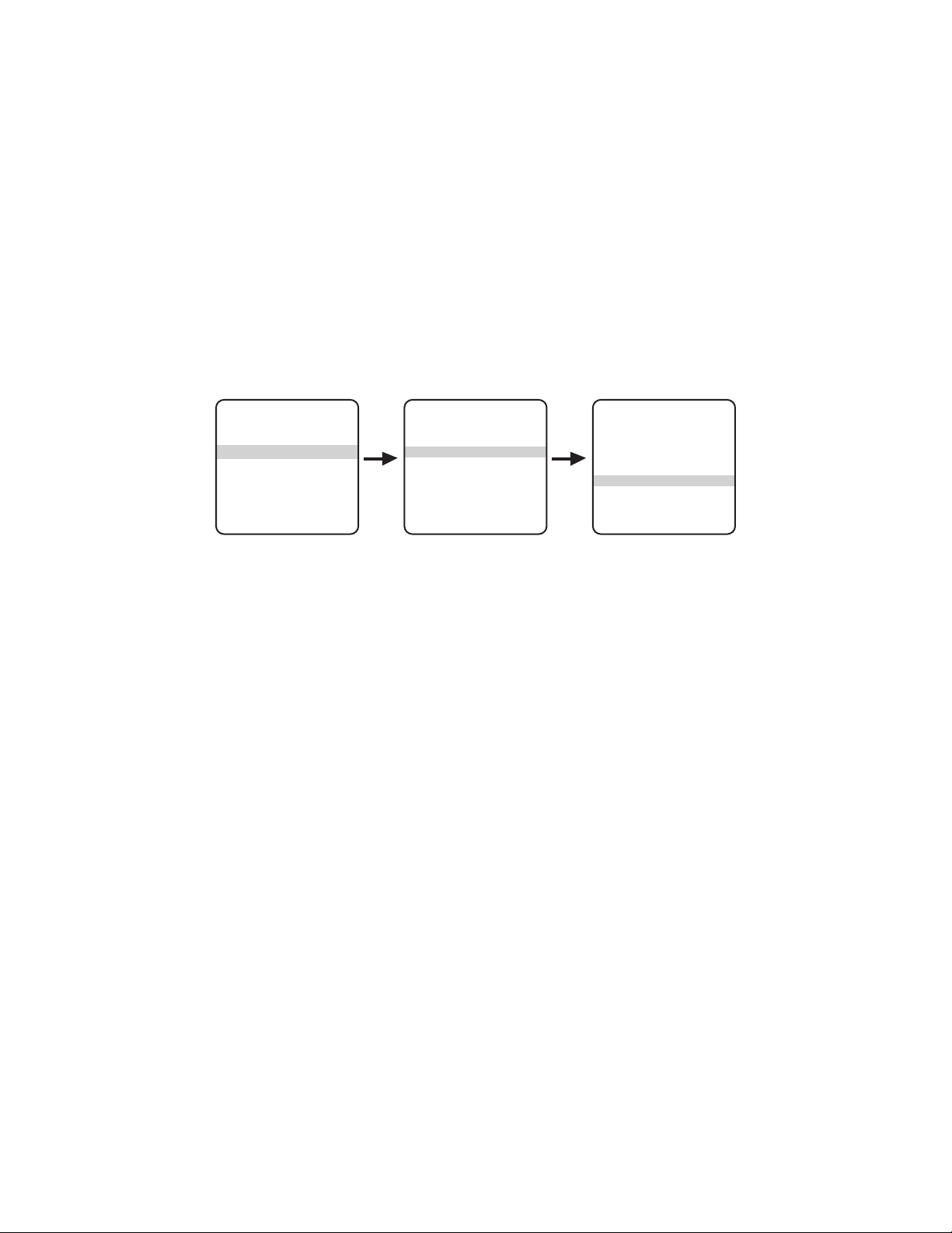
To configure the vertical label position for direction:
Set Azimuth Zero
Az/El Left
Az/El Line 10
Direction Right
Direction Line 10
Disp Duration 2
Exit
Az/El/Direction
Park Time 0
Power Up Default
Spd Profile 90 MPH Wind
<Az/El/Direction>
Exit
Other Menu
<Pan Limits>
<Tilt Limits>
<Camera>
<Other>
Exit
MAIN MENU
1. Call preset 95 (28). The main menu appears.
2. Position the cursor beside <Other>. Press the Iris Open button; the menu appears.
3. Position the cursor beside <Az/El/Direction>. Press the Iris Open button; the menu appears.
4. Position the cursor beside Direction Line. Press the Iris Open button; the cursor moves to the right.
5. Move the joystick up or down to view the available selections.
6. Do one of the following:
• Select: Press the Iris Open button to select the option.
• Cancel: Press the Iris Close button to retain the current setting.
DISPLAY DURATION
Display Duration configures the duration the Az/El and Direction labels are displayed on the monitor. The available settings for display duration
include the following:
• Cont: The label appears continuously.
• 2 (default): The label appears for 2 seconds after PTZ functions end.
• 5: The label appears for 5 seconds after PTZ functions end.
• 10: The label appears for 10 seconds after PTZ functions end.
To configure the display duration for the Az/El and Direction labels:
1. Call preset 95 (28). The main menu appears.
2. Position the cursor beside <Other>. Press the Iris Open button; the menu appears.
3. Position the cursor beside <Az/El/Direction>. Press the Iris Open button; the menu appears.
4. Position the cursor beside Disp Duration. Press the Iris Open button; the cursor moves to the right.
5. Move the joystick up or down to view the available selections.
6. Do one of the following:
• Select: Press the Iris Open button to select the option.
• Cancel: Press the Iris Close button to retain the current setting.
66 C1317M-C (8/13)

FACTORY RESET
<Pan Limits>
<Tilt Limits>
<Camera>
<Other>
Exit
MAIN MENU
Continue with Factory Reset?
No
Yes
Factory Reset
Park Time 0
Power Up Default
Spd Profile 90 MPH Wind
<Az/El/Direction>
<Factory Reset>
Exit
Other Menu
Factory Reset restores all analog menu settings to the original factory defaults.
To perform a factory reset:
1. Call preset 95 (28). The main menu appears.
2. Position the cursor beside <Other>. Press the Iris Open button; the menu appears.
3. Position the cursor beside <Factory Reset>. Press the Iris Open button; a message appears that reads "Continue with Factory Reset?"
4. Move the joystick up or down to position the cursor next to No (default) or Yes.
5. Do one of the following:
• Perform factory reset: Position the cursor next to Yes. Press the Iris Open button; the previous menu appears. After an approximate
five-second delay, all menus are refreshed to display the factory default settings.
• Cancel: Position the cursor next to No. Press the Iris Open button; the previous menu appears.
PAN LIMITS
MAIN MENU
<Pan Limits>
<Tilt Limits>
<Camera>
<Other>
Exit
When pan limits are set, a pan operation (joystick and pan/tilt keys) stops when a pan limit is reached. Pan limits can be set using controller
presets or using the Pan Limits menu.
NOTE: Limit stops are inactive while setting items in the menu (such as, azimuth zero and manual pan limits).
Turning Pan Limits On or Off
Pan limits must be turned on before they can be configured. Pan limits are set to OFF by default.
To change the pan limit mode:
1. Call preset 95 (28). The main menu appears.
2. Position the cursor beside <Pan Limits>. Press the Iris Open button; the menu appears.
3. Position the cursor beside Pan Limits. Press the Iris Open button; the cursor moves to the right.
Pan Limits Menu
Pan Limits Off
Set Pan Limits
Clear Pan Limits
Exit
4. Move the joystick up or down to switch between On and Off.
5. Do one of the following:
• Select: Press the Iris Open button to select the option.
• Cancel: Press the Iris Close button to retain the current setting.
C1317M-C (8/13) 67

Configuring Pan Limits Using Controller Presets
NOTE: Before using controller presets, refer to the documentation for your control system for information about configuring presets.
To configure pan limits using controller presets:
1. Enable pan limits (refer to Turning Pan Limits On or Off on page 67 above) and exit the menu.
2. Push the joystick left until the camera reaches the leftmost limit, or position, for the camera.
3. Call preset 90 (23). This is the left pan limit.
4. Push the joystick right until the camera reaches the rightmost limit, or position, for the camera.
5. Call preset 91 (24). This is the right pan limit.
If you set presets 90 (23) and 91 (24) to the same point, the camera disables pan limits.
When you call preset 90 (23), the pan limits are disabled until you call preset 91 (24).
Configuring Pan Limits Using the Pan Limits Menu
1. Call preset 95 (28). The main menu appears.
2. Position the cursor beside <Pan Limits>, and then press the Iris Open button. The menu appears.
3. Position the cursor beside Set Pan Limits. Press the Iris Open button. The message PRESS IRIS OPEN TO SET LEFT LIMIT appears.
4. Push the joystick left until the camera reaches the leftmost limit, or position, for the camera.
5. Press the Iris Open button. This is the left pan limit. The message PRESS IRIS OPEN TO SET RIGHT LIMIT appears.
6. Push the joystick right until the camera reaches the rightmost limit, or position, for the camera.
7. Press the Iris Open button. This is the right pan limit.
8. Exit the Pan Limits menu.
Clearing Pan Limits
1. Call preset 95 (28). The main menu appears.
2. Position the cursor beside <Pan Limits>, and then press the Iris Open button. The menu appears.
3. Position the cursor beside Clear Pan Limits. Press the Iris Open button; the cursor briefly changes to an asterisk (*) to show that the pan
limits have been disabled.
68 C1317M-C (8/13)

PARK TIME
MAIN MENU
<Pan Limits>
<Tilt Limits>
<Camera>
<Other>
Exit
Other Menu
Park Time 0
Power Up Default
Spd Profile 90 MPH Wind
Exit
Use this feature to park at the preset 1 position after a specific number of minutes of control inactivity. You can set this number from 1 minute to
720 minutes (12 hours), or you can set it to zero to disable this feature. The default is 0 (disabled).
NOTE: You must configure preset 1 for the system to use this feature.
To change the park time:
1. Call preset 95 (28). The main menu appears.
2. Position the cursor beside <Other>. Press the Iris Open button; the menu appears.
3. Position the cursor beside Park Time. Press the Iris Open button; the cursor moves to the right.
4. Move the joystick up or down to change the park time.
5. Do one of the following:
• Select: Press the Iris Open button to select the option.
• Cancel: Press the Iris Close button to retain the current setting.
POWER UP MODE
MAIN MENU
<Pan Limits>
<Tilt Limits>
<Camera>
<Other>
Exit
Use this feature to execute a specific set of commands following the power up sequence. You can select from the following options:
• Default: On power up, the system performs a configuration cycle and stops at zero reference, showing Configuration Done, address, and
mode settings on the screen.
• Park: The system moves to preset 1 after the configuration cycle ends. The only text on the screen is the preset label (if one is configured).
• Full Pat: The system initiates its configured pattern after the configuration cycle ends. The pattern length is 90 seconds.
• Half Pat 1: The system initiates the first half-pattern after the configuration cycle ends. The pattern length is 45 seconds.
• Half Pat 2: The system initiates the second half-pattern after the configuration cycle ends. The pattern length is 45 seconds.
To execute Full Pat, Half Pat 1, or Half Pat 2 upon power up, you must first configure the system with the appropriate pattern.
Other Menu
Park Time 0
Power Up Default
Spd Profile 90 MPH Wind
<Az/El/Direction>
Exit
C1317M-C (8/13) 69

To select the power up mode:
Park Time 0
Power Up Default
Spd Profile 90 MPH Wind
<Az/El/Direction>
Exit
Other Menu
<Pan Limits>
<Tilt Limits>
<Camera>
<Other>
Exit
MAIN MENU
1. Call preset 95 (28). The main menu appears.
2. Position the cursor beside <Power Up Mode>. Press the Iris Open button; the menu appears.
3. Position the cursor beside Power Up. Press the Iris Open button; the cursor moves to the right.
4. Move the joystick up or down to view the available selections.
5. Do one of the following:
• Select: Press the Iris Open button to select the option.
• Cancel: Press the Iris Close button to retain the current setting.
SPEED PROFILE
Use this feature to set the wind speed conditions for the location of the system. High winds may interfere with high speed turbo and preset
panning. The speed profile provides the best panning speed for the wind conditions. The maximum pan speed in regular (non-turbo) mode for
either wind speed profile is 40 degrees per second.
You can set two wind speed profiles:
• 50 MPH Wind: Turbo and preset pan speeds are 100 degrees per second. In low wind conditions, the system has enough torque to pan at
this higher speed.
• 90 MPH Wind (default): Turbo and preset pan speeds are 50 degrees per second. In high wind conditions, the system has enough torque
to pan at this lower speed.
NOTE: For more information about Turbo Mode, refer to Turbo Mode on page 59.
To set the speed profile:
1. Call preset 95 (28). The main menu appears.
2. Position the cursor beside <Other>. Press the Iris Open button; the menu appears.
3. Position the cursor beside Spd Profile. Press the Iris Open button; the cursor moves to the right.
4. Move the joystick up or down to switch between 50 MPH Wind and 90 MPH Wind.
5. Do one of the following:
• Select: Press the Iris Open button to select the option.
• Cancel: Press the Iris Close button to retain the current setting.
70 C1317M-C (8/13)

TILT LIMITS
MAIN MENU
<Pan Limits>
<Tilt Limits>
<Camera>
<Other>
Exit
Tilt Limits Menu
Tilt Limits Off
Set Tilt Limits
Clear Tilt Limits
Exit
When tilt limits are set, a tilt operation (joystick and pan/tilt keys) stops when a tilt limit is reached. Tilt limits can be set using controller presets
or using the Tilt Limits menu.
NOTE: Limit stops are inactive while setting items in the menu (such as, azimuth zero and manual pan limits).
Turning Tilt Limits On or Off
Tilt limits must be enabled before they can be configured. Tilt limits are set to OFF by default.
To change the tilt limit mode:
1. Call preset 95 (28). The main menu appears.
2. Position the cursor beside <Tilt Limits>. Press the Iris Open button; the menu appears.
3. Position the cursor beside Tilt Limits. Press the Iris Open button; the cursor moves to the right.
4. Move the joystick up or down to switch between On and Off.
5. Do one of the following:
• Select: Press the Iris Open button to select the option.
• Cancel: Press the Iris Close button to retain the current setting.
Configuring Tilt Limits Using Controller Presets
NOTE: Before using controller presets, refer to the documentation for your control system for information about configuring presets.
To configure tilt limits using controller presets:
1. Enable tilt limits (refer to Turning Pan Limits On or Off on page 67), and then exit the menu.
2. Push the joystick down until the camera reaches the lowest limit, or position, for the camera.
3. Call preset 92 (25). This is the lower tilt limit.
4. Push the joystick up until the camera reaches the highest limit, or position, for the camera.
5. Call preset 93 (26). This is the upper tilt limit.
If you set presets 92 (25) and 93 (26) to the same point, the camera disables tilt limits.
When you call preset 92 (25), the tilt limits are disabled until you call preset 93 (26).
C1317M-C (8/13) 71

Configuring Tilt Limits Using the Tilt Limits Menu
1. Call preset 95 (28). The main menu appears.
2. Position the cursor beside <Tilt Limits>. Press the Iris Open button; the menu appears.
3. Position the cursor beside Set Tilt Limits. Press the Iris Open button. The message PRESS IRIS OPEN TO SET LOWER LIMIT appears.
4. Push the joystick down until the camera reaches the lowest limit, or position, for the camera.
5. Press the Iris Open button. This is the lower tilt limit. The message PRESS IRIS OPEN TO SET UPPER LIMIT appears.
6. Push the joystick up until the camera reaches the highest limit, or position, for the camera.
7. Press the Iris Open button. This is the upper tilt limit.
8. Exit the Tilt Limits menu.
Clearing Tilt Limits
1. Call preset 95 (28). The main menu appears.
2. Position the cursor beside <Tilt Limits>. Press the Iris Open button; the menu appears.
3. Position the cursor beside Clear Tilt Limits. Press the Iris Open button; the cursor briefly changes to an asterisk (*) to show that the tilt limits
have been disabled.
ZONES
Follow these guidelines when configuring zones:
• Your controller must support zone operation.
• Refer to the documentation for your control system to configure zones.
• Set zones moving the joystick left to right. The left position is always the start position.
72 C1317M-C (8/13)

Specifications
THERMAL CAMERA/OPTICS
Detector Sun-safe, uncooled microbolometer, amorphous silicon
Array Format 640 x 480 or 384 x 288
Pixel Size
640 x 480 17 µm
384 x 288 25 µm
Effective Resolution 307,200 (640 x 480); 110,592 (384 x 288)
Spectral Response 7.5 to 13.5 µm, LWIR
Normalization Source Internal shutter (offset only), 0.3 second video freeze during shutter
Temporal NETD 50 mK at f/1.0
Display Formats White hot, black hot, and rainbow
LENS
Lens (mm) F-Number (f)
35 1.4 18° x 13° x 22°
50 1.2 12° x 9° x 15°
100 1.4 6° x 5° x 8°
14.25 1.2 39° x 29° x 48°
35 1.4 16° x 12° x 19°
50 1.7 11° x 8° x 14°
100 1.6 6° x 4° x 7°
640 x 480 Resolution
Field of View
(H/V/D)
384 x 288 Resolution
VIDEO
IP/Network
Video Encoding H.264 High, Main, or Base profiles; MJPEG, and JPEG.
Video Streams Up to 2 simultaneous streams; the second stream is variable based on the setup of the primary stream
Frame Rate* Up to 30, 25, 24, 15, 12.5, 12, 10, 8, 7.5, 6, 5, 4, 3, 2.5, 2, 1 (dependent upon stream configuration)
Available Resolutions 640 x 480 and 384 x 288
Supported Protocols TCP/IP, UDP/IP (Unicast, Multicast IGMP), UPnP, DNS, DHCP, RTP, RTSP, NTP, IPv4, IPv6
HTTPS, LDAP (client), SSH, SSL, SMTP, FTP, and 802.1x (EAP)
Users
Unicast Up to 20 simultaneous users depending on resolution settings (2 guaranteed streams)
Multicast Unlimited users H.264
Security Access Password protected
Software Interface Web browser view and setup
Pelco System Integration Endura 2.0 (or later); Digital Sentry
®
4.2 (or later)
Analog
Video/Coaxitron Port 75 ohms, unbalanced
Video Modes NTSC or PAL
Video Level 1 Vp-p
*Some models are limited to 8.33 ips to comply with US government export control regulations.
†
Supports mixed IPv4 and IPv6 installations, but not IPv6-only deployments.
†
, SNMP, QoS, HTTP,
C1317M-C (8/13) 73

ELECTRICAL
Ethernet Port Inline RJ-45 for 100Base-TX, auto MDI/MDI-X
Ethernet Cabling Required Cat5 or better for 100Base-TX
Input Power 24/120/230 VAC, 50/60 Hz, switch selectable for 120/230 VAC
Input Power Range +15%/–20%
Lens Power Consumption
14.25, 30, 50 mm 5.0 A, 120 VA (110 W)
100 mm 6.5 A, 160 VA (150)
24 VAC Fuse 8.0 A, slow-blow
120/230 VAC Fuse 2 A, slow-blow
Heater Thermostat controlled
Local Storage Micro SD
Alarm Inputs N.O. switch, N.C. switch, or 1 kohm; supervised
Mechanical Relay Output*
Voltage 60 VDC, 125 VAC
Current 1 A
Power 62.5 VA, 30 W
Solid-State Relay Output*
Voltage 32 V
Current 100 mA
Power (N/A)
Audio
Input UTP 600 ohm mono, 12 VDC power source, line level/external microphone input, 1 Vp-p maximum
signal level
Compression G.711 PCM, 64 kbps
Serial Control Port 4-wire, RS-422/RS-485 (Pelco D or Pelco P)
Serial Control Cabling Type UTP
*Assumes maximum operating capacity.
MECHANICAL
Pan Movement 360° continuous pan rotation
Vertical Tilt 33° to –79° unobstructed from horizontal
Variable Pan/Tilt Speed Analog Control IP Control
Pan 0.5° to 40°/sec, 100°/sec turbo 0.1° to 100°/sec
Tilt 0.5° to 20°/sec 0.1° to 30°/sec
Preset Speeds
Pan 100° per second
Tilt 30° per second
Access Cover 2 captive Torx
™
screws
74 C1317M-C (8/13)

GENERAL
19.71
(7.76)
25.91
(10.20)
23.32
(9.18)
57.15
(22.50)
12.57
(4.95)
Construction Aluminum
Finish Gray polyester powder coat
Environment Indoor/outdoor
Operating Temperature –40° to 50°C (–40° to 122°F)
Storage Temperature –40° to 60°C (–40° to 140°F)
Weight
ESTI314-2N/5N 11.2 kg (24.6 lb)
ESTI314-2W/5W 11.8 kg (26.1 lb)
ESTI335-2N/5N 11.3 kg (24.9 lb)
ESTI335-2W/5W 12.0 kg (26.4 lb)
ESTI350-2N/5N 11.3 kg (25.0 lb)
ESTI350-2W/5W 12.0 kg (26.5 lb)
ESTI3100-2N/5N 11.4 kg (25.2 lb)
ESTI3100-2W/5W 12.1 kg (26.7 lb)
ESTI635-2N/5N 11.3 kg (24.9 lb)
ESTI635-2W/5W 12.0 kg (26.4 lb)
ESTI650-2N/5N 11.3 kg (25.0 lb)
ESTI650-2W/5W 12.0 kg (26.5 lb)
ESTI6100-2N/5N 11.4 kg (25.2 lb)
ESTI6100-2W/5W 12.1 kg (26.7 lb)
NOTE: VALUES IN PARENTHESES ARE INCHES; ALL OTHERS ARE CENTIMETERS.
Figure 18. Pedestal Mount Models
C1317M-C (8/13) 75

NOTE: VALUES IN PARENTHESES ARE INCHES; ALL OTHERS ARE CENTIMETERS.
12.06
(4.75)
13.97
(5.50)
2.54 X 0.95
(1.0 X 0.375)
12.57
(4.95)
60.07
(23.65)
19.71
(7.76)
25.91
(10.20)
Figure 19. Wall Mount Models
12.06
(4.75)
Ø 2.03 X 0.95
(0.8 X 0.375)
Ø 0.381 (0.150) 3X
7.62 (3.00) B.C.
Ø 3.81
(1.50)
Figure 20. Pedestal Mounting Pattern
15.24
(6.00)
32.49
(12.79)
Figure 21. Wall Mounting Pattern
76 C1317M-C (8/13)

Appendix
*SW1-3 and SW1-4 are not used; set them to the OFF position.
Switch Number
†
Turning on the Coaxitron receiver without 75 ohm termination of the analog video output will cause loss of control of the pan/tilt operation and
random movements of the pan/tilt motors.
Table G. Switch Settings for SW1-1 to SW1-4
Baud Rate Settings
Switch Number
2400 4800 9600
SW1-1 OFF ON OFF
SW1-2 OFF OFF ON
SW1-3 OFF* OFF* OFF*
SW1-4 OFF* OFF* OFF*
Table H. Switch Settings for SW1-5 to SW1-8
Settings
OFF ON
SW1-5 For controllers that have more than 32 presets. For American Dynamics controllers (32 presets).
SW1-6 For CM9502 with fixed speed keyboards. For CM9502 with variable speed keyboard.
SW1-7 Coaxitron receiver is off; analog video does not
require a 75 ohm termination.
Coaxitron receiver is on; analog video must be
terminated with a 75 ohm load.
†
SW1-8 1.2 Vp-p video level 1.0 Vp-p video level
C1317M-C (8/13) 77

NOTE: The Esprit will sense and automatically select input from Coaxitron control signals in either the standard or extended mode. Therefore, the DIP
switches settings have no effect on Coaxitron control signals.
Table I. Switch Settings for SW2 (1 of 6)
Receiver Address
P- Ty pe D-Ty p e
Control Control
SW2-1 SW2-2 SW2-3 SW2-4 S W2-5 SW2-6 SW2-7 SW2-8
1 – OFF OFF OFF OFF OFF OFF OFF OFF
2 1 ON OFF OFF OFF OFF OFF OFF OFF
3 2 OFF ON OFF OFF OFF OFF OFF OFF
4 3 ON ON OFF OFF OFF OFF OFF OFF
5 4 OFF OFF ON OFF OFF OFF OFF OFF
6 5 ON OFF ON OFF OFF OFF OFF OFF
7 6 OFF ON ON OFF OFF OFF OFF OFF
8 7 ON ON ON OFF OFF OFF OFF OFF
9 8 OFF OFF OFF ON OFF OFF OFF OFF
10 9 ON OFF OFF ON OFF OFF OFF OFF
11 10 OFF ON OFF ON OFF OFF OFF OFF
12 11 ON ON OFF ON OFF OFF OFF OFF
13 12 OFF OFF ON ON OFF OFF OFF OFF
14 13 ON OFF ON ON OFF OFF OFF OFF
15 14 OFF ON ON ON OFF OFF OFF OFF
16 15 ON ON ON ON OFF OFF OFF OFF
17 16 OFF OFF OFF OFF ON OFF OFF OFF
18 17 ON OFF OFF OFF ON OFF OFF OFF
19 18 OFF ON OFF OFF ON OFF OFF OFF
20 19 ON ON OFF OFF ON OFF OFF OFF
21 20 OFF OFF ON OFF ON OFF OFF OFF
22 21 ON OFF ON OFF ON OFF OFF OFF
23 22 OFF ON ON OFF ON OFF OFF OFF
24 23 ON ON ON OFF ON OFF OFF OFF
25 24 OFF OFF OFF ON ON OFF OFF OFF
26 25 ON OFF OFF ON ON OFF OFF OFF
27 26 OFF ON OFF ON ON OFF OFF OFF
28 27 ON ON OFF ON ON OFF OFF OFF
29 28 OFF OFF ON ON ON OFF OFF OFF
30 29 ON OFF ON ON ON OFF OFF OFF
31 30 OFF ON ON ON ON OFF OFF OFF
32 31 ON ON ON ON ON OFF OFF OFF
– 32 OFF OFF OFF OFF OFF ON OFF OFF
– 33 ON OFF OFF OFF OFF ON OFF OFF
– 34 OFF ON OFF OFF OFF ON OFF OFF
– 35 ON ON OFF OFF OFF ON OFF OFF
– 36OFFOFFONOFFOFFONOFFOFF
– 37 ON OFF ON OFF OFF ON OFF OFF
– 38 OFF ON ON OFF OFF ON OFF OFF
– 39 ONON ONOFFOFFONOFFOFF
– 40 OFF OFF OFF ON OFF ON OFF OFF
– 41 ON OFF OFF ON OFF ON OFF OFF
– 42 OFF ON OFF ON OFF ON OFF OFF
– 43 ONONOFFONOFFONOFFOFF
– 44 OFF OFF ON ON OFF ON OFF OFF
– 45 ON OFF ON ON OFF ON OFF OFF
– 46 OFF ON ON ON OFF ON OFF OFF
– 47ONONONONOFFONOFFOFF
– 48 OFF OFF OFF OFF ON ON OFF OFF
– 49 ON OFF OFF OFF ON ON OFF OFF
– 50 OFF ON OFF OFF ON ON OFF OFF
– 51 ONONOFFOFFON ONOFFOFF
– 52 OFF OFF ON OFF ON ON OFF OFF
– 53 ON OFF ON OFF ON ON OFF OFF
– 54 OFF ON ON OFF ON ON OFF OFF
– 55 ON ON ON OFF ON ON OFF OFF
Switch Setting
Table I. Switch Settings for SW2 (2 of 6)
Receiver Address
P-Type D-Type
Control Control
SW2-1 SW2-2 SW2-3 SW2-4 SW2-5 SW2-6 SW2-7 SW2-8
– 56 OFF OFF OFF ON ON ON OFF OFF
– 57ONOFFOFFONONONOFFOFF
– 58 OFF ON OFF ON ON ON OFF OFF
– 59 ON ON OFF ON ON ON OFF OFF
– 60OFFOFFONONONONOFFOFF
– 61 ON OFF ON ON ON ON OFF OFF
– 62 OFF ON ON ON ON ON OFF OFF
– 63ONONONONONONOFFOFF
– 64 OFF OFF OFF OFF OFF OFF ON OFF
– 65 ON OFF OFF OFF OFF OFF ON OFF
– 66 OFF ON OFF OFF OFF OFF ON OFF
– 67 ON ON OFF OFF OFF OFF ON OFF
– 68 OFF OFF ON OFF OFF OFF ON OFF
– 69 ON OFF ON OFF OFF OFF ON OFF
– 70 OFF ON ON OFF OFF OFF ON OFF
– 71 ON ON ON OFF OFF OFF ON OFF
– 72 OFF OFF OFF ON OFF OFF ON OFF
– 73 ONOFFOFFONOFFOFFONOFF
– 74 OFF ON OFF ON OFF OFF ON OFF
– 75 ON ON OFF ON OFF OFF ON OFF
– 76 OFF OFF ON ON OFF OFF ON OFF
– 77 ON OFF ON ON OFF OFF ON OFF
– 78 OFF ON ON ON OFF OFF ON OFF
– 79ONONONONOFFOFFONOFF
– 80 OFF OFF OFF OFF ON OFF ON OFF
– 81 ON OFF OFF OFF ON OFF ON OFF
– 82 OFF ON OFF OFF ON OFF ON OFF
– 83 ON ON OFF OFF ON OFF ON OFF
– 84 OFF OFF ON OFF ON OFF ON OFF
– 85 ONOFFONOFFONOFFONOFF
– 86 OFF ON ON OFF ON OFF ON OFF
– 87 ONON ONOFFONOFFONOFF
– 88 OFF OFF OFF ON ON OFF ON OFF
– 89 ONOFFOFFONONOFFONOFF
– 90 OFF ON OFF ON ON OFF ON OFF
– 91 ON ON OFF ON ON OFF ON OFF
– 92 OFF OFF ON ON ON OFF ON OFF
– 93 ON OFF ON ON ON OFF ON OFF
– 94 OFF ON ON ON ON OFF ON OFF
– 95ONONONONONOFFONOFF
– 96 OFF OFF OFF OFF OFF ON ON OFF
– 97 ON OFF OFF OFF OFF ON ON OFF
– 98 OFF ON OFF OFF OFF ON ON OFF
– 99 ON ON OFF OFF OFF ON ON OFF
– 100 OFF OFF ON OFF OFF ON ON OFF
– 101 ON OFF ON OFF OFF ON ON OFF
– 102 OFF ON ON OFF OFF ON ON OFF
– 103 ON ON ON OFF OFF ON ON OFF
– 104 OFF OFF OFF ON OFF ON ON OFF
– 105 ON OFF OFF ON OFF ON ON OFF
– 106 OFF ON OFF ON OFF ON ON OFF
– 107 ON ON OFF ON OFF ON ON OFF
– 108 OFF OFF ON ON OFF ON ON OFF
– 109 ON OFF ON ON OFF ON ON OFF
– 110 OFF ON ON ON OFF ON ON OFF
– 111 ON ON ON ON OFF ON ON OFF
Switch Setting
78 C1317M-C (8/13)

Table I. Switch Settings for SW2 (3 of 6)
Receiver Address
P- Ty pe D-Ty p e
Control Control
SW2-1 SW2-2 SW2-3 SW2-4 S W2-5 SW2-6 SW2-7 SW2-8
– 112 OFF OFF OFF OFF ON ON ON OFF
– 113 ON OFF OFF OFF ON ON ON OFF
– 114 OFF ON OFF OFF ON ON ON OFF
– 115 ON ON OFF OFF ON ON ON OFF
– 116 OFF OFF ON OFF ON ON ON OFF
– 117 ON OFF ON OFF ON ON ON OFF
– 118 OFF ON ON OFF ON ON ON OFF
– 119 ON ON ON OFF ON ON ON OFF
– 120 OFF OFF OFF ON ON ON ON OFF
– 121 ON OFF OFF ON ON ON ON OFF
– 122 OFF ON OFF ON ON ON ON OFF
– 123 ON ON OFF ON ON ON ON OFF
– 124 OFF OFF ON ON ON ON ON OFF
– 125 ON OFF ON ON ON ON ON OFF
–126OFFONONONONONONOFF
– 127 ON ON ON ON ON ON ON OFF
– 128 OFF OFF OFF OFF OFF OFF OFF ON
– 129 ON OFF OFF OFF OFF OFF OFF ON
– 130 OFF ON OFF OFF OFF OFF OFF ON
– 131 ON ON OFF OFF OFF OFF OFF ON
– 132 OFF OFF ON OFF OFF OFF OFF ON
– 133 ON OFF ON OFF OFF OFF OFF ON
– 134 OFF ON ON OFF OFF OFF OFF ON
– 135 ON ON ON OFF OFF OFF OFF ON
– 136 OFF OFF OFF ON OFF OFF OFF ON
– 137 ON OFF OFF ON OFF OFF OFF ON
– 138 OFF ON OFF ON OFF OFF OFF ON
– 139 ON ON OFF ON OFF OFF OFF ON
– 140 OFF OFF ON ON OFF OFF OFF ON
– 141 ON OFF ON ON OFF OFF OFF ON
– 142 OFF ON ON ON OFF OFF OFF ON
– 143 ON ON ON ON OFF OFF OFF ON
– 144 OFF OFF OFF OFF ON OFF OFF ON
– 145 ON OFF OFF OFF ON OFF OFF ON
– 146 OFF ON OFF OFF ON OFF OFF ON
– 147 ON ON OFF OFF ON OFF OFF ON
– 148 OFF OFF ON OFF ON OFF OFF ON
– 149 ON OFF ON OFF ON OFF OFF ON
– 150 OFF ON ON OFF ON OFF OFF ON
– 151 ON ON ON OFF ON OFF OFF ON
– 152 OFF OFF OFF ON ON OFF OFF ON
– 153 ON OFF OFF ON ON OFF OFF ON
– 154 OFF ON OFF ON ON OFF OFF ON
– 155 ON ON OFF ON ON OFF OFF ON
– 156 OFF OFF ON ON ON OFF OFF ON
– 157 ON OFF ON ON ON OFF OFF ON
– 158 OFF ON ON ON ON OFF OFF ON
– 159 ON ON ON ON ON OFF OFF ON
– 160 OFF OFF OFF OFF OFF ON OFF ON
– 161 ON OFF OFF OFF OFF ON OFF ON
– 162 OFF ON OFF OFF OFF ON OFF ON
– 163 ON ON OFF OFF OFF ON OFF ON
– 164 OFF OFF ON OFF OFF ON OFF ON
– 165 ON OFF ON OFF OFF ON OFF ON
– 166 OFF ON ON OFF OFF ON OFF ON
– 167 ON ON ON OFF OFF ON OFF ON
– 168 OFF OFF OFF ON OFF ON OFF ON
– 169 ON OFF OFF ON OFF ON OFF ON
– 170 OFF ON OFF ON OFF ON OFF ON
– 171 ON ON OFF ON OFF ON OFF ON
Switch Setting
Table I. Switch Settings for SW2 (4 of 6)
Receiver Address
P-Type D-Type
Control Control
SW2-1 SW2-2 SW2-3 SW2-4 SW2-5 SW2-6 SW2-7 SW2-8
– 172 OFF OFF ON ON OFF ON OFF ON
– 173 ON OFF ON ON OFF ON OFF ON
– 174 OFF ON ON ON OFF ON OFF ON
– 175 ON ON ON ON OFF ON OFF ON
– 176 OFF OFF OFF OFF ON ON OFF ON
– 177 ON OFF OFF OFF ON ON OFF ON
– 178 OFF ON OFF OFF ON ON OFF ON
– 179 ON ON OFF OFF ON ON OFF ON
– 180 OFF OFF ON OFF ON ON OFF ON
– 181 ON OFF ON OFF ON ON OFF ON
– 182 OFF ON ON OFF ON ON OFF ON
– 183 ON ON ON OFF ON ON OFF ON
– 184 OFF OFF OFF ON ON ON OFF ON
– 185 ON OFF OFF ON ON ON OFF ON
– 186 OFF ON OFF ON ON ON OFF ON
– 187 ON ON OFF ON ON ON OFF ON
– 188 OFF OFF ON ON ON ON OFF ON
– 189 ON OFF ON ON ON ON OFF ON
– 190 OFF ON ON ON ON ON OFF ON
– 191 ON ON ON ON ON ON OFF ON
– 192 OFF OFF OFF OFF OFF OFF ON ON
– 193 ON OFF OFF OFF OFF OFF ON ON
– 194 OFF ON OFF OFF OFF OFF ON ON
– 195 ON ON OFF OFF OFF OFF ON ON
– 196 OFF OFF ON OFF OFF OFF ON ON
– 197 ON OFF ON OFF OFF OFF ON ON
– 198 OFF ON ON OFF OFF OFF ON ON
– 199 ON ON ON OFF OFF OFF ON ON
– 200 OFF OFF OFF ON OFF OFF ON ON
– 201 ON OFF OFF ON OFF OFF ON ON
– 202 OFF ON OFF ON OFF OFF ON ON
– 203 ON ON OFF ON OFF OFF ON ON
– 204 OFF OFF ON ON OFF OFF ON ON
– 205 ON OFF ON ON OFF OFF ON ON
– 206 OFF ON ON ON OFF OFF ON ON
– 207 ON ON ON ON OFF OFF ON ON
– 208 OFF OFF OFF OFF ON OFF ON ON
– 209 ON OFF OFF OFF ON OFF ON ON
– 210 OFF ON OFF OFF ON OFF ON ON
– 211 ON ON OFF OFF ON OFF ON ON
– 212 OFF OFF ON OFF ON OFF ON ON
– 213 ON OFF ON OFF ON OFF ON ON
– 214 OFF ON ON OFF ON OFF ON ON
– 215 ON ON ON OFF ON OFF ON ON
– 216 OFF OFF OFF ON ON OFF ON ON
– 217 ON OFF OFF ON ON OFF ON ON
– 218 OFF ON OFF ON ON OFF ON ON
– 219 ON ON OFF ON ON OFF ON ON
– 220 OFF OFF ON ON ON OFF ON ON
– 221 ON OFF ON ON ON OFF ON ON
– 222 OFF ON ON ON ON OFF ON ON
– 223 ON ON ON ON ON OFF ON ON
– 224 OFF OFF OFF OFF OFF ON ON ON
– 225 ON OFF OFF OFF OFF ON ON ON
– 226 OFF ON OFF OFF OFF ON ON ON
– 227 ON ON OFF OFF OFF ON ON ON
– 228 OFF OFF ON OFF OFF ON ON ON
– 229 ON OFF ON OFF OFF ON ON ON
– 230 OFF ON ON OFF OFF ON ON ON
– 231 ON ON ON OFF OFF ON ON ON
Switch Setting
C1317M-C (8/13) 79

Table I. Switch Settings for SW2 (5 of 6)
Receiver Address
P- Ty pe D-Ty p e
Control Control
SW2-1 SW2-2 SW2-3 SW2-4 S W2-5 SW2-6 SW2-7 SW2-8
– 232 OFF OFF OFF ON OFF ON ON ON
– 233 ON OFF OFF ON OFF ON ON ON
– 234 OFF ON OFF ON OFF ON ON ON
– 235 ON ON OFF ON OFF ON ON ON
– 236 OFF OFF ON ON OFF ON ON ON
– 237 ON OFF ON ON OFF ON ON ON
– 238 OFF ON ON ON OFF ON ON ON
– 239 ON ON ON ON OFF ON ON ON
– 240 OFF OFF OFF OFF ON ON ON ON
– 241 ON OFF OFF OFF ON ON ON ON
– 242 OFF ON OFF OFF ON ON ON ON
– 243 ON ON OFF OFF ON ON ON ON
Switch Setting
Table I. Switch Settings for SW2 (6 of 6)
Receiver Address
P-Type D-Type
Control Control
SW2-1 SW2-2 SW2-3 SW2-4 SW2-5 SW2-6 SW2-7 SW2-8
– 244 OFF OFF ON OFF ON ON ON ON
– 245 ON OFF ON OFF ON ON ON ON
– 246 OFF ON ON OFF ON ON ON ON
– 247 ON ON ON OFF ON ON ON ON
– 248 OFF OFF OFF ON ON ON ON ON
– 249 ON OFF OFF ON ON ON ON ON
– 250 OFF ON OFF ON ON ON ON ON
– 251 ON ON OFF ON ON ON ON ON
– 252 OFF OFF ON ON ON ON ON ON
–253ONOFFONONONONONON
–254OFFONONONONONONON
– 255 ON ON ON ON ON ON ON ON
Switch Setting
80 C1317M-C (8/13)

WARRANTY STATEMENT
For information about Pelco’s product warranty and thereto related information, refer to www.pelco.com/warranty.
This equipment contains electrical or electronic components that must be recycled properly to comply with Directive 2002/96/EC of the European Union
regarding the disposal of waste electrical and electronic equipment (WEEE). Contact your local dealer for procedures for recycling this equipment.
REVISION HISTORY
Manual # Date Comments
C1317M 8/11 Original version.
C1317M-A 8/12 Revised for the 1.8.2 firmware release.
C1317M-B 9/12 Removed references to zoom and focus features; these features are unavailable in Sarix TI products.
C1317M-C 8/13 Revised for the Sarix 1.9 firmware release.
Pelco, the Pelco logo, and other trademarks associa ted with Pelco products referred to in this publication are trademarks of Pelco, Inc. or its affilia tes. © Copyright 2013, Pelco, Inc.
ONVIF and the ONVIF logo are trademarks of ONVIF Inc. All other product names and services are the property of their respective companies. All rights reserved.
Product specifications and availability are subject to change without notice.

Pelco by Schneider Electric 3500 Pelco Way Clovis, California 93612-5699 United States
USA & Canada Tel (800) 289-9100 Fax (800) 289-9150
International Tel +1 (559) 292-1981 Fax +1 (559) 348-1120
www.pelco.com www.pelco.com/community
 Loading...