

Page 1

Caution
Remove
this page
and keep
it in a
secure
place.
®
C681M-A-LB (9/01)
3500 Pelco Way
Clovis, CA 93612 USA
North America and Canada
Tel 800/289-9100
FAX 800/289-9150
DataFAX 800/289-9108
International
Tel +1 559/292-1981
FAX +1 559/348-1120
DataFAX +1 559/292-0435
PelcoEurope BV
Tel +31 40/251-9870
FAX +31 40/251-9835
www.pelco.com
The DX3000 Series DVR has an unmarked lock
button to restrict unauthorized use of the recorder. The lock button will work only as long as
no one discovers its function. Since you may
need to make the manual accessible to others,
the lock button’s location and operation are NOT
documented in the manual – this is the only place
it is shown.
If you want to keep this page in the manual, just
staple it inside the cover.
The lock button is located on the front panel
below the PRE ALARM REC light.
SIMPLE LOCK
When the LOCK button is pressed (with a ballpoint pen, for example), the front panel controls
are disabled except for the CAMERA, SPLIT/
SEQUENCE, and ZOOM buttons. The LOCK
indicator light illuminates when the unit is in the
Lock mode. Press the LOCK button again to exit
the Lock mode.
The simple lock function does not work if a password has been entered into the recorder (refer
to Password Lock).
PASSWORD LOCK
Pressing the LOCK button on the front of the
unit lets you record a password. Once the password has been entered and the unit has been
locked, the front panel controls are disabled
except for the CAMERA, SPLIT/SEQUENCE,
and ZOOM buttons.
Entering Initial Password
1. Press the LOCK button for five seconds.
The Password Setting menu appears.
2. Enter a four-digit password. The password
may consist of the numbers 0-9. 1-9 are assigned to the camera buttons on the front of
the unit. 0 is assigned to the ZOOM key.
3. Turn the SHUTTLE ring to the right to enter
the password.
4. Re-enter the password, and then turn the
SHUTTLE ring to the right. The password is
now set, and the normal operating screen
appears.
If the wrong password is entered, “PASSWORD ERROR” appears on the screen, and
the password is cleared. Turn the SHUTTLE
ring to the left to exit the menu. Press the
LOCK button to turn off the indicator light.
Return to step 1.
Changing Password
1. Turn the Password Lock feature OFF (refer to
Turning Password Lock On and Off).
2. Press the LOCK button for five seconds.
The Password Lock menu appears.
3. Enter the current password, and then turn the
SHUTTLE ring to the right. The Password
Setting menu appears.
4. Using the same procedure for setting the
original password, enter and set the new
password.
Password Error
If you are asked to enter a password and you
enter the wrong one, press the WARNING RESET button to clear the incorrect password.
Turning Password Lock On and Off
OFF: To disable the Password Lock feature,
press the LOCK button, enter the password, and
turn the SHUTTLE ring to the right.
ON: To return to locked status, press the LOCK
button again.
Erasing the Password
If you no longer need a password, or if you forget your password, the current password can be
erased.
1. Press and hold the INFO and SET UP buttons on the front of the recorder. Press the
RESET button on the back of the unit, and
then release the INFO and SET UP buttons.
The unit begins a self-test.
2. When the self-test is complete, press the
RESET button again. The unit turns itself off.
3. Turn on the power.
4. Reset the time and date.
Page 2
®
DX3000 Series
Digital Recorder
Installation/
Operation Manual
C681M-D (2/02)
U
®
L
LISTED
Pelco • 3500 Pelco Way • Clovis, CA 93612-5699 USA • Pelco Online @ www.pelco.com
In North America and Canada: Tel (800) 289-9100 • FAX (800) 289-9150 • DataFAX (800) 289-9108
International Customers: Tel +1(559) 292-1981 • FAX +1(559) 348-1120 • DataFAX +1(559) 292-0435
PelcoEurope BV • Dillenburg Center, Dillenburgstraat 7C • 5652 AM Eindhoven • The Netherlands
Tel +31(40) 251-9870 • FAX +31(40) 251-9835
Page 3

CONTENTS
Section Page
IMPORTANT SAFEGUARDS AND WARNINGS................................................................5
OVERVIEW ........................................................................................................................6
DESCRIPTION...........................................................................................................6
MODELS ....................................................................................................................7
FRONT PANEL CONTROLS .....................................................................................7
REAR PANEL CONNECTORS .................................................................................10
INSTALLATION .................................................................................................................12
ADDING OR REMOVING A COPY OR ARCHIVE DEVICE .....................................16
ADDING A HARD DRIVE(S) .....................................................................................16
REMOVING A HARD DRIVE(S)................................................................................17
CONFIRMING THAT A DEVICE IS CONNECTED ...................................................17
BOOT-UP DELAY .....................................................................................................17
PROGRAMMING ..............................................................................................................18
ALARMS ...................................................................................................................22
IMAGE QUALITY ..............................................................................................22
MAXIMUM RECORDING FIELDS ....................................................................22
DEFINE GROUP SETTING .............................................................................. 23
ALARM RECORDING DURATION ...................................................................24
RECORD ALARM .............................................................................................24
PRE-ALARM RECORDING ..............................................................................25
M-DET SETTING ..............................................................................................26
ARCHIVE POINTER RESET .................................................................................... 26
ARCHIVE .................................................................................................................. 26
DATA .................................................................................................................26
OVERWRITE ....................................................................................................27
AUDIO RECORDING................................................................................................28
AUTO EJECT............................................................................................................28
BUZZER....................................................................................................................29
CALL OUT................................................................................................................. 30
CAPACITY REMAINING ...........................................................................................30
DATA CLEAR (ERASE) SELECTION .......................................................................31
FIFO/OVERWRITE MODE (DX3016 Models Only) ..................................................32
BACKUP FOLLOWING A POWER FAILURE ...................................................32
HARD DISK DRIVE (HDD) FULL..............................................................................33
HARD DISK DRIVE (HDD) REPEAT PLAYBACK.....................................................34
IM-CHECK MODE.....................................................................................................34
INITIALIZE MENUS ..................................................................................................35
MODE OUT...............................................................................................................35
MOTION DETECTION ..............................................................................................36
MULTIPLEXER DISPLAY .........................................................................................38
SPLIT SCREEN SETTING (DX3009 Models Only) ..........................................38
Nine-Camera (Split 9) Setting ...................................................................38
Four-Camera (Split 4) Setting ...................................................................39
SCREEN SWITCH PATTERN (DX3016 Models Only) .....................................39
SPLIT 4 SCREEN SETTING (DX3016 Models Only) .......................................40
SPLIT 9 SCREEN SETTING (DX3016 Models Only) .......................................40
SPLIT 16 SCREEN SETTING (DX3016 Models Only) .....................................41
IMAGE QUALITY ..............................................................................................41
SEQUENCE ......................................................................................................42
CHANNEL TITLE (Displaying Camera Title and/or Number)............................42
ALARM DISPLAY..............................................................................................43
CAMERA TITLE ................................................................................................44
POWER FAILURE.....................................................................................................44
RECORD...................................................................................................................44
IMAGE QUALITY ..............................................................................................44
MAXIMUM RECORDING FIELDS ....................................................................45
SELECT RECORDING MODE .........................................................................46
DEFINE GROUP............................................................................................... 46
RS-232C COMMUNICATION ...................................................................................47
SAVING MENU SETTINGS ......................................................................................48
SAVING MENU DATA .......................................................................................48
RESTORING MENU DATA ...............................................................................48
2 Pelco Manual C681M-D (2/02)
Page 4

TCP/IP SETTING (DX3016 Models Only).................................................................49
TIME AND DATE DISPLAY .......................................................................................49
DISPLAY MODE ...............................................................................................49
CHARACTER SIZE........................................................................................... 50
CLOCK LOCATION...........................................................................................51
TIME AND DATE SETTING ......................................................................................51
TIMER RECORDING ................................................................................................52
MOTION DETECTION DURING A TIMER RECORDING
(DX3016 Models Only)...................................................................................... 55
ESTIMATING RECORDING TIME....................................................................56
OPERATION .....................................................................................................................57
VIEWING CAMERAS................................................................................................58
SPLIT/SEQUENCE BUTTON ...........................................................................58
ZOOM BUTTONS .............................................................................................59
REMOTE VIEWING ..........................................................................................59
RECORDING ............................................................................................................59
BASIC RECORDING ........................................................................................59
ALARM RECORDING....................................................................................... 60
TIMER RECORDING ........................................................................................61
PLAYBACK ............................................................................................................... 61
BASIC PLAYBACK............................................................................................61
FRAME-BY-FRAME (STILL FRAME) PLAYBACK............................................62
PAUSE PLAYBACK ..........................................................................................62
REVERSE PLAYBACK .....................................................................................62
ADJUSTING PLAYBACK SPEED.....................................................................62
Regular Playback Mode............................................................................62
Still-Frame Playback Mode .......................................................................63
Shuttle Hold ..............................................................................................63
CHANGING PLAYBACK INTERVAL.................................................................63
FAST FORWARD/REWIND ..............................................................................63
SEARCHING..................................................................................................... 63
Time and Date Search ..............................................................................63
Index Search.............................................................................................64
Skip Search...............................................................................................65
Alarm List Search......................................................................................66
Jump to Starting Point...............................................................................66
PLAYBACK ON ANOTHER DEVICE ................................................................67
BACKING UP DATA.................................................................................................. 67
USING THE ARCHIVE BUTTON ......................................................................67
Start Copying ............................................................................................ 67
Stop Copying ............................................................................................67
Timer Backup............................................................................................67
Auto-Eject at the Completion of Backup ................................................... 68
USING THE COPY BUTTON............................................................................68
Still-Frame Playback Copy Mode..............................................................69
SIMULTANEOUS RECORDING AND BACKUP ...............................................69
RESTORING DATA FROM A BACKUP DEVICE ......................................................70
INFORMATION .........................................................................................................71
ELAPSED TIME DISPLAY................................................................................71
POWER FAILURE LIST.................................................................................... 71
RECORDED PERIOD....................................................................................... 72
SCSI DEVICE(S) CONNECTED....................................................................... 72
POWER FAILURE.....................................................................................................72
RESET ...................................................................................................................... 72
DX3009 RECORDING TIME TABLES .............................................................................. 73
DX3016 RECORDING TIME TABLES .............................................................................. 76
WARNINGS.......................................................................................................................79
TROUBLESHOOTING ......................................................................................................80
SPECIFICATIONS.............................................................................................................82
WARRANTY AND RETURN INFORMATION....................................................................84
REGULATORY NOTICES......................................................................................... 84
Pelco Manual C681M-D (2/02) 3
Page 5

LIST OF ILLUSTRATIONS
Figure Page
1 Front Panel Controls, DX3009 Models ..............................................................7
2 Front Panel Controls, DX3016 Models ..............................................................7
3 Rear Panel Connectors, DX3009 Models .........................................................10
4 Rear Panel Connector, DX3016 Models ...........................................................10
5 Equipment Connections (DX3009 Model Shown).............................................12
6 Alarm Input and Output Connections ................................................................12
7 Schematics for Alarm Input and Output Terminals ............................................13
8 Operation of Power On and Power Off Terminals .............................................13
9 Schematic for Power On and Power Off Terminals ...........................................13
10 Schematics for Input and Output Terminals ......................................................14
11 Connecting Recorders in Series .......................................................................14
12 Connecting Peripheral Recording Devices (DX3009 Models Shown) ..............15
13 Menu Tree, DX3009 Models .............................................................................18
14 Menu Tree, DX3016 Models .............................................................................20
4 Pelco Manual C681M-D (2/02)
Page 6
IMPORTANT SAFEGUARDS AND WARNINGS
Prior to installation and use of this product, the following WARNINGS should be observed.
1. Installation and servicing should only be done by qualified service personnel and conform to all local codes.
2. Unless the unit is specifically marked as a NEMA Type 3, 3R, 3S, 4, 4X, 6 or 6P enclosure, it is designed for indoor use only and it must not be installed where exposed to
rain and moisture.
3. The installation method and materials should be capable of supporting four times the
weight of the unit and equipment.
The product and/or manual may bear the following marks:
This symbol indicates that dangerous voltage constituting a risk of electric shock is
present within this unit.
This symbol indicates that there are important operating and maintenance instructions
in the literature accompanying this unit.
Please thoroughly familiarize yourself with the information in this manual prior to installation
and operation.
CAUTION:
RISK OF ELECTRIC SHOCK.
DO NOT OPEN.
Pelco Manual C681M-D (2/02) 5
Page 7

OVERVIEW
DESCRIPTION
The DX3000 Series Digital Video Recorder (DVR) is a high-quality digital recorder that
combines the functions of a recorder and multiplexer into one unit.
With the number of cameras in systems increasing, the combination of a video recorder
with a multiplexer has become standard. In pursuit of the high-quality image playback characteristic of digital recording and as a way to make the recording operation more ideal,
the DX3000 Series DVR includes versatile multiplexer functions that allow the images from
the camera inputs to be shown on the monitor in multiple formats: 1-, 4-, or 9-camera displays on the DX3009 models or 1-, 4-, 9-, or 16-camera displays on the DX3016 models.
The DX3000 Series DVR uses JPEG compression to produce high-resolution playback
with more than 450 horizontal lines. There are five user-selectable image quality settings.
The DVR has a built-in, large-volume hard disk for both high reliability and high-speed
operation. Users can select from six (DX3009 models) or eight (DX3016 models) recording intervals ranging from 1-30 frames per second. The maximum number of frames that
can be recorded consecutively is as follows:
MODEL MAXIMUM FRAMES
DX3009-030 2,456,000
DX3009-060 4,913,000
DX3016-060 4,800,000
DX3016-120 9,601,000
Recording can be done continuously or at specified time periods. The user also can categorize cameras into three recording groups, allowing different recording patterns, for example, during weekdays and weekends.
Zoom buttons permit the user to zoom in on a selected area of the image.
There are two methods of detecting alarms. First, for each camera there is an alarm input
that triggers alarm recording when a ground signal is received from the alarm device.
A pre-alarm recording function can be set to record images before the alarm sensor detects disturbances. Second, each camera can be programmed to detect motion, including
the capability to select the motion detection area and the sensitivity of motion detection.
Versatile high-speed search operations include time and date searching, index searching,
skip searching, and alarm list searching.
To handle applications requiring long-term storage of recorded images, the DX3000 Series
DVR is capable of using supplementary devices to create backups and copies without interrupting hard disk recording. Used in conjunction with a wide selection of media, DX3000
Series DVR can handle many different kinds of non-stop recording. Additional hard disk
drives can be added to supplement the built-in hard disk when extended recording time is
needed, as follows:
MODEL MAXIMUM NUMBER OF
DX3009-030 3 (34 GB PER UNIT)
DX3009-060 2 (34 GB PER UNIT)
DX3016-060 2 (103 GB PER UNIT)
DX3016-120 2 (103 GB PER UNIT)
Other features include audio recording, recognition of recorded images that have been altered, and an RS-232C interface for remote control from a PC or other control terminals.
ADDITIONAL HARD DRIVES
6 Pelco Manual C681M-D (2/02)
Page 8
MODELS
DX3009-030 Nine-channel digital video recorder, 30 GB hard drive, simplex operation
(cannot record and play back video at the same time), 120/230 VAC,
NTSC
DX3009-060 Same as the DX3009-030, except has 60 GB hard drive
DX3016-060 Sixteen-channel digital video recorder, 60 GB hard drive, simplex opera-
tion (cannot record and play back video at the same time), 120/230 VAC,
NTSC
DX3016-120 Same as the DX3016-060, except has 120 GB hard drive
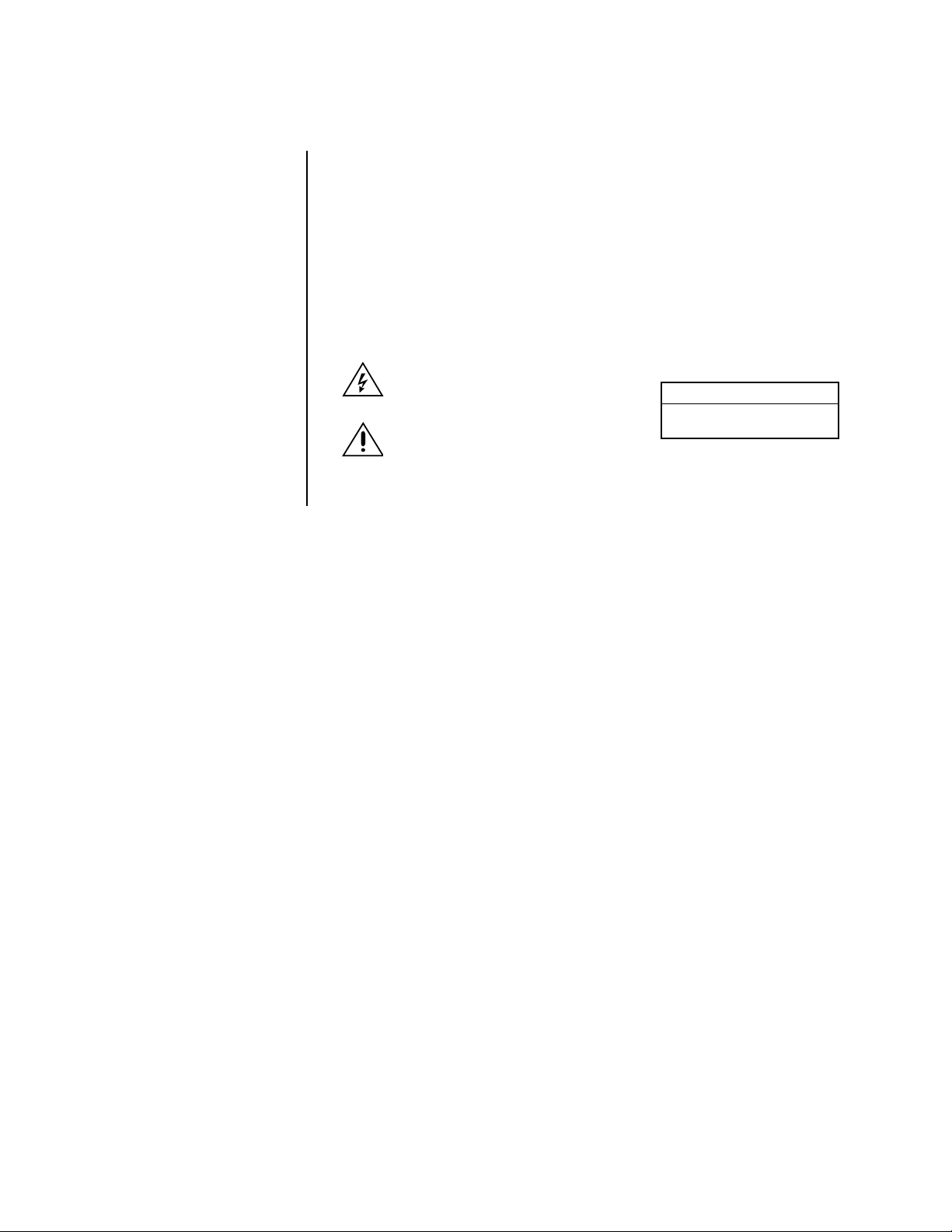
FRONT PANEL CONTROLS
2 3
1
TIMER REC
POWER
TIMER REC M-DET PRE ALARM REC
ACCESS LOCK
8
SPLIT/SEQUENCE
321465
ZOOM
0
INFO
9
CAMERA
SET UP
4
SEARCH
COPY
MENU
56 7
CLEAR/
REC
ARCHIVE
MAIN
ARCHIVE
COPY
REW
STOP
PAUSE
REV PLAY
SHUTTLE
HOLD
987
PLAY DEVICE
WARNING
EJECT
RESET
111213 1415 16 17
10
ENTER/
FF
PLAY
-+
PLAY MODE
Figure 1. Front Panel Controls, DX3009 Models
4
SPLIT/SEQUENCE
ZOOM
0
TIMER RECPOWER
12
321
46591011 12 13 14 15 1687
TIMER REC M-DET PRE ALARM REC
ACCESS LOCK
REMOTE CONNECT RECEIVE SEND
18
8
Figure 2. Front Panel Controls, DX3016 Models
1. POWER button
Press this button to turn the power on; press again to turn the power off. This button
lights/goes off when the power is on/off. It flashes when switching between functions,
such as during setup. When the POWER button is flashing, the front panel buttons do
not work.
2. TIMER REC button
Press this button to activate the timer recording function. Press again to cancel the
timer recording function. The light is on when timer recording is in progress.
CAMERA
SEARCH
COPY
SET UP
INFO
MENU
3
9
WARNING
RESET
10
6
5
CLEAR/
REW
REC
ARCHIVE
STOP
PAUSE
SHUTTLE
HOLD
REV PLAY
PLAY DEVICE
EJECT
MAIN
ARCHIVE
COPY
11 12 13 1415 16 17
7
ENTER/
PLAY
-+
PLAY MODE
00508
FF
Pelco Manual C681M-D (2/02) 7
Page 9

3. Recording indicators
TIMER REC indicator
This light illuminates during timer recording and timer recording standby mode.
The POWER button does not work when the TIMER REC indicator is lit. To turn on the
power when the TIMER REC indicator is lit in the standby mode, press the TIMER
REC button.
M-DET indicator
The light illuminates whenever the motion detection setting is ON in the Initial Set Up
menu. When the setting is ON, the light goes out if you are in a programming menu.
PRE ALARM REC indicator
The light illuminates whenever SHORT, MEDIUM, or LONG is selected in the pre-alarm
recording (PRE A-REC) field in the alarm recording and motion detection (A-Rec/M-Det
Setting) menu.
4. Multiplexer buttons
Camera number buttons
Buttons 1-9 on DX3009 models
Buttons 1-16 on DX3016 models
Press the number of the camera you want to display on the monitor. In addition, these
buttons are used to set the password in the Password Lock function.
SPLIT/SEQUENCE button
Press this button to switch between the single-camera, four-camera, and nine-camera
displays on DX3009 models and between single-camera, four-camera, nine-camera,
and sixteen-camera displays on DX3016 models. Also use to switch sequence functions.
ZOOM button
Press this button to display the Zoom Pointer (X) on the monitor. In addition, this button can be used as the number 0 to set the password in the Password Lock function.
ZOOM IN button
Button 4 on DX3009 models
Button 1 on DX3016 models
Pressing this button after pressing the ZOOM button enlarges the image in two steps.
ZOOM OUT button
Button 5 on DX3009 models
Button 2 on DX3016 models
Pressing this button after pressing the ZOOM IN button reduces the image.
Move buttons
Buttons 6-9 on DX3009 models
Buttons 3-6 on DX3016 models
Press these buttons to move the Zoom Pointer to the desired position.
5. REC button
Press this button to begin recording.
6. ARCHIVE button
Press this button to begin making a backup copy of the hard drive. If there is no peripheral recording device connected, this button cannot be used.
7. Jog and shuttle operation
SHUTTLE ring
Use the ring to set various menus and search functions, to adjust the playback speed,
and to rewind or forward the image.
JOG dial
Use the dial to set various menus and search functions, and to forward or reverse the
image during playback (field-by-field).
8 Pelco Manual C681M-D (2/02)
Page 10

8. Mode indicators
ACCESS indicator
This light flashes when the hard disk drive or peripheral recording devices are being
accessed.
LOCK indicator
This light illuminates when the LOCK button is set to ON.
9. Menu buttons
Press one of the buttons to display each menu. Press again to exit the menu.
INFO button
Press this button to display the Information menu.
SET UP button
Press this button to display the Menu Setting menu.
COPY button
Press this button to display the Copy Selection menu. This button works only if a peripheral device is connected to SCSI ID 4 and SCSI ID 5.
SEARCH button
Press this button to display the Search Selection menu.
COPY indicator
This indicator blinks during a copy or restore operation and illuminates during copying.
10. WARNING RESET button
Press this button to clear a warning displayed on the monitor.
This button also clears the “X” that appears on the monitor after a power failure.
11. PLAY DEVICE button
Press this button to select a playback device. If there is no peripheral recording device
connected, this button cannot be selected.
EJECT button
Press this button to eject the medium in the playback device. If there is no peripheral
recording device connected, this button cannot be used.
12. Play device indicators
The illuminated light indicates the device selected by the PLAY DEVICE button.
13. STOP button
Press this button to stop recording or playback. To stop a timer recording, press the
TIMER REC button.
14. PAUSE button
When pressed during recording, the recording pauses. Press again to resume recording. When pressed during playback, a still picture is displayed.
SHUTTLE HOLD button
This button retains the selected playback or reverse playback speed.
15. REV PLA Y button
Press this button to begin reverse playback.
16. PLAY MODE buttons
These buttons switch the playback interval while in still mode and playback.
17. PLAY button
Press this button to begin playback.
Pelco Manual C681M-D (2/02) 9
Page 11
18. REMOTE communication button and indicator lights
(DX3016 Models Only)
Not used.
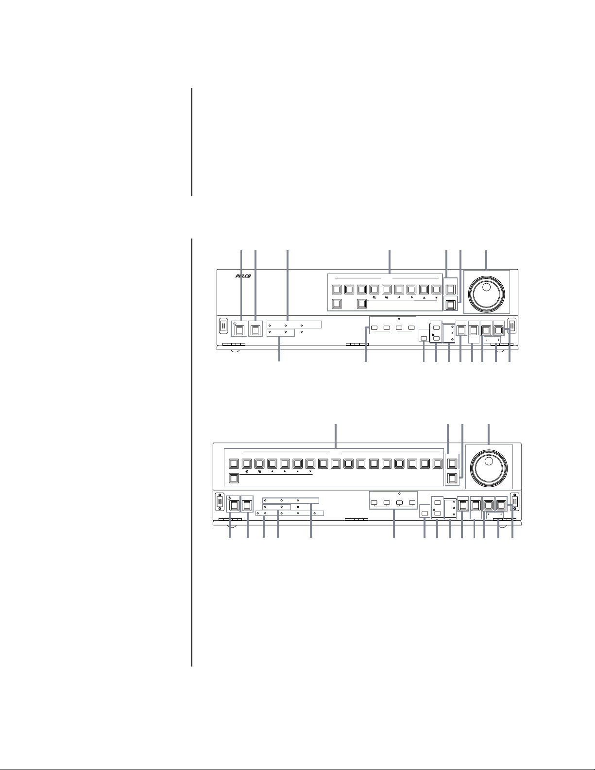
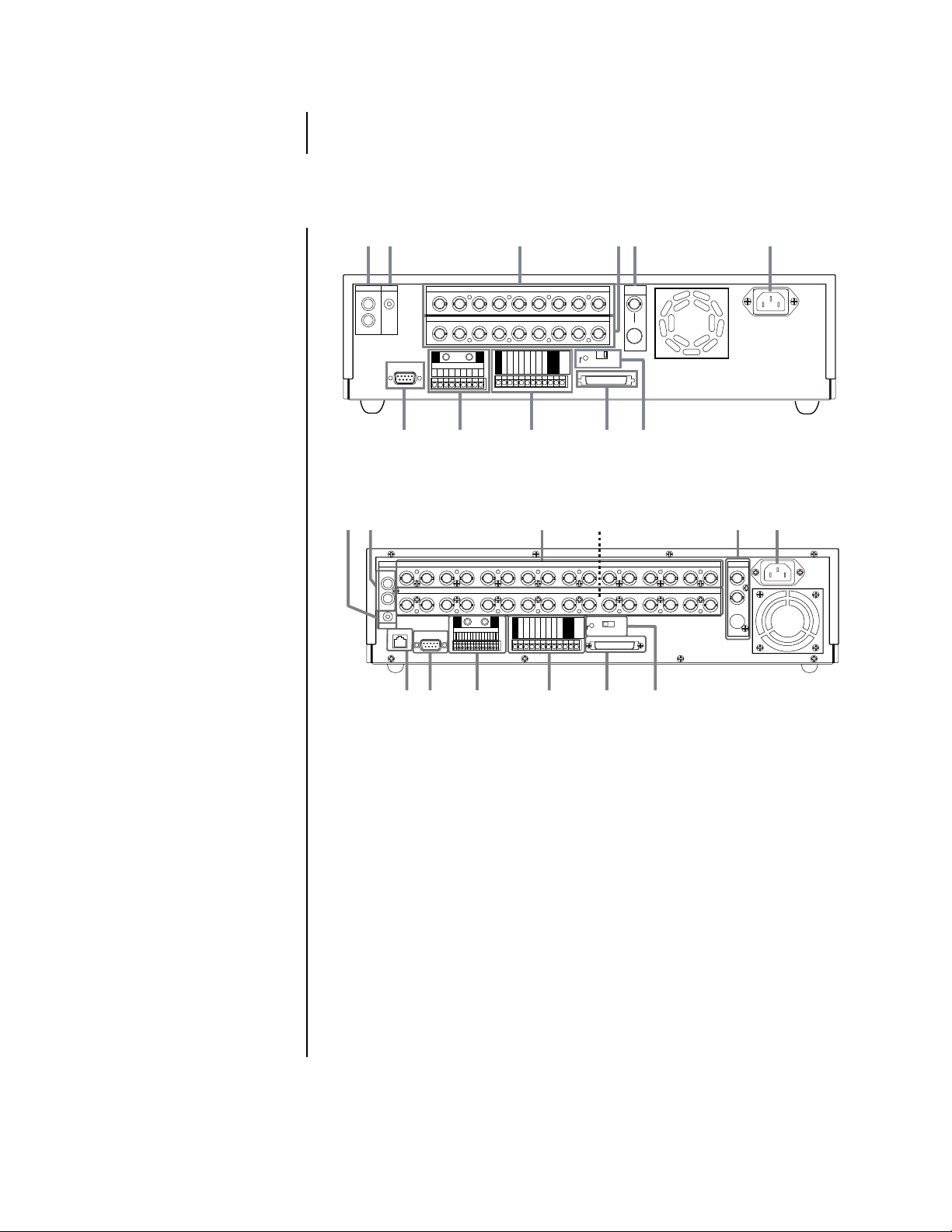
REAR PANEL CONNECTORS
1
AUDIO
OUT
2
MIC
IN
RS-232C
7
1
23456789
234
1
GND
ALARM IN
1
23456789
8
3
CAMERA IN
CAMERA OUT
56789
GND
GND
CLOCK ADJ
REC
POWER ON
POWER OFF
ALARM OUT
MODE OUT
9
GND
CALL OUT
CALL OUT GND
GND
DC 5V OUT
RESET
MAX 30mA
4
ON OFF
SCSI
TERMINATION
SCSI
10 11
5
VIDEO
OUT
Y/C
6
Figure 3. Rear Panel Connectors, DX3009 Models
1
2
AUDIO
1234 5678910111213141516
IN
1234 5678910111213141516
OUT
MIC
ETHERNET
RS-232C
ALARM IN
987654321
3
CAMERA IN
CAMERA OUT
GNDGND
16151413121110
CLOCK ADJ
REC
POWER ON
POWER OFF
ALARM OUT
GND
MODE OUT
CALL OUT
CALL OUT GND
GND
GND
DC 5V OUT
RESET
MAX 30mA
4
ON OFF
SCSI
TERMINATION
SCSI
5
VIDEO OUT
Y/C
6
78
12
9
10
11
Figure 4. Rear Panel Connector, DX3016 Models
1. Audio connectors
AUDIO IN connector
This is an RCA input connector for an audio signal.
AUDIO OUT connector
This is an RCA output connector for an audio signal.
2. MIC jack
This is an input connector for a microphone (600-ohm impedance).
3. CAMERA IN connectors
These are BNC input connectors for cameras.
4. CAMERA OUT connectors
These are BNC output (looping) connectors for cameras.
5. VIDEO OUT connectors
There are two video output connectors: a BNC standard composite video output connector and an SVHS connector for separate luminance and chrominance (Y/C) signals.
Both connectors can be used at the same time.
00510
10 Pelco Manual C681M-D (2/02)
Page 12

6. AC power socket
This socket is for a 100-240 VAC power cord.
7. RS-232C connector
This is where a PelcoNet™ Transmission System can be connected for remote viewing and control of cameras.
8. ALARM IN terminals
These are input terminals for alarm signals.
GND terminals
These are earth ground terminals for the ALARM IN terminals. Use only the terminal
screws provided with this unit; otherwise, the recorder could be damaged or connections may be poor.
9. I/O terminals
GND terminals
These are ground terminals for the input/output terminals.
CLOCK ADJ terminal
This is an input terminal to set the time display. The time display is adjusted to the
nearest hour (00 minutes, 00 seconds) when this terminal receives the clock adjust
signal.
REC terminal
This is an input terminal to start recording.
POWER ON terminal
This is an input terminal to turn on the recorder through a peripheral device.
POWER OFF terminal
This is an input terminal to turn off the recorder through a peripheral device.
ALARM OUT terminal
This is an output terminal to indicate that an alarm recording is being made.
MODE OUT terminal
This is an output terminal to indicate the recorder’s current mode. Select the mode in
the Rear Terminal menu.
CALL OUT terminal / CALL OUT GND terminal
This is an isolated (optically coupled) output to indicate information such as the hard
disk drive is full. Refer to the
DC 5V OUT terminal
This terminal is for direct current voltage output. The maximum current is 30 mA.
10. SCSI connector
This connector is for peripheral recording devices.
11. RESET button
When pressed, the present time is erased, the system is reset, and the power is
turned off.
SCSI TERMINATION switch
When set to ON, the termination function is enabled; when set to OFF, the termination
function is disabled. Set the switch ON when nothing is connected to the SCSI connector.
12. Ethernet connector (DX3016 Models Only)
Not used.
Warnings
section.
Pelco Manual C681M-D (2/02) 11
Page 13
INSTALLATION
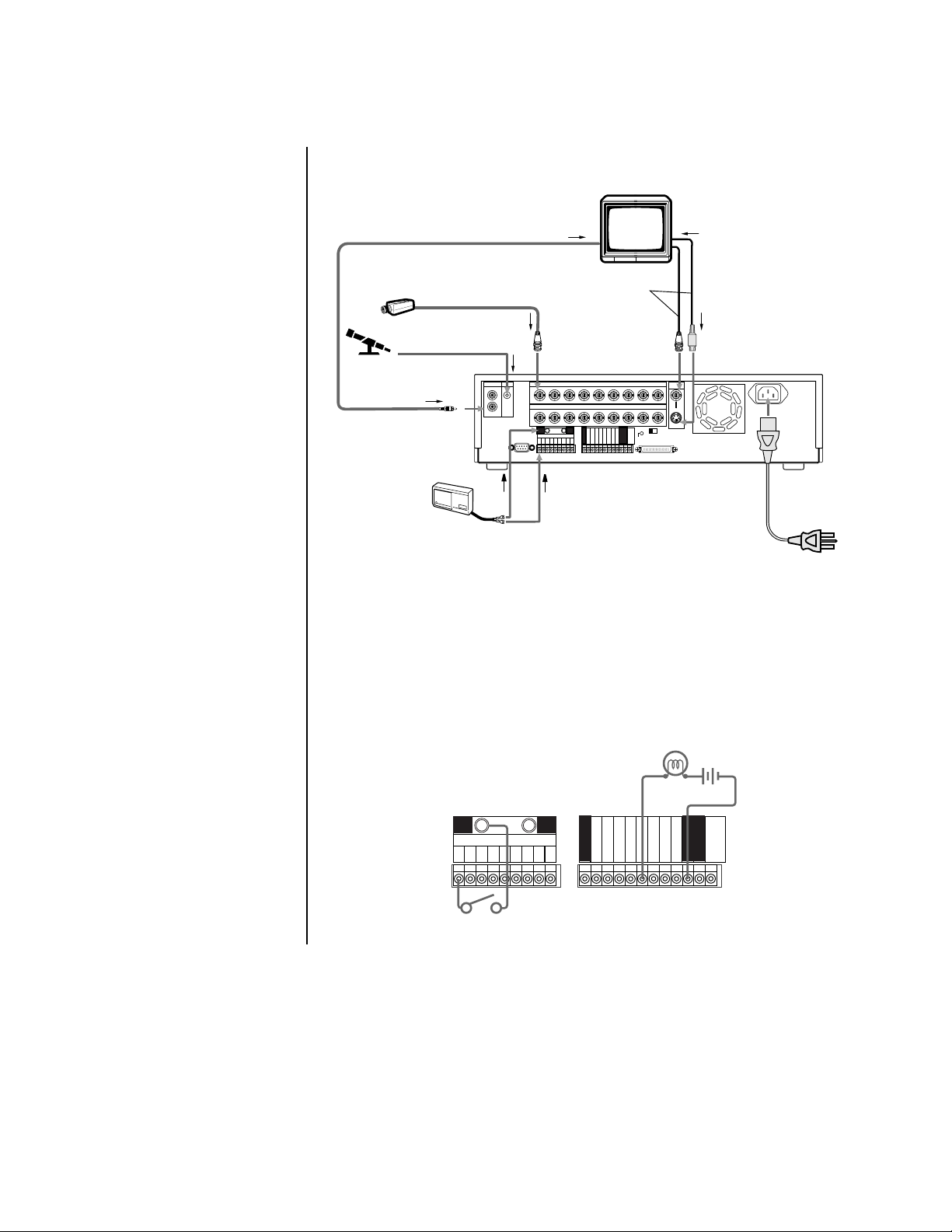
1. Connect cameras, monitor, and audio equipment to the recorder as shown in Figure 5.
MICROPHONE
To AUDIO OUT terminal
CAMERA #1
To peripheral loudspeaker or monitor
through AUDIO IN terminal
Up to 9 cameras
To CAMERA IN 1
terminal
To M IC terminal
MIC
IN
OUT
Either cable can
•••
1
23456789
1
234
GND GND
ALARM IN
RS-232C
123456789
MONITOR
be connected.
VIDEO OUT
S(Y/C) OUT
CAMERA INAUDIO
CAMERA OUT
5678
CLOCK ADJ
REC
POWER ON
POWER OFF
ALARM OUT
MODE OUT
CALL OUT
CALL OUT GND
GND
GND
To
or
terminal
RESET
DC 5V OUT
MAX 30mA
GND
ON OFF
SCSI
TERMINATION
SCSI
9
To S (Y/C) IN
terminal
VIDEO
OUT
Y/C
To ALARM IN terminal
corresponding to the
CAMERA #
SENSOR #1
•
•
•
To GND
terminal
POWER CORD
Figure 5. Equipment Connections (DX3009 Model Shown)
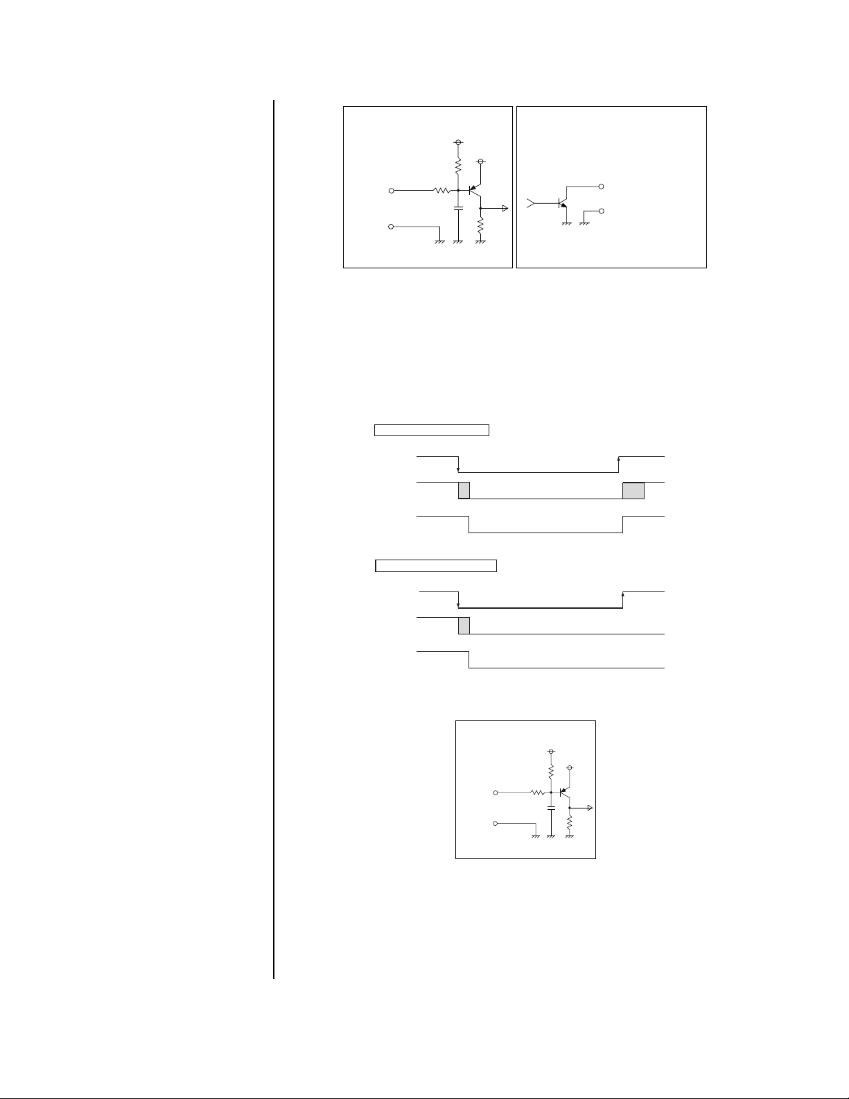
2. Connect alarm inputs and alarm output as shown in Figures 5 and 6. Figure 7 shows
schematics for the alarm circuits.
An alarm input is active when a ground or low voltage signal is applied. An input is
non-active when the terminal is open.
The alarm output is active when the terminal is at a low voltage level and non-active
when the terminal is open. Maximum drive current is 7 mA DC, and the maximum voltage is +24 VDC.
peripheral alarm lamp
or buzzer
GND GND
ALARM IN
123456789
alarm switch
CLOCK ADJ
REC
GND
POWER ON
POWER OFF
ALARM OUT
MODE OUT
CALL OUT
CALL OUT GND
GND
GND
DC 5V OUT
MAX 30mA
Figure 6. Alarm Input and Output Connections
12 Pelco Manual C681M-D (2/02)
Page 14
POWER ON/POWER OFF/
Using POWER ON terminal
POWER ON
terminal
ground
0V
power off
Unit's
power
DC 5V OUT
(4.5-5.5V
Max.30mA)
DC 5V
power on
power on
shut down
boot
up
Using POWER OFF terminal
POWER OFF
terminal
0V
power off
ground
shut down
power on
Unit's
power
DC 5V OUT
(4.5-5.5V
Max.30mA)
DC 5V
ALARM IN/REC/CLOCK ADJ
Input terminal
• Input Circuit
Input
terminal
GND
<Interface circuit inside the unit>
0.047µF
5V
10kΩ
22kΩ
ALARM OUT/MODE OUT Output terminal
• Output Circuit
5V
Output terminal
GND terminal
<Interface circuit inside the unit>
Figure 7. Schematics for Alarm Input and Output Terminals
3. Optional. Connect the recorder to a remote source for turning the unit on/off.
By using the POWER ON/POWER OFF terminals, it is possible to turn on/off the
recorder externally. The POWER ON terminal turns power on or off (refer to Figure 8).
The POWER OFF terminal turns power off (refer to Figure 8). Turning the recorder on/off
also controls the output of the DC 5V OUT terminal (refer to Figure 8). Figure 9 shows
the schematic for the POWER ON/POWER OFF terminals.
Figure 8. Operation of Power On and Power Off Terminals
POWER ON/POWER OFF/
ALARM IN/REC/CLOCK ADJ
Input terminal
• Input Circuit
Input
terminal
<Interface circuit inside the unit>
GND
0.047µF
10kΩ
22kΩ
5V
5V
Figure 9. Schematic for Power On and Power Off Terminals
Pelco Manual C681M-D (2/02) 13
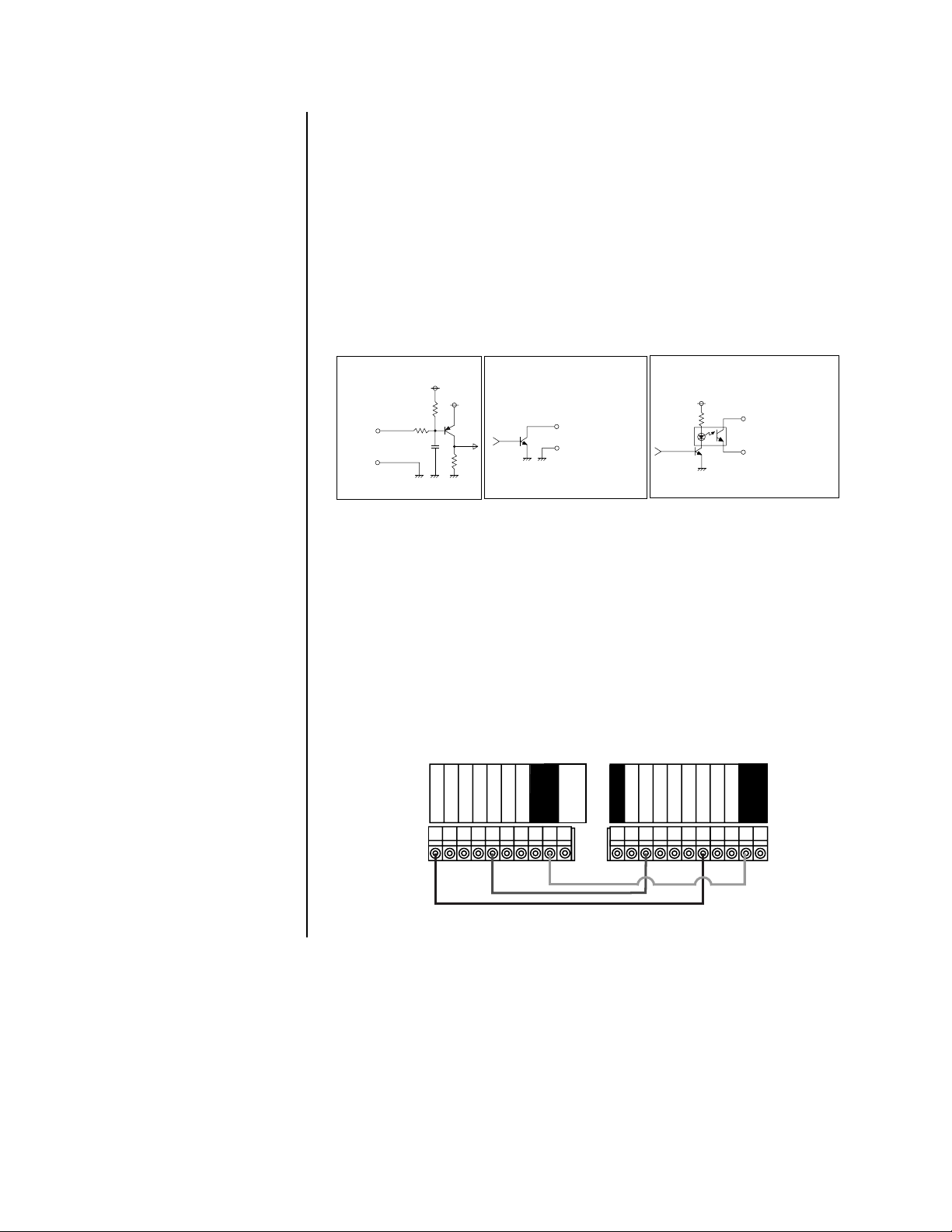
4. Optional. Connect equipment to the CLOCK ADJ, REC, MODE OUT, and CALL OUT
terminals. Refer to Figure 10 for schematics of the input/output terminals.
The CLOCK ADJ input terminal is used for adjusting the clock. The input is active
when a ground or low voltage signal is applied. The input is non-active when the terminal is open.
Page 15
The REC input terminal is used to start recording. Refer to
Series Recording
in this step for
more information. The input is active when a ground or low voltage signal is applied. The input is non-active when the terminal is open.
The MODE OUT output terminal is used to indicate the status of the recorder (refer to
Out
in the
other recorder (refer to
Programming
section for more information). It can also be used to turn on an-
Series Recording
in this step for more information). The output is
Mode
active when the terminal is at a low voltage level and non-active when the terminal is open.
Maximum current drive is 7 mA DC, and the maximum voltage is +24 VDC.
The CALL OUT output terminal is used for warnings (refer to the
information). It can also be used to turn on another recorder (refer to
Warnings
section for more
Series Recording
in
this step for more information). The output is active when the optical coupler is turned on
and non-active when the optical coupler is turned off. Maximum current drive is 7 mA DC,
and the maximum voltage is +24 VDC.
POWER ON/POWER OFF/
ALARM IN/REC/CLOCK ADJ
Input terminal
• Input Circuit
Input
terminal
<Interface circuit inside the unit>
GND
0.047µF
5V
10kΩ
22kΩ
ALARM OUT/MODE OUT Output terminal
• Output Circuit
5V
Output terminal
GND terminal
<Interface circuit inside the unit>
CALL OUT output terminal
• Output Circuit
CALL OUT terminal
CALL OUT GND terminal
<Interface circuit inside the unit>
Figure 10. Schematics for Input and Output Terminals
SERIES RECORDING
By connecting multiple units in series as shown in Figure 11, when the one unit’s hard disk
is full, the next unit automatically begins recording.
In this example, when the first unit’s hard disk is full, the second unit begins recording;
when the second unit’s hard disk is full, the first unit begins overwriting its hard disk. If you
do not want the first unit to overwrite its hard disk, do not connect MODE OUT from the
second unit to REC of the first unit. The series recording function can also be activated by
connecting the CALL OUT terminal in place of the MODE OUT terminal; the disk storage
capacity setting is made in the Call Out menu. When the CALL OUT terminal is used, if the
first unit reaches the preset capacity, experiences a malfunction, or otherwise cannot continue recording, the second unit begins recording.
REC
POWER OFF
POWER ON
First Unit
MODE-OUT
ALARM-OUT
CALL OUT GND
CALL OUT
GND
GND
DC 5V OUT
MAX 30mA
Second Unit
CLOCK ADJUST
REC
POWER ON
GND
POWER OFF
ALARM OUT
MODE OUT
CALL OUT
CALL OUT GND
GND
GND
Figure 11. Connecting Recorders in Series
14 Pelco Manual C681M-D (2/02)
Page 16
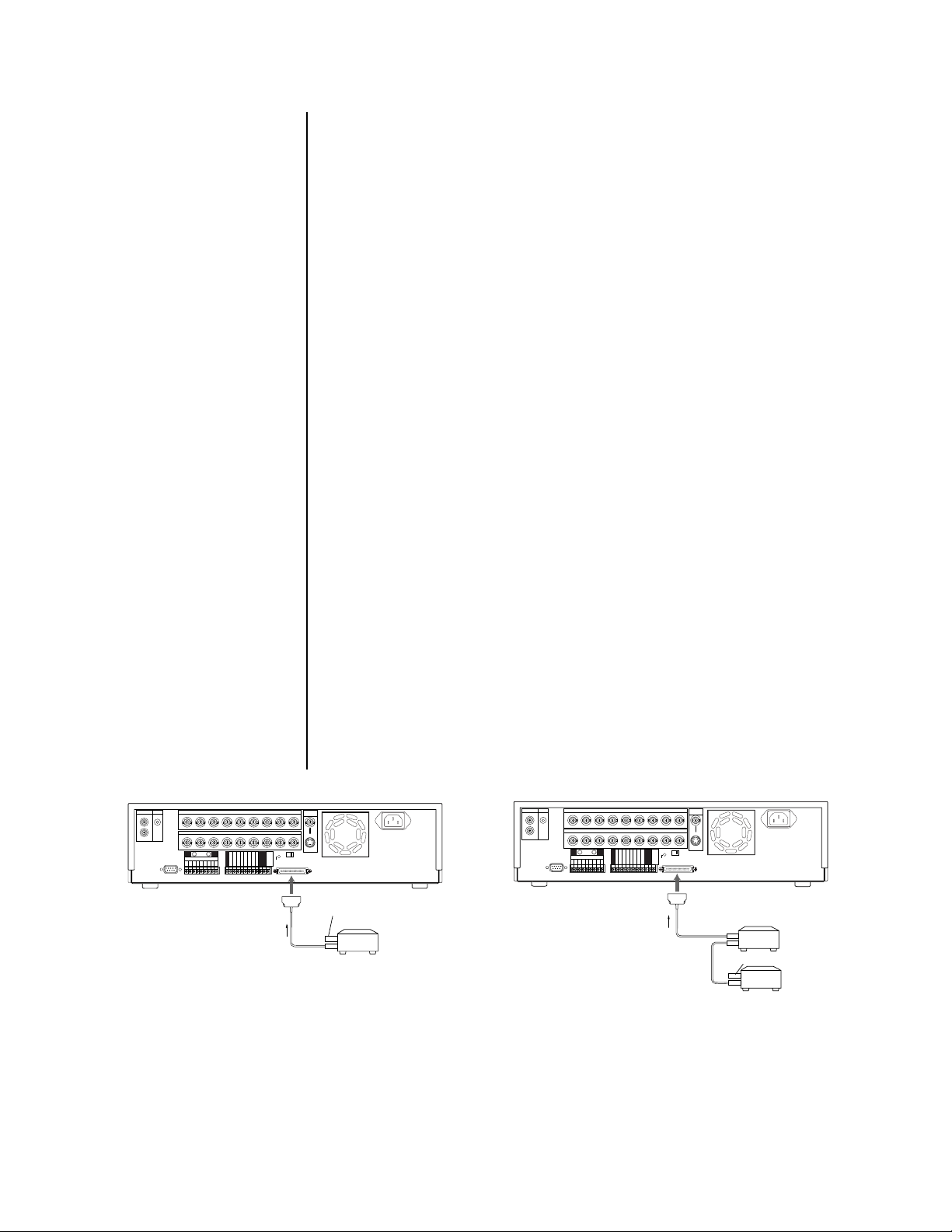
5. Optional. Connect peripheral recording devices.
By connecting peripheral recording devices to the recorder through the SCSI interface
(SCSI-II half-pitch 50-pin), storage space can be increased and archiving and copying
functions can be performed.
To increase storage space, up to two (DX3009-060, DX3016-060, and DX3016-120)
or three (DX3009-030) peripheral hard disk drives (maximum of 34 GB per unit for
DX3009 models or 103 GB per unit for DX3016 models) can be added to supplement
the built-in hard disk.
For archiving or copying functions, a tape or disk device can be connected.
The following tape devices can be connected to the recorder:
Pelco DX3000-D25 (drive)
Pelco DX3000-T25 (blank tape)
The following disk devices can be connected to the recorder:
MO (640 MB) Fujitsu SMB-640WF
MO (1.3 GB) Fujitsu SMB-1300W
DVD-RAM Panasonic LF-D200JD
HDD SCSI-IF Type
Zip (250 MB) IOMEGA Z250S
Connections between the recorder and peripheral devices are made with SCSI cables
(not supplied). As SCSI cables differ with each device, check for the appropriate pin
arrangement before use. Cables must not exceed 3 feet (1 m).
On the rear panel of the recorder is a SCSI termination switch. Set the switch ON
when nothing is connected the SCSI connector. Set to OFF when connecting peripheral devices.
Correct termination is necessary to maintain proper electrical connections to the peripheral devices. Make sure that the last peripheral device is terminated. (Depending
on the device, the terminator may be built into the device. In this case, set the built-in
terminator correctly.) Use an active terminator for SCSI.
Set the SCSI ID number of the peripheral recording device. Refer to the operation
manual of each peripheral recording device for setting the SCSI ID Number. Use ID1-3
for hard drives, ID4 for an archive device, and ID5 for a copy device. On DX3016 models, also use ID4 when a hard disk drive is connected for repeated backup recording
(considered an archiving function).
MIC
MIC
AUDIO
IN
OUT
RS-232C
CAMERA IN
123456789
CAMERA OUT
1234
GND GND
123456789
ALARM IN
56789
CLOCK ADJ
REC
POWER ON
POWER OFF
ALARM OUT
MODE OUT
CALL OUT
CALL OUT GND
DC 5V OUT
GND
GND
GND
SCSI
terminal
RESET
MAX 30mA
ON OFF
SCSI
TERMINATION
SCSI
SCSI cable
VIDEO
OUT
Y/C
Terminator
Peripheral
copy/archive
device
01147
AUDIO
IN
OUT
RS-232C
CAMERA IN
123456789
CAMERA OUT
1234
GND GND
123456789
ALARM IN
56789
CLOCK ADJ
REC
POWER ON
POWER OFF
ALARM OUT
MODE OUT
CALL OUT
CALL OUT GND
DC 5V OUT
MAX 30mA
GND
GND
GND
SCSI
terminal
ON OFF
SCSI
TERMINATION
RESET
SCSI
SCSI cable
VIDEO
OUT
Y/C
SCSI cable
SCSI cable
Peripheral
hard disk
drives
Terminator
011487
Figure 12. Connecting Peripheral Recording Devices (DX3009 Models Shown)
Pelco Manual C681M-D (2/02) 15
Page 17
6. Connect the power cord to the recorder, and then plug the power cord into a wall
socket.
7. Turn on power to peripheral recording devices first, and then turn on the power to the
recorder. Power to the cameras and monitor can be turned on before or after turning
on the recorder.
If there are no peripheral devices connected to the SCSI terminal, the installation is
complete. Proceed to the
Programming
section.
If there are peripheral devices connected to the SCSI terminal, the recorder automatically detects peripheral recording devices connected to the SCSI terminal.
<DEVICE CHECK>
SCSI ID0:HDD (30GB)
ID1:HDD ( 9GB)
ID2:NONE
ID3:NONE
ID4:NONE
ID5:NONE
PWR-OFF INITIALIZE
BOOT UP DELAY 00
If a hard drive(s) has been added, refer to the
Adding a Hard Drive(s)
information about turning on the recorder.
If a peripheral device takes a long time to start up, refer to the section on
ADDING OR REMOVING A COPY OR ARCHIVE DEVICE
1. Turn off the power.
2. Connect or disconnect the copy or archive device.
3. Turn on the power.
ADDING A HARD DRIVE(S)
This section applies only to devices connected to ID1-ID3.
WARNING:
additional hard drive(s) and turn the power back on. Back up data you want
to save before turning off the power to add a hard drive(s).
NOTE:
The DX3000 uses the native format of the added drive(s); therefore, any
added drive(s) do not have to be reformatted.
Up to two (DX3009-060) or three (DX3009-030) peripheral hard disk drives (maximum of 34 GB
per unit) can be added to supplement the built-in hard disk when extended recording time is
needed.
1. If a hard drive(s) has been added, a screen similar to the first one on the left appears
after turning on the power. This screen shows a peripheral device connected to ID1.
If the second screen to the left appears, it is possible that there is either a poor con-
nection, overlapping SCSI ID numbers, or an error in SCSI ID number settings. In this
case, turn the SHUTTLE ring twice in the clockwise direction. Main power to the recorder is turned off. Check the connection and SCSI ID settings.
All data will be lost on the current drive(s) after you install an
section for more
Boot-Up Delay.
2. Make sure that the connected device(s) is recognized correctly.
ID4:RDD
ID5:DDS
PWR-OFF
BOOT UP DELAY 00
If the connected device(s) is not displayed correctly, make sure that the cursor is beside POWER OFF. If the cursor is not beside POWER OFF, turn the JOG dial to move
the cursor beside POWER OFF, and then turn the SHUTTLE ring twice to the right.
The recorder’s power is turned off. Make sure that the connection of the external device
and the setting of the SCSI ID number is correct, and then turn the power back on.
3. Turn the JOG dial to select INITIALIZE.
4. Turn the SHUTTLE ring to the right when “Turn the SHUTTLE RING >> to EX-
ECUTE.” is displayed.
16 Pelco Manual C681M-D (2/02)
Page 18

ID5:RDD
PWR-OFF CONFIG.
BOOT UP DELAY 00
<DEVICE CHECK>
SCSI ID0:HDD (30GB)
ID1:HDD ( 9GB)
ID2:NONE
ID3:NONE
ID4:NONE
ID5:NONE
INITIALIZE ALL HDD
BOOT UP DELAY 00
REMOVING A HARD DRIVE(S)
This section applies only to devices removed from ID1-ID3.
1. Turn off power.
2. Remove the hard drive(s).
3. Turn on power. The screen to the left appears.
4. Make sure that any connected device is recognized correctly.
5. Turn the JOG dial to select CONFIG., and then turn the SHUTTLE ring to the right
twice. The recorder starts configuring.
When CONFIG. is selected, the recorder saves the data recorded on any connected
peripheral recording device (which has not been removed) as well as the data recorded on the built-in hard drive. Data recorded on a removed peripheral recording device is not affected.
CONFIRMING THAT A DEVICE IS CONNECTED
1. Press the INFO button. The Information menu appears.
2. Turn the JOG dial to move the cursor beside CONNECTED SCSI DEVICE.
3. Turn the SHUTTLE ring to the right. The Connected SCSI Device menu appears.
4. Press the INFO button to exit.
BOOT-UP DELAY
Because the recorder searches for connected devices when power is turned on, peripheral
devices must be turned on before power is turned on to the digital recorder. To handle peripherals that take a long time to start up, the recorder can be preset to delay the timing of
its search for these devices, as follows.
1. Press the POWER button while pressing the REC button to turn the power on. The
Device Check menu appears.
2. Turn the JOG dial to move the cursor beside BOOT UP DELAY, and then turn the
SHUTTLE ring to the right. The boot-up delay option starts flashing.
3. Turn the JOG dial to set the delay time, and then turn the SHUTTLE ring to the right.
You can set the time from 00 to 99 seconds.
NOTE:
When the boot-up delay is set and a timer recording is performed, the
recorder will begin recording later than the time set as the recording time.
4. Press the POWER button. The recorder’s power is turned off.
5. Press the POWER button again. The recorder starts configuring after the preset de-
layed time has passed.
If a different peripheral recording device was connected since the last time the re-
corder was booted up, the Device Check menu appears.
Pelco Manual C681M-D (2/02) 17
Page 19
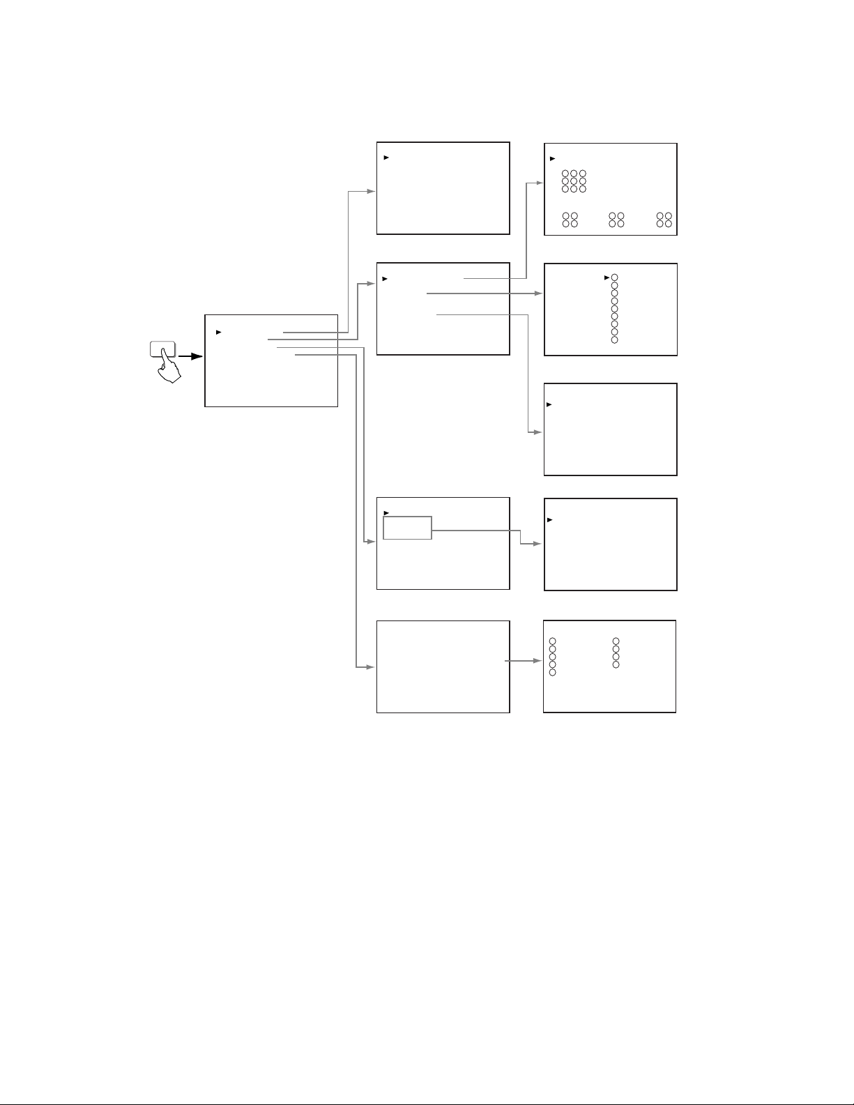
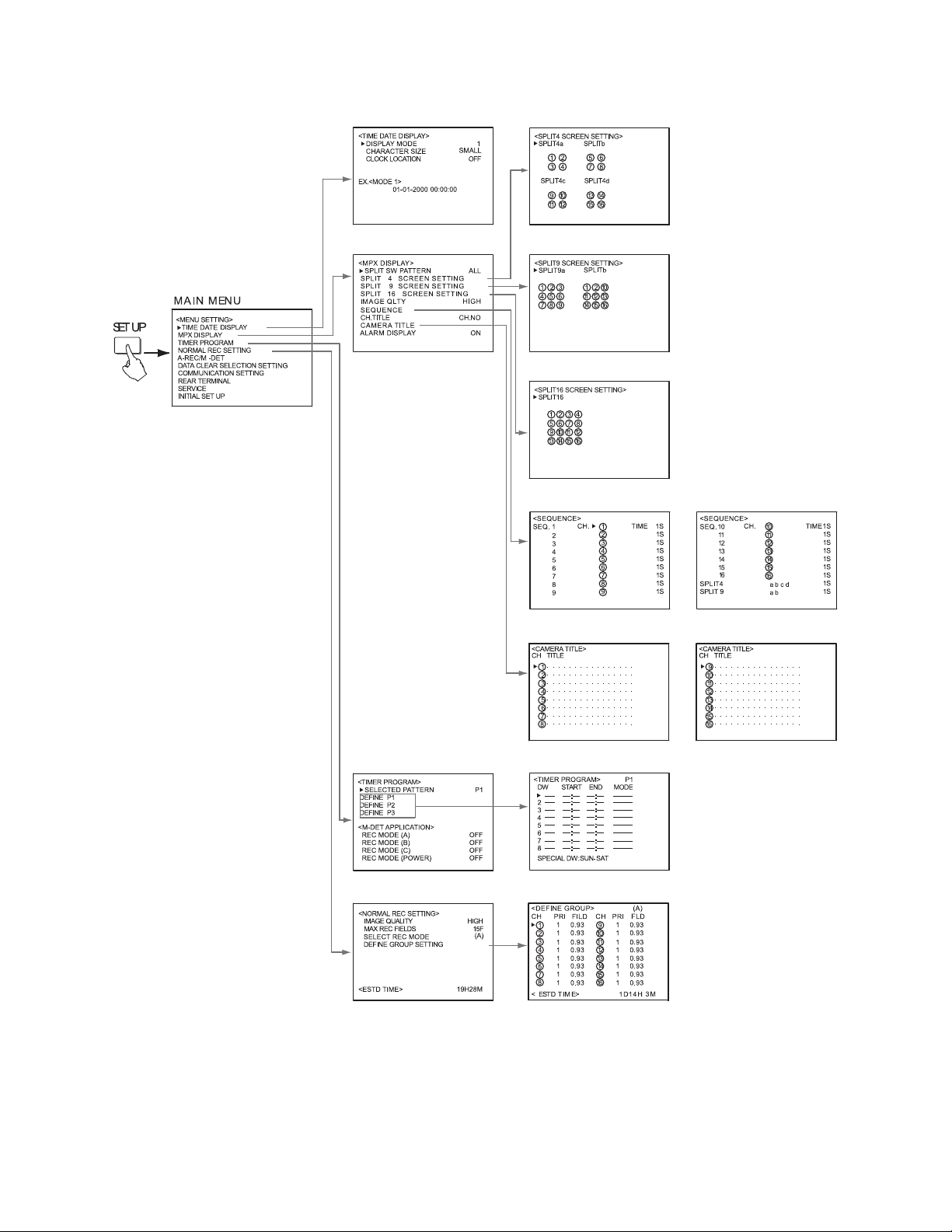
PROGRAMMING
SUB MENU (1) SUB MENU (2)
<TIME DATE DISPLAY>
DISPLAY MODE 1
CHARACTER SIZE SMALL
CLOCK LOCATION OFF
EX.<MODE 1>
01-01-2000 00:00:00
<SPLIT SCREEN SETTING>
SPLIT9
1 2 3
4 5 6
7 8 9
SPLIT4A
1 2
3 4
SPLIT4B
5 6
7 8
SPLIT4C
1 2
3 9
SET UP
MAIN MENU
<MENU SETTING>
TIME DATE DISPLAY
MPX DISPLAY
TIMER PROGRAM
NORMAL REC SETTING
A-REC/M-DET SETTING
DATA CLEAR SELECTION
COMMUNICATION SETTING
REAR TERMINAL
SERVICE
INITIAL SET UP
<MPX DISPLAY>
SPLIT SCREEN SETTING
IMAGE QLTY HIGH
SEQUENCE
CH.TITLE CH.NO
ALARM DISPLAY ON
CAMERA TITLE
<TIMER PROGRAM>
SELECTED PATTERN P1
DEFINE P1
DEFINE P2
DEFINE P3
<NORMAL REC SETTING>
IMAGE QUALITY HIGH
MAX REC FIELDS 15F
SELECT REC MODE (A)
DEFINE GROUP SETTING
<SEQUENCE>
SEQ. 1
2
3
4
5
6
7
8
9
SPLIT4
<CAMERA TITLE>
CH TITLE
1
2
3
4
5
6
7
8
9
<TIMER PROGRAM> P1
DW START END MODE
––– ––:–– ––:–– ––––––
2 ––– ––:–– ––:–– ––––––
3 ––– ––:–– ––:–– ––––––
4 ––– ––:–– ––:–– ––––––
5 ––– ––:–– ––:–– ––––––
6 ––– ––:–– ––:–– ––––––
7 ––– ––:–– ––:–– ––––––
8 ––– ––:–– ––:–– ––––––
SPECIAL DW:SUN–SAT
<DEFINE GROUP> (A)
CH PRI FILD CH PRI FILD
1 1 1.66 6 1 1.66
2 1 1.66 7 1 1.66
3 1 1.66 8 1 1.66
4 1 1.66 9 1 1.66
5 1 1.66
CH. TIME 1S
1
2
3
4
5
6
7
8
9
abc
...............
...............
...............
...............
...............
...............
...............
...............
...............
1S
1S
1S
1S
1S
1S
1S
1S
1S
.
.
.
.
.
.
.
.
.
<ESTD TIME> 19H28M
<ESTD TIME> 19H28M
Figure 13. Menu Tree, DX3009 Models
18 Pelco Manual C681M-D (2/02)
Page 20
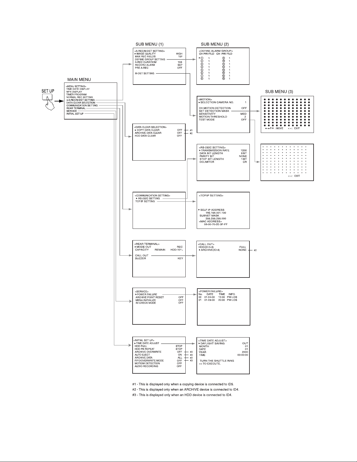
SET UP
MAIN MENU
<MENU SETTING>
TIME DATE DISPLAY
MPX DISPLAY
TIMER PROGRAM
NORMAL REC SETTING
A-REC/M-DET SETTING
DATA CLEAR SELECTION
COMMUNICATION SETTING
REAR TERMINAL
SERVICE
INITIAL SET UP
SUB MENU (1)
<A-REC/M-DET SETTING>
IMAGE QUALITY HIGH
MAX REC FIELDS 15F
DEFINE GROUP SETTING
A-REC DURATIOM 1M
RECORD ALARM SEP
PRE A-REC OFF
M-DET SETTING
SUB MENU (2)
<DEFINE ALARM GROUP>
CH PRI FILD CH PRI FILD
1 1 6 1
2 1 7 1
3 1 8 1
4 1 9 1
5 1
<MOTION>
SELECTION CAMERA NO. 1
CH.MOTION DETECTION OFF
SET DETECTION MASK
SENSITIVITY MED
MOTION THRESHOLD 2
TEST MODE OFF
SUB MENU (3)
: MOVE < < : EXIT
<DATA CLEAR SELECTION>
COPY DATA CLEAR OFF
ARCHIVE DATA CLEAR OFF
HDD DATA CLEAR OFF
<COMMUNICATION SETTING>
RS-232C SETTING
<REAR TERMINAL>
MODE OUT REC
CAPACITY REMAIN HDD-10%
CALL OUT
BUZZER KEY
<SERVICE>
POWER FAILURE
ARCHIVE POINT RESET OFF
MENU INITIALIZE OFF
IM - CHECK MODE OFF
#1
#2
<RS-232C SETTING>
TRANSMISSION RATE 1200
DATA BIT LENGTH 8BIT
PARITY BIT NONE
STOP BIT LENGTH 1BIT
DELIMITER CR
<CALL OUT>
HDD(ID:0-3) FULL
ARCHIVE(ID:4) NONE
<POWER FAILURE>
No. DATE TIME INFO.
01 01-23-00 20:00 PW-LOS
02 01-24-00 12:00 PW-LOS
< < : EXIT
#2
<INITIAL SET UP>
TIME DATE ADJUST
HDD FULL STOP
HDD PB REPEAT STOP
ARCHIVE OVERWRITE OFF
AUTO EJECT ON
ARCHIVE DATA ALL
MOTION DETECTION OFF
AUDIO RECORDING OFF
<TIME DATE ADJUST>
DAYLIGHT SAVING
MONTH
DATE
#2
YEAR
#2
TIME
#2
TURN THE SHUTTLE RING
<< TO EXECUTE.
OUT
2000
00:00:00
01
01
#1 - This is displayed only when a copying device is connected to ID5.
#2 - This is displayed only when an ARCHIVE device is connected to ID4.
01134
Figure 13. Menu Tree, DX3009 Models (Continued)
Pelco Manual C681M-D (2/02) 19
Page 21
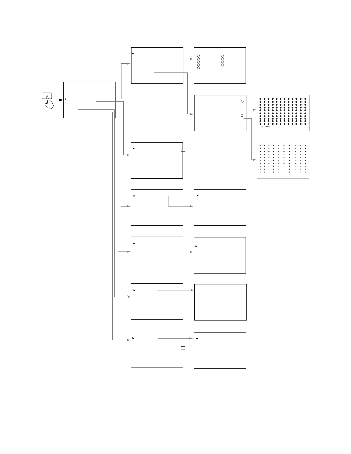
SUB M EN U ( 1) SUB MENU (2)
01137
Figure 14. Menu Tree, DX3016 Models
20 Pelco Manual C681M-D (2/02)
Page 22
(NOT USED)
01136
Figure 14. Menu Tree, DX3016 Models (Continued)
Pelco Manual C681M-D (2/02) 21
Page 23

ALARMS
IMAGE QUALITY
Skip steps 1 and 2 if they have already been done.
1. Press the SET UP button to display the Menu Setting menu.
2. Turn the JOG dial to move the cursor to A-REC/M-DET SETTING, and then turn the
3. Check that the cursor is next to IMAGE QUALITY, and then turn the SHUTTLE ring to
4. Turn the JOG dial to select the option, and then turn the SHUTTLE ring to the right.
5. Do one of the following:
SHUTTLE ring to the right. The A-Rec/M-Det Setting menu appears.
the right. The option starts flashing.
NOTE:
If the PRE A-REC field in this menu has been set to SHORT, MEDIUM,
or LONG, the option does not flash because it cannot be changed.
The option stops flashing.
Turning the JOG dial switches the image quality options as follows:
BASIC, STANDARD, MEDIUM, HIGH, SUPERIOR
•Turn the JOG dial to go to another item in this menu.
•Turn the SHUTTLE ring to the left to return to the Menu Setting menu to go to another menu.
• Press the SET UP button to exit the programming mode.
MAXIMUM RECORDING FIELDS
Skip steps 1 and 2 if they have already been done.
1. Press the SET UP button to display the Menu Setting menu.
2. Turn the JOG dial to move the cursor to A-REC/M-DET SETTING, and then turn the
SHUTTLE ring to the right. The A-Rec/M-Det Setting menu appears.
3. Turn the JOG dial to move the cursor to MAX REC FIELDS, and then turn the
SHUTTLE ring to the right. The option starts flashing.
NOTE:
or LONG, the option does not flash because it cannot be changed.
4. Turn the JOG dial to select the maximum recording fields, and then turn the SHUTTLE
ring to the right. The option stops flashing.
Turning the JOG dial switches the maximum recording fields options as follows:
DX3009 Models – 1F, 3F, 5F, 7.5F, 15F, 30F
DX3016 Models – 1F, 3F, 5F, 6F, 7.5F, 10F, 15F, 30F
NOTE:
option 30F is not available on the DX3009 models, and options 6F, 10F, and 30F
are not available on the DX3016 models.
5. Do one of the following:
If the PRE A-REC field in this menu has been set to SHORT, MEDIUM,
If the motion detection setting in the Initial Set Up menu is turned ON,
•Turn the JOG dial to go to another item in this menu.
•Turn the SHUTTLE ring to the left to return to the Menu Setting menu to go to an-
other menu.
• Press the SET UP button to exit the programming mode.
22 Pelco Manual C681M-D (2/02)
Page 24

DEFINE GROUP SETTING
Skip steps 1 and 2 if they have already been done.
1. Press the SET UP button to display the Menu Setting menu.
2. Turn the JOG dial to move the cursor to A-REC/M-DET SETTING, and then turn the
SHUTTLE ring to the right. The A-Rec/M-Det Setting menu appears.
3. Turn the JOG dial to move the cursor to DEFINE GROUP SETTING, and then turn the
SHUTTLE ring to the right. The Define Alarm Group menu appears.
4. Turn the JOG dial to move the cursor into one of the camera fields, and then turn the
SHUTTLE ring to the right. The Priority (PRI) option starts flashing.
NOTE:
If the PRE A-REC field in this menu has been set to SHORT, MEDIUM,
or LONG, the option does not flash because it cannot be changed.
5. Turn the JOG dial to select an option, and then turn the SHUTTLE ring to the right.
The option stops flashing.
Turning the JOG dial switches the priority options as follows:
1, 2, 3, 4, 5, The - (hyphen) means that camera channel is turned off; that is, if there is an alarm, it
will not be recorded.
For camera channels with a Priority setting of 1-5, the recording interval set in maxi-
mum recording fields is divided according to the value entered in the Priority setting.
The FILD (FIELDS) setting will vary according to this value.
NOTE:
When the AUDIO RECORDING setting in the Initial Set Up menu is ON,
the only options available are 1 and -.
NOTE:
When the RECORD ALARM setting in this menu is set to SEP, the only
options available are 1 and -. The FILD screen remains blank.
6. Repeat steps 4 and 5 for other cameras. Every camera channel must be assigned a
priority setting; otherwise, you will not be able to exit the menu.
7. Turn the SHUTTLE ring to the left once to return to the A-Rec/M-Det Setting menu or
twice to return to the Menu Setting menu, or press the SET UP button to exit the programming mode.
Pelco Manual C681M-D (2/02) 23
Page 25

ALARM RECORDING DURATION
Skip steps 1 and 2 if they have already been done.
1. Press the SET UP button to display the Menu Setting menu.
2. Turn the JOG dial to move the cursor to A-REC/M-DET SETTING, and then turn the
SHUTTLE ring to the right. The A-Rec/M-Det Setting menu appears.
3. Turn the JOG dial to move the cursor to A-REC DURA TION, and then turn the
SHUTTLE ring to the right. The option starts flashing.
NOTE:
If the PRE A-REC field in this menu has been set to SHORT, MEDIUM,
or LONG, the option does not flash because it cannot be changed.
4. Turn the JOG dial to select the option, and then turn the SHUTTLE ring to the right.
The option stops flashing.
Turning the JOG dial switches the alarm record duration options as follows:
DX3009 Models – MAN, 15S, 30S, 45S, 1M, 2M, 5M, 10M
DX3016 Models – MAN, 2S, 5S, 10S, 15S, 30S, 45S, 1M, 2M, 5M, 10M
MAN: Alarm recording continues until the ALARM IN terminal is cleared.
NOTE:
MAN cannot be selected when the Motion Detection setting in the Initial
Set Up menu is ON. If MAN is selected and then the motion detection setting is
turned on, MAN is automatically changed to 15S on DX3009 models and 2S on
DX3016 models.
5. Do one of the following:
•Turn the JOG dial to go to another item in this menu.
•Turn the SHUTTLE ring to the left to return to the Menu Setting menu to go to an-
other menu.
• Press the SET UP button to exit the programming mode.
RECORD ALARM
This setting determines which cameras to record when an ALARM IN terminal is grounded.
This setting is only effective during alarm recording. After alarm recording, operations return
to their prior settings.
Skip steps 1 and 2 if they have already been done.
1. Press the SET UP button to display the Menu Setting menu.
2. Turn the JOG dial to move the cursor to A-REC/M-DET SETTING, and then turn the
SHUTTLE ring to the right. The A-Rec/M-Det Setting menu appears.
3. Turn the JOG dial to move the cursor to RECORD ALARM, and then turn the
SHUTTLE ring to the right. The option starts flashing.
NOTE:
If the PRE A-REC field in this menu has been set to SHORT, MEDIUM,
or LONG, the option does not flash because it cannot be changed.
24 Pelco Manual C681M-D (2/02)
Page 26

4. Turn the JOG dial to select the option, and then turn the SHUTTLE ring to the right.
The option stops flashing.
Turning the JOG dial switches the record alarm options as follows:
ALL, SEP
ALL: Alarm recording of all cameras set to be operated on the Define Alarm Group
menu will start when the ALARM IN terminal is grounded.
SEP: Alarm recording of the camera that received the alarm signal will start. If several
cameras received an alarm input at once, all of those cameras will start alarm recording.
5. Do one of the following:
•Turn the JOG dial to go to another item in this menu.
•Turn the SHUTTLE ring to the left to return to the Menu Setting menu to go to an-
other menu.
• Press the SET UP button to exit the programming mode.
PRE-ALARM RECORDING
This setting determines if pre-alarm images will be recorded either before motion is detected or before there is an alarm signal at the ALARM IN terminal. If the pre-alarm recording option is selected, the recorder temporarily records video, but saves it only if motion is
detected or the ALARM IN terminal is activated. The duration of the saved recording depends on the settings in the MAX REC FIELDS, IMAGE QUALITY, and PRE-A REC fields.
Skip steps 1 and 2 if they have already been done.
1. Press the SET UP button to display the Menu Setting menu.
2. Turn the JOG dial to move the cursor to A-REC/M-DET SETTING, and then turn the
SHUTTLE ring to the right. The A-Rec/M-Det Setting menu appears.
3. Turn the JOG dial to move the cursor to PRE A-REC, and then turn the SHUTTLE ring
to the right. The option starts flashing.
4. Turn the JOG dial to select the option. The option stops flashing.
Turning the JOG dial switches the pre-alarm recording options as follows:
OFF, SHORT, MEDIUM, LONG
NOTE:
When SHORT, MEDIUM, or LONG is selected, the SELECT REC
MODE field in the Normal Rec Setting menu is automatically set to A-REC (Alarm
Record), and many menu settings cannot be changed.
NOTE:
The duration of recording before the alarm occurs depends on the
settings in the MAX REC FIELDS, IMAGE QUALITY, and PRE A-REC fields.
ALARM IN signal)
5. Turn the SHUTTLE ring to the right. The unit enters standby mode for pre-alarm recording, and the PRE ALARM REC indicator on the front panel illuminates (unless
OFF was selected).
Pelco Manual C681M-D (2/02) 25
Page 27

6. Do one of the following:
•Turn the JOG dial to go to another item in this menu.
•Turn the SHUTTLE ring to the left to return to the Menu Setting menu to go to an-
other menu.
• Press the SET UP button to exit the programming mode.
M-DET SETTING
Refer to
Motion Detection
for instructions.
ARCHIVE POINTER RESET
The recorder places the Archive Pointer where the archive stops. For example, 100 hours of
data recorded on the unit’s hard disk is to be transferred to a medium with only 80 hours of
available recording space. When the backup process is completed, the Archive Pointer will
memorize the hard disk’s 80-hour mark. When the next backup process is initiated, backup
will begin at this point.
If you want to reset the Archive Pointer, follow the steps below.
Skip steps 1 and 2 if they have already been done.
1. Press the SET UP button to display the Menu Setting menu.
2. Move the cursor next to SERVICE, and then turn the SHUTTLE ring to the right.
The Service menu appears.
3. Turn the JOG dial until the cursor is next to ARCHIVE POINT RESET, and then turn
the SHUTTLE ring to the right. The option starts flashing.
NOTE:
This menu item
does not appear unless an
archiving device is connected to the recorder.
4. Turn the JOG dial to select ON.
5. The message “TURN THE SHUTTLE RING >> to EXECUTE.” appears on the screen.
Turn the SHUTTLE ring to the right to reset the archive pointer. The pointer resets and
the option returns to OFF.
6. Do one of the following:
•Turn the JOG dial to go to another item in this menu.
•Turn the SHUTTLE ring to the left to return to the Menu Setting menu to go to an-
other menu.
• Press the SET UP button to exit the programming mode.
ARCHIVE
DATA
When backing up records onto backup media, it is possible to back up all data on the hard
disk drive or to select and back up only the alarm portions of the records.
Skip steps 1 and 2 if they have already been done.
1. Press the SET UP button to display the Menu Setting menu.
2. Move the cursor to INITIAL SET UP, and then turn the SHUTTLE ring to the right.
The Initial Set Up menu appears.
3. Turn the JOG dial move the cursor to ARCHIVE DA TA, and then turn the SHUTTLE
ring to the right.
26 Pelco Manual C681M-D (2/02)
Page 28

NOTE:
This menu item
does not appear unless an
archiving device is connected to the recorder.
4. Turn the JOG dial to select the option, and then turn the SHUTTLE ring to the right.
Turning the JOG dial switches the archive data options as follows:
ALL: This backs up all the data recorded on the main hard disk after the archive
pointer. Alternatively, all data will be backed up.
ALARM: Of all the data blocks recorded on the main hard disk (1 MB units), this will
back up only the data blocks that contain the alarm record. Some data on either side
of the alarm record may be included when backing up a small alarm record.
5. Do one of the following:
•Turn the JOG dial to go to another item in this menu.
•Turn the SHUTTLE ring to the left to return to the Menu Setting menu to go to an-
other menu.
• Press the SET UP button to exit the programming mode.
OVERWRITE
This setting determines whether the recorder will overwrite data on the archive medium
when making a new archive. When set to ON, all data on the archive medium will be overwritten.
Skip steps 1 and 2 if they have already been done.
1. Press the SET UP button to display the Menu Setting menu.
2. Turn the JOG dial until the cursor is next to INITIAL SET UP, and then turn SHUTTLE
ring to the right. The Initial Set Up menu appears.
3. Move the cursor to ARCHIVE OVERWRITE, and then turn the SHUTTLE ring to the
right until the option flashes.
4. Turn JOG dial to select ON or OFF, and then turn the SHUTTLE ring to the right.
The option stops flashing.
The Archive Pointer is recorded when backup is either temporarily stopped or finished.
Using the Archive Pointer, the recorder will begin the next backup at the end point of
the previous backup.
5. Do one of the following:
•Turn the JOG dial to go to another item in this menu.
•Turn the SHUTTLE ring to the left to return to the Menu Setting menu to go to an-
other menu.
• Press the SET UP button to exit the programming mode.
Pelco Manual C681M-D (2/02) 27
Page 29

AUDIO RECORDING
The recorder can record audio with an image.
Skip steps 1 and 2 if they have already been done.
1. Press the SET UP button to display the Menu Setting menu.
2. Turn the JOG dial to move the cursor to INITIAL SET UP, and then turn the SHUTTLE
ring to the right. The Initial Set Up menu appears.
3. Turn the JOG dial to select AUDIO RECORDING, and then turn the SHUTTLE ring to
the right. The option starts flashing.
NOTE:
If the PRE A-REC field in the A-Rec/M-Det Setting menu has been set to
SHORT, MEDIUM, or LONG, the option does not flash because it cannot be
changed.
4. Turn the JOG dial to select ON or OFF, and then turn the SHUTTLE ring to the right.
The option stops flashing.
NOTE:
When the audio recording setting is set to ON, the available recording
time and audio indicator (speaker icon) appear in the ESTD TIME in the Normal
Rec Setting menu. Also, on DX3009 models PRI settings of 2-5 are automatically
changed to 1 in the DEFINE GROUP setting in the Normal Rec Setting menu
and in the DEFINE ALARM GROUP setting in the A-Rec/M-Det Setting menu.
NOTE:
Depending on the setting of the image quality and the maximum
recording fields, audio recording may not be available. If so, a speaker icon with a
line through it appears next to the ESTD TIME in the Normal Rec Setting menu.
NOTE:
This menu item
does not appear unless an
archiving device is connected to the recorder.
5. Do one of the following:
•Turn the JOG dial to go to another item in this menu.
•Turn the SHUTTLE ring to the left to return to the Menu Setting menu to go to
another menu.
• Press the SET UP button to exit the programming mode.
AUTO EJECT
This setting is for automatically ejecting the medium in the archive device.
If set to ON, the medium is ejected under the following conditions:
• At the completion of the backup process
• At the end of the programmed time, if the back up is made with the timer program
• When the archive in progress is cancelled
If you set to OFF, the archive medium is not ejected.
Skip steps 1 and 2 if they have already been done.
1. Press the SET UP button to display the Menu Setting menu.
2. Turn the JOG dial to move the cursor to INITIAL SET UP, and then turn the SHUTTLE
ring to the right. The Initial Set Up menu appears.
3. Turn the JOG dial until the cursor is next to AUTO EJECT, and then turn the SHUTTLE
ring to the right. The option flashes.
4. Turn the JOG dial to select ON or OFF, and then turn the SHUTTLE ring to the right.
The option stops flashing.
28 Pelco Manual C681M-D (2/02)
Page 30

5. Do one of the following:
BUZZER
You can set the buzzer to sound under different conditions, depending on the option selected.
Skip steps 1 and 2 if they have already been done.
1. Press the SET UP button to display the Menu Setting menu.
2. Turn the JOG dial to move the cursor to REAR TERMINAL, and then turn the
3. Turn the JOG dial until the cursor is next to BUZZER, and then turn the SHUTTLE ring
4. Turn the JOG dial to select the option, and then turn the SHUTTLE ring to the right.
•Turn the JOG dial to go to another item in this menu.
•Turn the SHUTTLE ring to the left to return to the Menu Setting menu to go to an-
other menu.
• Press the SET UP button to exit the programming mode.
SHUTTLE ring to the right. The Rear Terminal menu appears.
to the right. The option flashes.
The option stops flashing.
Turning the JOG dial switches the buzzer options as follows:
KEY, WRNG, REMAIN, OFF
KEY: The buzzer sounds when any button is pressed or the JOG dial or SHUTTLE
ring is turned.
WRNG: The buzzer sounds when a warning occurs. Refer to the
REMAIN: The buzzer sounds when the remaining storage capacity of hard drive
reaches the preset amount selected in CAPACITY REMAIN. Press the WARNING RESET button to stop the buzzer.
OFF: The buzzer does not sound.
5. Do one of the following:
•Turn the JOG dial to go to another item in this menu.
•Turn the SHUTTLE ring to the left to return to the Menu Setting menu to go to an-
other menu.
• Press the SET UP button to exit the programming mode.
Warnings
section.
Pelco Manual C681M-D (2/02) 29
Page 31

CALL OUT
A signal from the CALL OUT terminal can be sent to an external device to warn when the
hard disk drive or archive device reaches the remaining capacity set in this menu. The call
out signal can also activate another recorder if the CALL OUT terminal is wired to the
record (REC) input of another recorder.
Skip steps 1 and 2 if they have already been done.
1. Press the SET UP button to display the Menu Setting menu.
2. Turn the JOG dial to move the cursor to REAR TERMINAL, and then turn the
3. Turn the JOG dial until the cursor is next to CALL OUT, and then and turn the
4. Check that the cursor is next to HDD, and then turn the SHUTTLE ring to the right.
5. Turn the JOG dial to select the option, and then turn the SHUTTLE ring to the right.
6. If an archive device is connected to the recorder, turn the JOG dial until the cursor is
SHUTTLE ring to the right. The Rear Terminal menu appears.
SHUTTLE ring to the right. The Call Out menu appears.
The option starts flashing.
The option stops flashing.
Turning the JOG dial switches the call out options as follows:
NONE, FULL, 2%, 4%, 6%, 8%, 10%, 15%, 20%, 30%, 40%, 50%
NONE: No signal is sent from the CALL OUT terminal.
next to ARCHIVE, and then turn the SHUTTLE ring to the right. The option starts
flashing.
7. Turn the JOG dial to select the option, and then turn the SHUTTLE ring to the right.
The option stops flashing.
8. Turn the SHUTTLE ring to the left once to return to the Rear Terminal menu or twice to
return to the Menu Setting menu, or press the SET UP button to exit the programming
mode.
CAPACITY REMAINING
When the remaining storage capacity of the main hard drive (HDD) or archive device
reaches the preset amount set in this menu, the recorder does the following:
•A signal is sent from the Mode Out terminal when the MODE OUT field in the Rear
Terminal menu is set to REMAIN.
• The recorded storage capacity flashes when Display Mode 3 is selected.
• The buzzer sounds when the buzzer field in the Rear Terminal menu is set to REMAIN.
Skip steps 1 and 2 if they have already been done.
1. Press the SET UP button to display the Menu Setting menu.
2. Turn the JOG dial to move the cursor to REAR TERMINAL, and then turn the
SHUTTLE ring to the right. The Rear Terminal menu appears.
3. Turn the JOG dial until the cursor is next to CAPACITY REMAIN, and then turn the
SHUTTLE ring to the right. The device option starts flashing.
30 Pelco Manual C681M-D (2/02)
Page 32

4. Turn the JOG dial to select the device.
Turning the JOG dial switches the device options as follows:
HDD, ARC, NONE
Select HDD if the MODE OUT terminal is wired to the record (REC) input of another
recorder.
5. Turn the SHUTTLE ring to the right. The percentage option starts flashing unless
NONE was selected. If NONE was selected, go to step 7.
6. Turn the JOG dial to select the percentage, and then turn the SHUTTLE ring to the
right.
Turning the JOG dial switches the percentage options as follows:
2%, 4%, 6%, 8%, 10%, 15%, 20%, 30%, 40%, 50%
If the MODE OUT terminal is wired to the record (REC) input of another recorder, the
other recorder begins recording when the storage capacity of this unit reaches the prespecified level. REMAIN must be selected in the MODE OUT field in the Rear Terminal menu.
7. Do one of the following:
•Turn the JOG dial to go to another item in this menu.
•Turn the SHUTTLE ring to the left to return to the Menu Setting menu to go to an-
other menu.
• Press the SET UP button to exit the programming mode.
DATA CLEAR (ERASE) SELECTION
This function allows you to erase data from a recording device.
Skip steps 1 and 2 if they have already been done.
1. Press the SET UP button to display the Menu Setting menu.
2. Turn the JOG dial to move the cursor to DATA CLEAR SELECTION, and then turn the
SHUTTLE ring to the right. The Data Clear Selection menu appears.
3. Turn the JOG dial to select the device, and then turn the SHUTTLE ring to the right.
The option starts flashing.
NOTE:
If the PRE A-REC field in the A-Rec/M-Det Setting menu has been set to
SHORT, MEDIUM, or LONG, the option does not flash because it cannot be
changed.
COPY DATA CLEAR or ARCHIVE DATA CLEAR appear on the screen only when a
copy device or archive device is connected.
4. Turn the JOG dial to select ON or OFF.
If you selected ON, the message, “TURN SHUTTLE RING >> to EXECUTE.” appears
on the screen. Turn the SHUTTLE ring to the right to erase the data.
If you do not want to erase data, turn the JOG dial until OFF flashes, and then turn the
SHUTTLE ring to the right.
WARNING:
If you selected HDD Data Clear, data will be erased from all
internal and external hard disk drives (ID0-ID3). Back up any data you want
to save before executing this command.
Pelco Manual C681M-D (2/02) 31
Page 33

5. Do one of the following:
•Turn the JOG dial to go to another item in this menu.
•Turn the SHUTTLE ring to the left to return to the Menu Setting menu to go to another menu.
• Press the SET UP button to exit the programming mode.
FIFO/OVERWRITE MODE (DX3016 Models Only)
Use this setting when you want to make repeated backups to a hard disk drive that is connected to ID4.
NOTE:
This menu item
does not appear unless a
hard disk drive is connected
to ID4.
Skip steps 1 and 2 if they have already been done.
1. Press the SET UP button to display the Menu Setting menu.
2. Turn the JOG dial to move the cursor to INITIAL SET UP, and then turn the SHUTTLE
ring to the right. The Initial Set Up menu appears.
3. Turn the JOG dial until the cursor is next to FIFO/OVERWRITE MODE, and then turn
the SHUTTLE ring to the right. The option starts flashing.
4. Turn the JOG dial to select ON or OFF, and then turn the SHUTTLE ring to the right.
The option stops flashing.
5. Do one of the following:
Turn the JOG dial to go to another item in this menu.
Turn the SHUTTLE ring to the left to return to the Menu Setting menu to go to another
menu.
Press the SET UP button to exit the programming mode.
BACKUP FOLLOWING A POWER FAILURE
If a power failure occurs during backup, the backup process must be started over.
Press the ARCHIVE button to restart the backup process if the recorder is not set for timer
recording or if the current time is not covered by a timer program.
If the recorder is set for timer recording and the current time is covered by a program,
backup restarts automatically after power is restored.
When the backup process is restarted, all data backed up until the power failure is lost, and
the backup pointer returns to the backup starting point before the power failure.
32 Pelco Manual C681M-D (2/02)
Page 34

HARD DISK DRIVE (HDD) FULL
When the end of the hard disk drive (HDD) is reached during recording, this function determines what the recorder will do.
Skip steps 1 and 2 if they have already been done.
1. Press the SET UP button to display the Menu Setting menu.
2. Turn the JOG dial to move the cursor to INITIAL SET UP, and then turn the SHUTTLE
ring to the right. The Initial Set Up menu appears.
3. Turn the JOG dial until the cursor is next to HDD FULL, and then turn the SHUTTLE
ring to the right. The option starts flashing.
NOTE:
If the PRE A-REC field in the A-Rec/M-Det Setting menu has been set to
SHORT, MEDIUM, or LONG, the option does not flash because it cannot be
changed.
4. Turn the JOG dial to select the option, and then turn the SHUTTLE ring to the right.
The option stops flashing.
Turning the JOG dial switches the hard drive options as follows:
REC•STANDBY (Recording standby): The unit stops recording when the hard disk is
full. The unit overwrites the hard disk when the unit receives an alarm signal, a REC
terminal signal, or when the REC button is pushed.
Select this option if the REC terminal is wired to the MODE OUT terminal of another
recorder.
REPEAT: When the disk reaches the end during recording, the recording starts again
from the beginning of the disk.
ALARM•PROT (Alarm protection): If there is any alarm recording, the unit stops recording when the hard disk is full and displays the HDD FULL message on the monitor .
When WRNG is entered as the BUZZER value (found in the Rear Terminal menu), the
buzzer is also activated.
OUT value (found in the Rear Terminal menu) is reached. If there are no alarm record-
ings, the unit continues recording by automatically overwriting the hard disk.
If the CALL OUT terminal is wired to the REC input of another recorder, the other re-
corder begins recording when the call out signal is sent.
STOP: The unit stops recording when the hard disk is full and displays the HDD FULL
message on the monitor. When WRNG is entered as the BUZZER value (found in the
Rear Terminal menu), the buzzer is also activated. The unit stops recording when there
is no more storage space in memory. A signal is sent from the CALL OUT terminal
when the CALL OUT value (found in the Rear Terminal menu) is reached. To restart
overwriting on the hard disk, press the WARNING RESET button to cancel HDD
FULL, and then press the REC button.
If the CALL OUT terminal is wired to the REC input of another recorder, the other recorder begins recording when the call out signal is sent.
5. Do one of the following:
•Turn the JOG dial to go to another item in this menu.
•Turn the SHUTTLE ring to the left to return to the Menu Setting menu to go to an-
other menu.
A signal is sent from the CALL OUT terminal when the CALL
• Press the SET UP button to exit the programming mode.
Pelco Manual C681M-D (2/02) 33
Page 35

HARD DISK DRIVE (HDD) REPEAT PLAYBACK
When the end of the hard disk drive (HDD) is reached during playback, you can set the recorder either to stop playback or to continue playback from the beginning of the disk.
Skip steps 1 and 2 if they have already been done.
1. Press the SET UP button to display the Menu Setting menu.
2. Turn the JOG dial until the cursor is next to INITIAL SET UP, and then turn the
SHUTTLE ring to the right. The Initial Set Up menu appears.
3. Turn the JOG dial until the cursor is next to HDD PB REPEAT, and then turn the
SHUTTLE ring to the right. The option starts flashing.
NOTE:
If the PRE A-REC field in the A-Rec/M-Det Setting menu has been set to
SHORT, MEDIUM, or LONG, the option does not flash because it cannot be
changed.
4. Turn the JOG dial to select REPEAT or STOP, and then turn the SHUTTLE ring to the
right. The option stops flashing.
REPEAT: At the end of the hard disk, the recorder continues playback from the beginning of the disk.
STOP: The recorder stops playback at the end of the hard disk.
5. Do one of the following:
•Turn the JOG dial to go to another item in this menu.
•Turn the SHUTTLE ring to the left to return to the Menu Setting menu to go to an-
other menu.
• Press the SET UP button to exit the programming mode.
IM-CHECK MODE
This function checks to determine if the recorded video has been altered. This function can
check the recorded video on the internal hard drive as well as video from external devices.
The authentication software analysis each frame of the video stream to verify that the
watermarking is present and that the original video has not been changed. If an image is
modified, a small black square appears in the modified area of the image. If the image is
an alarm, a small black square also appears on the screen next to the alarm number.
The message “WARNING: MODIFIED IMAGE” appears on the screen along with the numbers of the affected cameras.
Skip steps 1 and 2 if they have already been done.
1. Press the SET UP button to display the Menu Setting menu.
2. Move the cursor next to SERVICE, and then turn the SHUTTLE ring to the right.
The Service menu appears.
3. Turn the JOG dial until the cursor is next to IM-CHECK MODE, and then turn the
SHUTTLE ring to the right. The option starts flashing.
NOTE:
If the PRE A-REC field in the A-Rec/M-Det Setting menu has been set to
SHORT, MIDDLE, or LONG, the option does not flash because it cannot be
changed.
4. Turn the JOG dial to select ON or OFF, and then turn the SHUTTLE ring to the right.
The option stops flashing.
34 Pelco Manual C681M-D (2/02)
Page 36

5. Do one of the following:
•Turn the JOG dial to go to another item in this menu.
•Turn the SHUTTLE ring to the left to return to the Menu Setting menu to go to
another menu.
• Press the SET UP button to exit the programming mode.
INITIALIZE MENUS
Initializing the menus returns most settings to their default values.
Skip steps 1 and 2 if they have already been done.
1. Press the SET UP button to display the Menu Setting menu.
2. Turn the JOG dial to move the cursor to SERVICE, and then turn the SHUTTLE ring to
the right. The Service menu appears.
3. Turn the JOG dial until the cursor is next to MENU INITIALIZE, and then turn the
SHUTTLE ring to the right. The option starts flashing.
NOTE:
If the PRE A-REC field in the A-Rec/M-Det Setting menu has been set to
SHORT, MEDIUM, or LONG, the option does not flash because it cannot be
changed.
4. Turn the JOG dial to select ON or OFF.
5. If you selected ON, “PUSH WARNING RESET KEY THEN ALL MENU WILL BE INITIALIZED.” appears on the screen. Press the WARNING RESET button. The 9-camera
screen (DX3009 models) or 16-camera screen (DX3016 models) appears on the
monitor and menus are reset to their default values, except for the time and date display, timer program settings, and camera titles. The Selected Pattern setting is set to
P1 in the Timer Program. The Menu Initialize option returns to OFF and stops flashing.
6. Do one of the following:
MODE OUT
With this setting, a signal can be output to indicate the status of the recorder.
Skip steps 1 and 2 if they have already been done.
1. Press the SET UP button to display the Menu Setting menu.
2. Turn the JOG dial to move the cursor to REAR TERMINAL, and then turn the
3. Check that the cursor is next to MODE OUT, and then turn the SHUTTLE ring to the
If you selected OFF, turn the SHUTTLE ring to the right. The option stops flashing.
•Turn the JOG dial to go to another item in this menu.
•Turn the SHUTTLE ring to the left to return to the Menu Setting menu to go to an-
other menu.
• Press the SET UP button to exit the programming mode.
SHUTTLE ring to the right. The Rear Terminal menu appears.
right. The option starts flashing.
Pelco Manual C681M-D (2/02) 35
Page 37

4. Turn the JOG dial to select the option, and then turn the SHUTTLE ring to the right.
The option stops flashing.
Turning the JOG dial switches the mode out options as follows:
REC, PLAY, POWER, REMAIN
REC: The signal is output during recording.
PLAY: The signal is output during playback.
POWER: The signal is output when the recorder’s power switch is on.
REMAIN: The signal is output when the remaining storage capacity of main hard
drive, archive device, or copy device reaches the rate which is set in the CAPACITY
REMAIN field of the Rear Terminal menu.
Select REMAIN if the MODE OUT terminal is wired to the record (REC) input of another recorder.
5. Do one of the following:
•Turn the JOG dial to go to another item in this menu.
•Turn the SHUTTLE ring to the left to return to the Menu Setting menu to go to an-
other menu.
• Press the SET UP button to exit the programming mode.
MOTION DETECTION
NOTE:
To set up motion
detection to operate during
a specified time period
(DX3016 models only), refer
to the section on
Motion
Detection During a Timer
Recording
.
These settings are used to initiate alarm recording when movement is detected within the
images captured by the cameras.
Skip steps 1 and 2 if they have already been done.
1. Press the SET UP button to display the Menu Setting menu.
2. Turn the JOG dial to move the cursor to INITIAL SET UP, and then turn the SHUTTLE
ring to the right. The Initial Set Up menu appears.
3. Turn the JOG dial to select MOTION DETECTION, and then turn the SHUTTLE ring to
the right. The option starts flashing.
NOTE:
If the PRE A-REC field in the A-Rec/M-Det Setting menu has been set to
SHORT, MEDIUM, or LONG, the option does not flash because it cannot be
changed.
4. Turn the JOG dial to select ON or OFF, and then turn the SHUTTLE ring to the right.
The option stops flashing.
If you selected ON, proceed to step 5.
If you selected OFF, turn the SHUTTLE ring to the left to return to the Menu Setting
menu to go to another menu, or press the SET UP button to exit the programming
mode.
5. Turn the SHUTTLE ring to the left to return to the Menu Setting menu
6. Turn the JOG dial to select A-REC/M-DET SETTING, and then turn the SHUTTLE ring
to the right. The A-REC/M-DET SETTING menu appears.
.
NOTE:
The image quality, maximum recording fields, and alarm recording dura-
tion in the A-Rec/M-Det Setting menu also apply to motion detection recordings.
36 Pelco Manual C681M-D (2/02)
Page 38

7. Turn the JOG dial to select the M-DET SETTING, and then turn the SHUTTLE ring to
the right. The Motion menu appears. This menu will not appear if the MOTION DETECTION setting in the Initial Set Up menu is OFF.
8. Check that the cursor is next to SELECTION CAMERA NO., and then turn the
SHUTTLE ring to the right. The option starts flashing.
9. Turn the JOG dial to select the camera number, and then turn the SHUTTLE ring to
the right. The option stops flashing.
When the camera selection setting has been made, the background display switches
to the selected camera. Exiting the menu reverts the display to its original state.
Make sure the camera is also selected in the DEFINE GROUP SETTING in the
A-Rec/M-Det Setting menu.
10. Turn the JOG dial to select CH. MOTION DETECTION, and then turn the SHUTTLE
ring to the right. The option starts flashing.
11.Turn the JOG dial to select ON or OFF, and then turn the SHUTTLE ring to the right.
The option stops flashing.
If you selected ON, proceed to the next step.
If you selected OFF, return to step 8 to select another camera. Otherwise, turn the
SHUTTLE ring to the left once to return to the A-Rec/M-Det Setting menu, twice to return to the Menu Setting menu, or press the SET UP button to exit the programming
mode.
12. Turn the JOG dial to select the SET DETECTION MASK, and then turn the SHUTTLE
ring to the right. The Set Detection Mask menu appears. The mask is a 10 x 12 grid of
120 dots.
13. Set the detection mask.
“
” : Active symbol (Indicates the area where motion detection is active.)
•
“•” : Inactive symbol (Indicates the area where motion detection is inactive.)
Turn the JOG dial to change the symbol.
To move to the left, press camera button 6.
To move to the right, press camera button 7.
To move up, press camera button 8.
To move down, press camera button 9.
To select the entire screen, press camera button 4.
To deselect the entire screen, press camera button 5.
14. Turn the SHUTTLE ring to the left when you are finished setting the detection mask.
15. Turn the JOG dial to select SENSITIVITY, and then turn the SHUTTLE ring to the
right. The option starts flashing.
16. Turn the JOG dial to select the option, and then turn the SHUTTLE ring to the right.
The option stops flashing.
Turning the JOG dial switches the sensitivity options as follows:
LOW, LOWER, HIGHER, HIGH, MED
The camera’s image data is sampled and compared every 0.6 seconds. Sensitivity is
the difference in the degree of brightness between the sampled images and is divided
into settings of five different levels. Select HIGHER to make the unit sensitive to even
the smallest changes. Note, however, that false alarms may be caused by, for example,
the flickering of fluorescent lighting fixtures.
17. Turn the JOG dial to select MOTION THRESHOLD, and then turn the SHUTTLE ring
to the right. The option starts flashing.
Pelco Manual C681M-D (2/02) 37
Page 39

18. Turn the JOG dial to select the threshold, and then turn the SHUTTLE ring to the right.
The option stops flashing.
Select a number between 1 and 120. The number is the minimum number of active
dots required to initiate alarm recording.
When establishing a value for the motion threshold setting, use a value that does not
exceed the number of active dots set for the motion detection function. Alarm recording will not operate if a larger value is used.
19. This step and the next step verify the motion detection settings. Turn the JOG dial to
select TEST MODE, and then turn the SHUTTLE ring to the right. The option starts
flashing.
20. Turn the JOG dial to display ON, and then turn the SHUTTLE ring to the right. The test
screen appears. The area where motion detection has been activated is displayed using “•”. When motion is detected on the number of dots specified in the motion threshold setting, the active symbol “
21. Turn the SHUTTLE ring to the left to exit the test screen. Redo the settings if the recorder does not operate as intended.
22. Do one of the following:
• Return to step 8 to select another camera.
•Turn the SHUTTLE ring to the left once to return to the A-Rec/M-Det Setting
menu or twice to return to the Menu Setting menu.
• Press the SET UP button to exit the programming mode.
” appears on the screen.
•
MULTIPLEXER DISPLAY
By using the multiplexer functions, you can view 4, 9, or 16 cameras on your monitor.
You can also arrange the viewing order of cameras.
SPLIT SCREEN SETTING (DX3009 Models Only)
Nine-Camera (Split 9) Setting
Skip steps 1 and 2 if they have already been done.
1. Press the SET UP button to display the Menu Setting menu.
2. Turn the JOG dial to move the cursor to MPX DISPLAY, and then turn the SHUTTLE
ring to the right. The MPX Display menu appears.
3. Check that the cursor is next to SPLIT SCREEN SETTING, and then turn the
SHUTTLE ring to the right. The Split Screen Setting menu appears.
4. Make sure that the cursor is next to SPLIT 9, and then turn the SHUTTLE ring to the
right. The top left number starts flashing.
5. Turn the JOG dial to display the desired camera number, and then turn the SHUTTLE
ring to the right. The next camera number starts flashing. If you do not want to change
the number, just turn the SHUTTLE ring to the right.
6. Repeat step 5 for all other cameras. You cannot use the same camera number more
than once.
7. Turn the SHUTTLE ring to the left once to return to the MPX Display menu or twice to
return to the Menu Setting menu, or press the SET UP button to exit the programming
mode.
38 Pelco Manual C681M-D (2/02)
Page 40

Four-Camera (Split 4) Setting
In the SPLIT 4 setting mode, you select which camera images to show in a four-camera
display. Three different groups of cameras can be defined.
Skip steps 1-3 if they have already been done.
1. Press the SET UP button to display the Menu Setting menu.
2. Turn the JOG dial to move the cursor to MPX DISPLAY, and then turn the SHUTTLE
ring to the right. The MPX Display menu appears.
3. Check that the cursor is next to SPLIT SCREEN SETTING, and then turn the
SHUTTLE ring to the right. The Split Screen Setting menu appears.
4. Turn the JOG dial to move the cursor to SPLIT4a, and then turn the SHUTTLE ring to
the right. The top left number starts flashing.
5. Turn the JOG dial to display the desired camera number, and then turn the SHUTTLE
ring to the right. The next camera number starts flashing. If you do not want to change
the number, just turn the SHUTTLE ring to the right.
6. Repeat step 5 for the other three cameras. Y ou cannot use the same camera number
more than once in the same group.
7. Repeat steps 4-6 for SPLIT 4b and SPLIT 4c.
8. Turn the SHUTTLE ring to the left once to return to the MPX Display menu or twice to
return to the Menu Setting menu, or press the SET UP button to exit the programming
mode.
SCREEN SWITCH PATTERN (DX3016 Models Only)
Skip steps 1 and 2 if they have already been done.
1. Press the SET UP button to display the Menu Setting menu.
2. Turn the JOG dial to move the cursor next to MPX DISPLAY, and then turn the
SHUTTLE ring to the right. The MPX Display menu appears.
3. Check that the cursor is next to SPLIT SW PATTERN, and then turn the SHUTTLE
ring to the right. The option starts flashing.
4. Turn the JOG dial to select the option, and then turn the SHUTTLE ring to the right.
The option stops flashing.
Turning the JOG dial switches the options as follows:
ALL: All the display modes and sequential display modes for SPLIT 16, SPLIT 9,
SPLIT 4, and single screens can be selected.
SHORT: Single-screen, SPLIT 4, and SPLIT 9 sequential displays can be selected.
By combining SEQUENCE with the split-screen display setting, a fixed split-screen
display pattern can be established. In this case, only SPLIT 16 can be selected during
playback.
5. Do one of the following:
•Turn the JOG dial to go to another item in this menu.
•Turn the SHUTTLE ring to the left to return to the Menu Setting menu to go to an-
other menu.
• Press the SET UP button to exit the programming mode.
Pelco Manual C681M-D (2/02) 39
Page 41

SPLIT 4 SCREEN SETTING (DX3016 Models Only)
In the Split 4 Screen Setting, you select which camera images to show in a four-camera
display. Four different groups of cameras can be defined.
Skip steps 1 and 2 if they have already been done.
1. Press the SET UP button to display the Menu Setting menu.
2. Turn the JOG dial to move the cursor next to MPX DISPLAY, and then turn the
SHUTTLE ring to the right. The MPX Display menu appears.
3. Turn the JOG dial to move the cursor next to SPLIT 4 SCREEN SETTING, and then
turn the SHUTTLE ring to the right. The Split4 Screen Setting menu appears.
4. Make sure the cursor is next to SPLIT4a, and then turn the SHUTTLE ring to the right.
The top left number starts flashing.
5. Turn the JOG dial to display the desired camera number, and then turn the SHUTTLE
ring to the right. The next camera number starts flashing. If you do not want to change
the camera number, just turn the SHUTTLE ring to the right.
6. Repeat step 5 for the other three cameras. Y ou cannot use the same camera number
more than once in the same group.
7. Repeat steps 4-6 for SPLIT 4b, SPLIT 4c, and SPLIT 4d.
8. Turn the SHUTTLE ring to the left once to return to the MPX Display menu or twice to
return to the Menu Setting Menu, or press the SET UP button to exit the programming
mode.
SPLIT 9 SCREEN SETTING (DX3016 Models Only)
In the Split 9 Screen Setting, you select which camera images to show in a nine-camera
display. T wo dif ferent groups of cameras can be defined.
Skip steps 1 and 2 if they have already been done.
1. Press the SET UP button to display the Menu Setting menu.
2. Turn the JOG dial to move the cursor next to MPX DISPLAY, and then turn the
SHUTTLE ring to the right. The MPX Display menu appears.
3. Turn the JOG dial to move the cursor next to SPLIT 9 SCREEN SETTING, and then
turn the SHUTTLE ring to the right. The Split9 Screen Setting menu appears.
4. Make sure the cursor is next to SPLIT9a, and then turn the SHUTTLE ring to the right.
The top left number starts flashing.
5. Turn the JOG dial to display the desired camera number, and then turn the SHUTTLE
ring to the right. The next camera number starts flashing. If you do not want to change
the camera number, just turn the SHUTTLE ring to the right.
6. Repeat step 5 for the other eight cameras. You cannot use the same camera number
more than once in the same group.
7. Repeat steps 4-6 for SPLIT 9b.
8. Turn the SHUTTLE ring to the left once to return to the MPX Display menu or twice to
return to the Menu Setting Menu, or press the SET UP button to exit the programming
mode.
40 Pelco Manual C681M-D (2/02)
Page 42

SPLIT 16 SCREEN SETTING (DX3016 Models Only)
Skip steps 1 and 2 if they have already been done.
1. Press the SET UP button to display the Menu Setting menu.
2. Turn the JOG dial to move the cursor next to MPX DISPLAY, and then turn the
SHUTTLE ring to the right. The MPX Display menu appears.
3. Turn the JOG dial to move the cursor next to SPLIT 16 SCREEN SETTING, and then
turn the SHUTTLE ring to the right. The Split16 Screen Setting menu appears.
4. Make sure the cursor is next to SPLIT16, and then turn the SHUTTLE ring to the right.
The top left number starts flashing.
5. Turn the JOG dial to display the desired camera number, and then turn the SHUTTLE
ring to the right. The next camera number starts flashing. If you do not want to change
the camera number, just turn the SHUTTLE ring to the right.
6. Repeat step 5 for the other 15 cameras. Y ou cannot use the same camera number
more than once.
7. Turn the SHUTTLE ring to the left once to return to the MPX Display menu or twice to
return to the Menu Setting Menu, or press the SET UP button to exit the programming
mode.
IMAGE QUALITY
It is possible to set the image quality when viewing multiple cameras.
Skip steps 1 and 2 if they have already been done.
1. Press the SET UP button to display the Menu Setting menu.
2. Turn the JOG dial to move the cursor to MPX DISPLAY, and then turn the SHUTTLE
ring to the right. The MPX Display menu appears.
3. Turn the JOG dial to move the cursor to IMAGE QUALITY , and then turn the SHUTTLE
ring to the right. The option flashes.
HIGH: Fine details are visible.
NO FLICKER: Screen flicker is reduced. Vertical resolution may be slightly degraded.
4. Turn the JOG dial to choose the option, and then turn the SHUTTLE ring to the right.
The option stops flashing.
5. Do one of the following:
•Turn the JOG dial to go to another item in this menu.
•Turn the SHUTTLE ring to the left to return to the Menu Setting menu to go to an-
other menu.
• Press the SET UP button to exit the programming mode.
Pelco Manual C681M-D (2/02) 41
Page 43

SEQUENCE
Cameras can be sequenced individually, in groups of four cameras, or, for the DX3016
models only, in groups of nine cameras. Set all sequence patterns. These are the patterns
that will be displayed when the SPLIT/SEQUENCE button is pushed (refer to the
section).
Skip steps 1 and 2 if they have already been done.
1. Press the SET UP button to display the Menu Setting menu.
2. Turn the JOG dial to move the cursor to MPX DISPLAY, and then turn the SHUTTLE
ring to the right. The MPX Display menu appears.
3. Turn the JOG dial to move the cursor to SEQUENCE, and then turn the SHUTTLE
ring to the right. The Sequence menu appears. The cursor is beside channel (camera)
1 in the nine-camera sequence.
4. Turn the JOG dial to select the desired channel number, and then turn the SHUTTLE
ring to the right. The channel number starts flashing.
5. Turn the JOG dial until the desired channel number appears, and then turn the
SHUTTLE ring to the right. The time starts flashing.
6. Turn the JOG dial to display the desired length of time that the camera’s image will be
shown before switching to the next camera, and then turn the SHUTTLE ring to the
right. The option stops flashing.
The time can be set from 1 to 30 seconds.
7. Repeat steps 4, 5, and 6 to enter settings for the other cameras in the 9-camera or
16-camera sequence. The same camera can be entered in the sequence repeatedly.
If you have a DX3016 model, turn the JOG dial when the cursor is on channel 9 to
scroll to the next screen.
Operation
8. Turn the JOG dial to move the cursor to SPLIT 4, and then turn the SHUTTLE ring to
the right. The option starts flashing.
9. Turn the JOG dial to select the pattern: ab or abc for DX3009 models and a, ab, abc,
or abcd or DX3016 models. The letters a, b, c, and d refer to the Split 4 settings in the
Split Screen Setting in the MPX Display menu.
10. Turn the SHUTTLE ring to the right. The time starts flashing.
11.Turn the JOG dial to display the desired length of time that the quad image will be
shown before switching to the next quad display, and then turn the SHUTTLE ring to
the right. The option stops flashing.
The time can be set from 1 to 30 seconds.
12. DX3016 Models Only – Repeat steps 8-11 to set the SPLIT9 settings. The two
patterns are a and ab.
13. Turn the SHUTTLE ring to the left once (twice for DX3016 models) to return to the
MPX Display menu or twice (three times for DX3016 models) to return to the Menu
Setting menu, or press the SET UP button to exit the programming mode.
CHANNEL TITLE (Displaying Camera Title and/or Number)
You can choose whether to display the camera (channel) title and/or camera number on the
screen.
Skip steps 1 and 2 if they have already been done.
1. Press the SET UP button to display the Menu Setting menu.
2. Turn the JOG dial to move the cursor to MPX DISPLAY, and then turn the SHUTTLE
ring to the right. The MPX Display menu appears.
42 Pelco Manual C681M-D (2/02)
Page 44

3. Turn the JOG dial to move the cursor to CH.TITLE, and then turn the SHUTTLE ring
to the right. The option starts flashing.
NOTE:
If the PRE A-REC field in the A-Rec/M-Det Setting menu has been set to
SHORT, MEDIUM, or LONG, the option does not flash because it cannot be
changed.
4. Turn the JOG dial to select the option, and the turn the SHUTTLE ring to the right to
finish setting.
Turning the JOG dial switches the title options as follows:
NONE, TITLE, CH. NO
NONE: Camera numbers and titles are not displayed.
TITLE: Camera numbers and titles are displayed.
CH. NO: Only camera numbers are displayed.
5. Do one of the following:
•Turn the JOG dial to go to another item in this menu.
•Turn the SHUTTLE ring to the left to return to the Menu Setting menu to go to an-
other menu.
• Press the SET UP button to exit the programming mode.
ALARM DISPLAY
When the unit receives an alarm input signal, the monitor displays images from the camera
with the alarm. If, during alarm recording, the recorder receives another alarm input signal,
the monitor displays images from the latest alarm recording camera channel. (The display
is single-camera mode.) The monitor returns to its original display mode after alarm recording is completed.
Skip steps 1 and 2 if they have already been done.
1. Press the SET UP button to display the Menu Setting menu.
2. Turn the JOG dial to move the cursor to MPX DISPLAY, and then turn the SHUTTLE
ring to the right. The MPX Display menu appears.
3. Turn the JOG dial to move the cursor to ALARM DISPLAY, and then turn the
SHUTTLE ring to the right. The option starts flashing.
NOTE:
If the PRE A-REC field in the A-Rec/M-Det Setting menu has been set to
SHORT, MEDIUM, or LONG, the option does not flash because it cannot be
changed.
4. Turn the JOG dial to select ON or OFF, and then turn the SHUTTLE ring to the right.
The option stops flashing.
5. Do one of the following:
•Turn the JOG dial to go to another item in this menu.
•Turn the SHUTTLE ring to the left to return to the Menu Setting menu to go to an-
other menu.
• Press the SET UP button to exit the programming mode.
Pelco Manual C681M-D (2/02) 43
Page 45

CAMERA TITLE
Titles can be added for each camera. In single-camera display mode, up to 16 characters
can be displayed. In four-camera display mode, the first 8 characters are displayed. Titles
cannot be displayed in nine-camera or sixteen-camera display mode. In addition, displayed
titles do not get recorded.
Skip steps 1 and 2 if they have already been done.
1. Press the SET UP button to display the Menu Setting menu.
2. Turn the JOG dial to move the cursor to MPX DISPLAY, and then turn the SHUTTLE
ring to the right. The MPX Display menu appears.
3. Turn the JOG dial to move the cursor to CAMERA TITLE, and then turn the SHUTTLE
ring to the right.
4. Turn the JOG dial to the right to move the cursor next to camera number, and then
turn the SHUTTLE ring to the right. The first character position of the TITLE setting
flashes.
NOTE:
If the PRE A-REC field in the A-Rec/M-Det Setting menu has been set to
SHORT, MEDIUM, or LONG, the option does not flash because it cannot be
changed.
DX3016 Models Only – The Camera Tile menu has two screens. When the cursor
is on camera 8, turn the JOG dial to the right to scroll to the next screen.
5. Turn the JOG dial to display the desired character, and then turn the SHUTTLE ring to
the right to move to the next position.
Turning the SHUTTLE ring to the left erases the character.
6. Repeat step 5 to finish entering the word. To exit the TITLE row, move the flashing
cursor to the right end, and then turn the SHUTTLE ring to the right.
7. Repeat steps 4-6 to enter other titles.
8. Turn the SHUTTLE ring to the left once (twice for DX3016 models) to return to the
MPX Display menu or twice (three times for DX3016 models) to return to the Menu
Setting menu, or press the SET UP button to exit the programming mode.
You cannot exit the menu if any TITLE character is flashing. Refer to step 6 to exit.
POWER FAILURE
There is nothing to program in this screen. It lists power failures. Refer to
the
Operation
RECORD
IMAGE QUALITY
Skip steps 1 and 2 if they have already been done.
1. Press the SET UP button to display the Menu Setting menu.
2. Turn the JOG dial to move the cursor to NORMAL REC SETTING, and then turn the
SHUTTLE ring to the right. The Normal Rec Setting menu appears.
3. Check that the cursor is next to IMAGE QUALITY, and then turn the SHUTTLE ring to
the right. The Image Quality option starts flashing.
section.
Power Failure
in
NOTE:
If the PRE A-REC field in the A-Rec/M-Det Setting menu has been set to
SHORT, MEDIUM, or LONG, this field cannot be changed.
44 Pelco Manual C681M-D (2/02)
Page 46

4. Turn the JOG dial to select the option, and then turn the SHUTTLE ring to the right.
The flashing stops.
Turning the JOG dial changes the image quality setting as follows:
BASIC, STANDARD, MEDIUM, HIGH, SUPERIOR
5. Do one of the following:
•Turn the JOG dial to go to another item in this menu.
•Turn the SHUTTLE ring to the left to return to the Menu Setting menu to go to an-
other menu.
• Press the SET UP button to exit the programming mode.
MAXIMUM RECORDING FIELDS
Skip steps 1 and 2 if they have already been done.
1. Press the SET UP button to display the Menu Setting menu.
2. Turn the JOG dial to move the cursor to NORMAL REC SETTING, and then turn the
SHUTTLE ring to the right. The Normal Rec Setting menu appears.
3. Turn the JOG dial and move the cursor to MAX REC FIELDS, and then turn the
SHUTTLE ring to the right. The option starts flashing.
NOTE:
If the PRE A-REC field in the A-Rec/M-Det Setting menu has been set to
SHORT, MEDIUM, or LONG, this field cannot be changed.
4. Turn the JOG dial to select the option, and then turn the SHUTTLE ring to the right.
The option stops flashing.
Turning the JOG dial changes the maximum recording fields as follows:
DX3009 Models – 1F, 3F, 5F, 7.5F, 15F, 30F
DX3016 Models – 1F, 3F, 5F, 6F, 7.5F, 10F, 15F, 30F
NOTE:
If the motion detection setting in the Initial Set Up menu is turned ON,
option 30F is not available on the DX3009 models, and options 6F, 10F , and 30F
are not available on the DX3016 models.
Changing the recording setting changes the estimated recording time at the bottom of
the screen. (The alarm recording setting does not affect the estimated recording time).
The available recording time changes depending on the settings of the image quality
and maximum recording fields. The estimated recording time display will include all
hard disk drives. The estimated time may not show the exact time if the recording
interval was set too long. For available recording times, refer to the
Table
section.
5. Do one of the following:
•Turn the JOG dial to go to another item in this menu.
•Turn the SHUTTLE ring to the left to return to the Menu Setting menu to go to an-
other menu.
• Press the SET UP button to exit the programming mode.
Recording Time
Pelco Manual C681M-D (2/02) 45
Page 47

SELECT RECORDING MODE
There are three recording modes: A, B, and C. For example, mode A might be used for
daytime recording, mode B for nighttime recording, and mode C for weekend recording.
The cameras that will record in each mode are selected in the next section,
The settings made for image quality and maximum recording fields apply to all three
modes.
Skip steps 1 and 2 if they have already been done.
1. Press the SET UP button to display the Menu Setting menu.
2. Turn the JOG dial to move the cursor to NORMAL REC SETTING, and then turn the
SHUTTLE ring to the right. The Normal Rec Setting menu appears.
3. Turn the JOG dial to move the cursor to SELECT REC MODE, and then turn the
SHUTTLE ring to the right. The option starts flashing
NOTE:
When SHORT, MEDIUM, or LONG is selected in the PRE A-REC field in
.
the A-Rec/M-Det Setting menu, the SELECT REC MODE field is automatically
set to A-REC (Alarm Record) and cannot be changed.
4. Turn the JOG dial to select mode A, B, or C, and then turn the SHUTTLE ring to the
right. The option stops flashing.
5. Do one of the following:
•Turn the JOG dial to go to another item in this menu.
•Turn the SHUTTLE ring to the left to return to the Menu Setting menu to go to an-
other menu.
Define Group
.
• Press the SET UP button to exit the programming mode.
DEFINE GROUP
In the Define Group Setting menu selection, you choose which cameras will record during
the mode (A, B, or C) that was picked in the Select Recording Mode field. A camera can be
used in more than one mode.
Skip steps 1 and 2 if they have already been done.
1. Press the SET UP button to display the Menu Setting menu.
2. Turn the JOG dial to move the cursor to NORMAL REC SETTING, and then turn the
SHUTTLE ring to the right. The Normal Rec Setting menu appears.
3. Turn the JOG dial to move the cursor to DEFINE GROUP SETTING, and then turn the
SHUTTLE ring to the right. The Define Group menu appears.
NOTE:
If the PRE A-REC field in the A-Rec/M-Det Setting menu has been set to
SHORT, MEDIUM, or LONG, the menu channot be accessed.
4. Turn the JOG dial to select the camera channel, and then turn the SHUTTLE ring to
the right. The option starts flashing.
46 Pelco Manual C681M-D (2/02)
Page 48

5. Turn the JOG dial to select the option, and then turn the SHUTTLE ring to the right.
The option stops flashing.
Turning the JOG dial changes the priority setting as follows:
1, 2, 3, 4, 5, The - (hyphen) means that camera channel is turned off; that is, if a camera is con-
nected to the DVR, it will not be recorded.
For camera channels with a Priority setting of 1-5, the recording interval set in maxi-
mum recording fields is divided according to the value entered in the Priority setting.
The FILD (FIELDS) setting will vary according to this value.
NOTE:
When the AUDIO RECORDING setting in the Initial Set Up menu is ON,
the only options available are 1 and -.
6. Repeat steps 4 and 5 for other cameras. Every camera channel must have a priority
setting; otherwise, you will not be able to exit the menu.
7. Turn the SHUTTLE ring to the left once to return to the Normal Rec Setting menu or
twice to return to the Main Setting menu, or press the SET UP button to exit the programming mode.
RS-232C COMMUNICATION
The recorder can be operated from a personal computer connected to the RS-232C terminal.
These settings set the communication parameters.
Pelco does not offer equipment to support this function.
Skip steps 1 and 2 if they have already been done.
1. Press the SET UP button to display the Menu Setting menu.
2. Turn the JOG dial to move the cursor to COMMUNICATION SETTING, and then turn
the SHUTTLE ring to the right. The Communication Setting menu appears.
3. Check that the cursor is next to RS-232C SETTING, and then turn the SHUTTLE ring
to the right. The RS-232C Setting menu appears.
4. Check that the cursor is next to TRANSMISSION RATE, and then turn the SHUTTLE
ring to the right. The option starts flashing.
NOTE:
If the PRE A-REC field in the A-Rec/M-Det Setting menu has been set to
SHORT, MEDIUM, or LONG, the option does not flash because it cannot be
changed.
5. Turn the JOG dial to select the baud rate, and then turn the SHUTTLE ring to the right.
The options are 1200, 2400, 4800, and 9600.
6. Repeat steps 4 and 5 for the data bit length, parity, stop bit length, and delimiter.
The options for each field:
Data bit length: 7 or 8
Parity: None, odd, even
Stop bit length: 1 or 2
Delimiter: CR (carriage return) or CR•LF (carriage return and line feed)
7. Turn the SHUTTLE ring to the left once to return to the Communication Setting menu
or twice to return to the Menu Setting menu, or press the SET UP button to exit the
programming mode.
Pelco Manual C681M-D (2/02) 47
Page 49

SAVING MENU SETTINGS
Complex menu settings can be saved on a peripheral recording device connected to SCSI
ID number 5. These settings also can be read by the recorder from the peripheral device.
SAVING MENU DATA
If you have previously saved menu settings, saving them again will overwrite the current
settings on the peripheral device.
1. Make sure the recorder is turned off.
2. Press and hold the ARCHIVE button, and then press the POWER button to turn the
power on. Release the ARCHIVE button. The Quick Setting menu appears. The Power
button blinks and the recorder will not perform any other functions until you complete this
procedure.
3. Turn the JOG dial to select Menu Data Saving, and then turn the SHUTTLE ring to the
right when “TURN THE SHUTTLE RING >> TO EXECUTE.” appears on the screen.
NOTE:
If a peripheral device is not connected to ID5, the only option is POWER
OFF. Turn the SHUTTLE ring to the right twice to turn off the power, and then turn
the power back on.
4. Turn the SHUTTLE ring twice to the right. “SAVING. . .” appears while the data is being saved, and “COMPLETED.” appears when the process is finished.
5. Turn the SHUTTLE ring to the left. The “COMPLETED.” message disappears.
6. Turn the JOG dial to select Power Off, and then turn the SHUTTLE ring to the right.
The power is turned off.
RESTORING MENU DATA
Copying menu settings from a peripheral device overwrites current menu settings in the
recorder.
1. Make sure the recorder is turned off.
2. Press and hold the ARCHIVE button, and then press the POWER button to turn the
power on. Release the ARCHIVE button. The Quick Setting menu appears. The Power
button blinks and the recorder will not perform any other functions until you complete this
procedure.
3. Turn the JOG dial to select Menu Data Loading, and then turn the SHUTTLE ring to
the right when “TURN THE SHUTTLE RING >> TO EXECUTE.” appears on the
screen.
NOTE:
OFF. Turn the SHUTTLE ring to the right twice to turn off the power, and then turn
the power back on.
If a peripheral device is not connected to ID5, the only option is POWER
4. Turn the SHUTTLE ring twice to the right. “LOADING. . .” appears while the data is being read, and “COMPLETED.” appears when the process is finished.
5. Turn the SHUTTLE ring to the left. The “COMPLETED.” message disappears.
6. Turn the JOG dial to select Power Off, and then turn the SHUTTLE ring to the right.
The power is turned off.
48 Pelco Manual C681M-D (2/02)
Page 50

TCP/IP SETTING (DX3016 Models Only)
This menu is not used.
TIME AND DATE DISPLAY
DISPLAY MODE
Skip steps 1 and 2 if they have already been done.
1. Press the SET UP button to display the Menu Setting menu.
2. Make sure the cursor is next to TIME DATE DISPLAY, and then turn the SHUTTLE
ring to the right. The Time Date Display menu appears.
3. Make sure the cursor is next to DISPLAY MODE, and then turn the SHUTTLE ring to
the right. The current option starts flashing.
Pelco Manual C681M-D (2/02) 49
Page 51

4. Turn the JOG dial to select 1-6, and then turn the SHUTTLE ring to the right. The option
stops flashing. An example of the display mode appears on the screen, as shown in
the chart below.
Display Mode
Date, present time, and camera
1
number
Date, day of the week, present time,
recording interval, and camera
2
number
Date, day of the week, present time,
Recording interval, recording capacity
3
of HDD, and camera number
No indication
(When alarm signal is input, date, day of
4
the week, present time, and recording
interval will be displayed.)
No indication
(When warning signal is received,
5
warning indicator will be displayed.)
No indication
6
Display modes 2 to 5 are only available when single screen is displayed or
CH. TITLE is set to NONE in the MPX Display menu.
Display Sample
06-09-2000 11:39:10 C1
06-09-2000 FRI
11:39:10 12.5F C1
06-09-2000 FRI
11:39:10 12.5F 99C1%
01135
5. Do one of the following:
•Turn the JOG dial to go to another item in this menu.
•Turn the SHUTTLE ring to the left to return to the Menu Setting menu to go to an-
other menu.
• Press the SET UP button to exit the programming mode.
CHARACTER SIZE
Skip steps 1 and 2 if they have already been done.
1. Press the SET UP button to display the Menu Setting menu.
2. Make sure the cursor is beside TIME DATE DISPLAY, and then turn the SHUTTLE ring
to the right. The Time Date Display menu appears.
3. Turn the JOG dial to move the cursor to CHARACTER SIZE, and then turn the
SHUTTLE ring to the right. The option starts flashing.
4. Turn the JOG dial to select SMALL or LARGE, and then turn the SHUTTLE ring to the
right. The option stops flashing.
5. Do one of the following:
•Turn the JOG dial to go to another item in this menu.
•Turn the SHUTTLE ring to the left to return to the Menu Setting menu to go to an-
other menu.
• Press the SET UP button to exit the programming mode.
50 Pelco Manual C681M-D (2/02)
Page 52

CLOCK LOCATION
Skip steps 1 and 2 if they have already been done.
1. Press the SET UP button to display the Menu Setting menu.
2. Make sure the cursor is beside TIME DATE DISPLAY, and then turn the SHUTTLE
ring to the right. The Time Date Display menu appears.
3. Turn the JOG dial until the cursor is next to CLOCK LOCATION, and then turn the
SHUTTLE ring to the right. The option starts flashing.
4. Turn the JOG dial to select ON or OFF, and then turn the SHUTTLE ring to the right.
If ON is selected, the monitor display switches to the display position setting screen.
ON can be selected when the CH. TITLE setting in the MPX Display menu is as follows:
• When set to NONE, the display position can be changed on single-camera,
four-camera, nine-camera, and sixteen-camera displays.
• When set to CH.NO, the display position can be changed on single-camera dis-
plays only.
ON cannot be selected when the CH. TITLE setting in the MPX Display menu is set to
TITLE.
5. If ON was selected, turn the JOG dial to move the display move to the desired position.
The display moves to the right when turning the JOG dial to the right. When the dis-
play reaches the right edge of the screen, it goes down to the next line.
The display moves to the left when turning the JOG dial to the left. When the display
reaches the left edge of the screen, it goes up to the next line.
6. When the display reaches the desired position, turn the SHUTTLE ring to the right.
TIME AND DATE SETTING
Skip steps 1 and 2 if they have already been done.
1. Press the SET UP button to display the Menu Setting menu.
2. Turn the JOG dial to select INITIAL SET UP, and then turn the SHUTTLE ring to the
right. The Initial Set Up menu appears.
3. Make sure the cursor is next to TIME DATE ADJUST, and then turn the SHUTTLE ring
to the right. The Time Date Adjust menu appears. The DAYLIGHT SAVING option is
flashing.
4. Turn the JOG dial to select IN to activate the daylight saving function or OUT to deactivate the function. Turn the SHUTTLE ring to the right. The month starts flashing.
5. Turn the JOG dial to set the month, and then turn the SHUTTLE ring to the right.
The Date starts flashing.
6. Repeat step 5 and set the year, hour, 10-minute digit, and minute digit.
Seconds cannot be set.
DAYLIGHT SAVING option will flash again when you turn the SHUTTLE ring to the
right after setting the minute.
7. Turn the SHUTTLE ring to the left to enter the setting. The display returns to the Initial
Set Up menu.
Pelco Manual C681M-D (2/02) 51
Page 53

8. Do one of the following:
•Turn the JOG dial to go to another item in this menu.
•Turn the SHUTTLE ring to the left to return to the Menu Setting menu to go to
another menu.
• Press the SET UP button to exit the programming mode.
TIMER RECORDING
When using the timer to start recording, the Define P1-P3 screens can be used to set different recording patterns.
Skip steps 1 and 2 if they have already been done.
1. Press the SET UP button to display the Menu Setting menu.
2. Turn the JOG dial to move the cursor to TIMER PROGRAM, and then turn the
SHUTTLE ring to the right. The Timer Program menu appears.
3. Check that the cursor is next to SELECTED PATTERN, and then turn the SHUTTLE
ring to the right. The option starts flashing.
4. Turn the JOG dial to the right to select the pattern (P1, P2, or P3) that will be used
during timer recording, and then turn the SHUTTLE ring to the right. The option stops
flashing.
5. Turn the JOG dial to move the cursor to DEFINE P1 (or P2 or P3), and then turn the
SHUTTLE ring to the right. The timer program appears.
<TIMER PROGRAM> P1
DW START END MODE
1 ––– ––:–– ––:–– ––––––
2 ––– ––:–– ––:–– ––––––
3 ––– ––:–– ––:–– ––––––
4 ––– ––:–– ––:–– ––––––
5 ––– ––:–– ––:–– ––––––
6 ––– ––:–– ––:–– ––––––
7 ––– ––:–– ––:–– ––––––
8 ––– ––:–– ––:–– ––––––
SPECIAL DW:SUN–SAT
6. Check that the cursor is on Program 1, and then turn the SHUTTLE ring to the right to
select the DW column.
7. Turn the JOG dial to select the day, and then turn the SHUTTLE ring to the right.
The cursor moves to the column for the starting time.
Settings for the DW column:
• The days of the week from Sunday to Saturday (SUN-SAT)
•DAY (to record at the same time every day)
• SPL (to record on the days displayed at the bottom of the screen)
NOTE:
8. Use the JOG dial to select the hour, and then turn the SHUTTLE ring to the right.
The cursor moves to the 10-minute digit.
Time is displayed in 24-hour format.
Turning the SHUTTLE ring to the left moves the cursor to the previous entry .
9. Use the JOG dial to select the 10-minute time, and then turn the SHUTTLE ring to the
right. The cursor moves to the minute digit.
10. Use the JOG dial to select the minute, and then turn the SHUTTLE ring to the right.
The cursor moves to the column for the ending time.
-
52 Pelco Manual C681M-D (2/02)
Page 54

11. Repeat steps 8-10 for the ending time.
A dot between the columns for the starting and ending times indicates that the record-
ing time overlaps into the following day; for example, if you select 5 p.m. to 8 a.m.
12. Set the MODE column.
Use the JOG dial to select the option, and then turn the SHUTTLE ring clockwise.
Turning the JOG dial switches the options as follows:
A, B, C, SKIP, ARC, POWER
A, B, C: These are the recording modes. For more information, refer to
cording Mode
SKIP: The SKIP setting can be used to stop the recording temporarily. Recording will
stop for the specified time frame, and the unit’s main power will automatically turn off.
ARCHIVE: This setting is used for making back-ups of data stored in the unit’s hard
disk drive.
POWER: Used when alarm recording is set with the timer. This setting keeps the unit
idle, but with the power on, during the specified time frame. Recording starts when
•
An alarm is triggered at one of the ALARM IN connectors on the back of the recorder
• Motion is detected (refer to the next section,
cording
els only)
EJECT: (DX3016 Models Only) After backing up the recording contents of the hard
disk drive to the backup device, the recording medium is ejected automatically.
13. If option A, B, or C was selected, the cursor moves the to field for setting the maximum
recording fields. Use the JOG dial to select the desired interval, and then turn the
SHUTTLE ring to the right.
Turning the JOG dial switches the options as follows:
DX3009 Models – 1, 3, 5, 7.5, 15, 30F
DX3016 Models – 1, 3, 5, 6, 7.5, 10, 15, 30
NOTE:
in the
Record
section.
, to set up the motion detection option, which is available on DX3016 mod-
Motion Detection During a Timer Re-
If the motion detection setting in the Initial Set Up menu is turned ON,
Select Re-
option 30 is not available on the DX3009 models, and options 6, 10, and 30 are
not available on the DX3016 models.
14. To set other programs, repeat steps 6-13. Up to eight programs can be set per screen.
NOTE:
All fields in a program entry must be filled in before you can move to
another entry line.
NOTE:
To erase a program entry, press the WARNING RESET button.
The cursor must be in the DW field.
15. If you entered SPL in the DW column, set the days of the week as follows:
a. Turn the JOG dial to move the cursor to select SPECIAL DW, and then turn the
SHUTTLE ring to the right.
b. Turn the JOG dial to select the beginning day, and then turn the SHUTTLE ring to
the right.
c. Turn the JOG dial to select ending day. The settings for the starting and ending
days cannot be identical. Turn the SHUTTLE ring to the right. The flashing stops.
Pelco Manual C681M-D (2/02) 53
Page 55

16. Turn the SHUTTLE ring to the left to return to the Timer Program menu. Repeat steps
3-15 to define other patterns.
17. When you finish defining patterns, do one of the following:
• Proceed to the next section (
Motion Detection During a Timer Recording
) to set
up motion detection to operate during a timer recording (DX3016 models only).
•Turn the SHUTTLE ring to the left twice to return to the Menu Setting menu to go
to another menu.
• Press the SET UP button to exit the programming mode.
When timer settings overlap, the unit will give priority to the higher-numbered program.
Example 1
• Program 1 is set for 14:00 to 17:00 with a recording interval of 3F.
• Program 2 is set for 15:00 to 16:00 with recording interval of 5F.
Under this condition, the unit will give priority to Program 2 for the duration of the over-
lapping period, from 15:00 to 16:00. The unit will operate as shown in the illustration
below.
Example 1)
14:00 15:00 16:00 17:00
In Program #1, recording is set for every
3F, from 14:00 to 17:00.
In Program #2, recording is set for
every 5F, from 15:00 to 16:00.
In this situation, the unit gives priority to the higher-numbered Program #2.
14:00 15:00 16:00 17:00
Actual recording will occur as follows.
3F
5F
5F
3F 3F
Setting for the prioritized Program #2.
Example 2
• Program 1 is set for 14:00 to 17:00 with a recording interval of 3F.
• Program 2 is set for 15:00 to 16:00 with the SKIP setting.
Again, the unit will give priority to Program 2 for the duration of the overlapping period.
As shown in the illustration below, the unit will activate the Skip setting from 15:00 to
16:00.
Example 2)
14:00 15:00 16:00 17:00
In Program #1, recording is set for
every 3F, from 14:00 to 17:00.
In Program #2, the SKIP setting is
entered for 15:00 to 16:00.
In this situation, the unit gives priority to the higher-numbered Program #2.
14:00 15:00 16:00 17:00
Actual recording
Setting for the prioritized Program #2.
3F
3F
SKIP
NO
RECORDING!
3F
54 Pelco Manual C681M-D (2/02)
Page 56

MOTION DETECTION DURING A TIMER RECORDING
(DX3016 Models Only)
This function allows you to set up motion detection to operate during a specified time period. Recording occurs, however, only if motion is detected.
1. Follow all the steps in the
tivate the desired cameras.
2. In the Normal Rec Setting menu, select the recording mode (A, B, or C) that you want
to use for motion detection, and then define the group setting (select the cameras).
Refer to the
have their motion detection function activated (step 1).
3. Follow the steps in the previous section (
gram. In the MODE column, select POWER as the mode.
4. In the Timer Program menu, turn the JOG dial to select record mode A, B, or C under
M-Det Application. This must be the same mode that you selected in step 2. Turn the
SHUTTLE ring to the right. The option starts flashing. Turn the JOG dial to select ON.
Turn the SHUTTLE ring to the right. The option stops flashing.
5. Turn the JOG dial to select REC MODE (POWER). Turn the SHUTTLE ring to the
right. The option starts flashing. Turn the JOG dial to select ON. Turn the SHUTTLE
ring to the right. The option stops flashing.
6. Do one of the following:
Turn the JOG dial to go to another item in this menu.
Turn the SHUTTLE ring to the left to return to the Menu Setting menu to go to another
menu.
Press the SET UP button to exit the programming mode.
When the timer program is activated (refer to
the recorder goes into an idle state (it is on but not recording). When motion is detected, recording begins and continues until the motion stops. When motion stops, recording continues for the time set in the A-REC DURATION setting in the A-Rec/M-Det Setting menu.
Record
Motion Detection
section for detailed instructions. The cameras you select must
section to turn motion detection on and ac-
Timer Recording
Timer Recording
) to schedule the timer pro-
in the
Operation
section),
Pelco Manual C681M-D (2/02) 55
Page 57

ESTIMATING RECORDING TIME
When using the Timer Program, there may be instances where, because of maximum recording fields, image quality, and audio recording settings, there is insufficient recording
space on the unit’s hard disk drive to complete the recordings as programmed.
When the maximum recording fields setting differs in the Normal Rec Setting menu and
Timer Program menu, the possible recording duration will differ from the duration displayed
in ESTD TIME field in the Normal Rec Setting menu.
<TIMER PROGRAM> P1
DW START END MODE
1 DAY 12:00 13:00
DAY 16:00 22:00
3 ——— ——:—— ——:——
00509
When setting the timer for multiple programs, refer to the
section or
DX3016 Recording Time Tables
section to confirm the amount of hard disk
DX3009 Recording Time Tables
space the recording duration will take up under different setting conditions.
Using the Timer Program settings below as an example of estimating possible recording duration, the chart below shows that everything is recorded on the sixth day, and on the seventh
day only 1.1% of Program 2 content is recorded on the hard disk drive. (Conditions: Image
Quality is set to HIGH, Audio Recording is set to OFF, built-in 30 GB hard disk drive.)
The cal-
culation is derived as follows: Program 1 uses 5.3% of the disk space per day. In six days it
uses 31.8% (5.3 times 6). Program 2 uses 10.3% per day or 61.8% in six days (10.3 times 6).
In six days 93.6% of the disk space has been used (31.8 plus 61.8). This leaves 6.4%
available at the beginning of day seven. After Program 1 finishes recording only 1.1% is left
for Program 2 (6.4 minus 5.3).
01138
56 Pelco Manual C681M-D (2/02)
Page 58
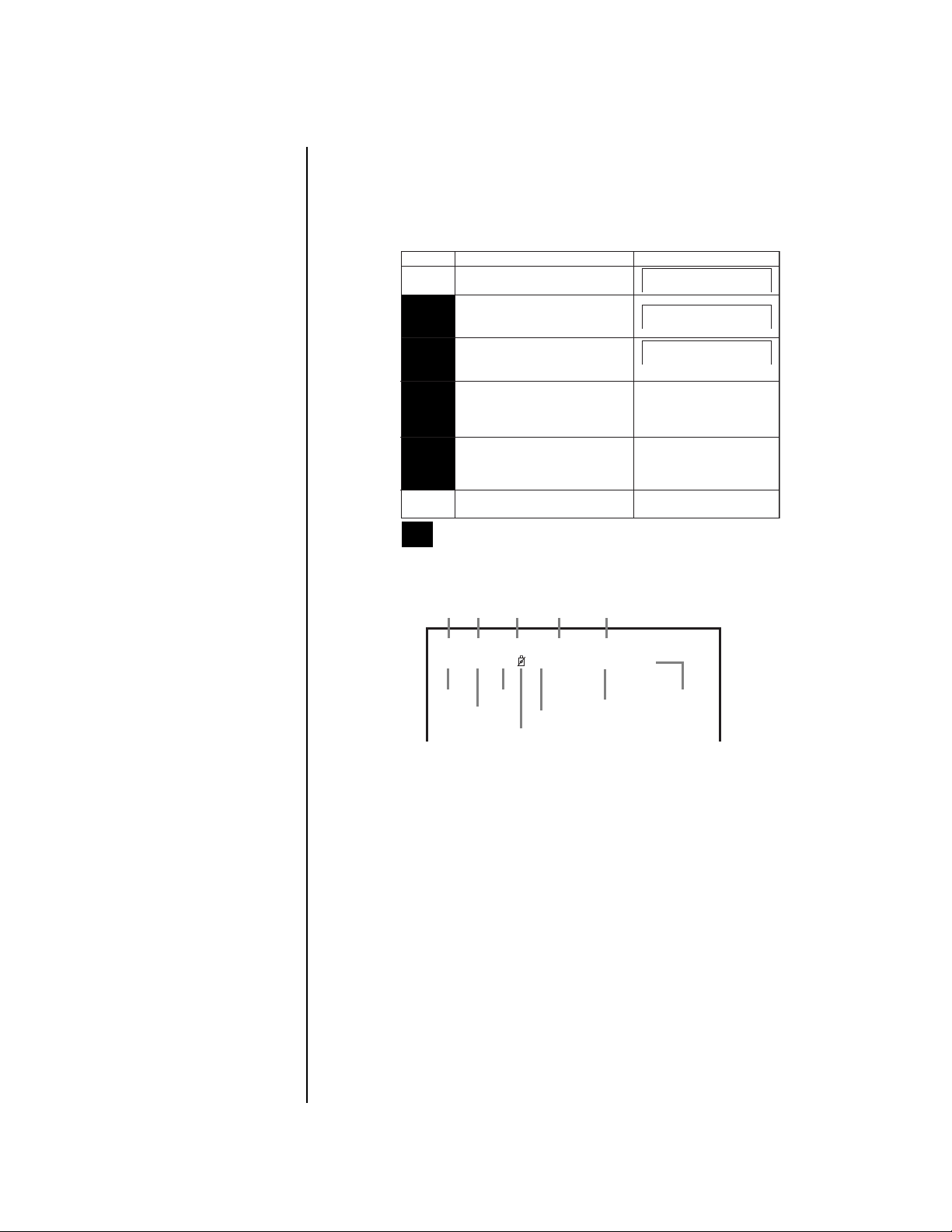
OPERATION
Press the POWER button on the front of the recorder to turn on the unit. Video from all nine
cameras appears on the monitor.
The time and date display may appear on the screen, depending on the setting of the Display Mode in the Time Date Display menu (refer to
ming
section). The different types of displays are shown below.
Time and Date Display
in the
Program-
Display Mode
Date, present time, and camera
1
number
Date, day of the week, present time,
recording interval, and camera
2
number
Date, day of the week, present time,
Recording interval, recording capacity
3
of HDD, and camera number
No indication
(When alarm signal is input, date, day of
4
the week, present time, and recording
interval will be displayed.)
No indication
(When warning signal is received,
5
warning indicator will be displayed.)
No indication
6
Display modes 2 to 5 are only available when single screen is displayed or
CH. TITLE is set to NONE in the MPX Display menu.
Display Sample
06-09-2000 11:39:10 C1
06-09-2000 FRI
11:39:10 12.5F C1
06-09-2000 FRI
11:39:10 12.5F 99C1%
01135
Below is a description of the time and date display when the display mode is set to 3.
Day of
Month
Date
the week Alarm recording number
Year
01 - 01 - 2000 SAT A0001
00 : 00 : 00 15F 50% C1
Time
Second
Minute
Non-operation camera mark
Recorded capacity of the Hard Disk
Recording interval
Camera number
The camera number does not appear if CH. TITLE is set to NONE in the MPX Display
menu.
The alarm recording number is displayed during alarm recording.
If you select a camera that is not programmed to be recorded, an icon appears showing a
camera with a line through it. Cameras are programmed in the Define Group Setting menu
(refer to
Record
in the
Programming
section).
The amount of space used in the hard drive is displayed during recording. When recording
is stopped, this figure is not displayed. (It remains displayed during pause.) When recording
is started again, this figure reappears after a few moments. The % symbol will flash when
the designated amount of space remaining on the storage medium has been reached (refer
to
Capacity Remaining
in the
Programming
section). The % symbol will flash only when one
camera is displayed on the monitor, not when multiple cameras are being shown.
The recorder can display dates from January 1, 2000 to December 31, 2030. It also has a
built-in function to calculate leap years automatically. After December 31, 2030, the date indicator will return to 2000.
The on-screen clock can be reset to the nearest hour by applying a signal to the CLOCK
ADJ terminal. For example, if the current time is 11:29:59, it will be reset to 11:00:00, and if
the current time is 11:30:00, it will be reset to 12:00:00.
Pelco Manual C681M-D (2/02) 57
Page 59

VIEWING CAMERAS
NOTE:
You cannot operate the CAMERA buttons when a menu is displayed on the
screen. The buttons do not work when the recorder is accessing a peripheral
recording device or the ARCHIVE, COPY, or PLAY button is flashing.
Press the CAMERA buttons (1-9) buttons to view images from cameras connected to CAMERA IN terminals at the rear of the recorder. If there is no video from a camera, or no camera is connected, the screen is blue. If the camera is not programmed for recording, the
non-operational camera icon appears on the screen (display modes 1-3). Cameras are programmed in the Define Group Setting menu (refer to
You can still view the picture from the camera even it is not programmed to be recorded.
SPLIT/SEQUENCE BUTTON
NOTE:
on the screen. The button does not work when the recorder is accessing a peripheral
recording device or the ARCHIVE, COPY, or PLAY button is flashing.
By pressing the SPLIT/SEQUENCE button, you can switch the display mode as follows:
DX3009 Models DX3016 Models
Nine cameras Sixteen cameras
Four cameras (group A) Nine cameras (group A)
Four cameras (group B) Nine cameras (group B)
Four cameras (group C) Four cameras (group A)
Single-camera sequencing* Four cameras (group B)
Four-camera group sequencing* Four cameras (group C)
You cannot operate the SPLIT/SEQUENCE button when a menu is displayed
Recording
Four cameras (group D)
Single-camera sequencing*
Four-camera group sequencing*
Nine-camera group sequencing*
in the
Programming
section).
* The SPLIT/SEQUENCE button lights.
The refresh cycle of camera images becomes longer as the number of cameras increases.
Smoother images can be viewed when cameras that are not needed are removed from the
cameras designated in the Define Group Setting menus (refer to
the
Programming
Images are displayed in real time during single-camera display.
Pressing the SPLIT/SEQUENCE button during playback switches the split display options
as follows:
DX3009 Models DX3016 Models
Nine cameras Sixteen cameras
Four cameras (group A) Nine cameras (group A)
Four cameras (group B) Nine cameras (group B)
Four cameras (group C) Four cameras (group A)
You can view any picture in actual screen size by pressing the camera number button.
You can go back to the previous split display by pressing the SPLIT/SEQUENCE button again.
If camera numbers are shown on the screen during sequencing of groups of four or nine
cameras, “-” appears instead of the camera number if the camera’s operation has been
turned off in the Define Group setting in the Normal Rec Setting menu.
If camera numbers are part of the time and date display, the display is shown only in Mode 1
when more than one camera appears on the screen.
section).
Four cameras (group B)
Four cameras (group C)
Four cameras (group D)
Alarms
and
Recording
in
If a camera is not programmed for recording, the screen for that camera is black. If there is
no video (camera is not turned on or is not connected), the screen for that camera is blue.
58 Pelco Manual C681M-D (2/02)
Page 60

ZOOM BUTTONS
NOTE:
screen. The buttons do not work when the recorder is accessing a peripheral
recording device or the ARCHIVE, COPY, or PLAY button is flashing.
1. Display the Zoom Pointer (X) by pressing the ZOOM button.
2. Move the pointer to the desired position by pressing the camera number buttons 6 to 9.
3. Press the 4 button once to make the picture twice as large as the original picture size.
4. After enlarging the picture, press the 5 button to reduce it.
You cannot operate the ZOOM buttons when a menu is displayed on the
The picture will be enlarged/reduced from the center of the pointer.
Press the button a second time to make the picture four times as large. The zoom
ratio appears in the top left-hand corner of the screen. As the zoom function is digital,
details of the image appear pixelized when enlarged. After enlarging the picture, you
can move the whole picture by pressing the 6-9 buttons.
The zoom pointer’s position does not change when the display screen changes or
when power is turned off. This is convenient for situations where the desired viewing
areas, such as a counter or cash register, are determined in advance. In addition,
the zoom pointer can be used during playback of recorded images.
When playing back images from multiple cameras on a single screen, if the zoom
control is used during the pause mode, there is a possibility that a black screen will
be displayed. In this case, the desired enlarged image can be obtained by moving
through frames using the JOG dial.
The zoom function is deactivated if the ALARM IN terminal is triggered.
REMOTE VIEWING
Camera images can be viewed from a remote site using a PelcoNet Transmission System.
To view images remotely, refer to separate documentation that accompanies PelcoNet.
RECORDING
BASIC RECORDING
1. Press a camera number button and verify that there is video.
2. Press the REC button. The REC button lights and recording starts.
If you press the PAUSE button during recording, recording will pause. To resume recording, press the PAUSE button again. (The PAUSE button only works when MAIN is
selected as a playback device. Press the PLAY DEVICE button to select MAIN.)
A warning appears during recording if there is no input signal from the selected camera channel (refer to the
menu for those cameras with no input (refer to
ming
during split-screen viewing when an image from another screen will appear in a channel without an input signal.
The HDD FULL setting determines the operation of the recorder when the hard disk is full.
Refer to
If multiple recorders are connected in series, when the storage capacity of the one
unit’s memory reaches a pre-specified level, the next unit begins recording. Through
this exchange, recording continues uninterrupted.
Warnings
section). If the unit is operated without this “ - ” setting, there may be occasions
HDD (Hard Disk Drive) Repeat Recording
section.) In addition, select “ - ” in the Define Group
Record, Define Group
in the
Programming
in the
section.
Program-
3. Press the STOP button to stop recording. The REC button light goes out.
Pelco Manual C681M-D (2/02) 59
Page 61
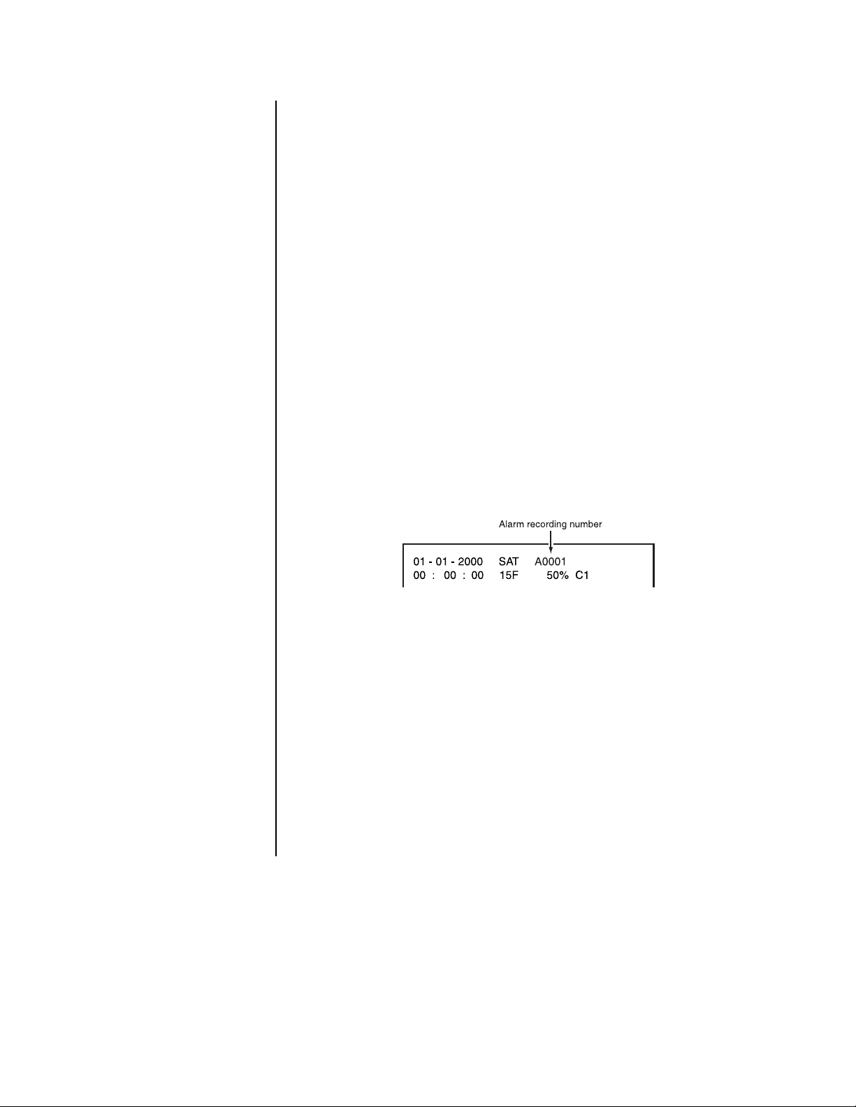
ALARM RECORDING
Alarm recording commences upon either of the following conditions:
• An ALARM IN terminal is triggered by an alarm sensor
•A camera detects motion
When there is an alarm:
Alarms
in the
1) The recorder switches to its preset recording intervals. Refer to
gramming
2) An index signal is automatically stored in memory when alarm recording begins.
Refer to the
3) If the unit receives a new alarm signal while in the alarm recording mode, the unit
completes the alarm recording session initiated by the new signal.
4) If the unit receives an alarm signal at an ALARM IN terminal while settings are being
made on the on-screen menus, the unit exits the menu screen and begins alarm recording.
5) The unit stores a data entry in an Alarm List of the time it receives the alarm signal.
Refer to the
6) Regardless of the display mode, camera number buttons flash for those cameras
making alarm recordings. The Alarm Recording indicator flashes on and off during
alarm recording and stays on at the completion of alarm recording. If the DISPLAY
MODE is set for values other than 5 or 6, an Alarm Recording number will automatically appear on-screen while the unit is running in alarm recording mode. The maximum Alarm Recording number is 9999.
section for alarm settings.
Playback
Playback
section for reviewing alarm recordings using the index search.
section for reviewing images from the Alarm List.
Pro-
At the end of alarm recording, the unit returns to the same recording intervals that
were in effect before the alarm recording.
When in the alarm recording mode, the unit records for the entire alarm recording duration even if the end-time specified in a timer program has been exceeded. Alarm recording also continues as long as motion is detected within the active area established
for motion detection. When motion stops, alarm recording continues for the time set in
the A-REC DURATION setting.
There may be cases when the recorder’s built-in motion detection function does
not operate properly due to the condition of the input video signal or other factors.
There may be such operation errors when the recorder is connected to a system
that uses the recorder’s detection function to send a warning signal.
If the recorder is programmed for pre-alarm recording, pre-alarm recordings are made
of all cameras since it is not known which camera will have an alarm. After an ALARM
IN terminal is triggered, however, only those cameras designated in the RECORD
ALARM setting will make alarm recordings. This means that during playback the number of cameras displayed may differ for pre-alarm and post-alarm recording.
60 Pelco Manual C681M-D (2/02)
Page 62

TIMER RECORDING
1. Select the timer program (P1, P2, or P3) that you want to use for recording. Refer to
Timer Recording
2. Press the TIMER REC button. The TIMER REC indicator illuminates. If the current time
is covered by a program, the unit begins recording immediately. If the current time is
not covered by a program, the unit turns the power off and goes into standby mode.
3. To stop timer recording, press the TIMER REC button once more.
in the
Programming
section.
NOTE:
section on
Also refer to the
Playback on
Another Device
NOTE:
If PRE A-REC has been set to SHORT, MEDIUM, or LONG in the A-Rec/M-Det
Setting Menu, the recorder will use the alarm recording settings to make timer
recordings, even though there is no alarm signal when recording starts.
PLAYBACK
BASIC PLAYBACK
1. Turn on the power of the connected peripheral recording device, if any, and then turn
on this recorder.
2. Press the PLAY DEVICE button on the front panel to select the playback device.
The indicator of the selected device illuminates. (The indicator will not light when a
.
peripheral recording device is not connected.)
3. Press the PLAY button.
NOTE:
When playing back from a DDS device, there will be a few minutes delay
in playback and eject, depending on the condition of the recording.
The oldest recording on the hard disk is played back when you press the PLAY button
for the first time after the power is turned on
for the first time after you stop recording
The newest recording on the hard disk is played back (in the reverse direction) when
you press the REV PLAY button
for the first time after the power is turned on
for the first time after you stop recording
After the first time, subsequent pressing of the PLAY or REV PLAY buttons will resume
playback from the point where it was stopped.
When recording more than one camera, the playback interval per camera will be the
frames per second multiplied by the number of cameras. A recording interval of 15
frames equals one second.
• Single camera: The screen changes frame-by-frame at a rate equal to the recording interval multiplied by the number of cameras used in the recording.
• Four cameras: Each camera changes frame-by-frame at a rate equal to the recording interval multiplied by the number of cameras used in the recording. The display
shifts to still-frame mode during playback from a camera that is not indicated.
• Nine and sixteen cameras: Each camera changes frame-by-frame at the recorded rate. The display shifts to still-frame mode during playback from a camera
that is not indicated.
Playback will stop automatically at the end of the hard disk (if extra hard disk drives
are installed, playback will stop at the end of the hard disk drive with the highest ID
number) or the end of the recorded part when the HDD PB REPEAT field in the Initial
Set Up menu is set to OFF. The recorded data is played back repeatedly when the
HDD PB RPEAT field is set to REPEAT. Refer to
back
in the
Programming
4. Press the STOP button to stop playback.
5. Press the EJECT button to eject the medium from a copy or archive device.
section.
Hard Disk Drive (HDD) Repeat Pay-
Pelco Manual C681M-D (2/02) 61
Page 63

FRAME-BY-FRAME (STILL FRAME) PLAYBACK
1. Press the PAUSE button during playback. The unit shifts into still-frame mode.
2. If the screen shows more than one camera, you can view a full-screen view of a single
camera by pressing the CAMERA button for that camera.
3. Turn the JOG dial in either direction during still-frame playback.
Turn the JOG dial one stop to the right to move forward one frame and one stop to the
left to move back one frame. Continue turning the JOG dial to the right for forward
playback of consecutive frames and to the left for reverse playback of consecutive
frames. Stop turning the dial for still-frame viewing.
The PLAY button lights when moving in the forward direction, and the REV PLAY button lights when moving in the reverse direction.
If you switch directions, the first stop reverses the direction, as indicated by the lights
changing on the PLAY and REV PLAY buttons, but the video does not move. When
you turn the JOG dial to the next stop, the video moves forward or backward one
frame.
4. Press the PAUSE button again to resume playback in the forward or reverse direction,
depending on whether the PLAY or REV PLAY button is lit. Or, press the PLAY or REV
PLAY button to exit the pause mode and resume playback in the desired direction.
PAUSE PLAYBACK
1. Press the PAUSE button to pause playback.
2. Press the PAUSE button again to resume playback.
REVERSE PLAYBACK
Press the REV PLAY button when the unit is not in operation. The unit begins reverse playback.
On the first reverse playback after the power switch is turned on or after recording, the unit
starts by displaying the last recorded image.
ADJUSTING PLAYBACK SPEED
The SHUTTLE ring can be used to adjust the playback speed. Playback speed will vary according to how far the SHUTTLE ring is turned.
01139
Regular Playback Mode
1. Turn the SHUTTLE ring to the desired playback speed while the recorder is in playback or reverse playback.
When playing back images recorded at different recording intervals, there may be rare
occasions when the playback speed differs from the original recording rate.
2. The unit shifts to regular playback mode when the SHUTTLE ring is returned to the
center position.
62 Pelco Manual C681M-D (2/02)
Page 64

Still-Frame Playback Mode
1. Press the PAUSE button while the recorder is in playback or reverse playback. The
unit shifts to still-frame playback mode.
2. Turn the SHUTTLE ring to the desired playback speed.
3. The unit shifts to still-frame playback mode when the SHUTTLE ring is returned to the
center position.
Shuttle Hold
Pressing the PAUSE button during playback (or reverse playback) shifts the recorder into stillframe mode. Rotate the SHUTTLE ring to the desired search speed, and then press the
PAUSE button while holding the SHUTTLE ring at the selected search speed. Search speed
will be maintained even when the SHUTTLE ring is returned to its original position.
CHANGING PLAYBACK INTERVAL
When the PLAY or REV PLAY button is pressed when the unit is not in operation, playback
occurs at the same intervals as the recording intervals. Playback intervals can be changed,
however, when the PLAY or REV PLAY button is pressed while the unit is in playback or reverse playback operation. This is a convenient function for slow viewing of recordings with
fast movement or fast playback of images captured at long recording intervals.
Playback or reverse playback intervals speed up when the PLAY button is pressed.
Playback or reverse playback intervals slow down when the REV PLAY button is pressed.
01-01-2000 SAT A0001
00 : 00 : 00 15F 30%
SE
If the time and date display is in Mode 2 or 3 (refer to
gramming
followed by an F) in the display.
An audio recording cannot be played when the playback interval has been altered, even if
the playback interval is returned to its original rate. To play back an audio recording, stop
playback and restart it at the original rate.
section), you can verify the change by observing the playback interval (number
Time and Date Display
in the
Pro-
FAST FORWARD/REWIND
When the SHUTTLE ring is turned clockwise or counterclockwise for more than one second
when the recorder is not recording, the unit shifts into high-speed fast-forward or highspeed rewind mode, and an indicator appears at the bottom left of the monitor. “S” denotes
the start point of the data stored in the hard disk and “E” denotes the end point. The vertical
line marks the current position.
Press the STOP button to stop the fast forward or rewind operation.
SEARCHING
Time and Date Search
1. Press the SEARCH button to display the Search Selection menu.
2. Make sure the cursor is next to SELECTION CAMERA NO., and then turn the
SHUTTLE ring to the right. The option starts flashing.
3. Turn the JOG dial to select the option, and then turn the SHUTTLE ring to the right.
The option stops flashing.
Turning the JOG dial switches the options as follows:
DX3009 Models – ALL, 1, 2, 3, 4, 5, 6, 7, 8, 9
DX3016 Models – ALL, 1, 2, 3, 4, 5, 6, 7, 8, 9, 10, 11, 12, 13, 14, 15, 16
Pelco Manual C681M-D (2/02) 63
Page 65

4. Turn the JOG dial to move the cursor beside TIME DATE SEARCH, and then turn the
SHUTTLE ring to the right. The Time Date Search menu appears and the month number starts flashing.
NOTE:
If the PRE A-REC field in the A-Rec/M-Det Setting menu has been set to
SHORT, MEDIUM, or LONG, the menu cannot be accessed.
To exit the Time Date Search menu without activating the search, press the SEARCH
button on the front of the unit.
5. Turn the JOG dial to set the month. Turn the SHUTTLE ring to the right. The next item
starts flashing.
6. Repeat step 3 to set the date, year, hour, 10-minutes digit, minute digit, 10-seconds
digit, and second digit . The option OFF starts flashing.
7. Turn the JOG dial to select ON
8. Turn the SHUTTLE ring to the right. The time date search starts and pauses the playback display at the specified time point (or the nearest point from the specified time).
The searched image appears in a 9-camera display (DX3009 models) or 16-camera
display (DX3016 models) if ALL was selected or on a single screen if an individual
camera was selected. The PLAY and PAUSE buttons light.
If there is no recording or no data that is recorded on the date you have set, the time-date
search will not be activated and the month number will start flashing again.
If there is no data that is recorded at the time you have set, the image that is recorded
at the nearest time from the time you have set will be displayed on the paused screen.
The time date search function may not work correctly depending on the condition of
the recording.
To change the 9-camera display (DX3009 models) or 16-camera display (DX3016
models) to a single camera, press the CAMERA number button on the front of the
recorder.
.
9. Press the PLAY or PAUSE button to play back the searched image.
10. Press the STOP button to stop playback and exit the search function.
Index Search
During alarm recording, an index signal is automatically written onto the hard disk. Index
search is a process of retrieving still frames using their associated index signal.
The index count can be set, as desired, up to 99.
1. Press the SEARCH button to display the Search Selection menu.
2. Make sure the cursor is next to SELECTION CAMERA NO., and then turn the
SHUTTLE ring to the right. The option starts flashing.
3. Turn the JOG dial to select the option, and then turn the SHUTTLE ring to the right.
The option stops flashing.
Turning the JOG dial switches the options as follows:
DX3009 Models – ALL, 1, 2, 3, 4, 5, 6, 7, 8, 9
DX3016 Models – ALL, 1, 2, 3, 4, 5, 6, 7, 8, 9, 10, 11, 12, 13, 14, 15, 16
4. Turn the JOG dial to move the cursor to INDEX SEARCH, and then turn the
SHUTTLE ring to the right. The Index Search menu appears.
NOTE:
SHORT, MEDIUM, or LONG, the menu cannot be accessed.
5. Turn the JOG dial to display the desired index count.
If the PRE A-REC field in the A-Rec/M-Det Setting menu has been set to
64 Pelco Manual C681M-D (2/02)
Page 66

6. Turn the SHUTTLE ring in the desired search direction.
The present position in the diagram below represents the point of playback or stopped
playback. To search for an index with a “+”, turn the SHUTTLE ring to the right to
search forward. To search for an index with a “-”, turn the SHUTTLE ring to the left to
search backward.
A•REC: Alarm Recording
-15 -1-2 +1 +15+2
A•REC A•REC A•REC A•REC A•REC A•REC
Present position
Beginning of playback device
The index search begins, and images appear in a 9-camera display (DX3009 models)
or 16-camera display (DX3016 models) if ALL was selected or on a single screen if an
individual camera was selected. The PLAY and PAUSE buttons light.
NOTE:
When using DDS tape, index searches can be done in the forward
End of playback device
direction only.
7. Press the SEARCH button to clear the Search menu from the screen.
8. To change the 9-camera display (DX3009 models) or 16-camera display (DX3016
models) to a single-camera display, press the CAMERA number button on the front of
the recorder. The display for the single camera appears.
9. Press the PLAY or PAUSE button to play back the searched image.
10. Press the STOP button to stop playback and exit the search function.
Skip Search
Skip search is a process in which the unit automatically searches for an index signal, and then
retrieves the visuals associated with that index and plays back the images for five seconds each.
1. Press the SEARCH button to display the Search Selection menu.
2. Make sure the cursor is next to SELECTION CAMERA NO., and then turn the
SHUTTLE ring to the right. The option starts flashing.
3. Turn the JOG dial to select the option, and then turn the SHUTTLE ring to the right.
The option stops flashing.
Turning the JOG dial switches the options as follows:
DX3009 Models – ALL, 1, 2, 3, 4, 5, 6, 7, 8, 9
DX3016 Models – ALL, 1, 2, 3, 4, 5, 6, 7, 8, 9, 10, 11, 12, 13, 14, 15, 16
4. Turn the JOG dial to move the cursor to SKIP SEARCH, and then turn the SHUTTLE
ring to the right. The Skip Search menu appears.
NOTE:
If the PRE A-REC field in the A-Rec/M-Det Setting menu has been set to
SHORT, MEDIUM, or LONG,
5. Turn the SHUTTLE ring in desired direction (forward search to the right and reverse to
the left). The unit begins the index search and plays back the images associated with
the index for five seconds each.
Images appear in a 9-camera display (DX3009 models) or 16-camera display
(DX3016 models) if ALL was selected or on a single screen if an individual camera
was selected.
The image cannot be changed from a 9-camera display (DX3009 models) or 16-camera
display (DX3016 models) to a single-camera display.
Depending on the recording condition of the index signal, there might be occasions
when skip search cannot be performed.
6. Press the STOP button to stop searching.
the menu cannot be accessed.
Pelco Manual C681M-D (2/02) 65
Page 67

Alarm List Search
The Alarm List search retrieves alarm video at the time an alarm occurred. It does not retrieve pre-alarm recording if the pre-alarm recording option was turned on (PRE A-REC
field in the A-Rec/M-Det Setting menu).
Up to 500 alarm times (DX3009 models) or 800 alarm times (DX3016 models) can be stored
in the alarm list. After the 500th time (DX3009 models) or 801st time (DX3016 models), the
first alarm time is erased and the 501st (or 801st) alarm time is added to the list.
1. Press the SEARCH button to display the Search Selection menu.
2. Make sure the cursor is next to SELECTION CAMERA NO., and then turn the
SHUTTLE ring to the right. The option starts flashing.
3. Turn the JOG dial to select the option, and then turn the SHUTTLE ring to the right.
The option stops flashing.
Turning the JOG dial switches the options as follows:
DX3009 Models – ALL, 1, 2, 3, 4, 5, 6, 7, 8, 9
DX3016 Models – ALL, 1, 2, 3, 4, 5, 6, 7, 8, 9, 10, 11, 12, 13, 14, 15, 16
4. Turn the JOG dial to move the cursor to ALARM LIST SEARCH, and then turn the
SHUTTLE ring to the right to display the Alarm List Search menu.
5. Turn the JOG dial until the cursor is at the desired alarm list number. When the cursor
reaches either the top or the bottom of the list, the Alarm List Search menu scrolls to
the next page. To move through the pages, place the cursor over “No.”, and then turn
the SHUTTLE ring.
6. Turn the SHUTTLE ring to the right. The unit begins the alarm list search and retrieves
the image associated with the selected time.
NOTE:
If the PRE A-REC field in the A-Rec/M-Det Setting menu has been set to
SHORT, MEDIUM, or LONG, the search cannot be done.
Images appear in a 9-camera display (DX3009 models) or 16-camera display
(DX3016 models) if ALL was selected or on a single screen if an individual camera
was selected. The PLAY and PAUSE buttons light.
7. Press the SEARCH button to clear the Alarm List from the screen.
8. To change the 9-camera display (DX3009 models) or 16-camera display (DX3016
models) to a single-camera display, press the CAMERA number button on the front of
the recorder. The display for the single camera appears.
9. Press the PLAY or PAUSE button to play back the searched image.
10. Press the STOP button to stop playback and exit the search function.
Jump to Starting Point
Select this option to play back the oldest recorded data.
1. Press the SEARCH button to display the Search Selection menu.
2. Turn the JOG dial to move the cursor to JUMP TO START POINT, and then turn the
SHUTTLE ring to the right. The Jump to Start Point screen appears.
3. Turn the SHUTTLE ring to the right. The recorder displays the oldest recordings on a
9-camera screen (DX3009 models) or 16-camera screen (DX3016 models). The PLAY
and PAUSE buttons light.
4. To change the 9-camera display (DX3009 models) or 16-camera display (DX3016
models) to a single-camera display, press the CAMERA number button on the front of
the recorder. The display for the single camera appears.
66 Pelco Manual C681M-D (2/02)
Page 68

5. Press the PLAY or PAUSE button to play back the searched image.
6. Press the STOP button to stop playback and exit the search function.
PLAYBACK ON ANOTHER DEVICE
Data recorded on an external copying or archiving device can be played back on a personal computer or laptop computer.
1. Make sure the PC or laptop computer has the DX3016RX Remote Viewing Software
installed on it. The software was supplied with your DX3000 Series recorder or can be
downloaded from Pelco’s website at Pelco.com.
2. Connect the external copying or recording device to the PC or laptop computer.
BACKING UP DATA
The recorder can back up data which is recorded on the hard disk drive. You can back up
data previously recorded data at the same time the DVR is recording new data (refer to the
section on
There are two ways to make copies:
Using the ARCHIVE button
Using the COPY button
Simultaneous Recording and Backup
USING THE ARCHIVE BUTTON
NOTE:
assigned to SCSI ID number 4.
If you use the ARCHIVE button, the peripheral recording device must be
).
Start Copying
Press the ARCHIVE button. The button starts blinking. While the light is blinking, the
archiving process is being set up. This may take several minutes. When the light remains
on, the backup is in progress.
When the ARCHIVE button is pressed, the recorder makes backups after the point indicated by the Archive Pointer. If the Archive Overwrite setting is OFF, the backup process
will not overwrite data already recorded on the storage medium. If ON, data previously recorded on the storage medium will be overwritten and erased. Refer to
in the
Programming
The position of the Archive Pointer will not be erased when the unit’s main power switch is
turned off. To reset the position of the pointer, refer to
gramming
section.
section.
Archive Pointer Reset
Archive, Overwrite
in the
Pro-
Stop Copying
Press the ARCHIVE button. The button blinks while the archiving process is halted. If the
Auto Eject setting is ON, the medium is automatically ejected at the end of the process.
The Archive Pointer is repositioned to where operation was stopped, and the next backup
recording will begin at this point.
Timer Backup
Timer backup is a method for using the timer to perform archive backup. The timer can be
used to archive data in the main hard disk drive that has not yet been backed up. The unit
can archive data even if it is currently in the process of timer recording.
Refer to
setting, select ARC.
The recorder makes backups on the archive device after the point indicated by the Archive
Pointer if the ARCHIVE OVERWRITE setting is OFF. If ON, data previously recorded on the
storage medium will be overwritten and erased. Refer to
ming
Timer Recording
section.
in the
Programming
section to program the recorder. In the Mode
Archive, Overwrite
in the
Program-
Pelco Manual C681M-D (2/02) 67
Page 69

Auto-Eject at the Completion of Backup
The archive medium will be automatically ejected under the following conditions:
When the archive medium becomes full during archive backup. Refer to
Programming
When the archive medium becomes full during timer backup. Refer to
gramming
When the ARCHIVE button is pressed again, after operation was started with the ARCHIVE
button.
When a recording malfunction, medium error, or system error occurs during backup operation.
section.
section.
Auto Eject
Auto Eject
in the
in the
Pro-
USING THE COPY BUTTON
NOTE:
If you use the COPY button, the peripheral recording device must be assigned
to SCSI ID number 5.
1. Make sure that the peripheral recording device is connected and set correctly.
2. Turn on the power of the peripheral recording device.
3. Turn on the power of the recorder.
4. Insert a copying medium into the archive device or copy device.
5. Press the COPY button. The Copy Selection menu appears.
6. Make sure that the cursor is next to COPY DIRECTION, and then turn the SHUTTLE
ring to the right. The option starts flashing.
7. Use the JOG dial to choose copy direction (HDD to COPY), and then turn the
SHUTTLE ring to the right. The option stops flashing.
8. Turn the JOG dial to move the cursor to OVERWRITE, and then turn the SHUTTLE
ring to the right. The option starts flashing.
9. Turn the JOG dial to select ON or OFF, and then turn the SHUTTLE ring to the right.
The option stops flashing.
ON: Copying starts at beginning of the medium, overwriting previously recorded data.
OFF: Copying starts at the end of the recorded part of the medium.
10. Turn the JOG dial to move the cursor next to TRANSFER PERIOD, and then turn the
SHUTTLE ring to the right. The option starts flashing.
11.Turn the JOG dial to select MAN or S/E, and then turn the SHUTTLE ring to the right.
The option stops flashing.
MAN: Set the starting and ending times for copying in the next step.
S/E: Copy all data from the device which is recognized as a device to copy from.
12. Set the starting and ending times.
If S/E was selected in the previous step, the starting and ending times of the data re-
corded on the hard disk are displayed. There may be instances where it takes time for
the peripheral device to collect the copy starting and ending times from the main unit.
When the times are displayed, press the COPY button to enter the copy range automatically. This does not mean, however, that the copy function has been started.
If MAN was selected, the recorder will execute the copy function at a range slightly
larger than the starting and ending settings.
a. Turn the JOG dial to move the cursor to the start time.
68 Pelco Manual C681M-D (2/02)
Page 70

b. Use the JOG dial and SHUTTLE ring to set the month, date, year, hour, minute,
and second of the starting time.
c. Turn the JOG dial to move the cursor to the stop time.
d. Use the JOG dial and SHUTTLE ring to set the month, date, year, hour, minutes,
and second of the ending time.
If the copy range exceeds the amount of available storage space in the copy medium,
the recorder issues a size error warning during the copy operation. In this case, either
reset the copy range or replace the copy medium. Limits to the copy range can be
established by first selecting S/E to find the starting and ending times; then the manual
settings can be made.
13. Turn the JOG dial to move the cursor beside EXECUTE, and then turn the SHUTTLE
ring to the right. The option OFF starts flashing.
14. Turn the JOG dial to select ON.
15. Turn the SHUTTLE ring to the right to start copying.
Still-Frame Playback Copy Mode
DX3009 Models
By pressing the PAUSE button and, while the unit is in still-frame playback mode, setting
the Transfer Period to MAN in the Copy Selection menu, the unit copies 1 MB of data from
the time when the PAUSE button is pressed.
DX3016 Models
Press the PAUSE button, and then press the COPY button. One megabyte of data is copied from the time the PAUSE button is pressed.
SIMULTANEOUS RECORDING AND BACKUP
Backups of previously recorded data can be made at the same time the DVR is recording
new data, but the following restrictions apply.
1. Cancelling copy operation
If you are doing a backup at the same time the DVR is recording and you want to stop
the backup operation, press the WARNING RESET button.
2. Selecting recording interval for simultaneous backup
The recording interval for simultaneous backup of recorded data is determined by the
data-writing speed of the connected device. For reference, the following chart provides
a list of interval modes that can be selected when the unit is used in conjunction with a
Hewlett-Packard C1556A drive (DDS3). (The same modes apply when the main hard
disk drive has been expanded.)
Field/sec.
IMAGE QUALITY
SUPERIOR
HIGH
MEDIUM
STANDARD
BASIC
30F 15F 7.5F 5F
Nonselectable
:Simultaneous backup is possible without audio
:Simultaneous backup is possible with audio
Pelco Manual C681M-D (2/02) 69
Page 71

3. Precautions when designating simultaneous timer backup
The backup program, which can be designated as an individual operation, can also be
designated with the record and power programs. The following items apply when designating these multiple program modes.
There may be restrictions imposed by the other recording devices. It is recommended
that adequate program checks are run before actual operation.
Observe the following precautions when connecting devices requiring time to halt
startup (for example, archive devices, tape recording devices etc.)
• Using the backup setting’s designated time plus five minutes (the halt startup
time of the peripheral recording devices) as a gauge, set the unit so that modes
do not change. (Refer to illustration 1.)
• Even when only designating the backup mode, add one minute or more to the
backup operation time, and set other programs to start and stop. (Refer to Illustration 2.)
RECORDING A-7.5F
(or POWER setting)
Backup
Longer than 5 minutes
Illustration 1:
Correct setting
RECORDING A-7.5F
(or POWER setting)
Longer than 1 minutes
Illustration 2
RESTORING DATA FROM A BACKUP DEVICE
The recorder can restore recorded data to the hard disk from an archive or copy device.
Follow the steps in the section on
In step 7, set the Copy Direction to COPY –> HDD. In step 8, ON is the only setting available for OVERWRITE. During the restoration process, image data currently stored on the
unit’s hard disk is overwritten.
Using the COPY Button
Backup
Longer than 1 minutes
in the
Backing up Data
RECORDING A-7.5F
(or POWER setting)
section.
70 Pelco Manual C681M-D (2/02)
Page 72

INFORMATION
ELAPSED TIME DISPLAY
1. Press the INFO button. The Information menu appears. The elapsed time appears in
the lower part of the screen.
2. To exit the menu, press the INFO button again.
The elapsed time of main hard disk drive, archive device, and copy device are shown
on the screen. The elapsed time for the archive or copy devices will not be displayed
unless they are connected to the recorder.
The elapsed time of main hard disk drive is counted when the recorder’s power is
turned on.
The elapsed time of the peripheral device (ID4) is counted:
• When the ARCHIVE button illuminates or flashes
• When the PLAY or REV PLAY button illuminates or flashes when the archive de-
• While the ARCHIVE indicator illuminates or flashes when restoring the data from
The elapsed time of the peripheral device (ID5) is counted:
• When the PLAY or REV PLAY button illuminates or flashes when the copy device
• When the COPY indicator illuminates or flashes when copying the data from
vice is selected as a playback device using the PLAY DEVICE button
main hard disk drive to the archive device
is selected as a playback device using the PLAY DEVICE button
main HDD to the copy device
• When the COPY indicator illuminates or flashes when restoring the data from
main HDD to the copy device
The elapsed time of the archive device or copy device will not be reset even though
those devices are disconnected.
The elapsed time of archive device starts when the ARCHIVE button is pressed (when
pressed, the ARCHIVE button illuminates), even when there is no data on the main
hard disk drive, such as when the recorder is in the alarm standby mode.
The elapsed time may not be consistent with the normal time for wearing of parts.
The elapsed time is shown up to a maximum of 999999 hours.
POWER FAILURE LIST
If your system has had power failures, you can view the Power Failure list to see when they
occurred. Up to 50 power failure starting times are shown on the list. If there are more than
50 times, the last 50 starting times are shown.
1. Press the SET UP button to display the Menu Setting menu.
2. Turn the JOG dial to move the cursor to SERVICE, and then turn the SHUTTLE ring to
the right. The Service menu appears.
3. Turn the JOG dial to move the cursor next to POWER FAILURE, and then turn the
SHUTTLE ring to the right. The Power Failure list appears on the screen. The number
of times, the date, and the time when the power failure occurred are given on the list.
To reset the power failure start time, press the WARNING RESET button when the
Power Failure list is shown on the screen.
4. Press the SET UP button to exit the menu.
Pelco Manual C681M-D (2/02) 71
Page 73

RECORDED PERIOD
The recorded periods of the main hard disk drive, the archive device, and the copy device
are shown on the screen.
The archive device is displayed only when an archive device is connected to ID4.
The copy device is displayed only when a copy device is connected to ID5.
1. Press the INFO button. The Information menu appears.
2. Check that the cursor is next to RECORDED PERIOD, and then turn the SHUTTLE
ring to the right.
3. The message, “GET S/E INFORMATION. TURN THE SHUTTLE RING >> TO EXECUTE.” appears on the screen. Turn the SHUTTLE ring to the right. The Recorded
Period menu appears.
4. To exit the menu, press the INFO button again.
SCSI DEVICE(S) CONNECTED
The SCSI ID number of connected devices can be confirmed on the screen.
1. Press the INFO button. The Information menu appears.
2. Turn the JOG dial until the cursor is next to CONNECTED SCSI DEVICE, and then
turn the SHUTTLE ring to the right. The SCSI ID numbers appear on the screen.
ID0 to ID3 are allocated to the main hard disk drive. ID4 is allocated to the archive device, and ID5 is allocated to the copy device.
3. To exit the menu, press the INFO button again.
POWER FAILURE
The unit resumes recording after a power failure if the unit was recording prior to the power
failure. When running a timer recording, the unit restarts recording if a power failure ends
before the user-specified time frame. An “X” appears next to the time display following a
power outage; push the WARNING RESET button to remove the “X.”
If there is a power failure during recording, image quality may be partially degraded and
search functions may not operate normally.
The starting times of power failures are recorded when power is restored and can be confirmed later. (Starting times of power failures occurring during backup operation are not recorded.) Refer to
The unit is equipped with an internal power failure compensation circuit, and, after a full recharge of 48 or more hours, will preserve data and time settings for one month. Timer settings and menu settings will also be preserved. Time settings will not be precise, however,
if the circuit has been unplugged for a long period of time. If this situation continues, it is
recommended that current time settings be confirmed.
Recharging occurs automatically while the recorder is plugged into a 100-240 VAC power
source.
RESET
The following conditions occur when the RESET button located on the unit’s back panel is
pressed (using a ball-point pen or other object): the current time is erased, the system is
reset, and main power is turned off. Recorded data and menu settings are not erased.
Information, Power Failure List
in the
Operation
section.
72 Pelco Manual C681M-D (2/02)
Page 74
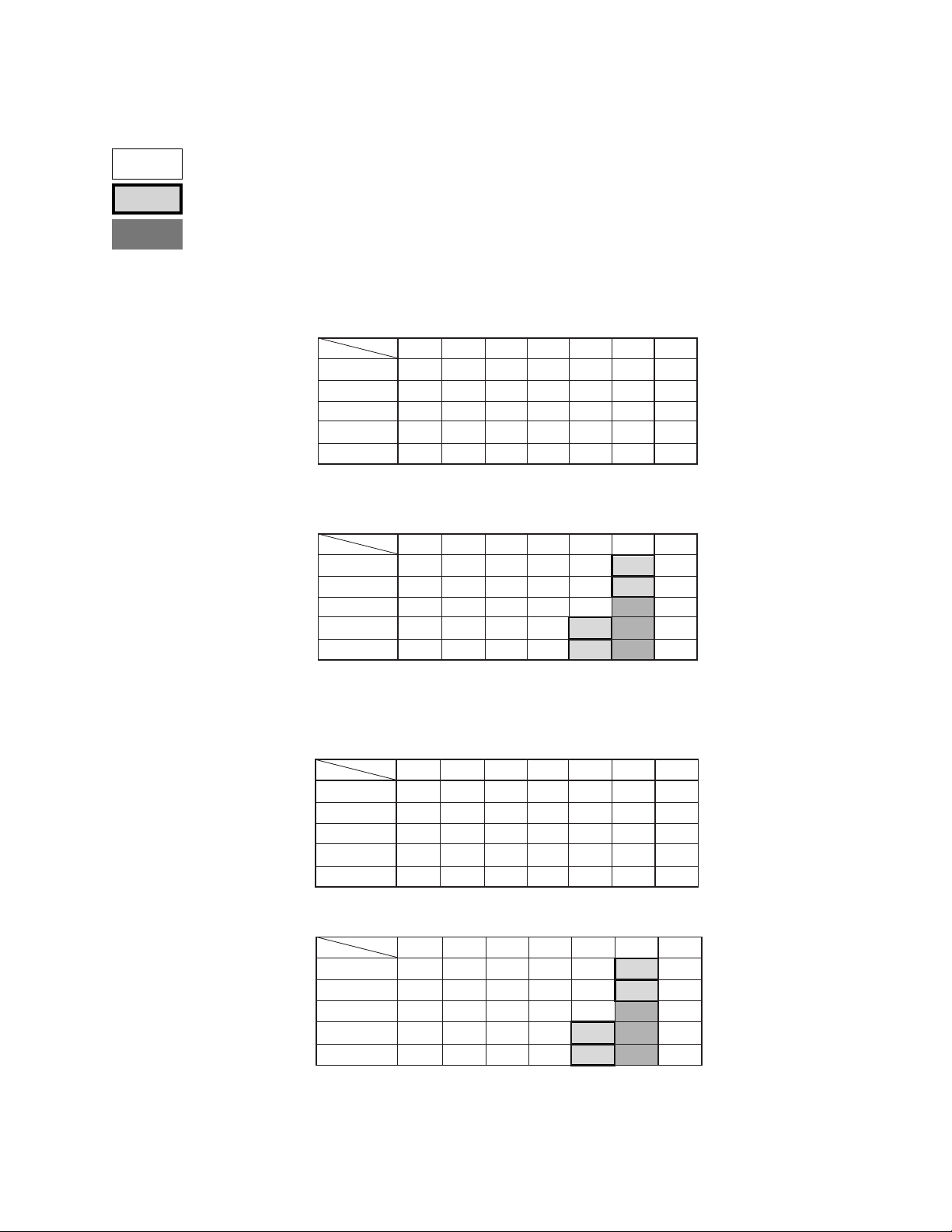
DX3009 RECORDING TIME TABLES
Audio recording possible. (12.8kHz sampling)
Audio recording possible, but with diminished quality. (8kHz sampling)
Audio recording not possible.
■ Audio recording time table
Approximate recording time (if recording is made with internal 30 GB HDD)
♦ Without Audio recording
♦ Audio recording
Field/sec.
IMAGE QUALITY
SUPERIOR
HIGH
MEDIUM
STANDARD
BASIC
Field/sec.
IMAGE QUALITY
SUPERIOR
HIGH
MEDIUM
STANDARD
BASIC
30F 15F 7.5F 5F 3F 1F
6h10min
9h40min
4h50min
7h10min
12h
19h
1D14h
13h
1D 3h
2D 7h
18h
1D12h
22h
1D21h
3D18h
30F 15F 7.5F 5F 3F 1F
9h40min
14h
1D 5h
10h
21h
1D19h
14h
1D 4h
2D 8h
17h
1D11h
2D22h
1D
3D
19h
1D13h
2D10h
3D10h
4D12h
5D16h
1D 5h
1D19h
2D16h
3D12h
4D 9h
2D14h
4D 1h
5D18h
7D13h
9D11h
2D
3D 1h
4D12h
5D20h
7D 8h
7D18h
12D 4h
17D 6h
22D16h
28D10h
6D 2h
9D 3h
13D12h
17D14h
22D
NUMBER OF
RECORDING
FIELD
672,000
1,052,000
1,491,000
1,959,000
2,456,000
NUMBER OF
RECORDING
FIELD
526,000
789,000
1,169,000
1,520,000
1,901,000
■ Audio recording time table
Approximate recording time (if recording is made with internal 60 GB HDD)
♦ Without Audio recording
♦ Audio recording
Field/sec.
IMAGE QUALITY
SUPERIOR
HIGH
MEDIUM
STANDARD
BASIC
IMAGE QUALITY
SUPERIOR
HIGH
MEDIUM
STANDARD
BASIC
30F 15F 7.5F 5F 3F 1F
12h
1D
2D 1h
19h
1D14h
3D 5h
1D 3h
2D 7h
4D14h
1D12h
1D21h
Field/sec.
9h40min
1D 4h
1D11h
3D
6D 1h
3D18h
7D13h
30F 15F 7.5F 5F 3F 1F
19h
1D14h
14h
1D 5h
2D10h
21h
1D19h
3D14h
2D 8h
4D16h
2D22h
5D20h
3D 2h
4D20h
6D21h
9D 1h
11D 8h
2D10h
3D15h
5D 9h
7D
8D19h
5D 4h
8D 2h
11D12h
15D 2h
18D22h
4D 1h
6D 2h
9D
11D17h
14D16h
15D13h
24D 8h
34D12h
45D 8h
56D20h
12D 4h
18D 6h
27D 1h
35D 4h
44D
NUMBER OF
RECORDING
FIELD
1,345,000
2,105,000
2,983,000
3,919,000
4,913,000
NUMBER OF
RECORDING
FIELD
1,052,000
1,579,000
2,339,000
3,041,000
3,802,000
Pelco Manual C681M-D (2/02) 73
Page 75

DX3009 RECORDING TIME TABLES (Continued)
■ Pre-alarm recording time table
♦ Without Audio recording, Pre-Alarm Recording duration is set to LONG.
Field/sec.
IMAGE QUALITY
SUPERIOR
HIGH
MEDIUM
STANDARD
BASIC
30F 15F 7.5F 5F 3F 1F
2s
4s
9s
13s
23s
1min9s
3s
7s
14s
21s
36s
1min48s
5s
10s
20s
30s
51s
2min33s
6s
13s
26s
40s
1min7s
3min21s
8s
16s
33s
50s
1min24s
4min12s
♦ Without Audio recording, Pre-Alarm Recording duration is set to MIDDLE.
Field/sec.
IMAGE QUALITY
SUPERIOR
HIGH
MEDIUM
STANDARD
BASIC
30F 15F 7.5F 5F 3F 1F
1s
3s
6s
9s
15s
46s
2s
4s
9s
14s
24s
1min12s
3s
6s
13s
20s
34s
1min42s
4s
8s
17s
26s
44s
2min14s
5s
11s
22s
33s
56s
2min48s
74 Pelco Manual C681M-D (2/02)
Page 76

DX3009 RECORDING TIME TABLES (Continued)
Audio recording possible. (12.8kHz sampling)
Audio recording possible, but with diminished quality. (8kHz sampling)
Audio recording not possible.
♦ Without audio Pre-Alarm Recording, recording duration is set to SHORT.
Field/sec.
IMAGE QUALITY
SUPERIOR
HIGH
MEDIUM
STANDARD
BASIC
♦ Audio recording, Pre-Alarm Recording duration is set to LONG.
30F 15F 7.5F 5F 3F
0s
1s
3s
4s
1s
2s
4s
7s
1s
3s
6s
10s
2s
4s
8s
13s
2s
5s
11s
16s
7s
12s
17s
22s
28s
1F
23s
36s
51s
1min7s
1min24s
Field/sec.
IMAGE QUALITY
SUPERIOR
HIGH
MEDIUM
STANDARD
BASIC
30F 15F 7.5F 5F 3F 1F
1s
3s
7s
10s
2s
5s
10s
16s
4s
8s
16s
24s
5s
10s
20s
31s
6s
13s
26s
39s
♦ Audio recording, Pre-Alarm Recording duration is set to MIDDLE.
Field/sec.
IMAGE QUALITY
SUPERIOR
HIGH
MEDIUM
STANDARD
BASIC
30F 15F 7.5F 5F 3F 1F
1s
2s
4s
7s
1s
3s
7s
10s
2s
5s
10s
16s
3s
6s
13s
20s
4s
8s
17s
26s
♦ Audio recording, Pre-Alarm Recording duration is set to SHORT.
Field/sec.
IMAGE QUALITY
SUPERIOR
HIGH
MEDIUM
STANDARD
BASIC
30F 15F 7.5F 5F 3F 1F
0s
1s
2s
3s
0s
1s
3s
5s
1s
2s
5s
8s
1s
3s
6s
10s
2s
4s
8s
13s
18s
27s
40s
52s
1imn5s
12s
18s
26s
34s
43s
6s
9s
13s
17s
21s
54s
1min21s
2min
2min36s
3min15s
36s
54s
1min20s
1min44s
2min10s
18s
27s
40s
52s
1min5s
Pelco Manual C681M-D (2/02) 75
Page 77

DX3016 RECORDING TIME TABLES
Audio recording possible. (12.8kHz sampling)
Audio recording possible, but with diminished quality. (8kHz sampling)
Audio recording not possible.
■ Audio recording time table
Approximate recording time (if recording is made with internal 60 GB HDD)
• This recording time display chart is only valid when PRIORITY in DEFINE GROUP SETTING has been set to “1” for all
camera numbers.
• 30F, 10F, and 6F cannot be used for REC INTERVAL when the MOTION DETECTION setting is active.
♦ Without Audio recording
Field/sec.
IMAGE QUALITY
SUPERIOR
HIGH
MEDIUM
STANDARD
BASIC
30F 15F 7.5F 5F 3F 1F
12H
19H
1D14H
1D 2H
2D 5H
1D11H
2D22H
1D20H
3D16H
1D
10F
1D12H
2D 9H
3D 8H
4D10H
5D13H
2D
3D 4H
4D11H
5D21H
7D 9H
6F
2D12H
3D23H
5D14H
7D 9H
9D 6H
3D 1H
4D18H
6D17H
8D20H
11D 2H
5D 1H
7D22H
11D 5H
14D18H
18D12H
15D 5H
23D19H
33D17H
44D 7H
55D13H
♦ Audio recording
Field/sec.
IMAGE QUALITY
SUPERIOR
HIGH
MEDIUM
STANDARD
BASIC
30F 15F 7.5F 5F 3F 1F
9H
14H
1D 4H
21H
1D18H
1D 3H
2D 6H
1D10H
2D20H
19H
10F
1D 4H
1D18H
2D15H
3D10H
4D 7H
1D14H
2D 9h
3D12H
4D14H
5D17H
6F
1D23H
2D23H
4D 9H
5D17H
7D 3H
2D 9H
3D13H
5D 7H
6D21H
8D14H
3D23H
5D22H
8D19H
11D11H
14D 7H
11D21H
17D20H
26D11H
34D 9H
42D23H
■ Audio recording time table
Approximate recording time (if recording is made with internal 120 GB HDD)
• This recording time display chart is only valid when PRIORITY in DEFINE GROUP SETTING has been set to “1” for all
camera numbers.
• 30F, 10F, and 6F cannot be used for REC INTERVAL when the MOTION DETECTION setting is active.
♦ Without Audio recording
Field/sec.
IMAGE QUALITY
SUPERIOR
HIGH
MEDIUM
STANDARD
BASIC
30F 15F 7.5F 5F 3F 1F
1D
1D14H
3D 4H
2D 5H
4D11H
2D22H
5D21H
3D16H
7D 9H
2D
10F
3D 1H
4D18H
6D17H
8D20H
11D 2H
4D 1H
6D 8H
8D23H
11D19H
14D19H
6F
5D 1H
7D22H
11D 5H
14D18H
18D12H
6D 2H
9D12H
13D11H
17D17H
22D 5H
10D 3H
15D20H
22D11H
29D13H
37D
111D 3H
30D10H
47D15H
67D11H
88D15H
NUMBER OF
RECORDING
FIELD
1,314,000
2,057,000
2,914,000
3,829,000
4,800,000
00499
NUMBER OF
RECORDING
FIELD
1,028,000
1,543,000
2,286,000
2,971,000
3,714,000
00497
NUMBER OF
RECORDING
FIELD
2,628,000
4,114,000
5,829,000
7,658,000
9,601,000
00498
♦ Audio recording
Field/sec.
IMAGE QUALITY
SUPERIOR
HIGH
MEDIUM
STANDARD
BASIC
30F 15F 7.5F 5F 3F 1F
19H
1D14H
1D 4H
2D 9H
1D18H
3D12H
2D 6H
4D13H
2D20H
5D17H
10F
2D 9H
3D13H
5D 7H
6D21H
8D14H
3D 4H
4D18H
7D 1H
9D 4H
11D11H
6F
3D23H
5D22H
8D19H
11D11H
14D 7H
4D18H
7D 3H
10D14H
13D18H
17D 4H
7D22H
11D21H
17D15H
22D22H
28D15D
23D19H
35D17H
52D22H
68D19H
85D23H
NUMBER OF
RECORDING
FIELD
2,057,000
3,086,000
4,572,000
5,943,000
7,429,000
00496
76 Pelco Manual C681M-D (2/02)
Page 78

DX3016 RECORDING TIME TABLES (Continued)
Audio recording possible. (12.8kHz sampling)
Audio recording possible, but with diminished quality. (8kHz sampling)
Audio recording not possible.
■ Pre-alarm recording time table
♦ Without Audio recording, recording duration is set to LONG.
IMAGE QUALITY
Field/sec.
SUPERIOR
HIGH
MEDIUM
STANDARD
BASIC
♦ Without Audio recording, recording duration is set to MEDIUM.
IMAGE QUALITY
Field/sec.
SUPERIOR
HIGH
MEDIUM
STANDARD
BASIC
30F 15F 7.5F 5F 3F 1F
3s
4s
6s
8s
11s
30F 15F 7.5F 5F 3F 1F
1s
2s
3s
4s
5s
6s
9s
13s
17s
22s
3s
4s
6s
8s
11s
10F
9s
14s
20s
26s
33s
10F
4s
7s
10s
13s
16s
12s
19s
27s
35s
44s
13s
17s
22s
NUMBER OF
46s
RECORDING
FIELD
92
144
204
268
336
00503
NUMBER OF
RECORDING
FIELD
46
72
102
134
168
6F
15s
18s
30s
1min32s
24s
28s
48s
2min24s
34s
40s
1min8s
3min24s
44s
53s
1min29s
4min28s
56s
1min7s
1min52s
5min36s
6F
7s
6s
12s
9s
17s
22s
28s
9s
14s
20s
26s
33s
15s
24s
34s
44s
56s
1min12s
1min42s
2min14s
2min48s
♦ Without Audio recording, recording duration is set to SHORT.
IMAGE QUALITY
Field/sec.
SUPERIOR
HIGH
MEDIUM
STANDARD
BASIC
30F 15F 7.5F 5F 3F 1F
0s
1s
1s
2s
2s
10F
1s
2s
2s
3s
3s
5s
4s
6s
5s
8s
♦ Audio recording, recording duration is set to LONG.
Field/sec.
IMAGE QUALITY
SUPERIOR
HIGH
MEDIUM
STANDARD
BASIC
30F 15F 7.5F 5F 3F 1F6F
2s
3s
5s
6s
8s
4s
7s
10s
13s
17s
10F
7s
10s
16s
20s
26s
3s
4s
6s
8s
11s
14s
21s
27s
34s
00504
NUMBER OF
23s
36s
51s
1min7s
1min12s
1min48s
2min40s
3min28s
4min20s
RECORDING
FIELD
23
36
51
67
84
00505
NUMBER OF
RECORDING
FIELD
72
108
160
208
260
00500
6F
3s
4s
7s
6s
7s
12s
8s
10s
17s
11s
13s
22s
14s
16s
28s
1min24s
12s
9s
18s
26s
34s
43s
14s
21s
32s
41s
52s
24s
36s
53s
1min9s
1imn26s
Pelco Manual C681M-D (2/02) 77
Page 79

DX3016 RECORDING TIME TABLES (Continued)
Audio recording possible. (12.8kHz sampling)
Audio recording possible, but with diminished quality. (8kHz sampling)
Audio recording not possible.
♦ Audio recording, recording duration is set to MEDIUM.
Field/sec.
IMAGE QUALITY
SUPERIOR
HIGH
MEDIUM
STANDARD
BASIC
30F 15F 7.5F 5F 3F 1F6F
1s
1s
2s
3s
4s
♦ Audio recording, recording duration is set to SHORT.
IMAGE QUALITY
Field/sec.
SUPERIOR
HIGH
MEDIUM
STANDARD
BASIC
30F 15F 7.5F 5F 3F 1F
0s
1s
1s
2s
2s
10F
2s
3s
3s
5s
5s
8s
10s
6s
10s
13s
8s
13s
17s
10F
1s
2s
2s
3s
3s
5s
4s
6s
5s
8s
3s
4s
6s
8s
11s
NUMBER OF
RECORDING
FIELD
6s
4s
7s
13s
17s
21s
6F
3s
6s
8s
11s
14s
7s
12s
9s
10s
18s
16s
26s
20s
34s
26s
43s
4s
7s
12s
10s
17s
13s
22s
16s
28s
36s
36
54s
54
1min20s
1min44s
2min10s
7s
23s
36s
51s
1min7s
1min24s
80
104
130
00501
NUMBER OF
RECORDING
FIELD
23
36
51
67
84
00505
78 Pelco Manual C681M-D (2/02)
Page 80

WARNINGS
The following table tells you what to do if a warning appears on your monitor.
Options in the CALL OUT options column:
• Selectable: CALL OUT output can be selected or deselected in the Call Out setting in
the Rear Terminal menu and the HDD Full setting in the Initial Set Up menu.
•Yes: CALL OUT signal is always sent.
Warning Status Countermeasure Canceling CALL OUT
HDD FULL
HDD NEAR END
ARCHIVE FULL
ARCHIVE NEAR END
COPY OVERTAKE
ERROR
ARCHIVE OVERTAKE
ERROR
COPY NEAR
OVERTAKE
ARCHIVE NEAR
OVERTAKE
COPY SIZE ERROR
ARCHIVE SIZE ERROR
RESTORE SIZE ERROR
COPY CHECK MEDIA 1
ARCHIVE CHECK MEDIA 1
RESTORE CHECK MEDIA 1
The internal hard disk drive is full
when either STOP or ALARM•PROT
has been selected in HDD FULL.
The storage capacity of the hard
disk drive is approaching the value
entered into the HDD capacity
setting.
The storage medium in the backup
recording device is full.
The limit of the archive medium’s
storage capacity is being reached.
Non-backed up data was
overwritten while the HDD was in
Repeat mode.
The HDD is in Repeat mode, and
data which has not been backed up
will be overwritten. (The amount of
time remaining before the unit
begins overwriting is approximately
5% of the time indicated as the
possible recording duration.)
When using the copy or restore
functions, either the amount of data
to be transferred exceeds the limits
of the storage medium, or there is
no data to be copied.
An error has occurred in either the
RDD device or the DDS device.
• When the warning is canceled, the unit will start overwriting
the oldest data remaining in the hard disk drive.
•Archive or copy data as necessary.
•Archive or copy data as necessary.
• Replace the medium in the backup recording device.
• Replace the medium in the backup recording device.
• If you do not wish to have the data overwritten, stop
recording.
• Change the settings for recording interval and image
quality. (More specifically, lengthen intervals and lower
image quality.)
• If you do not wish to have the data overwritten, stop
recording.
• Change the settings for recording interval and image
quality. (More specifically, lengthen intervals and lower
image quality.)
• Reset the range of backup or copying.
• Replace the archive/copy medium.
• Check the storage medium in the RDD or DDS device.
(Insert medium if there is none. If medium is present and
you with to use it, undo the write-protection. If medium is
present and you do not wish to use it, replace the
medium.)
the warning output
Press the WARNING
RESET button.
Press the WARNING
RESET button.
Press the WARNING
RESET button.
Press the WARNING
RESET button.
Press the WARNING
RESET button.
Press the WARNING
RESET button.
Press the WARNING
RESET button.
Press the WARNING
RESET button.
Selectable
Selectable
Selectable
Selectable
Yes
Yes
Yes
Yes
NO SIGNAL
(1 2 3 4 5 6 7 8 9)
[The warning will indicate the
number of the non-functioning
camera.]
SYSTEM ERROR
REC SYSTEM ERROR
COPY SYSTEM ERROR
ARCHIVE SYSTEM ERROR
RESTORE SYSTEM ERROR
COPY R/W ERROR
ARCHIVE R/W ERROR
RESTORE R/W ERROR
Visual signal was absent for over
five seconds during recording.
SCSI connection error or system
malfunction.
A data-writing error occurred during
backup or copying.
• Check whether the unit and camera are properly
connected, and that electricity is on.
• Check whether the visual signal is being properly
outputted.
• Check whether the unit’s camera setting is set to an
empty channel.
• Confirm that the SCSI cable is properly connected.
• Restart operation.
•Inspect the HDD/archive/copy device.
•Inspect the archive/copy device.
•Either turn off recording
or, if the visual signal
has been restored,
cancel the warning
•Press the WARNING
RESET button.
Press the WARNING
RESET button.
Press the WARNING
RESET button.
Yes
Yes
Yes
Pelco Manual C681M-D (2/02) 79
Page 81

TROUBLESHOOTING
If problems with the unit persist even after you’ve followed the suggestions below, please disconnect the power cord and contact
Pelco’s Technical Support Group at 800-289-9100.
Description of problem Please consult the following
The unit will not turn on.
Power is on, but the unit will not
operate.
INSTALLATION
Images are not appearing on the
monitor.
The quality of the monitor picture is poor.
The unit will not start recording.
The unit will not stop recording.
The unit will not perform Repeat
Recording.
RECORDING
The unit will not perform Timer
Recording.
Is the power cord properly plugged in?
Is the LOCK indicator light on?
Is the TIMER REC indicator light on?
Is the LOCK indicator light on?
Is the POWER button blinking? (The unit cannot be operated when the POWER button is blinking and it’s
the same when the other buttons and indicators are blinking.)
It is possible that the safety features are in operation.
Restart the unit by pressing the RESET button located at the back of the unit using a ballpoint pen or similar
object.
Is the REMOTE communication indicator light on (DX3016 models only)? Press the REMOTE communication button to turn off the light.
Are the monitor and camera(s) connected correctly?
Is the unit receiving an input signal from the selected camera?
Check this by setting the unit to SPLIT 9.
Is the connecting cord connected correctly?
Is the camera’s focus adjusted correctly?
Is there any recording space left on the disk?
The unit begins recording only after the specified recording time. Was the unit stopped during the specified
recording time?
Is the PRE ALARM REC indicator light on?
Is the LOCK indicator light on?
Is the unit running in Timer Recording mode? If so, cancel the Timer Recording and press the TIMER REC
button once again.
Is the unit running in Repeat Recording mode?
Are the date and current time set accurately?
Are the Recording Start-/End-times and the recording interval set correctly?
If the recording interval has been set correctly, then has the recording medium been placed in the unit?
Has the recording medium’s write-protect been removed?
Is the HDD Repeat Recording setting set on REC•STANDBY?
The unit will not perform Alarm
Recording.
The unit will not perform playback.
PLAYBACK
The copying device/archive device does
not respond.
Power is on, but I cannot get past the
“SETTING UP ...” display.
DEVICE
The unit will not backup all of the data
on the hard disk.
PERIPHERAL RECORDING
Is the unit in stand-by mode?
Are the peripheral switches, etc., connected correctly?
Is the LOCK indicator light on?
Has the image data been erased?
Has the playback device been selected correctly?
Is the PRE ALARM REC indicator light on?
Has the recording medium been inserted correctly into the unit?
Is the unit currently in the middle of loading the recording medium?
Has the playback device been selected correctly?
Has the peripheral recording device been selected correctly?
Is the peripheral recording device’s SCSI ID number set correctly?
Is the SCSI terminator switch off?
Inspect the recording medium.
Check the amount of available recording space.
80 Pelco Manual C681M-D (2/02)
Page 82

Description of problem Please consult the following
The unit will not respond to PC control.
The DEVICE CHECK menu does
appear when power is turned on.
The unit is not detecting its peripheral
recording device(s).
Black screens are being displayed
during multi-screen display.
Button operation is not working.
OTHERS
Button operation of camera numbers is
not working.
The unit will not detect motion.
Is the RS-232C setting set correctly?
Are the unit and computer connected correctly?
Is there a defect in the connecting cable?
Is the proper connecting cable being used?
Is the REMOTE communication indicator light on (DX3016 models only)? Press the REMOTE communication button to turn off the light.
Is peripheral device’s SCSI ID setting set correctly?
Inspect the connecting cable.
Is the SCSI terminator switch on?
Have the peripheral devices been disconnected?
Are the recommended peripheral devices being used?
Operations settings have not been made, in the Camera Operation Setting parameter of the DEFINE
GROUP SETTING. Input from cameras displaying the “ - ” symbol will appear black on the monitor.
Is the playback device indicator light blinking? Wait until the light stays on, then start operation once more.
If the light does not stop blinking for a long period, use the RESET button located at the back of the unit.
Is the LOCK function or the PASSWORD LOCK function in
effect? If so, please cancel the function(s).
Is the Menu screen being displayed? (Camera number buttons cannot be used when the Menu screen is
displayed.)
Is the unit currently accessing a peripheral recording device?
Check the ACCESS indicator.
Is the MOTION DETECTION setting ON in the Initial Set Up menu?
Is the value of the MOTION THRESHOLD setting greater than the dot value entered in the SET DETECTION MASK setting?
The motion detection function will not work when menus are open. (The M-DET indicator light is off when
the motion detection function is not operating.)
Pelco Manual C681M-D (2/02) 81
Page 83

SPECIFICATIONS
ELECTRICAL/VIDEO/AUDIO
Input Voltage: 100-240 VAC, 50/60Hz
Power Consumption: 150W maximum
Signal System: NTSC
Recording System: Digital recording system with JPEG compression method
Sampling: 13.5 MHz
Data Compression: JPEG
Compression Unit: Field
Audio Recording System: PCM
Resolution: 684 x 480 pixels
Video Storage
DX3009-030: 30 GB hard drive
DX3009-060: 60 GB hard drive
DX3016-060: 60 GB hard drive
DX3016-120: 120 GB hard drive
Video Input
Number: 9 (DX3009 models) or 16 (DX3016 models)
Signal: 1.0 Vp-p, 75 ohms
Looping Video Output
Number: 9 (DX3009 models) or 16 (DX3016 models)
Signal: 1.0 Vp-p, 75 ohms
Monitor Output
SVHS Video: Y-Signal: 1.0 Vp-p, 75 ohms
Standard Video: 1.0 Vp-p, 75 ohms
Audio Input: -8 dBs, 50K ohms
Audio Output: -8 dBs, 1K ohms
Microphone Input: -67 dBs, 600 ohms
Timer Program: Three one-week programs with daily start and stop times
Memory Backup: Lasts for more than 1 month
C-Signal: 0.286 Vp-p, 75 ohms
82 Pelco Manual C681M-D (2/02)
Page 84

Inputs/Outputs
POWER ON: Input for power ON. Low input state is power off; high input
POWER OFF: Input for power OFF. Low input state is power off.
ALARM IN (1-9): Inputs for starting alarm recording. Active: When terminals
CLOCK ADJ: Input for adjusting clock. Active: When terminals are short-
REC: Input to start recording. Active: When terminals are short-
GND: Ground.
ALARM OUT: Output for use while alarm recording is under way.
MODE OUT: Output for indication of selected recording mode.
DC 5V OUT: Output for DC 5V OUT.
CALL OUT: Output for external warning device. Active: ON. Maximum
CALL OUT GROUND: Ground for external warning device. Non active: Open.
GENERAL
Operating Temperature: 41° to 104°F (5° to 40°C).
Relative Humidity: Maximum 80%
state is power on.
are short-circuited or “Low” Level voltage is applied.
Non active: Open.
circuited or “Low” Level voltage is applied. Non active: Open.
circuited or “Low” Level voltage is applied. Non active: Open.
Active: “Low” Level. Maximum drive current: 7 mA DC.
Non-active: Open. Maximum voltage: +24V DC.
drive current: 7 mA DC.
Maximum voltage: +24VDC.
Dimensions: 16.7 (W) x 15.0 (D) x 4.45 (H) inches
Unit Weight
DX3009 models: 15.7 lb (7.1 kg)
DX3016 models: 17.9 lb (8.1 kg)
Connectors
Push-in terminal: POWER ON, POWER OFF, ALARM IN, CLOCK ADJ, REC
BNC: Video input/output
SVHS: Video output
DB9: RS-232C for connection with personal computer
50-pin D-type: SCSI
(42.5 x 38.0 x 11.3 cm)
inputs
Ground, CALL OUT ground
ALARM OUT, MODE OUT, DC 5V OUT, CALL OUT outputs
(Design and product specifications subject to change without notice.)
Pelco Manual C681M-D (2/02) 83
Page 85

REGULATORY NOTICES
This equipment has been tested and found to comply with the limits of a Class A digital device, pursuant to part 15 of the FCC rules. These limits are designed to provide reasonable
protection against harmful interference when the equipment is operated in a commercial
environment. This equipment generates, uses, and can radiate radio frequency energy and,
if not installed and used in accordance with the instruction manual, may cause harmful interference to radio communications. Operation of this equipment in a residential area is
likely to cause harmful interference in which case the user will be required to correct the interference at his own expense.
WARRANTY AND RETURN INFORMATION
WARRANTY
Pelco will repair or replace, without charge, any merchandise proved defective
in material or workmanship for a period of one year after the date of shipment.
Exceptions to this warranty are as noted below:
• Five years on Pelco manufactured cameras (CC3500/CC3600 and MC3500/
MC3600 Series); two years on all other cameras.
• Three years on Genex® Series (multiplexers, server, and keyboard).
•Two years on cameras and all standard motorized or fixed focal length lenses.
•Two years on Legacy®, Camclosure™ Camera Systems, CM6700/CM6800/
CM8500/CM9500/CM9740/CM9760 Matrix, DF5 and DF8 Series Fixed Dome
products.
•Two years on Spectra®, Esprit™, and PS20 Scanners, including when used
in continuous motion applications.
•Two years on WW5700 series window wiper (excluding wiper blades).
• Eighteen months on DX Series digital video recorders.
• One year (except video heads) on video cassette recorders (VCRs). Video
heads will be covered for a period of six months.
• Six months on all pan and tilts, scanners or preset lenses used in continuous motion applications (that is, preset scan, tour and auto scan modes).
Pelco will warrant all replacement parts and repairs for 90 days from the date of
Pelco shipment. All goods requiring warranty repair shall be sent freight prepaid
to Pelco, Clovis, California. Repairs made necessary by reason of misuse,
alteration, normal wear, or accident are not covered under this warranty.
Pelco assumes no risk and shall be subject to no liability for damages or loss
resulting from the specific use or application made of the Products. Pelco’s
liability for any claim, whether based on breach of contract, negligence, infringement of any rights of any party or product liability, relating to the Products shall
not exceed the price paid by the Dealer to Pelco for such Products. In no event
will Pelco be liable for any special, incidental or consequential damages (including loss of use, loss of profit and claims of third parties) however caused, whether
by the negligence of Pelco or otherwise.
The above warranty provides the Dealer with specific legal rights. The Dealer
may also have additional rights, which are subject to variation from state to state.
If a warranty repair is required, the Dealer must contact Pelco at (800) 289-9100
or (559) 292-1981 to obtain a Repair Authorization number (RA), and provide
the following information:
1. Model and serial number
2. Date of shipment, P .O. number , Sales Order number, or Pelco invoice number
3. Details of the defect or problem
If there is a dispute regarding the warranty of a product which does not fall
under the warranty conditions stated above, please include a written explanation with the product when returned.
Method of return shipment shall be the same or equal to the method by which
the item was received by Pelco.
RETURNS
In order to expedite parts returned to the factory for repair or credit, please call
the factory at (800) 289-9100 or (559) 292-1981 to obtain an authorization number (CA number if returned for credit, and RA number if returned for repair).
All merchandise returned for credit may be subject to a 20% restocking and
refurbishing charge.
Goods returned for repair or credit should be clearly identified with the assigned
CA or RA number and freight should be prepaid. Ship to the appropriate
address below.
If you are located within the continental U.S., Alaska, Hawaii or Puerto Rico:
Service Department
Pelco
3500 Pelco Way
Clovis, CA 93612-5699
If you are located outside the continental U.S., Alaska, Hawaii or Puerto Rico:
Intermediate Consignee Ultimate Consignee
American Overseas Air Freight Pelco
320 Beach Road 3500 Pelco Way
Burlingame, CA 94010 Clovis, CA 93612-5699
USA USA
REVISION HISTORY
Manual # Date Comments
C681M 01/01 Original version.
C681M-A 01/01 Added models of peripheral devices the recorder supports, noted that recorder does not support RS-232C port, added
section on
Saving Menu Settings
, revised
Operation
section, and revised
Recording Time Table
.
C681M-B 3/01 Added 16-channel models.
C681M-C 9/01 Extensive revisions to clarify information. Added sections on
During a Timer Recording,
and
Playback on Another Device
FIFO/Overwrite Mode, IM-Check Mode, Motion Detection
.
C681M-D 2/02 Removed references to DX3016RX software. Added PelcoNet for remote viewing. Replaced Matsushita brand of DVD-
RAM with Panasonic brand.
® Pelco, the Pelco logo, Spectra, Genex, and Legacy are registered trademarks of Pelco. © Copyright 2002, Pelco.
™ Esprit, Camclosure, and PelcoNet are trademarks of Pelco. All rights reserved.
84 Pelco Manual C681M-D (2/02)
 Loading...