

Page 1
INSTALLATION/OPERATION
®
Data Adapters
DX2000DA9, DX2000DA9T, & DX2000DA25T
C697M-A (7/02)
Page 2
IMPORTANT SAFEGUARDS AND WARNINGS
Observe the following WARNINGS before installing and using this product.
1. Installation and servicing should be done only by qualified service personnel and conform to all local codes.
2. Unless the unit is specifically marked as a NEMA Type 3, 3R, 3S, 4, 4X, 6, or 6P enclosure, it is designed for indoor use
only and it must not be installed where exposed to rain and moisture.
3. Only use replacement parts recommended by Pelco.
The product and/or manual may bear the following marks:
This symbol indicates that dangerous voltage
constituting a risk of electric shock is present
within this unit.
This symbol indicates that there are important
operating and maintenance instructions in the
literature accompanying this unit.
Please thoroughly familiarize yourself with the information in this manual prior to installation and operation.
UNPACKING INSTRUCTIONS
Unpack and inspect all parts carefully. Save the shipping carton, boxes, and inserts. They are the safest manner in which to
make future shipments.
CAUTION:
RISK OF ELECTRIC SHOCK.
DO NOT OPEN.
If an item needs to be returned to the factory for repair, consult the WARRANTY AND RETURN section of this manual for
instructions.
2 C697M-A (7/02)
Page 3
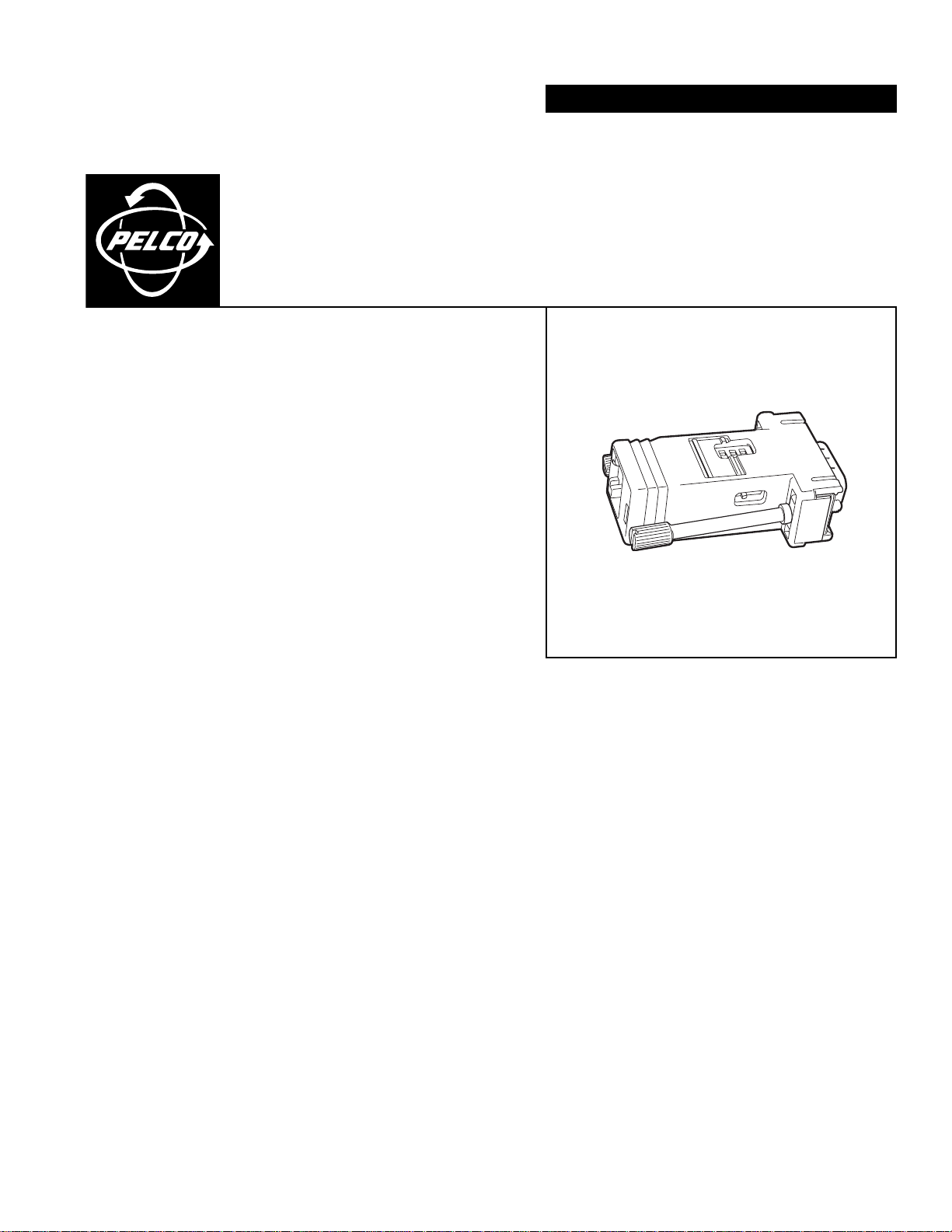
DESCRIPTION
MODELS
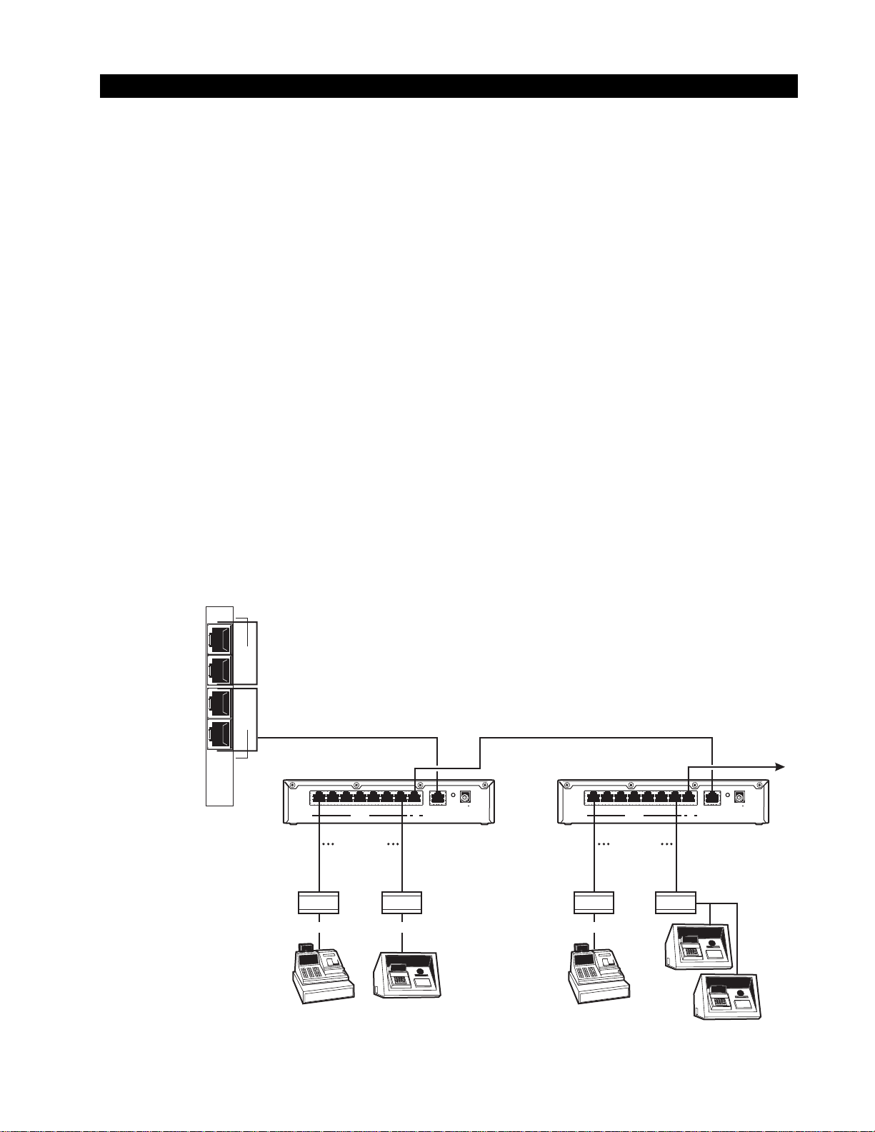
The DX2000 Data Adapters are used to connect any serial device, such as a cash register, retail point-of-sale (POS) terminal, or
bank automated teller machine (ATM), to the DX2000 Digital Video Recorder (DVR) or DX2000 Data Hub.
Each DX2000 DVR can directly control one device per data port (the DX2000 DVR has four ports). In order to control multiple
devices through a single data port, you must use a data hub. Up to seven devices can be connected to each data hub and each
device requires an adapter. Up to four DX2000 Data Hubs can be daisy-chained together. Refer to Figure 1.
The data adapters convert serial RS-232 data to optical code for use by the DVR or data hub. They also provide electrical
isolation for the POS/ATM devices. The data adapters’ output is an RJ-45 connector that lets you connect RJ-45 or RJ-11
modular cable to the DVR or data hub.
Typically, the DX2000DA9 Data Adapter is used when the serial device has a serial port dedicated to output to the DVR. If all of
the serial device’s ports are being used by other devices, you can use the DX2000DA9T or DX2000DA25T to tap into a port and
allow data to flow to the existing device in addition to the DVR.
DX2000DA9 DB9 adapter connects directly to POS/ATM device’s output data port; includes 25-foot (7.6 m) modular RJ-45
cable and DB9 gender changer
DX2000DA9T DB9 adapter connects to POS/ATM device’s output data cable; includes 25-foot (7.6 m) modular RJ-45 cable
and a “Y” cable
DX2000DA25T DB25 “T” adapter connects directly to POS/ATM device’s output data port or cable; can also connect to an
ATM’s network router output port; includes 25-foot (7.6 m) modular RJ-45 cable
OPTIONAL COMPATIBLE PRODUCTS
DX2000DH Data Hub. The DX2000DH Data Hub provides local connection for up to seven additional ATM or cash register/
POS devices. The hub allows transaction data to be delivered to the DX2000 over a single cable. The devices
can be up to 4,000 feet (1,219 m) from the DVR, and up to four data hubs can be daisy-chained together.
1
D
A
T
2
A
P
O
3
R
T
S
4
RS-422
PELCO DVR
DATA HUB
(DX2000DH)
123 4567IN
DATA PORT
7 DEVICES
PELCO
DATA ADAPTER
(DX2000DA)
RS-232 RS-232 RS-232
HUB DVR/HUB
RS-422
PELCO DVR
DATA HUB
(DX2000DH)
RESET
9-12V~
AC/DC
OUT
50/60hz
Use Only UL Listed
Class 2 Power Supply
1234 567IN
DATA PORT
TO ADDITIONAL
DVR DATA HUBS
RESET
OUT
HUB DVR/HUB
9-12V~
AC/DC
50/60hz
Use Only UL Listed
Class 2 Power Supply
7 DEVICES
PELCO
DATA ADAPTER
(DX2000DA)
ATM NETWORK
OR
POS TERMINAL
C697M-A (7/02) 3
Figure 1. DX2000DVR, DX2000DH, DX2000DA Data Connections
ATM
POS TERMINAL
ATM
ATM
20167
Page 4

D
C
E
R
X
T
X
R
C
K
T
C
K
POS CONFIGURATIONS
DX2000DA9 POS CONFIGURATION
Use the DX2000DA9 Data Adapter to connect a POS device’s DB9 serial output port to the DVR or data hub. You can use RJ-45
or RJ-11 cable.
DX2000DA9T POS CONFIGURATION
RJ-45 OR RJ-11 CABLE
Figure 2. DX2000DA9 POS Configuration
Figure 3. DX2000DA9T POS Configuration
TO DX2000 DVR OR
DX2000 DATA HUB
RJ-45 OR
RJ-11CABLE
EXISTING DATA
CABLE
20158
TO DX2000 DVR
OR DX2000
DATA HUB
Use the DX2000DA9T Data Adapter and “Y” cable to connect a POS device’s DB9 serial output port to an existing output data
cable (pole display). Use RJ-45 or RJ-11 cable from the data adapter to the DVR or data hub.
DX2000DA25T POS CONFIGURATION
Figure 4. DX2000DA25T POS Configuration
The DX2000DA25T can be used to connect the DVR or data hub to a POS device’s DB25 serial port and to an existing output
data cable (pole display). Use RJ-45 or RJ-11 cable from the data adapter to the DVR or data hub.
RJ-45 OR RJ-11 CABLE
TO DVR OR DATA HUB
E
C
D
K
R
C
X
R
C
K
T
X
T
EXISTING DATA
CABLE
20166
4 C697M-A (7/02)
Page 5

D
C
E
R
X
T
X
R
C
K
T
C
K
D
C
E
R
X
T
X
R
C
K
T
C
K
ATM CONFIGURATIONS
DX2000DA9 ATM CONFIGURATION
Figure 5. DX2000DA9 ATM Configuration
Use the DX2000DA9 Data Adapter to connect an ATM’s DB-9 serial output port to the DVR or data hub. You can use an RJ-45
or RJ-11 cable.
DX2000DA25T ATM CONFIGURATION
SNA NETWORK CABLE
Figure 6. DX2000DA25T ATM Configuration
Use the DX2000DA25T Data Adapter to connect the existing DB25 SNA (Systems Network Architecture) network cable to the
ATM. Use RJ-45 or RJ-11 cable from the data adapter to the DVR or data hub.
RJ-45 OR RJ-11 CABLE
RJ-45 OR RJ-11 CABLE
TO DVR OR DATA HUB
TO DX2000 DVR OR
DX2000 DATA HUB
20161
E
C
D
K
C
R
X
R
K
C
T
X
T
20162
DX2000DA25T ATM ROUTER OR MODEM CONFIGURATION
RJ-45 OR RJ-11 CABLE
BANK ROUTER OR MODEM
Figure 7. DX2000DA25T Router or Modem Configuration
Use the DX2000DA25T Data Adapter to connect the SNA network router (or modem) to the SNA network cable. Use RJ-45 or
RJ-11 cable from the data adapter to the DVR or data hub.
TO DVR OR DATA HUB
D
E
C
K
R
C
R
X
K
C
T
X
T
SNA NETWORK
CABLE (TO ATMs)
20163
C697M-A (7/02) 5
Page 6

D
C
E
D
C
E
RXR
X
TXT
X
R
C
K
R
C
K
T
C
K
T
C
K
20165
R
X
T
X
SWITCH SETTINGS
DX2000DA9/DX2000DA9T ADAPTER SWITCH SETTINGS
SW2
SW1
X
X
T
R
20164
Figure 8. DX2000DA9 Adapter Switch Settings
Switch SW1 lets you choose between data transmission (TX) or reception (RX) for the POS/ATM device’s output. Set the switch
to the TX position (factory default) when connecting directly to the device’s DB9 output port. If connecting to the device’s
existing output data cable, you may have to change the switch to the RX position if you are not using a straight data cable.
The three SW2 handshake switches let you enable RS-232 hardware handshaking for the device’s data port. Set all three to ON
(up) to enable and all three down to disable.
DX2000DA25T ADAPTER SWITCH SETTINGS
Figure 9. DX2000DA25T Adapter Switch Settings
The data select switch (left switch) lets you choose between data transmission (TX) or reception (RX) for the POS/ATM device’s
output. Set the switch to the TX position (factory default) when connecting directly to the device’s DB25 output port. If
connecting to the device’s existing output data cable, you may have to change the switch to the RX position if you are not using
a straight data cable.
For an ATM network connection, the data clock select switch (right switch) lets you choose between the ATM network’s
transmit (TCK) and receive (RCK) clock. You may have to change the switch position depending on the type of network
connection being used.
The data select and data clock select switches typically should be set to the same position (both transmit or receive).
6 C697M-A (7/02)
Page 7

WARRANTY AND RETURN INFORMATION
WARRANTY
Pelco will repair or replace, without charge, any merchandise proved defective in material or
workmanship for a period of one year after the date of shipment. Exceptions to this warranty are
as noted below:
• Five years on Pelco manufactured cameras (CC3500/CC3600/CC3700 and MC3500/MC3600
Series); two years on all other cameras.
• Three years on Genex® Series (multiplexers, server, and keyboard).
•Two years on all standard motorized or fixed focal length lenses.
•Two years on Legacy®, Camclosure™ Camera Systems, CM6700/CM6800/CM8500/CM9500/
CM9740/CM9760 Matrix, DF5 and DF8 Series Fixed Dome products.
•Two years on Spectra®, Esprit™, and PS20 Scanners, including when used in continuous
motion applications.
•Two years on Esprit™ and WW5700 series window wiper (excluding wiper blades).
• Eighteen months on DX Series digital video recorders.
• One year (except video heads) on video cassette recorders (VCRs). Video heads will be
covered for a period of six months.
• Six months on all pan and tilts, scanners or preset lenses used in continuous motion applications (that is, preset scan, tour and auto scan modes).
Pelco will warrant all replacement parts and repairs for 90 days from the date of Pelco
shipment. All goods requiring warranty repair shall be sent freight prepaid to Pelco, Clovis,
California. Repairs made necessary by reason of misuse, alteration, normal wear, or accident
are not covered under this warranty.
Pelco assumes no risk and shall be subject to no liability for damages or loss resulting from the
specific use or application made of the Products. Pelco’s liability for any claim, whether based on
breach of contract, negligence, infringement of any rights of any party or product liability, relating
to the Products shall not exceed the price paid by the Dealer to Pelco for such Products. In no
event will Pelco be liable for any special, incidental or consequential damages (including loss of
use, loss of profit and claims of third parties) however caused, whether by the negligence of
Pelco or otherwise.
The above warranty provides the Dealer with specific legal rights. The Dealer may also have
additional rights, which are subject to variation from state to state.
If a warranty repair is required, the Dealer must contact Pelco at (800) 289-9100 or (559) 292-1981 to
obtain a Repair Authorization number (RA), and provide the following information:
1. Model and serial number
2. Date of shipment, P.O. number, Sales Order number, or Pelco invoice number
3. Details of the defect or problem
If there is a dispute regarding the warranty of a product which does not fall under the warranty conditions
stated above, please include a written explanation with the product when returned.
Method of return shipment shall be the same or equal to the method by which the item was received by
Pelco.
RETURNS
In order to expedite parts returned to the factory for repair or credit, please call the factory at (800) 2899100 or (559) 292-1981 to obtain an authorization number (CA number if returned for credit, and RA
number if returned for repair).
All merchandise returned for credit may be subject to a 20% restocking and refurbishing charge.
Goods returned for repair or credit should be clearly identified with the assigned CA or RA number and
freight should be prepaid. Ship to the appropriate address below.
If you are located within the continental U.S., Alaska, Hawaii or Puerto Rico:
Service Department
Pelco
3500 Pelco Way
Clovis, CA 93612-5699
If you are located outside the continental U.S., Alaska, Hawaii or Puerto Rico:
Intermediate Consignee Ultimate Consignee
American Overseas Air Freight Pelco
320 Beach Road 3500 Pelco Way
Burlingame, CA 94010 Clovis, CA 93612-5699
USA USA
REVISION HISTORY
Manual # Date Comments
C697M 4/02 Original version.
C697M-A 7/02 Manual revised because of a change to the DX2000DA9T adapter and inclusion of a “Y” cable.
® Pelco, the Pelco logo, Spectra, Genex, Legacy, and Coaxitron are registered trademarks of Pelco. © Copyright 2002, Pelco.
™ Esprit and Camclosure are trademarks of Pelco. All rights reserved.
C697M-A (7/02) 7
Page 8

®
World Headquarters
3500 Pelco Way
Clovis, California 93612 USA
USA & Canada
Tel: 800/289-9100
Fax: 800/289-9150
International
Tel: 1-559/292-1981
Fax: 1-559/348-1120
www.pelco.com
ISO9001
Orangeburg, New York Las Vegas, Nevada Eindhoven, The Netherlands Wokingham, United Kingdom Montreal, Canada
 Loading...