

Page 1
®
DX1000 Series
Digital Video Recorder
Installation/
Operation Manual
C680M-G (7/01)
Pelco • 3500 Pelco Way • Clovis, CA 93612-5699 USA • www.pelco.com
In North America and Canada: Tel (800) 289-9100 • FAX (800) 289-9150
International Customers: Tel +1(559) 292-1981 • FAX +1(559) 348-1120
Page 2

CONTENTS
Section Page
IMPORTANT SAFEGUARDS AND WARNINGS................................................................3
DESCRIPTION...................................................................................................................3
MODELS ....................................................................................................................3
FRONT PANEL CONTROLS..............................................................................................4
INSTALLATION ..................................................................................................................4
PROGRAMMING ...............................................................................................................6
CAMERA MENU ........................................................................................................7
ALL RESOLUTION MENU ........................................................................................10
ALARM OUTPUT MENU ..........................................................................................11
TIME MENU ..............................................................................................................13
PASSWORD MENU..................................................................................................14
HELP.........................................................................................................................15
OPERATION .....................................................................................................................16
VIEWING CAMERAS................................................................................................16
RECORDING ............................................................................................................16
MANUAL RECORDING ....................................................................................16
AUTOMATIC SCHEDULED RECORDING .......................................................16
AUTOMATIC EVENT RECORDING ................................................................. 16
RECORDING EXAMPLE ..................................................................................17
SAVING VIDEO.........................................................................................................17
PLAYBACK ...............................................................................................................18
START PLAYBACK...........................................................................................18
SEARCH ...........................................................................................................18
FAST PLAYBACK .............................................................................................18
PAUSE PLAYBACK ..........................................................................................18
FRAME-BY-FRAME PLAYBACK ......................................................................18
CHANGE CAMERA BEING PLAYED BACK.....................................................18
STOP PLAYBACK.............................................................................................19
PLAYBACK FOLLOWING TIME CHANGES ....................................................19
POWER FAILURE.....................................................................................................19
ALARM OPERATI0N................................................................................................. 20
ALARM RELAY OUTPUT OPERATION............................................................20
TROUBLESHOOTING ......................................................................................................22
SPECIFICATIONS.............................................................................................................22
REGULATORY NOTICES .................................................................................................23
WARRANTY AND RETURN INFORMATION....................................................................24
LIST OF ILLUSTRATIONS
Figure Page
1 DX1000 Series DVR Front Panel.......................................................................4
2 DX1000 Series DVR Installation ........................................................................4
3 Menu Tree..........................................................................................................6
4 Recording and Playback When Hour Is Set Back.............................................19
LIST OF TABLES
Table Page
AVideo Coaxial Cable Requirements ...................................................................5
B Maximum Frames per Second...........................................................................8
CAverage Recording Times.................................................................................17
2 Pelco Manual C680M-G (7/01)
Page 3
IMPORTANT SAFEGUARDS AND WARNINGS
Prior to installation and use of this product, the following WARNINGS should be observed.
1. Installation and servicing should only be done by qualified service personnel and conform to all local codes.
2. Unless the unit is specifically marked as a NEMA Type 3, 3R, 3S, 4, 4X ,6 or 6P enclosure, it is designed for indoor use only and it must not be installed where exposed to
rain and moisture.
3. The installation method and materials should be capable of supporting four times the
weight of the unit.
4. To reduce fire or shock hazard, do not expose the unit to rain or moisture.
The product and/or manual may bear the following marks:
Please thoroughly familiarize yourself with the information in this manual prior to installation
and operation.
DESCRIPTION
The DX1000 Series Digital Video Recorder (DVR) is a compact recorder that can store and
play back images from four cameras. The DVR can be placed on a shelf or desktop for easy
access to the front panel controls for operation and programming.
Live video from all four cameras can be viewed while recording. Recording can be done
continuously or for a scheduled time in a 24-hour period. Each camera has its own alarm input for alarm recording.
Two models, one with a 30 GB hard drive and the second with a 60 GB hard drive, generally allow continuous recording up to two or four weeks respectively under the most common recording conditions. Recording time will vary depending on image size, number of
cameras recorded, resolution selection, and record rate.
This symbol indicates that dangerous
voltage constituting a risk of electric
shock is present within this unit.
This symbol indicates that there are
important operating and maintenance
instructions in the literature accompanying this unit.
CAUTION:
TO REDUCE THE RISK OF ELECTRIC SHOCK
DO NOT REMOVE COVER (OR BACK).
NO USER-SERVICEABLE PARTS INSIDE.
REFER SERVICING TO QUALIFIED
SERVICE PERSONNEL.
AVIS:
RISQUE DE CHOC ELECTRIQUE.
NE PAS OUVRIR.
Recording can be stopped at any time to play back video. Search functions during playback
allow frame-by-frame viewing, fast playback, and playback of alarm events.
The DVR uses proprietary compression algorithms to prevent alteration of the video image,
as well as password protection to guard against unauthorized or unintentional recording or
playback.
MODELS
DX1004-030 Four-channel digital video recorder, 30 GB hard drive, simplex operation
DX1004-060 Same as the DX1004-030, except has 60 GB hard drive
Pelco Manual C680M-G (7/01) 3
(cannot record and play back video at the same time), 80-240 VAC,
NTSC/PAL
Page 4
FRONT PANEL CONTROLS
Power
1234
5678
90
Stop Function
INSTALLATION
The following parts are supplied:
1 DX1000 Series DVR (refer to Figure 1)
1 Induced Voltage Protector (refer to item 4c in Figure 2)
1 230 VAC power cord adapter
Record
Figure 1. DX1000 Series DVR Front Panel
Search Play/Pause Search
Figure 2. DX1000 Series DVR Installation
4 Pelco Manual C680M-G (7/01)
Page 5

WARNING:
Adequate
ventilation is required for
proper operation of the
DVR. Allow two inches of
space above the unit and on
each side for air circulation.
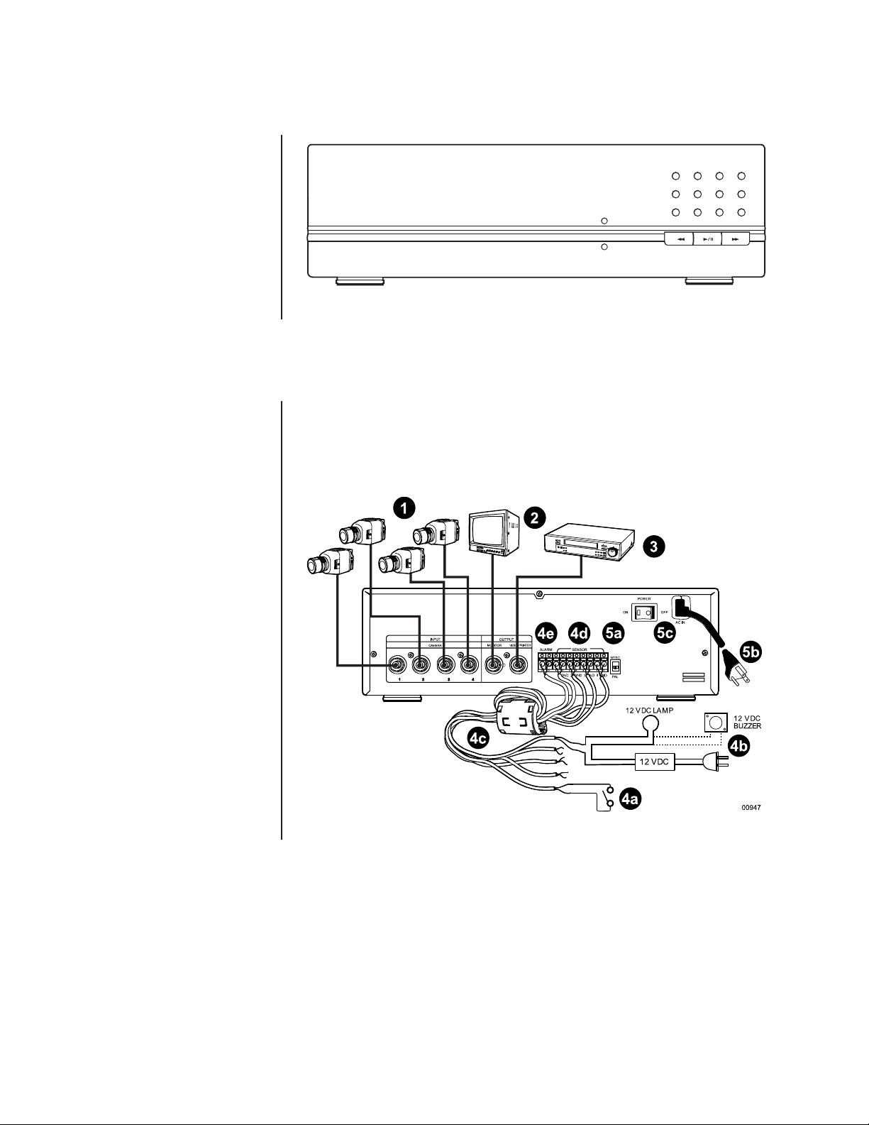
1 Connect cameras to the CAMERA INPUT connectors (BNC) on the rear of the DVR.
Refer to Table A for video coaxial cable distances.
2 Connect a monitor to the MONITOR OUTPUT connector (BNC) on the rear of the DVR.
Refer to Table A for video coaxial cable distances.
3 To save data from the DVR, connect a peripheral recording device to the VIDEO
PRINTER OUTPUT connector (BNC) on the rear of the DVR. Refer to Table A for
video coaxial cable distances.
Table A. Video Coaxial Cable Requirements
Cable Type* Maximum Distance
RG59/U 750 ft (229 m)
RG6/U 1,000 ft (305 m)
RG11/U 1,500 ft (457 m)
*Minimum cable requirements:
75 ohms impedance
All-copper center conductor
All-copper braided shield with 95% braid coverage
4 Connect alarm inputs and alarm relay output as follows:
a. Inputs – Connect wiring (not supplied) to your alarms (not supplied). Two wires
are required for each alarm. You can have one alarm for each camera.
b. Output – Connect wiring (not supplied) to a 12 VDC light or buzzer (not supplied).
Two wires are required.
c. Bring the alarm input and output wiring to the back of the DVR and thread the
wiring through the Induced Voltage Protector (supplied). Loop the wiring over the
voltage protector and thread it through the voltage protector a second time.
d. Connect the alarm input wires to the SENSOR connectors.
e. Connect the light or buzzer to the ALARM output connectors.
5 Connect the recorder to power.
a. Place the NTSC/PAL switch in the proper mode.
b. If applicable, connect the 230 VAC adapter to the end of the power cord. Plug in
the power cord.
c. Turn on the DVR. When the recorder is turned on for the first time, the Help
screens will appear on the monitor. To bypass the Help screens, press the Play/
Pause button.
6 Turn on the cameras and monitor. The DVR begins recording the cameras.
IMPORTANT– If you have any unused camera inputs, the video appears washed out.
The degree of washout depends on how many inputs have no cameras connected to
them. If only one camera is connected, the video is completely washed out. When you
program the DVR (step 9), you must turn off any unused camera inputs. Video
will then appear normal.
7 Go to
8 Initialize the DVR. Refer to the instructions on a separate sheet.
Time Menu
in the
Programming
section and set the time and date.
This is a necessary step as the DVR may not operate properly during playback and
search operation if there are conflicts in the date and time. Initializing the DVR erases
all data on the hard disk drive so that you start with a clean file management system
for your recordings.
9 Proceed to the
password (optional).
Programming
section to set up the recording parameters and enter a
Pelco Manual C680M-G (7/01) 5
Page 6
PROGRAMMING
Programming allows you to configure camera and alarm operation, set the system date and
time, and define a password.
Camera
All Resolution
Alarm Output
Tim e
Password
Exit
Help: ON
SETUP MENU
CAMERA
Camera 1: On
Camera 2: On
Camera 3: On
Camera 4: On
Preview: On
fps (Fr ame Per Second): 01
Quit
RESOLUTION
Lowest resolution: Off
Low resolution: Off
St andard resolution: On
High resol ution: Off
Highest resolution: Off
Quit
ALARM OUTPUT
Enable Alarm Output: 00
Disable Alarm Output: 24
Automatically Enable
Alarm Outpu t: On
Quit
TIME
Yea r
/
Month/Date/Hour/Minute
Daylight Saving Time: On
Quit
s
CAMERA 1*
Camera operation: On
Automatic Recording: On
Automatic recording time change
Resolution
Quit
* Same menu for cameras 2-4.
/
Month/Date/Hour/Minute
Yea r
Daylight Saving Time: On
OR
-Starting Time: /Date/Hour
-Ending Time: Month/Date/Hour
Quit
RESOLUTION
Lowest resolution: Off
Low resolution: Off
St an dard resolution: On
High resolution: Off
Highest resolution: Off
Quit
TIME
s
Month
PASSWORD
User level passwor d protection: Off
Password chan ge
Quit
00946
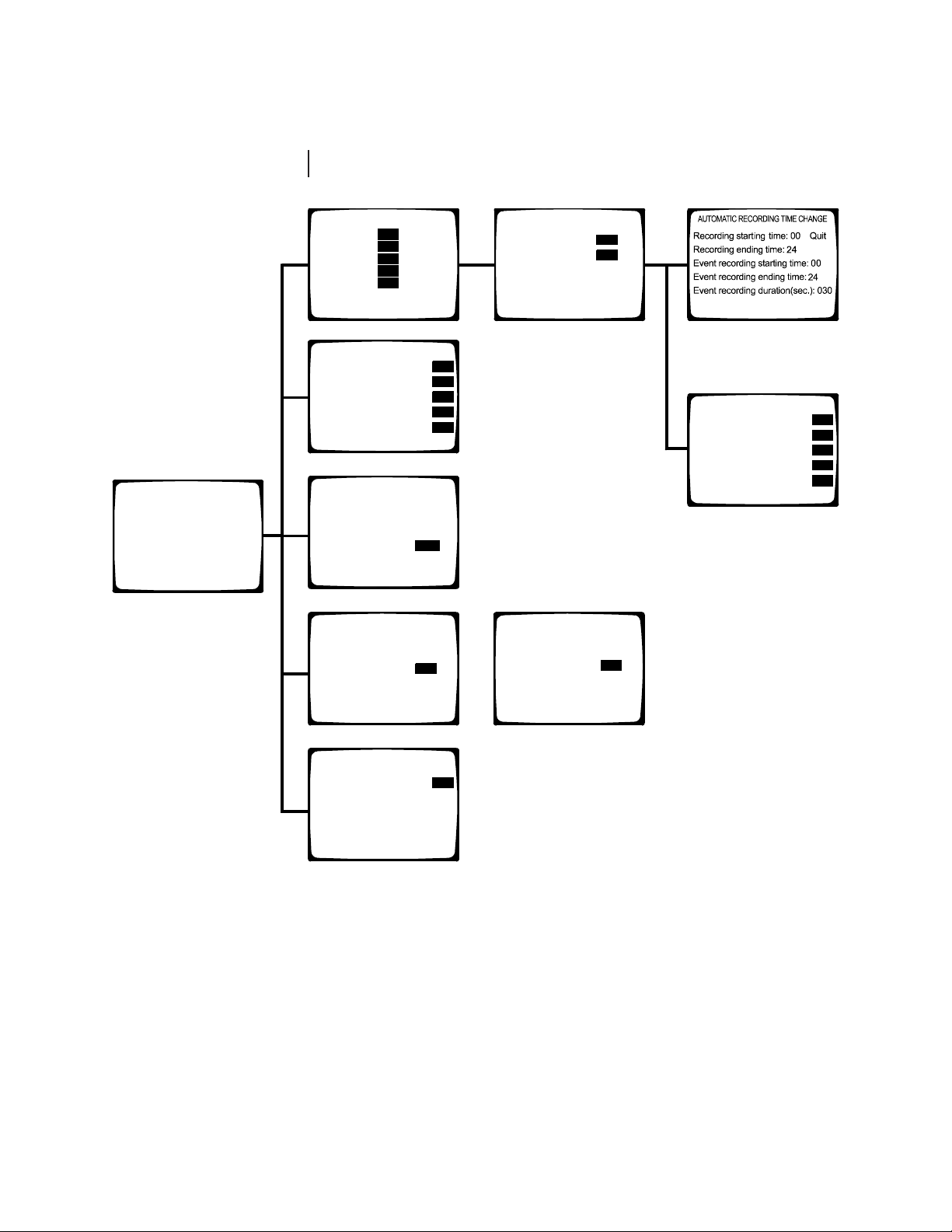
Figure 3. Menu Tree
6 Pelco Manual C680M-G (7/01)
Page 7
CAMERA MENU
Use this menu to define the following:
• Which cameras the DVR will record
• Whether starting and stopping of recording will be done manually or automatically
• What the record rate (frames per second) will be
• What the recording resolution (low to high) will be
• Whether live video can be viewed in record mode
• Starting and stopping times for scheduled recording
Skip steps 1 and 2 if you are already in the Setup Menu.
1. Press and hold the Function button. The Function Key List appears. Keep holding the
Function button.
2. Press and release the 0 button, and then release the Function button. Enter the password if requested. The Setup Menu appears.
FUNCTION KEY LIST
0 : Setup
1 : Camera 1 recording/stop
2 : Camera 2 recording/stop
3 : Camera 3 recording/stop
4 : Camera 4 recording/stop
5 : All the cameras recording
6 : All the cameras stop
: Alarm On
: Alarm Off
SETUP MENU
Camera
All Resolution
Alarm Output
Tim e
Password
Exit
Help: ON
TIP:
You can return to the
previous menu at any time
by pressing the Stop button.
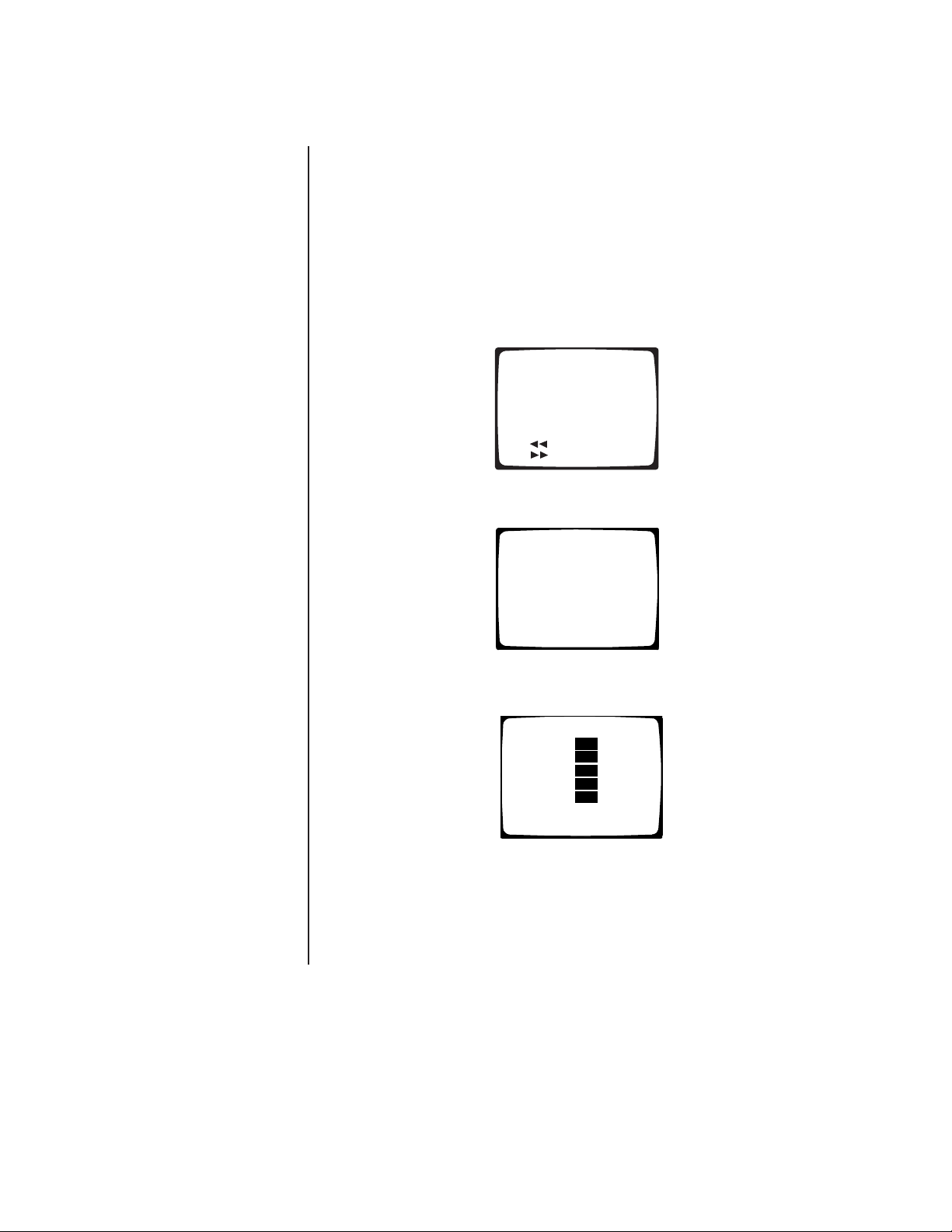
3. Use the Search (<</>>) buttons to move around within the menu. Highlight Camera
and then press the Play/Pause button to select. The Camera menu appears.
CAMERA
Camera 1: On
Camera 2: On
Camera 3: On
Camera 4: On
Preview: On
fps (Fr ame Per Second): 01
Quit
4. If the Preview field shows On, live video from the cameras will appear on the monitor
while the DVR is recording or is in recording standby mode (not recording).
If the Preview field shows Off, live video will not be shown.
To change the Preview status, use the Search (<</>>) buttons to highlight Preview,
and then press the Play/Pause button to toggle between On and Off.
Pelco Manual C680M-G (7/01) 7
Page 8
5. The fps (Frame Per Second) field shows the recording rate for all cameras.
To change the fps, use the Search (<</>>) buttons to highlight fps, and then use the
number keypad to enter the frames per second. The maximum frames per second is
determined by the number of cameras being recorded and whether the Preview feature
is on or off. Refer to Table B for the maximum frames per second. Refer to Table C in
the
Operation
section for recording times.
Table B. Maximum Frames per Second
Cameras Preview On Preview Off
115 30
2 5 7
3 3 5
4 2 3
6. To configure any of the four cameras, use the Search (<</>>) buttons to highlight the
camera number, and then press the Play/Pause button. The menu for that camera
appears.
CAMERA 1*
Camera operation: On
Automatic Recording: On
Automatic recording time change
Resolution
Quit
* Same menu for cameras 2-4.
00424
IMPORTANT NOTE:
If
camera inputs are not used,
make sure Camera
Operation is OFF. Video
washout occurs if unused
inputs are left on. The
degree of washout depends
on how many inputs have
no cameras connected to
them. The most severe case
is when all inputs are turned
on but only one camera is
connected; in this case the
video is completely washed
out.
CAMERA OPERATION
7. Use the Search (<</>>) buttons to highlight Camera Operation, and then press the
Play/Pause button to toggle between On or Off. On means the DVR will record video
for that channel, and Off means it will not record video, even if a camera is connected.
AUTOMATIC RECORDING
8. Use the Search (<</>>) buttons to highlight Automatic Recording, and then press the
Play/Pause button to toggle between On or Off. On means the DVR will record automatically during the times you will select in the following steps. Off means you will
manually turn the recorder on and off.
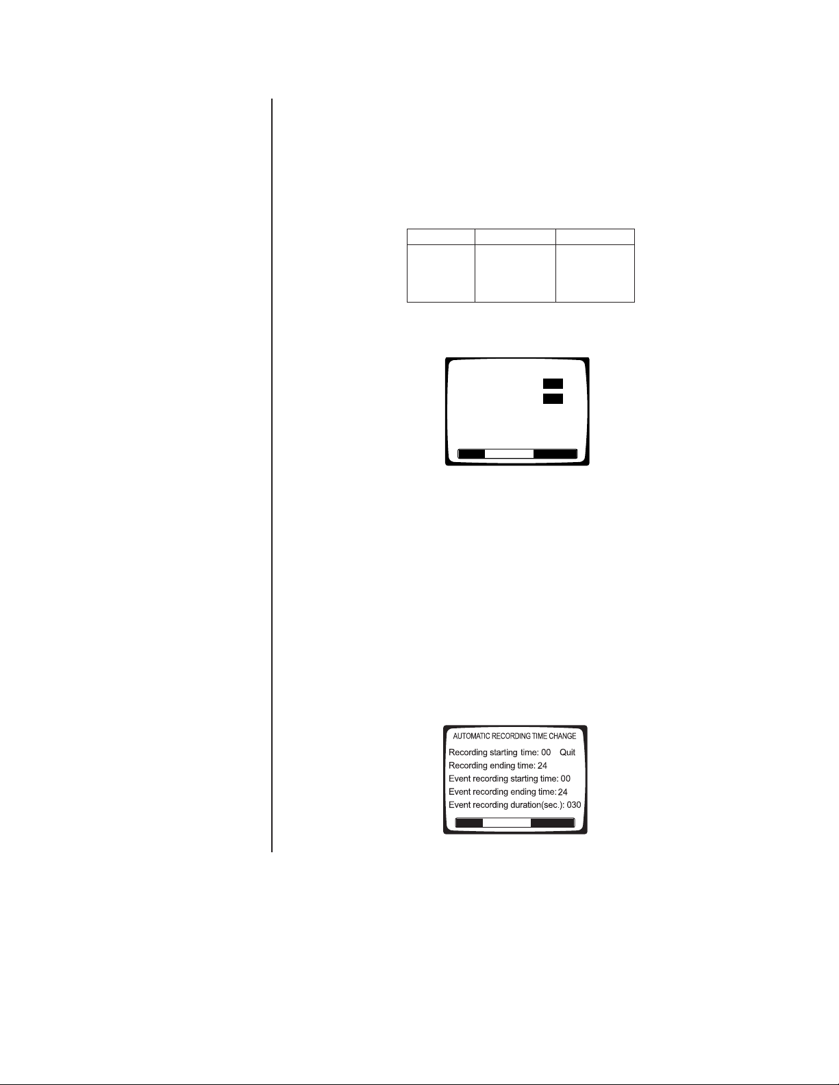
AUTOMATIC RECORDING TIME CHANGE
9. Use the Search (<</>>) buttons to highlight Automatic Recording Time Change, and
then press the Play/Pause button to select. The Automatic Recording Time Change
menu appears.
00426
8 Pelco Manual C680M-G (7/01)
Page 9

10. Use the Search (<</>>) buttons to highlight each field in the menu.
Recording Times
The recorder will record continuously between the specified times. Use the number
buttons to enter the hour of the starting time and ending time. Enter two digits. Enter
the hours in 24-hour format. For example, enter 08 for 8 a.m. and 15 for 3 p.m. For 24hour recording, enter a start time of 00 and an ending time of 24. For no recording, enter a start time of 24 and an end time of 00.
NOTE:
Recording and
event recording times
should be set for different
time periods. For example,
you may want to record
continuously in the daytime
when there is a lot of
activity, but record only
alarms at night.
Event Recording Times
Event recording means the recorder will only record if there are alarms during the
specified time period. Use the number buttons to enter the hour of the starting time
and ending time. Enter two digits. Enter the hours in 24-hour format. For example, enter 08 for 8 a.m. and 15 for 3 p.m. For 24-hour recording, enter a start time of 00 and
an ending time of 24. For no recording, enter a start time of 24 and an end time of 00.
Event Recording Duration
This is the time the recorder will continue recording after the alarm goes away. The
time can be set from 0 to 200 seconds.
Recording Bar
At the bottom of the screen is a bar that shows when recording will occur. Red is for
continuous recording, blue is for event recording, and white is for no recording. If you
overlap the continuous and event recording times, the bar will be red.
Quit
When you finish entering the times, use the Search (<</>>) buttons to highlight Quit,
and then press the Play/Pause button to select. The Camera Number menu appears.
RESOLUTION
11. In this step the camera’s resolution is set. You can set each camera’s resolution individually, allowing you to use different resolutions for the different cameras. Or you can
set the resolution for all cameras at one time; in this case, the resolution will be the
same for all cameras.
To set each camera’s resolution individually, follow the steps below.
If you want to use the same resolution for all cameras, skip this step and proceed to step 12 to finish the individual setup of cameras. Then set the resolution
for all cameras in the All Resolution menu (next section).
a. Use the Search (<</>>) buttons to highlight Resolution, and then press the Play/
Pause button to select. The Resolution menu appears.
RESOLUTION
Lowest resolution: Off
Low resolution: Off
St andard resolution: On
High resol ution: Off
Highest resolution: Off
Quit
b. Use the Search (<</>>) buttons to highlight a resolution, and then press the Play/
Pause button. When one resolution is turned On, all others are set to Off.
c. Use the Search (<</>>) buttons to highlight Quit, and then press the Play/Pause
button to select. The Camera Number menu appears.
d. Use the Search (<</>>) buttons to highlight Quit, and then press the Play/Pause
button to select. The Camera menu appears.
12. Repeat steps 6-11 to configure other cameras. When you finish configuring all cameras,
press the Stop button as many times as necessry to return to the Setup Menu. Highlight
another menu item in the Setup Menu and then press the Play/Pause button to select it,
or highlight Exit and then press the Play/Pause button to end the programming session.
Pelco Manual C680M-G (7/01) 9
Page 10

ALL RESOLUTION MENU
NOTE:
Setting the
resolution in this menu will
overwrite all camera
resolution settings made in
the individual camera
settings (step 11 of previous
section).
NOTE:
Higher resolutions
require more disk storage
space, reducing the
recording time; lower
resolutions need less disk
space, increasing the
recording time.
Use this menu to set the resolution for all cameras. If you want to use different resolutions
for the cameras, set the resolutions in the Camera menu (previous section).
Skip steps 1 and 2 if you are already in the Setup Menu.
1. Press and hold the Function button. The Function Key List appears. Keep holding the
Function button.
FUNCTION KEY LIST
0 : Setup
1 : Camera 1 recording/stop
2 : Camera 2 recording/stop
3 : Camera 3 recording/stop
4 : Camera 4 recording/stop
5 : All the cameras recording
6 : All the cameras stop
: Alarm On
: Alarm Off
2. Press and release the 0 button, and then release the Function button. Enter the password if requested. The Setup Menu appears.
SETUP MENU
Camera
All Resolution
Alarm Output
Tim e
Password
Exit
Help: ON
TIP:
Pressing the Stop
button also returns you to
the Setup Menu.
3. Use the Search (<</>>) buttons to highlight All Resolution, and then press the
Play/Pause button to select. The All Resolution menu appears.
RESOLUTION
Lowest resolution: Off
Low resolution: Off
St an dard resolution: On
High resolution: Off
Highest resolution: Off
Quit
4. Use the Search (<</>>) buttons to highlight a resolution, and then press the
Play/Pause button. When one resolution is turned On, all others are set Off.
5. Use the Search (<</>>) buttons to highlight Quit, and then press the Play/Pause button to select. The Setup Menu appears.
6. Use the Search (<</>>) buttons to highlight another menu item in the Setup Menu
and then press the Play/Pause button to select it, or highlight Exit and then press
the Play/Pause button to end the programming session.
10 Pelco Manual C680M-G (7/01)
Page 11

NOTE:
SETUP MENU
Camera
All Resolution
Alarm Output
Tim e
Password
Exit
Help: ON
The alarm output
programming does not
affect recording. It only
affects the operation of the
alarm output relay. For
event (alarm) recording,
Recording
refer to
Operation
section.
in the
ALARM OUTPUT MENU
The ALARM output on the rear panel is a single-pole, normally open, latching, dry contact.
This output can be used to notify you if there has been an alarm event that might require
review. The alarm output can be enabled or disabled (armed/disarmed) manually, or it can
be programmed to enable (arm) or disable (disarm) at the same time automatically every
day.
If the output is enabled and an alarm input is activated, the output relay will latch closed after a 20-second delay and will remain closed until it is manually disabled. The 20-second
delay allows you to enter your premises and disable the alarm output before it is activated.
The alarm output menu is used to set up automatic arming and disarming of the relay at
specified times each day. (For manual operation, refer to
the
Operation
capabilities of the DX1000 to notify you that an alarm event was recorded.
Application example:
A company has a rear door that is not to be opened for any reason between 5 p.m. and 7
a.m. During the day, the area around this door is recorded continuously, but to conserve
disk space, the area is only recorded at night if the door is opened. The owner does not
want to review the video unless the door was opened after hours.
In this case, the alarm output would be programmed to enable at 5 p.m. and disable at 7 a.m.
The DX1000 would also be programmed for automatic (continuous) recording from 7 a.m. to
5 p.m. and event recording from 5 p.m. to 7 a.m. (refer to
section).
At 5 p.m. continuous recording would cease. If an alarm input is activated, the DVR would
immediately begin recording the associated camera. The relay would latch closed after the
20-second delay. When the owner returned in the morning, a light attached to the relay
output would be on, indicating that there was an alarm during the night. A search for recorded video starting at 5 p.m. would immediately take you to the first alarm event. All
other events could be reviewed in sequence.
section.) This feature may be used in conjunction with the event recording
Alarm Relay Output Operation
Camera Menu
in the
Programming
in
To program the relay for automatic arming/disarming:
Skip steps 1 and 2 if you are already in the Setup Menu.
1. Press and hold the Function button. The Function Key List appears. Keep holding the
Function button.
FUNCTION KEY LIST
0 : Setup
1 : Camera 1 recording/stop
2 : Camera 2 recording/stop
3 : Camera 3 recording/stop
4 : Camera 4 recording/stop
5 : All the cameras recording
6 : All the cameras stop
: Alarm On
: Alarm Off
2. Press and release the 0 button, and then release the Function button. Enter the password if requested. The Setup Menu appears.
Pelco Manual C680M-G (7/01) 11
Page 12

3. Use the Search (<</>>) buttons to move around within the menu. Highlight Alarm Output and press the Play/Pause button to select. The Alarm Output menu appears.
ALARM OUTPUT
Enable Alarm Output: 00
Disable Alarm Output: 24
Automatically Enable
Alarm Output: On
Quit
00425
4. Use the Search (<</>>) buttons to highlight the fields for starting and ending times.
When you highlight a field, use the number buttons to enter the time. The starting and
ending times refer to the hour. Enter two digits. Enter the hours in 24-hour format. For
example, enter 08 for 8 a.m. and 15 for 3 p.m.
At the bottom of the screen is a bar that shows the hours when the alarm output will
be enabled. Red means enabled and white means disabled.
5. Use the Search (<</>>) buttons to highlight Automatically Enable Alarm Output, and
then press the Play/Pause button to toggle between On or Off.
TIP:
Pressing the Stop
button also returns you to
the Setup Menu.
6. When you finish, use the Search (<</>>) buttons to highlight Quit, and then press the
Play/Pause button to select. The Setup Menu appears.
7. Use the Search (<</>>) buttons to highlight another menu item in the Setup Menu
and then press the Play/Pause button to select it, or highlight Exit and then press
the Play/Pause button to end the programming session.
12 Pelco Manual C680M-G (7/01)
Page 13

TIME MENU
The DVR uses the time and date to index video on the hard disk drive so you can find it
later. Changing the time can cause the DVR to work improperly when you try to play back
video. If you set the hour ahead, this is not a problem. But if you set the hour back, there
will be more than one recording at the same time. Therefore, you should refrain from making frequent changes as this will complicate searching by time and date. For more information, refer to
To set the system time and date:
Skip steps 1 and 2 if you are already in the Setup Menu.
1. Press and hold the Function button. The Function Key List appears. Keep holding the
Function button.
2. Press and release the 0 button, and then release the Function button. Enter the password if requested. The Setup Menu appears.
Playback Following Time Changes
FUNCTION KEY LIST
0 : Setup
1 : Camera 1 recording/stop
2 : Camera 2 recording/stop
3 : Camera 3 recording/stop
4 : Camera 4 recording/stop
5 : All the cameras recording
6 : All the cameras stop
SETUP MENU
Camera
All Resolution
Alarm Output
Tim e
Password
Exit
Help: ON
: Alarm On
: Alarm Off
in the
Operation
section.
TIP:
Pressing the Stop
button also returns you to
the Setup Menu.
3. Use the Search (<</>>) buttons to move around within the menu. Highlight Time and
press the Play/Pause button to select. The Time menu appears.
TIME
/
Month/Date/Hour/Minute
Yea r
Daylight Saving Time: On
Quit
s
Yea r
Daylight Saving Time: On
OR
-Starting Time: /Date/Hour
-Ending Time: Month/Date/Hour
Quit
TIME
/
Month/Date/Hour/Minute
s
Month
4. There are five fields for entering the date and time. The fields, from left to right, are for
the year, month, day, hour, and minute. Use the Search (<</>>) buttons to move between the fields. In each field enter two digits. For numbers below 10, enter a 0 as the
first digit. Enter the hour in 24-hour format; for example, 08 is 8 a.m. and 15 is 3 p.m.
5. Use the Search (<</>>) buttons to highlight Daylight Saving Time, and then press the
Play/Pause button to toggle between On or Off. If your unit is set for PAL operation,
also enter the starting and ending times.
6. Use the Search (<</>>) buttons to highlight Quit, and then press the Play/Pause but-
ton to select. The Setup Menu appears.
7. Use the Search (<</>>) buttons to highlight another menu item in the Setup Menu
and then press the Play/Pause button to select it, or highlight Exit and then press
the Play/Pause button to end the programming session.
Pelco Manual C680M-G (7/01) 13
Page 14

PASSWORD MENU
Use this menu to change the password (optional).
Skip steps 1 and 2 if you are already in the Setup Menu.
1. Press and hold the Function button. The Function Key List appears. Keep holding the
Function button.
2. Press and release the 0 button, and then release the Function button. Enter the password if requested. The Setup Menu appears.
3. Use the Search (<</>>) buttons to move around within the menu. Highlight Password
and press the Play/Pause button to select. The Password menu appears.
FUNCTION KEY LIST
0 : Setup
1 : Camera 1 recording/stop
2 : Camera 2 recording/stop
3 : Camera 3 recording/stop
4 : Camera 4 recording/stop
5 : All the cameras recording
6 : All the cameras stop
: Alarm On
: Alarm Off
SETUP MENU
Camera
All Resolution
Alarm Output
Tim e
Password
Exit
Help: ON
PASSWORD
User level password protection: Off
Password chan ge
Quit
4. Use the Search (<</>>) buttons to highlight User Level Password Protection, and then
press the Play/Pause button to toggle between On or Off.
ENTER PASSWORD
“Input your password.”
5. Use the Search (<</>>) buttons to highlight Password Change, and then press the
Play/Pause button to select. The Enter Password screen appears.
6. The DVR ships from the factory with a password of 0000. Enter four numbers for a
new password.
7. You will be prompted to verify your password by entering it a second time. If the two
passwords agree, “Registered” appears on the screen and then the Password menu
reappears. If the passwords do not agree, “Registration Cancelled” appears on the
screen and then the Password menu reappears.
TIP:
Pressing the Stop
button also returns you to
the Setup Menu.
8. Use the Search (<</>>) buttons to highlight Quit, and then press the Play/Pause button to select. The Setup Menu appears.
9. Use the Search (<</>>) buttons to highlight another menu item in the Setup Menu
and then press the Play/Pause button to select it, or highlight Exit and then press
the Play/Pause button to end the programming session.
14 Pelco Manual C680M-G (7/01)
Page 15

HELP
SETUP MENU
Camera
All Resolution
Alarm Output
Tim e
Password
Exit
Help: ON
If the Help function is enabled, the Help screens appear on the monitor whenever power is
turned on.
Skip steps 1 and 2 if you are already in the Setup Menu.
1. Press and hold the Function button. The Function Key List appears. Keep holding the
Function button.
FUNCTION KEY LIST
0 : Setup
1 : Camera 1 recording/stop
2 : Camera 2 recording/stop
3 : Camera 3 recording/stop
4 : Camera 4 recording/stop
5 : All the cameras recording
6 : All the cameras stop
: Alarm On
: Alarm Off
2. Press and release the 0 button, and then release the Function button. Enter the
passward if requested. The Setup Menu appears.
3. Use the Search (<</>>) buttons to highlight Help, and then press the Play/Pause button to select ON or OFF.
Pelco Manual C680M-G (7/01) 15
Page 16

OPERATION
NOTE:
Automatic Recording in the Camera menu
must be OFF.
The Record LED on the front panel indicates what the DVR is doing.
Recording: Red (blinking)
Playback: Green (steady)
Fast Playback: Green (blinking)
Alarm Event Recording Enabled: Yellow (steady)
Stop: Off
VIEWING CAMERAS
If the Preview feature in the Camera menu is On, you can view live video on the monitor.
Video is displayed full-screen only if one camera is turned on. If more than one camera is
turned on, video is shown in a quad view.
If the Preview feature in the Camera menu is Off, you cannot view live video on the monitor.
RECORDING
MANUAL RECORDING
1. Press and hold the Function button. The Function Key list appears. Keep holding the
Function button.
FUNCTION KEY LIST
0 : Setup
1 : Camera 1 recording/stop
2 : Camera 2 recording/stop
3 : Camera 3 recording/stop
4 : Camera 4 recording/stop
5 : All the cameras recording
6 : All the cameras stop
: Alarm On
: Alarm Off
NOTE:
Turning off
cameras does not save
video for those cameras. All
that does is provide more
disk space to record other
cameras. When the hard
disk drive is full, the DVR
will start overwriting the
oldest video recorded.
2. Press buttons 1-6 to start or stop recording. Buttons 1-4 are toggle switches: if a camera is recording, pressing a button will stop recording; if a camera is not recording;
pressing a button will start recording.
3. Release the Function button. Cameras set to record will record continuously until you
repeat steps 1 and 2 and stop recording.
AUTOMATIC SCHEDULED RECORDING
Scheduled recording allows you to program the DVR to turn on and off at specified times
each day. This way you record only when you need to and can conserve hard disk drive
space. When the hard disk drive is full, the DVR starts to overwrite the oldest data. Refer to
Table C to determine approximately how much data can be stored on the hard disk drive
and when you should back up your data.
Refer to
Camera Menu
If you need to stop recording a camera before the programmed end time, you must go back
into the programming menus and turn off the automatic recording for that camera.
in the
Programming
section to set the start and stop times for recording.
AUTOMATIC EVENT RECORDING
Event recording allows you to program the DVR to record only when an alarm input is activated. The DVR will record for as long as the alarm input is active. After the alarm goes
away, the DVR will continue to record for the programmed time. Event recording allows you
to conserve even more hard disk drive space than scheduled recording. When the hard
disk drive is full, the DVR starts to overwrite the oldest data. Refer to Table C to determine
approximately how much data can be stored on the hard disk drive and when you should
back up your data.
Refer to
Camera Menu
in the
Programming
section to set the start and stop times for recording.
If you need to stop recording a camera before the programmed end time, you must go back
into the programming menus and turn off the automatic recording for that camera.
16 Pelco Manual C680M-G (7/01)
Page 17

RECORDING EXAMPLE
A company has a rear door that is not to be opened for any reason between 5 p.m. and 7
a.m. During the day, the area around this door is recorded continuously (scheduled recording), but to conserve disk space, the area is only recorded at night if the door is opened
(event recording).
In this case, the recorder would be programmed for scheduled (continuous) recording from
7 a.m. to 5 p.m. and event recording from 5 p.m. to 7 a.m. (refer to
Programming
SAVING VIDEO
When the hard disk drive is full, the DVR starts to overwrite the oldest data. Refer to Table
C to determine approximately how much data can be stored on the hard disk drive and
when you should back up your data. Data should be backed up on a regular basis to ensure that important video is not lost.
section).
Camera Menu
in the
NOTE:
Turning off cameras does not save video for those cameras. All that does is
provide more disk space to record other cameras. When the hard disk drive is full, the
DVR will start overwriting the oldest video recorded.
To save video:
1. Connect a peripheral recording device, such as a VCR or video printer, to the PHOTO
PRINTER connector on the rear of the DVR.
2. Turn on the peripheral recording device. If the DVR is in the record mode, the video
also will be recorded on the peripheral device. If the DVR is in the playback mode, the
video will be recorded on the peripheral device.
Table C. Average Recording Times
DX1004-030
Resolution Cameras
Lowest 412221137
Low 41172936
Standard 41142735
High 41112534
Highest 4192433
DX1004-060
Resolution Cameras
Lowest 4143222314
Low 4135217312
Standard 4129214310
High 412221137
Highest 41172936
* Based on 24-hour recording
Frames/Sec.
Per Camera Per Camera Per Camera
Frames/Sec.
Per Camera Per Camera Per Camera
Days*
Days*
Frames/Sec.
Frames/Sec.
Days*
Days*
Frames/Sec.
Frames/Sec.
Days*
Days*
The recording times in Table C depend on the file size for each recorded picture. The file
size can vary with the scene, amount of motion, and other factors. The figures in Table C
represent the average recording times and do not guarantee recording times in a particular
application.
NOTE:
Values indicating video storage capacity are estimates only. These estimates
are to be used as guidelines in determining proper hard drive requirements. Many
user selectable factors such as image quality, recording rate, image content/motion,
and video noise will all affect the total amount of video that can be stored on a hard
drive. These video storage duration estimates will vary based on actual use. These
estimates are not an implied or expressed guarantee of actual performance.
Pelco Manual C680M-G (7/01) 17
Page 18

PLAYBACK
START PLAYBACK
To begin playback:
1. Press the Play/Pause button.
2. Enter the password if requested.
3. The Play window appears.
4. Press a number button (1-4) to select the camera to view. The camera channel ap-
5. Press the Search (>>) button to go to the time and date fields. Select the time and
PLAY
From 2000 / 01 / 01
to 2000 / 03 / 03
Data search is possible by Year/month/date.
Camera 3CH
Playing time
2000 / 02 / 05 / 09 / 00
*Input camera
channel number.
PLAY SCREEN
pears on the screen.
date you want to play back. At the top of the window, the “From” and “to” fields show
the time period that is recorded on the hard drive. You may choose the playback time
within this period.
At the bottom of the window are five fields for entering the playing time. The fields,
from left to right, are for the year, month, day, hour, and minute. Use the Search
(<</>>) buttons to move between the fields. In each field enter two digits. For numbers below 10, enter a 0 as the first digit. Enter the hour in 24-hour format; for example, 08 is 8 a.m. and 15 is 3 p.m.
6. Press the Play button. Playback begins. “PLAY” appears on the screen.
SEARCH
To search during playback, use the Search (<</>>) buttons. Press and hold the button for
the direction you want to search. As you hold the button, the search increases speed. Release the button when you find the video you want to view.
FAST PLAYBACK
To increase the playback speed, press the Search (>>) button once.
To resume playback at normal speed, press the Pause/Play button once.
PAUSE PLAYBACK
To pause playback:
1. Press the Play/Pause button to pause playback. “Pause” appears on the screen.
2. Press the Play/Pause button again to resume playback.
FRAME-BY-FRAME PLAYBACK
To play back one frame at a time:
1. Press the Play/Pause button to pause playback. “Pause” appears on the screen.
2. Use the Search (>>) buttons to move forward one frame at a time.
2. Press the Play/Pause button again to resume normal playback.
CHANGE CAMERA BEING PLAYED BACK
To view a different camera during playback, press the number button (1-4) of the camera
you want to observe. Playback starts at the beginning of the search time selected.
18 Pelco Manual C680M-G (7/01)
Page 19

STOP PLAYBACK
To stop playback:
Press the Stop button. Playback stops and recording resumes if the DVR is programmed for
automatic recording. Live video appears on the monitor if the Preview feature is turned on.
PLAYBACK FOLLOWING TIME CHANGES
The DVR uses the time and date to index video on the hard disk drive so you can find it
later. Changing the time can cause the DVR to work improperly when you try to play back
video. If you set the hour ahead, this is not a problem. But if you set the hour back, there
will be more than one recording at the same time.
Figure 4 shows what happens when you set the hour back from 2 a.m. to 1 a.m., such as
during the October Daylight Saving Time changeover. If you try to search for video between
1 a.m. and 2 a.m., the recorder may not operate properly because there will be two hours
of recorded video during this time period. To view video during this overlapping time period,
you must start playback before 1 a.m.; then the recorder will play both hours between 1
a.m. and 2 a.m., as shown in Figure 4.
You cannot do a backward search through the overlapping time period. You can, however,
do a forward search.
2400 0100 0200 0300
RECORDING WHEN HOUR IS SET BACK
Figure 4. Recording and Playback When Hour Is Set Back
POWER FAILURE
In the event of a power failure, the DVR has battery backup to save the time and date and
menu settings. The battery is good for three years.
2400 0100
PLAYBACK WHEN HOUR IS SET BACK
0100/
0200
0200 0300
Pelco Manual C680M-G (7/01) 19
Page 20

ALARM OPERATI0N
When an alarm input on the rear of the DVR is triggered, two things can happen:
• The DVR will start recording.
• The alarm output relay will turn on a light or other device to alert you that there has
been an alarm.
Application example:
A company has a rear door that is not to be opened for any reason between 5 p.m. and 7
a.m. During the day, the area around this door is recorded continuously, but the area is only
recorded at night if the door is opened. The owner does not want to review the video unless
the door was opened after hours.
In this case, the alarm output relay would be programmed to enable at 5 p.m. and disable at
7 a.m. (refer to
Alarm Output Menu
be programmed for automatic (continuous) recording from 7 a.m. to 5 p.m. and event
(alarm) recording from 5 p.m. to 7 a.m. (refer to
At 5 p.m. continuous recording would cease. If an alarm input is activated, the DVR would
immediately begin recording the associated camera. The relay would latch closed after the
20-second delay. When the owner returned in the morning, a light attached to the relay
output would be on, indicating that there was an alarm during the night. A search for recorded video starting at 5 p.m. would immediately take you to the first alarm event. All
other events could be reviewed in sequence.
ALARM RELAY OUTPUT OPERATION
Once the relay is triggered, it remains on until you manually turn it off. You can set the relay
to arm itself automatically or you can manually arm the relay.
in the
Programming
Camera Menu
section). The DX1000 would also
in the
Programming
section).
This relay operates independently of the event (alarm) recording in the camera setup
menus. The relay does not start alarm recording. It only operates the device connected to
the ALARM connectors on the rear panel.
Arming the Relay
Automatic armament is done in the Alarm Output menu, in which you specify the hours that
the relay will operate if there is an alarm.
To manually arm the relay:
1. Press and hold the Function button. The Function Key List appears. Keep holding the
Function button.
FUNCTION KEY LIST
0 : Setup
1 : Camera 1 recording/stop
2 : Camera 2 recording/stop
3 : Camera 3 recording/stop
4 : Camera 4 recording/stop
5 : All the cameras recording
6 : All the cameras stop
: Alarm On
: Alarm Off
2. Press and release the Search backward (<<) button, and then release the Function but-
ton. A 60-second countdown begins (the numbers appear on the screen) before the re-
lay is armed. This is an exit feature that allows you to leave the area without tripping the
alarm. Once the relay is armed, it remains armed until it is triggered or you disarm it.
20 Pelco Manual C680M-G (7/01)
Page 21

Relay Operation
When an alarm input is activated, a 20-second countdown begins before the relay turns on
the warning light or buzzer. The numbers appear on the screen. This is an entry feature that
allows you to disarm the alarm when you enter your own premises.
Once the relay operates, the light or buzzer remains on until you manually turn off the relay.
Turning Off the Relay
1. Press and hold the Function button. The Function Key List appears. Keep holding the
Function button.
FUNCTION KEY LIST
0 : Setup
1 : Camera 1 recording/stop
2 : Camera 2 recording/stop
3 : Camera 3 recording/stop
4 : Camera 4 recording/stop
5 : All the cameras recording
6 : All the cameras stop
: Alarm On
: Alarm Off
2. Press and release the Search forward (>>) button, and then release the Function
button.
The relay is now turned off.
If you are manually controlling the operation of the relay, another alarm will not activate the
relay. To arm the relay again, refer to the procedure in this section under
If the relay has been programmed to operate in the Alarm Output menu, another alarm will
operate the relay as long as it is still within the programmed time period.
Arming the Relay
.
Pelco Manual C680M-G (7/01) 21
Page 22

TROUBLESHOOTING
Symptom: You cannot stop recording even after pushing the Stop button.
Check the Camera menu for the camera(s) that will not stop recording. Make
sure the Automatic Recording feature is turned off.
Symptom: There is no video on the monitor while the DVR is recording or is
in recording standby mode (not recording).
Check the Camera menu for the camera(s). Make sure Preview is turned on.
SPECIFICATIONS
ELECTRICAL/VIDEO
Input Voltage: 80-240 VAC, 50/60 Hz
Power Consumption: 20 watts
Signal System: NTSC or PAL
Video Compression: MPEG
Resolution: 352 x 240 pixels, true color
Recording Speed: 1-30 fps, depending on system setup
Video Storage
DX1004-030: 30 GB hard drive
DX1004-060: 60 GB hard drive
Video Inputs: 4
Video Outputs: 2 (1 monitor, 1 video printer)
Alarm Inputs: 4, normally open dry contact
Alarm Output: 1, normally open, latching, Form A
MECHANICAL
Connectors
Alarm Inputs: 4 pairs, push-in
Alarm Output: 1 pair of relay contacts, push-in
Camera Inputs: 4, BNC
Monitor Output: 1, BNC
Video Printer Output: 1, BNC
GENERAL
Operating Temperature: 41° to 104°F (5° to 40°C)
Relative Humidity: Maximum 80% non-condensing
Dimensions: 2.8 (H) x 9.1 (W) x 14.6 (D) inches (7 x 23 x 37
Weight: 7 lb (3.18 kg)
cm)
(Design and product specifications subject to change without notice.)
22 Pelco Manual C680M-G (7/01)
Page 23

REGULATORY NOTICES
This equipment has been tested and found to comply with the limits of a Class B digital device, pursuant to part 15 of the FCC rules. These limits are designed to provide reasonable
protection against harmful interference in a residential installation. This equipment generates,
uses, and can radiate radio frequency energy and, if not installed and used in accordance
with the instructions, may cause harmful interference to radio communications. However there
is no guarantee that the interference will not occur in a particular installation. If this equipment
does cause harmful interference to radio or television reception, which can be determined by
turning the equipment off and on, the user is encouraged to try and correct the interference by
one or more of the following measures:
• Reorient or relocate the receiving antenna.
• Increase the separation between the equipment and the receiver.
• Connect the equipment into an outlet on a circuit different from that to which the re-
ceiver is connected.
• Consult the dealer or an experienced radio/TV technician for help.
Pelco Manual C680M-G (7/01) 23
Page 24

PRODUCT WARRANTY AND RETURN INFORMATION
WARRANTY
Pelco will repair or replace, without charge, any merchandise proved defective in material or
workmanship for a period of one year after the date of shipment.
Exceptions to this warranty are as noted below:
• Five years on FT/FR8000 Series fiber optic products.
®
• Three years on Genex
• Three years on Camclosure
CC3701H-2X, CC3751H-2, CC3651H-2X, MC3651H-2, and MC3651H-2X camera models,
which have a five-year warranty.
•Two years on standard motorized or fixed focal length lenses.
•Two years on Legacy
fixed dome products.
•Two years on Spectra
continuous motion applications.
•Two years on Esprit
• Eighteen months on DX Series digital video recorders, NVR300 Series network video
recorders, and Endura
• One year (except video heads) on video cassette recorders (VCRs). Video heads will be
covered for a period of six months.
• Six months on all pan and tilts, scanners or preset lenses used in continuous motion
applications (that is, preset scan, tour and auto scan modes).
Pelco will warrant all replacement parts and repairs for 90 days from the date of Pelco
shipment. All goods requiring warranty repair shall be sent freight prepaid to Pelco, Clovis,
California. Repairs made necessary by reason of misuse, alteration, normal wear, or accident
are not covered under this warranty.
Pelco assumes no risk and shall be subject to no liability for damages or loss resulting from
the specific use or application made of the Products. Pelco’s liability for any claim, whether
based on breach of contract, negligence, infringement of any rights of any party or product
liability, relating to the Products shall not exceed the price paid by the Dealer to Pelco for
such Products. In no event will Pelco be liable for any special, incidental or consequential
damages (including loss of use, loss of profit and claims of third parties) however caused,
whether by the negligence of Pelco or otherwise.
The above warranty provides the Dealer with specific legal rights. The Dealer may also have
additional rights, which are subject to variation from state to state.
Series products (multiplexers, server, and keyboard).
®
and fixed camera models, except the CC3701H-2,
®
, CM6700/CM6800/CM9700 Series matrix, and DF5/DF8 Series
®
, Esprit®, ExSite™, and PS20 scanners, including when used in
®
and WW5700 Series window wiper (excluding wiper blades).
™
Series distributed network-based video products.
If a warranty repair is required, the Dealer must contact Pelco at (800) 289-9100 or
(559) 292-1981 to obtain a Repair Authorization number (RA), and provide the following
information:
1. Model and serial number
2. Date of shipment, P.O. number, Sales Order number, or Pelco invoice number
3. Details of the defect or problem
If there is a dispute regarding the warranty of a product which does not fall under the
warranty conditions stated above, please include a written explanation with the product
when returned.
Method of return shipment shall be the same or equal to the method by which the item was
received by Pelco.
RETURNS
In order to expedite parts returned to the factory for repair or credit, please call the factory at
(800) 289-9100 or (559) 292-1981 to obtain an authorization number (CA number if returned
for credit, and RA number if returned for repair).
All merchandise returned for credit may be subject to a 20% restocking and refurbishing
charge.
Goods returned for repair or credit should be clearly identified with the assigned CA or RA
number and freight should be prepaid. Ship to the appropriate address below.
If you are located within the continental U.S., Alaska, Hawaii or Puerto Rico, send goods to:
Service Department
Pelco
3500 Pelco Way
Clovis, CA 93612-5699
If you are located outside the continental U.S., Alaska, Hawaii or Puerto Rico and are
instructed to return goods to the USA, you may do one of the following:
If the goods are to be sent by a COURIER SERVICE, send the goods to:
Pelco
3500 Pelco Way
Clovis, CA 93612-5699 USA
If the goods are to be sent by a FREIGHT FORWARDER, send the goods to:
Pelco c/o Expeditors
473 Eccles Avenue
South San Francisco, CA 94080 USA
Phone: 650-737-1700
Fax: 650-737-0933
REVISION HISTORY
Manual # Date Comments
C680M 12/00 Original version.
C680M-A 01/01 Changed LED designation from “Statues” to “Record.” Added All Resolution menu. Removed TESt connector.
Help
Added
section. Revised monitor installation. Changed “Seheduled” in menus to “Automatic.”
C680M-B 01/01 Added note to set Camera Operation off if camera inputs are not used.
C680M-C 2/01 Added Attention page; added information about VCR hookup, saving video, playback after time changes, power failure,
menu bars for recording times and alarm output times, and initialization/reinitialization; revised installation instructions
for induced voltage protector and camera resolution setup; revised
Recording
and
Alarm Operation
sections and
Function Key List screen.
C680M-D 3/01 Added daylight saving time option; revised Initialization/Reinitialization procedure; revised rear panel.
C680M-E 6/01 Added PAL features. Revised Figure 2. Revised step 10 in
and
Manual Recording
sections. Moved Table C.
Camera Menu
section. Added notes to
All Resolution Menu
C680M-F 7/01 Removed ground terminal in Figure 2. Revised PAL Time menu.
C680M-G 7/01 Revised
® Pelco, the Pelco logo, Spectra, Genex, and Legacy are registered trademarks of Pelco. © Copyright 2001, Pelco.
™ Esprit and Camclosure are trademarks of Pelco. All rights reserved.
Important Safeguards and Warnings
.
24 Pelco Manual C680M-G (7/01)
 Loading...