

Page 1
®
BR
IGHT
CO
N
TRA
ST
PMM2001
Monitor
Installation/Operation Manual
C935M (2/97)
Pelco • 3500 Way, Clovis, CA 93612-5699 • USA • (800) 289-9100 or (1-559) 292-1981
FAX (800) 289-9150 or (1-559) 292-3827 • DataFAX (800) 289-9108 or (1-559) 292-0435
International Customers call (1-559) 292-1981 or FAX (1-559) 348-1120
Page 2

CONTENTS
Section Page
1.0 GENERAL .................................................................................................. 1
1.1 IMPORTANT SAFEGUARDS ............................................................ 1
1.2 UNPACKING INSTRUCTIONS ..........................................................3
1.3 RECOMMENDED TOOLS .................................................................3
2.0 DESCRIPTION .......................................................................................... 4
2.1 MODELS ............................................................................................4
3.0 INSTALLATION .......................................................................................... 5
3.1 SURFACE MOUNT ............................................................................5
3.2 CONNECTIONS ................................................................................ 5
3.2.1 Single-Monitor Installation ..................................................... 5
3.2.2 Multiple-Monitor Installation ................................................... 6
4.0 OPERATION ..............................................................................................7
5.0 MAINTENANCE .........................................................................................8
6.0 SPECIFICATIONS ..................................................................................... 9
7.0 WARRANTY AND RETURN INFORMATION ...........................................10
LIST OF FIGURES
Figure Page
1 Single-Monitor Installation ................................................................. 5
2 Multiple-Monitor Installation ............................................................... 6
3 Location of Controls ...........................................................................7
LIST OF TABLES
Table Page
AVideo Coaxial Cable Wiring Distances .............................................. 6
ii
Pelco Manual C935M (2/97)
Page 3

1.1 IMPORTANT SAFEGUARDS
Before installing your equipment, please read the following important safeguards
as outlined by Underwriters Laboratories Inc.
Read Instructions
All the safety and operating instructions should be read before the appliance is operated.
Retain Instructions
The safety and operating instructions should be retained for future reference.
Heed Warnings
All warnings on the appliance and in the operating instructions should be followed.
Follow Instructions
All operating and use instructions should be followed.
Cleaning
Do not use liquid cleaners or aerosol cleaners. Use a Damp Cloth for cleaning.
Attachments
Do not use attachments not recommended by Pelco as they may cause hazards.
Water and Moisture
Do not use this CCTV product near water - for example, near a kitchen sink, wash
bowl, bath tub, sprinkler, in a wet basement or near a swimming pool, and the like
unless it is specifically marked “for use in wet locations”.
1.0 GENERAL
Accessories
Do not place this CCTV product on an unstable cart, stand, tripod, bracket, or table.
The CCTV product may fall, causing serious injury to a child or adult, and serious
damage to the appliance. Use only with a cart, stand, tripod, bracket or table recommended by Pelco, or supplied by Pelco with the product. When mounting the
appliance, follow Pelco’s installation instructions, and use only mounting accessories recommended by Pelco.
Cart & Stand
An appliance and cart combination should be moved with care. Quick stops, excessive
force, and uneven surfaces may cause the appliance and cart combination to overturn.
Ventilation
Slots and openings in the cabinet are provided for ventilation and to ensure reliable
operation of the CCTV product, and to protect it from overheating. These openings
must not be blocked or covered. The openings should never be blocked by placing
the CCTV product on furniture, carpet, or similar surfaces. The CCTV product should
never be placed near or over radiators or heat registers. This CCTV product should
not be placed in a built-in installation, such as a book case or rack unless proper
ventilation is provided or Pelco’s installation instructions are adhered to.
Power Sources
This CCTV product should only be operated from the type of power source indicated on the marketing label. If you are not sure of the type of power supply to your
installation location, consult your local electrical building official or power company.
Refer to the operating instructions for appliances intended to operate from battery
or other power sources.
Grounding
This CCTV product is equipped with a “grounding” type plug. This plug will only fit into
a “grounding” type power outlet. This is a safety feature. If you are unable to insert the
plug into the outlet, contact your electrician to replace your obsolete outlet. Do not
defeat the “grounding” type plug since it is provided to ensure your safety.
Pelco Manual C935M (2/97) 1
Page 4
Power-Cord Protection
Power-supply cords should be routed so that they are not likely to be walked on or
pinched by items placed upon or against them, paying particular attention to cords at
plugs, convenience receptacles, and the point where they exit from the appliance.
Overloading
Do no overload wall outlets and extension cords as this can result in a risk of fire or
electric shock.
Object and Liquid Entry
Never push objects of any kind into this CCTV product through openings as they
may touch dangerous voltage points or short-out parts that could result in a fire or
electric shock. Never spill liquid of any kind on the CCTV product.
Servicing
Do not attempt to service this CCTV product yourself as opening or removing covers may expose you to dangerous voltages or other hazards. Refer all servicing to
qualified service personnel.
Damage Requiring Servicing
Unplug this CCTV product from the wall outlet and refer servicing to qualified service personnel under the following conditions:
a. When the power-supply cord or plug is damaged.
b. If liquid has been spilled, or objects have fallen into the CCTV product.
c. If the CCTV product is not marked “Suitable for Wet Locations” and it has
been exposed to rain or water.
d. If the CCTV product does not operate normally by following the operating
instructions. Adjust only those controls that are covered by the operating instructions as an improper adjustment of other controls may result in damage,
and will often require extensive work by a qualified technician to restore the
CCTV product to its normal operation.
e. If the CCTV product has been dropped or the cabinet has been damaged.
f. When the CCTV product exhibits a distinct change in performance - this indi-
cates a need for service.
Replacement Parts
When replacement parts are required, be sure the service technician has used replacement parts specified by Pelco or have the same characteristics as the original
part. Unauthorized substitutions may result in fire, electric shock, or other hazards.
Safety Checks
Upon completion of any service or repairs to this CCTV product, ask the service
technician to perform safety checks to determine that the CCTV product is in proper
operating condition.
WARNING
This product has been evaluated for INDOOR USE ONLY unless it bears the mark-
ing FOR USE IN WET LOCATIONS.
WARNING
To reduce the risk of electric shock hazard, do not remove the cover of the unit. This
unit can not be serviced by the user and must be sent to a qualified service person
for repair when it fails to function.
The Lightning Flash with an arrow head symbol within an equilateral
triangle means that if the enclosure is opened, electrical circuitry is exposed which imposes an electric shock hazard to persons present.
The Exclamation Point within an equilateral triangle means the operating instructions contain important information on how to operate and
maintain the appliance.
2 Pelco Manual C935M (2/97)
Page 5

1.2 UNPACKING INSTRUCTIONS
Unpack and inspect all parts carefully.
The following items are supplied:
1 Monitor
1 Power cord
1 Installation/Operation Manual (C935M)
Be sure to save the shipping carton and any inserts. They are the safest material in
which to make future shipments.
If an item appears to have been damaged in shipment, replace it properly in its
carton and contact the factory at 1-800-289-9100 or 1-559-292-1981 for a replacement. (International customers fax 1-559-348-1120 for authorization and instructions.)
If an item needs to be returned to the factory for repair, consult the WARRANTY
AND RETURN section of this manual for instructions.
1.3 RECOMMENDED TOOLS
Pelco does not supply basic tools needed for the installation process. The following
tools are recommended:
None for installation of the monitor
Tools may be required for the video equipment, such as a camera, that
connects to the monitor. Consult the documentation for that equipment.
Pelco Manual C935M (2/97) 3
Page 6

2.0 DESCRIPTION
The PMM2001 is a high resolution, black and white, CCTV video monitor. The
cabinet is made of steel for ruggedness and, with the exception of the picture tube,
the circuitry is all solid-state for reliability.
2.1 MODELS
PMM2001 Black and white monitor, 20-inch (50.80 cm) picture display,
PMM2001-X Black and white monitor, 20-inch (50.80 cm) picture display,
120 VAC, EIA standard. (CSA)
230 VAC, CCIR standard. (CE)
4 Pelco Manual C935M (2/97)
Page 7
3.1 SURFACE MOUNT
The monitor has rubber feet and may be placed on any horizontal surface, such as
a desk or table.
3.2 CONNECTIONS
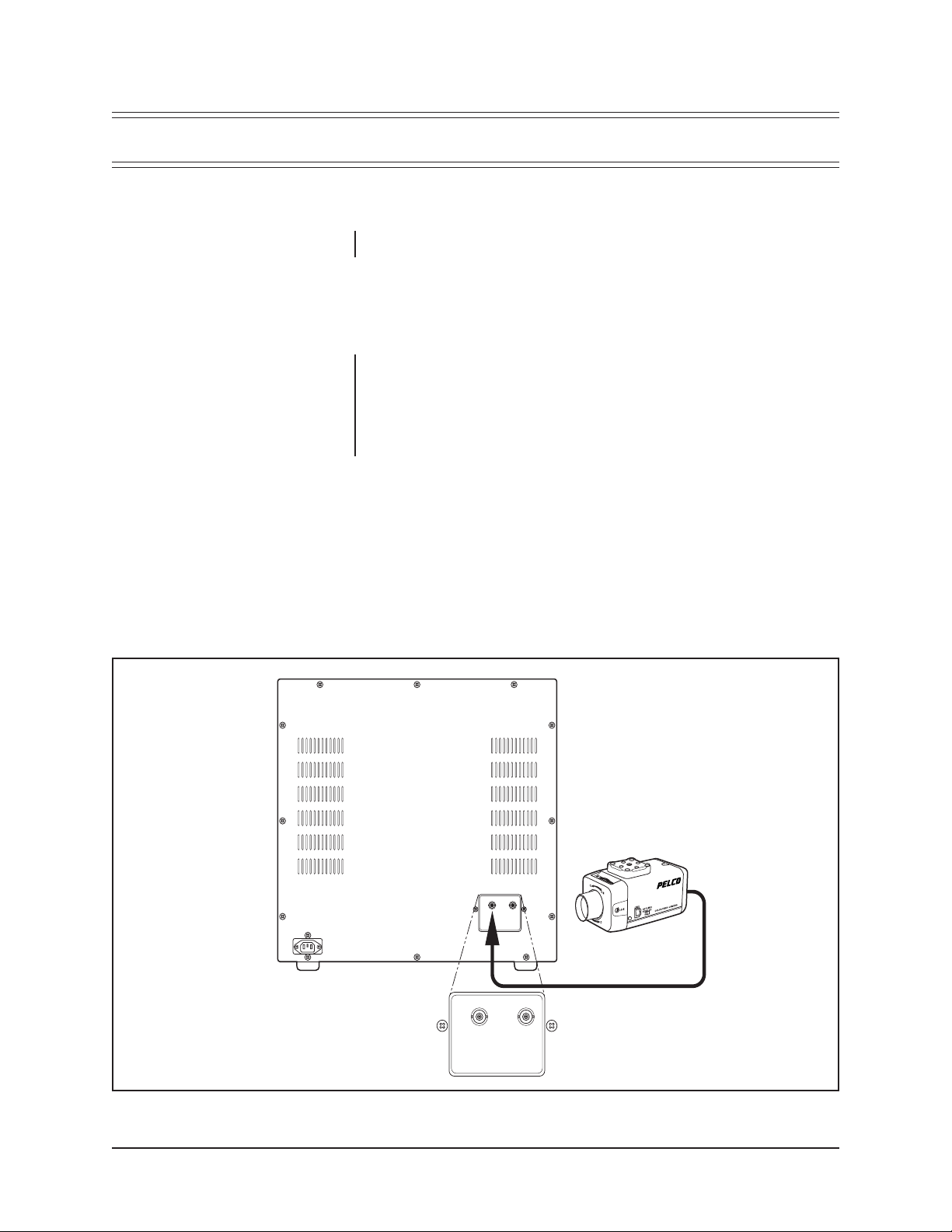
3.2.1 Single-Monitor Installation
Refer to Figure 1 and Table A for the following instructions.
1. Connect a 75-ohm video cable from the video source, such as a camera, to
the BNC connector labeled INPUT A on the back of the monitor.
2. Plug one end of the power cord into the back of the monitor and plug the other
end into a power outlet.
3.0 INSTALLATION
INPUT A OUTPUT A
INPUT A OUTPUT A
Figure 1. Single-Monitor Installation
Pelco Manual C935M (2/97) 5
Page 8

3.2.2 Multiple-Monitor Installation
NOTE:
In multiple-monitor installations, a maximum of three monitors can be connected together.
Refer to Figure 2 and Table A for the following instructions.
1. Connect a 75-ohm video cable from the video source, such as a camera, to
the BNC connector labeled INPUT A on the back of the first monitor.
2. Connect a 75-ohm video cable from the OUTPUT A connector on the back of
the first monitor to the INPUT A connector on the second monitor.
3. If you are using a third monitor, connect a 75-ohm video cable from the OUTPUT A connector on the back of the second monitor to the INPUT A connector on the third monitor.
4. For each monitor plug one end of a power cord into the monitor and the other
end into a power outlet.
Table A. Video Coaxial Cable Wiring Distances
Cable Type Maximum Distance
RG59 750 ft (229 m)
RG6 1,000 ft (305 m)
RG11 1,500 ft (457 m)
BRIGHT CONTRASTBRIGHT CONTRAST BRIGHT CONTRAST
FROM VIDEO
SOURCE TO INPUT
FROM OUTPUT
TO INPUT
FROM OUTPUT
TO INPUT
INPUT A OUTPUT A
REAR PANEL OF MONITOR
Figure 2. Multiple-Monitor Installation
6 Pelco Manual C935M (2/97)
Page 9

4.0 OPERATION
Refer to Figure 3 for the locations of the controls.
Power On/Off Switch - This rocker switch turns the power on or off. Push the side
with the white line to turn on the power. Push the side with the white circle to turn
the power off.
LED Power Indicator - The LED lights when power is turned on.
Brightness Control - This control adjusts the overall picture brightness to com-
pensate for differences in room lighting.
Contrast Control - This control adjusts the contrast between the black and white
portions of the picture. When properly adjusted, you will be able to observe a fine
gradation between blacks, grays, and whites.
To operate a monitor:
1. Make sure a standard 1.0 V peak-to-peak video signal is applied to the video
input of the monitor.
2. Press the power switch to turn on the power. The power indicator LED will
illuminate.
3. Adjust the brightness and contrast controls to obtain optimum picture quality.
BRIGHT CONTRAST
BRIGHTNESS
CONTRAST
POWER ON-OFF SWITCH
Figure 3. Location of Controls
Pelco Manual C935M (2/97) 7
Page 10

5.0 MAINTENANCE
The only maintenance required is to periodically clean the cabinet and screen.
Use a damp cloth to clean the screen.
Use mild soap and water to clean the cabinet. Some common household aerosol
sprays, cleaning agents, solvents, or polishes may damage the cabinet finish. Dry
the cabinet with a soft cloth.
8 Pelco Manual C935M (2/97)
Page 11

6.0 SPECIFICATIONS
ELECTRICAL
Input Voltage:
PMM2001 120 VAC, 60 Hz
PMM2001-X 230 VAC, 50 Hz
Power Consumption:
PMM2001
PMM2001-X 28 W
Input/Output Signal: 1 V peak-to-peak composite video signal
Input/Output Impedance: 75 ohms
Horizontal Resolution:
Center 1,000 lines
Corners 700 lines
Overscan: <10%
Linearity: <5%
Operating System:
EIA
Horizontal: 15,750 Hz ±400 Hz
Vertical: 60 Hz
CCIR
Horizontal: 15,625 Hz ±400 Hz
Vertical: 50 Hz
GENERAL
Environment: Indoor
Construction: Steel cabinet with black plastic front
Finish: Black matte texture coat finish
Dimensions:
PMM2001,
PMM2001-X 19.1" W x 18.5" H x 14.0" D
Picture Tube Dimension:
PMM2001,
PMM2001-X 20" (50.8 cm), measured diagonally
Operating
Temperature: 14° to 104° F (-10° to 40° C)
Humidity: Below 80%, relative
Weight:
Unit
PMM2001,
PMM2001-X 39.7 lbs (18 kg)
Shipping
PMM2001,
PMM2001-X 44.1 lbs (20 kg)
(48.5 cm x 47.0 cm x 35.5 cm)
Specifications subject to change without notice.
Pelco Manual C935M (2/97) 9
Page 12

7.0 WARRANTY AND RETURN INFORMATION
WARRANTY
Pelco will repair or replace, without charge, any merchandise proved defective in material or
workmanship for a period of one year after the date of shipment.
Exceptions to this warranty are as noted below:
Pelco, the Pelco logo, Camclosure, Esprit,
Genex, Legacy, and Spectra are registered
trademarks of Pelco.
Endura and ExSite are trademarks of Pelco.
© Copyright 1997, Pelco. All rights reserved.
• Five years on FT/FR8000 Series fiber optic products.
• Three years on Genex
• Three years on Camclosure
CC3751H-2, CC3651H-2X, MC3651H-2, and MC3651H-2X camera models, which have a fiveyear warranty.
• Two years on standard motorized or fixed focal length lenses.
• Two years on Legacy
dome products.
• Two years on Spectra
continuous motion applications.
• Two years on Esprit
• Eighteen months on DX Series digital video recorders, NVR300 Series network video
recorders, and Endura
• One year (except video heads) on video cassette recorders (VCRs). Video heads will be
covered for a period of six months.
• Six months on all pan and tilts, scanners or preset lenses used in continuous motion applications
(that is, preset scan, tour and auto scan modes).
Pelco will warrant all replacement parts and repairs for 90 days from the date of Pelco shipment.
All goods requiring warranty repair shall be sent freight prepaid to Pelco, Clovis, California. Repairs
made necessary by reason of misuse, alteration, normal wear, or accident are not covered under
this warranty.
Pelco assumes no risk and shall be subject to no liability for damages or loss resulting from the
specific use or application made of the Products. Pelco’s liability for any claim, whether based on
breach of contract, negligence, infringement of any rights of any party or product liability, relating
to the Products shall not exceed the price paid by the Dealer to Pelco for such Products. In no event
will Pelco be liable for any special, incidental or consequential damages (including loss of use, loss
of profit and claims of third parties) however caused, whether by the negligence of Pelco or
otherwise.
The above warranty provides the Dealer with specific legal rights. The Dealer may also have
additional rights, which are subject to variation from state to state.
If a warranty repair is required, the Dealer must contact Pelco at (800) 289-9100 or (559) 292-1981
to obtain a Repair Authorization number (RA), and provide the following information:
1. Model and serial number
2. Date of shipment, P.O. number, Sales Order number, or Pelco invoice number
3. Details of the defect or problem
If there is a dispute regarding the warranty of a product which does not fall under the warranty
conditions stated above, please include a written explanation with the product when returned.
Method of return shipment shall be the same or equal to the method by which the item was received
by Pelco.
RETURNS
In order to expedite parts returned to the factory for repair or credit, please call the factory at (800)
289-9100 or (559) 292-1981 to obtain an authorization number (CA number if returned for credit,
and RA number if returned for repair).
All merchandise returned for credit may be subject to a 20% restocking and refurbishing charge.
Goods returned for repair or credit should be clearly identified with the assigned CA or RA number
and freight should be prepaid. Ship to the appropriate address below.
If you are located within the continental U.S., Alaska, Hawaii or Puerto Rico, send goods to:
If you are located outside the continental U.S., Alaska, Hawaii or Puerto Rico and are instructed
to return goods to the USA, you may do one of the following:
If the goods are to be sent by a COURIER SERVICE, send the goods to:
Service Department
Pelco
3500 Pelco Way
Clovis, CA 93612-5699
Pelco
3500 Pelco Way
Clovis, CA 93612-5699 USA
If the goods are to be sent by a FREIGHT FORWARDER, send the goods to:
Pelco c/o Expeditors
473 Eccles Avenue
South San Francisco, CA 94080 USA
Phone: 650-737-1700
Fax: 650-737-0933
®
Series products (multiplexers, server, and keyboard).
®
and fixed camera models, except the CC3701H-2, CC3701H-2X,
®
, CM6700/CM6800/CM9700 Series matrix, and DF5/DF8 Series fixed
®
, Esprit®, ExSite™, and PS20 scanners, including when used in
®
and WW5700 Series window wiper (excluding wiper blades).
™
Series distributed network-based video products.
10 Pelco Manual C935M (2/97)
 Loading...