

Page 1
INSTALLATION/OPERATION
®
DX2000 Data Hub
C698M-A (6/04)
Page 2

CONTENTS
Section Page
IMPORTANT SAFEGUARDS AND WARNINGS ..................................................................................... 4
UNPACKING INSTRUCTIONS .................................................................................................... 4
DESCRIPTION ..................................................................................................................................... 5
DATA HUB FRONT PANEL ..........................................................................................................5
DATA HUB REAR PANEL ............................................................................................................ 6
MODELS .................................................................................................................................... 7
SUPPORTED COMMUNICATION TYPES............................................................................................. 8
SETTING UP THE SYSTEM ................................................................................................................. 8
INSTALLATION .................................................................................................................................... 9
CONNECTING POS TERMINALS TO THE DATA PORT INPUTS ................................................. 9
CONNECTING ATMS TO THE DATA PORT INPUTS ................................................................... 9
CONNECTING DAISY-CHAINED DATA HUBS ........................................................................... 10
CONNECTING TO THE DX2000 DVR ........................................................................................ 10
CONNECTING POWER TO THE DATA HUB .............................................................................. 10
U.S. STANDARD .............................................................................................................. 10
EUROPEAN STANDARD .................................................................................................. 10
PROGRAMMING THE DX2000 DVR FOR USE WITH A DATA HUB ..................................................... 11
INSTALLATION AND PROGRAMMING EXAMPLES ............................................................................ 13
SIMPLE CONFIGURATION FOR TWO ATM OR POS DEVICES .................................................. 13
MINIMUM CONFIGURATION FOR 16 ATM OR POS DEVICES ................................................. 14
MAXIMUM CONFIGURATION USING EIGHT DATA HUBS ....................................................... 15
POWERING UP AND SYSTEM OPERATION STATUS .......................................................................... 16
SPECIFICATIONS ............................................................................................................................... 17
REGULATORY NOTICES ..................................................................................................................... 18
WARRANTY AND RETURN INFORMATION ......................................................................................... 19
2 C698M-A (6/04)
Page 3

LIST OF ILLUSTRATIONS
Figure Page
1 DX2000 Data Hub Front Panel .............................................................................................. 5
2 DX2000 Data Hub Rear Panel ............................................................................................... 6
3 Configuration for Two Devices ............................................................................................. 13
4 Associated Programming Configuration for Two Devices ................................................... 13
5 Configuration for 16 Devices ............................................................................................... 14
6 Associated Programming Configuration For 16 Devices ..................................................... 14
7 Configuration Using Eight Data Hubs .................................................................................. 15
8 Associated Programming Configuration Using Eight Data Hubs ........................................ 16
C698M-A (6/04) 3
Page 4
IMPORTANT SAFEGUARDS AND WARNINGS
Observe the following WARNINGS before installing and using this product.
1. Installation and servicing should be done only by qualified service personnel and conform to all
local codes.
2. Unless the unit is specifically marked as a NEMA Type 3, 3R, 3S, 4, 4X, 6, or 6P enclosure, it is
designed for indoor use only and it must not be installed where exposed to rain and moisture.
3. The installation method and materials should be capable of supporting four times the weight of
the unit.
The product and/or manual may bear the following marks:
This symbol indicates that dangerous voltage
constituting a risk of electric shock is present
within this unit.
RISK OF ELECTRIC SHOCK.
This symbol indicates that there are important
operating and maintenance instructions in the
literature accompanying this unit.
Please thoroughly familiarize yourself with the information in this manual prior to installation and
operation.
UNPACKING INSTRUCTIONS
CAUTION:
DO NOT OPEN.
Unpack and inspect all parts carefully. Save the shipping carton, boxes, and inserts. They are the
safest manner in which to make future shipments.
If an item needs to be returned to the factory for repair, consult the WARRANTY AND RETURN
section of this manual for instructions.
4 C698M-A (6/04)
Page 5
DESCRIPTION
The DX2000 Digital Video Recorder (DVR) can capture data from point-of-sale (POS) terminals and
automated teller machines (ATMs) through four data ports. DVR data ports 3 and 4 can be
connected to the DX2000 Data Hub. Each data hub lets you connect up to seven additional ATM or
POS devices to a DX2000 DVR.
The data hub delivers transaction data to the DX2000 over a single cable at a distance of up to
4,000 feet (1,219 m). The data hubs can be daisy-chained together (up to four per chain, for eight
total), providing flexibility in system installation while minimizing wire runs.
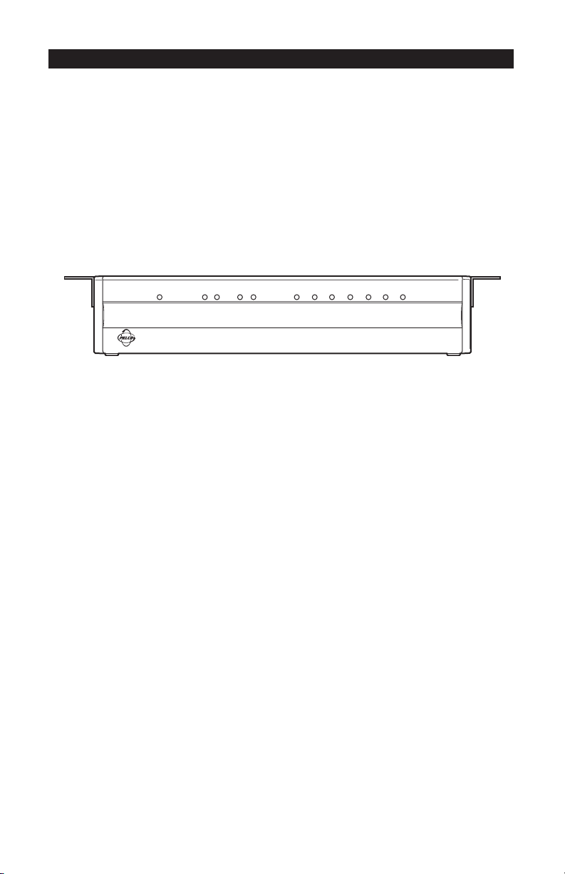
DATA HUB FRONT PANEL
POWER
HUB/PORT
OUT
IN
Tx Rx Tx Rx
1234567
DATA PORT
Figure 1. DX2000 Data Hub Front Panel
The indicators on the front panel show the following:
• Power Indicator
Lights to indicate the data hub has power.
• HUB/PORT Indicators
OUT
Tx: Lights when device data or data hub status information is transmitted to the DX2000 DVR.
Rx: Lights when configuration information is received from the DX2000 DVR.
IN
Tx: Lights when configuration information is transmitted to the next data hub in the daisy
chain.
Rx: Lights when device data or data hub status information is received from the next data hub
in the daisy chain.
• DATA PORT Indicators (1-7)
Light when data is received from the ATM or POS device connected to the specific port.
C698M-A (6/04) 5
Page 6
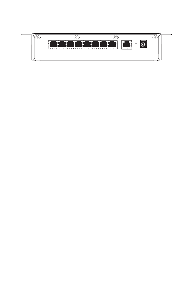
DATA HUB REAR PANEL
RESET
9-12V~
12 34 567IN
DATA PORT
HUB
OUT
DVR/HUB
Figure 2. DX2000 Data Hub Rear Panel
The rear panel contains the following:
• DATA PORT Input Connectors (1-7)
These ATM or POS device inputs connect to DX2000 data adapter or personality interface
module (PIM) cable (RJ-45 or RJ-11). Refer to the
Optional Compatible Products
• HUB IN Connector
This is used to connect to the next data hub in the daisy chain (farther from the DX2000 DVR)
using straight-pinned Cat5 cable with RJ-45 connectors.
• DVR/HUB OUT Connector
This is used to connect to the DX2000 DVR or the next data hub in the daisy chain using
straight-pinned Cat5 cable with RJ-45 connectors.
AC/DC
50/60hz
Use Only UL Listed
Class 2 Power Supply
section.
• RESET Button
Press this button to reset the data hub.
• AC/DC Power Connector
This is used to connect to the 12V power supply.
6 C698M-A (6/04)
Page 7

MODELS
DX2000DH DX2000 Data Hub, U.S. standard power supply (115V, 60Hz input, 12 VDC
output to data hub) and European standard power supply (230V, 50Hz input,
12 VDC output), FCC class B
The following are supplied:
Qty Description
1 DX2000DH
2 Mounting brackets (included for mounting under a counter or on a wall)
2 Power supplies (U.S. standard and European standard)
1 Power cord (U.S. standard)
1 Power cord (EU standard)
1 25-foot (7.6 m) straight-pinned Cat5 cable
Optional Compatible Products
RK101 DX2000DH rack mount kit
DX2000DA9 DB9 data adapter that connects directly to an ATM or POS device’s RS-232
output port (DB9)
DX2000DA9T DB9 “T” data adapter that connects to an ATM or POS device’s RS-232 output
port or existing RS-232 data cable (DB9)
DX2000DA25T DB25 “T” data adapter that connects to a POS device’s RS-232 output port or
existing RS-232 data cable (DB25). It connects an ATM’s RS-232 output port
or SNA network cable (DB25).
ICI1000PIM Data protocol translator used to interface with POS devices that lack RS-232
output ports. Refer to the ICI1000PIM Installation/Operation Manual
(C1005M) for POS devices supported.
C698M-A (6/04) 7
Page 8

SUPPORTED COMMUNICATION TYPES
Data Encoding Data Format Baud Rate Data Bits Parity Stop Bits*
Asynchronous NRZ ASCII 19200 8 None 1
SNA/SDLC NRZ EBCDIC 9600 7 Odd 2
SNA/SDLC NRZI 4800 Even
2400
1200
600
300
* Stop bits are selected automatically.
NOTE: Programming is done in the DX2000 system setup.
SETTING UP THE SYSTEM
You need to do the following to set up your system:
1. Rack mount the data hub(s) (if applicable).
2. Connect the devices as described in the Installation section.
3. Power up the data hub(s) (as described in the
4. Program the DX2000 as described in the
Hub
section.
5. Turn power on to units as described in the
8 C698M-A (6/04)
Connecting Power to the Data Hub
).
Programming the DX2000 DVR for Use with a Data
Powering Up and System Operational Status
section.
Page 9

INSTALLATION
Refer to the connection diagrams in the
illustrate and clarify the connection process.
Installation and Programming Examples
section. They help
CONNECTING POS TERMINALS TO THE DATA PORT INPUTS
POS terminals with RS-232 output ports are connected to the data hub using the DX2000 data
adapters (DX2000DA9 or DX2000DA9T for DB9 connectors and DX2000DA25T for DB25 connectors). Connect the data adapter to one of the data ports on the data hub using RJ-45 or RJ-11 cable.
Refer to the DX2000 Data Adapters Installation/Operation Manual (C697M) for detailed connection
information.
POS terminals without RS-232 output ports are connected to the data hub using the personality
interface module (PIM). Connect the PIM to one of the data ports on the data hub using RJ-45 or
RJ-11 cable. Refer to the ICI1000PIM Installation/Operation Manual (C1005M) for POS devices
supported and detailed connection information.
CONNECTING ATMS TO THE DATA PORT INPUTS
• SNA Network Connection
Connect the customer’s SNA network to the data hub using the DX2000DA25T Data Adapter.
Connect the data adapter to one of the data ports on the data hub using RJ-45 or RJ-11 cable.
Refer to the DX2000 Data Adapters Installation/Operation Manual (C697M) for detailed
connection information. (Refer to Figures 6 and 7.)
• ATM RS-232 Output Port Connection
Connect ATMs with RS-232 output ports to the data hub using the DX2000 data adapters
(DX2000DA9 or DX2000DA9T for DB9 connectors or DX2000DA25T for DB25 connectors).
Connect the data adapter to one of the data ports on the data hub using RJ-45 or RJ-11 cable.
Refer to the DX2000 Data Adapters Installation/Operation Manual (C697M) for detailed
connection information. (Refer to Figure 5.)
C698M-A (6/04) 9
Page 10

CONNECTING DAISY-CHAINED DATA HUBS
Up to four data hubs can be daisy-chained together. Connect the DVR/HUB OUT port of the next
data hub in the daisy chain (farther from the DX2000 DVR) to the HUB IN port on the data hub being
installed. Use straight-pinned Cat5 cable with RJ-45 connectors. (Refer to Figure 7.)
CONNECTING TO THE DX2000 DVR
Connect the DVR/HUB OUT port of the data hub to the DATA PORT input connector on the DX2000
DVR (you can use either port 3 or 4). Use straight-pinned Cat5 cable with RJ-45 connectors.
CONNECTING POWER TO THE DATA HUB
U.S. Standard
1. Connect the U.S. standard (120V, 60 Hz) power supply’s output connector to the data hub’s
power connector.
2. Plug the power supply into the proper power source.
European Standard
1. Connect the power cord to the European standard (230V, 50 Hz) power supply.
2. Connect the power supply’s output connector to the data hub’s power connector.
3. Plug the power cord into the proper power source.
10 C698M-A (6/04)
Page 11

PROGRAMMING THE DX2000 DVR FOR USE WITH A DATA HUB
You will need to program the following settings on the DX2000 DVR configuration screens to make
the data hub work properly.
Refer to the DX2000 Series Digital Video Recorder Installation/Operation Manual (C690M) for more
detailed programming information. Also refer to the programming screen examples in the
Installation and Programming Examples
Each data hub has seven ports to which data devices can be connected. Each data hub has an
eighth port (IN) that is used to daisy-chain to another data hub. The data hub’s ninth port (OUT) is
used to connect to the DX2000 DVR or to other data hubs. Up to four data hubs can be daisychained through data ports P3 and P4 of the DX2000 DVR, for a total of eight hubs.
The DX2000 can handle a maximum of 16 data inputs. You can select any combination of 16 total
data inputs from the 58 available ports (8 hubs total x 7 ports per hub = 56, plus 2 DX2000 data
ports = 58).
Do the following to program the DX2000 DVR for use with a data hub:
1. On your PC, call up Microsoft® Internet Explorer. Then, type the DVR’s IP address in the Address
box and press Enter. The Enter Network Password screen appears.
If the DVR’s IP address has been changed from the default (192.168.2.108:8004) and you do not
know this new IP address, you must obtain it from the network administrator.
NOTE: Port 80 is the standard web service (http) port. As an added network security measure,
port 8004 is the standard web service port for the DX2000. Therefore, any time you connect to
the DX2000 from your browser, you must add the 8004 port designation at the end of the
Internet address, proceeded by a colon (for example, http://192.168.2.108:8004). This is true for
any Internet address you choose to assign to the DX2000. Port 8004 is a fixed port number and
cannot be changed.
section. They will help clarify the programming process.
2. Type an administrative ID and password in the box, and then click the OK button. (The default
administrative ID is admin and the default administrative password is PELCOADM.) A
connection with the DX2000 is established.
3. Click the Configuration button. Click Data Interface.
C698M-A (6/04) 11
Page 12

4. On the Data Port Configuration tab screen, set up the DX2000 Data Hub. (Refer to the examples
in the
Installation and Programming Examples
section.)
You can select any of the seven ports on Hubs 1, 2, 3, and 4 as you wish. Multiple devices may
be assigned to the same port only if it is an ATM network connection. Non-network devices
may not be assigned to the same port.
To configure your data hub(s), do the following:
a. Use the pull-down menu to select Communication Type.
b. Enter a name for the data device in the Device Name box or accept the default.
c. Checkmark an Enable box to activate the data device.
d. Use the pull-down menu under DVR Port to select either P3Hub or P4Hub as the port on
the DVR to which the data hub will be connected.
e. Use the pull-down menu under Hub to select hub 1-4.
f. Use the pull-down menu under Hub Port to select port 1-7 on the data hub.
g. For ATM network connections, enter then hexadecimal device address in the Network
Address box.
h. Repeat steps a-g for each data device you want to assign.
5. Click the Save button to save this setup.
12 C698M-A (6/04)
Page 13

INSTALLATION AND PROGRAMMING EXAMPLES
The following examples show typical installations using the DX2000DH Data Hub. The input
devices (indicated by DATA DEVICE #) can be a POS terminal, ATM, or ATM SNA network
connection using one of the DX2000 data adapters or the PIM. The associated DX2000 DVR
programming shows “Standard Printer” as the communication type, which would be “ATM (SNA),”
“PIM,” or a custom communication type, depending on the actual device used.
SIMPLE CONFIGURATION FOR TWO ATM OR POS DEVICES
DX2000 DVR
1
D
A
T
2
A
P
O
3
R
T
S
4
Figure 3. Configuration for Two Devices
DATA DEVICE 2
1234567IN
DATA PORT
HUB DVR/HUB
DATA DEVICE 14
HUB#
P4-1
RESET
9-12V~
AC/DC
50/60hz
OUT
Use Only UL Listed
Class 2 Power Supply
Figure 4. Associated Programming Configuration for Two Devices
C698M-A (6/04) 13
Page 14

MINIMUM CONFIGURATION FOR 16 ATM OR POS DEVICES
DX2000 DVR
1
D
A
T
2
A
P
O
3
R
T
S
4
1234567IN
DATA PORT
HUB DVR/HUB
Figure 5. Configuration for 16 Devices
HUB#
P4-1
RESET
9-12V~
AC/DC
50/60hz
OUT
Use Only UL Listed
Class 2 Power Supply
DATA DEVICE 16
DATA DEVICE 15
DATA DEVICE 14
DATA DEVICE 13
DATA DEVICE 12
DATA DEVICE 11
DATA DEVICE 10
DATA DEVICE 1
DATA DEVICE 2
1234567IN
DATA PORT
HUB DVR/HUB
HUB#
P3-1
RESET
9-12V~
AC/DC
50/60hz
OUT
Use Only UL Listed
Class 2 Power Supply
DATA DEVICE 9
DATA DEVICE 8
DATA DEVICE 7
DATA DEVICE 6
DATA DEVICE 5
DATA DEVICE 4
DATA DEVICE 3
Figure 6. Associated Programming Configuration For 16 Devices
14 C698M-A (6/04)
Page 15

MAXIMUM CONFIGURATION USING EIGHT DATA HUBS
DX2000 DVR
1
D
A
T
2
A
P
O
3
R
T
S
4
1234567IN
DATA PORT
DATA DEVICE 13
1234567IN
DATA PORT
DATA DEVICE 14
1234567IN
DATA PORT
DATA DEVICE 15
1234567IN
DATA PORT
DATA DEVICE 16
HUB DVR/HUB
HUB DVR/HUB
HUB DVR/HUB
HUB DVR/HUB
DATA DEVICE 1
DATA DEVICE 2
1234567IN
DATA PORT
HUB DVR/HUB
HUB#
P3-1
RESET
9-12V~
AC/DC
50/60hz
OUT
Use Only UL Listed
Class 2 Power Supply
DATA DEVICE 9
DATA DEVICE 8
HUB#
P4-1
RESET
9-12V~
AC/DC
50/60hz
OUT
Use Only UL Listed
Class 2 Power Supply
DATA DEVICE 7
DATA DEVICE 6
DATA DEVICE 5
DATA DEVICE 4
DATA DEVICE 3
HUB#
P4-2
RESET
9-12V~
AC/DC
50/60hz
OUT
Use Only UL Listed
Class 2 Power Supply
HUB#
P4-3
RESET
9-12V~
AC/DC
50/60hz
OUT
Use Only UL Listed
Class 2 Power Supply
HUB#
P4-4
RESET
9-12V~
AC/DC
50/60hz
OUT
Use Only UL Listed
Class 2 Power Supply
1234567IN
DATA DEVICE 10
1234567IN
1234567IN
HUB#
DATA PORT
DATA PORT
DATA PORT
P3-2
HUB DVR/HUB
HUB DVR/HUB
HUB DVR/HUB
DATA DEVICE 12
RESET
9-12V~
AC/DC
50/60hz
OUT
Use Only UL Listed
Class 2 Power Supply
HUB#
P3-3
RESET
9-12V~
AC/DC
50/60hz
OUT
Use Only UL Listed
Class 2 Power Supply
HUB#
P3-4
RESET
9-12V~
AC/DC
50/60hz
OUT
Use Only UL Listed
Class 2 Power Supply
DATA DEVICE 11
Figure 7. Configuration Using Eight Data Hubs
C698M-A (6/04) 15
Page 16

Figure 8. Associated Programming Configuration Using Eight Data Hubs
POWERING UP AND SYSTEM OPERATION STATUS
When you apply power to the data hub or press the reset button, the front panel indicators provide
information about the data hub’s configuration. The information is flashed on hub data port
indicators 1-7 in the following order:
1. All data port indicators light to show a system reset occurred.
2. System revision is displayed through the numbered hub data port indicators that are lit.
3. The indicator for each data port lights to show that port has received the proper configuration
from the DX2000 DVR.
During normal operation, the data hub transmits a status message to the DX2000 DVR every three
seconds. The HUB/PORT OUT transmit indicator lights during each status message.
The reset button functions like disconnecting the power cord. You can press the button if for some
reason you want the unit to restart. Data will not be recorded until the unit completes its self test.
16 C698M-A (6/04)
Page 17

SPECIFICATIONS
ELECTRICAL
Input Power: 9-12V AC/DC, 500 mA, 3.6W
Power Supply: U.S. Standard (115V, 60 Hz)
European Standard (230V, 50 Hz)
MECHANICAL
Input/Output Connectors: RJ-45 standard
Power Connector: 2.3 mm center pin, 6 mm output diameter
GENERAL
Operating
Temperature Range: 32°-122° F (0°-50° C)
Dimensions: 8.75 (W) x 4.75 (D) x 2.00 (H) inches (22.23 x 12.07 x 5.08 cm)
Unit Weight: 2 lb (0.9 kg)
CERTIFICATIONS
DX2000DH
• CE, Class B
• UL Listed
• UL Listed to Canadian safety standards
• FCC, Class B
C698M-A (6/04) 17
Page 18

REGULATORY NOTICES
This equipment has been tested and found to comply with the limits of a Class B digital device,
pursuant to part 15 of the FCC rules. These limits are designed to provide reasonable protection
against harmful interference in a residential installation. This equipment generates, uses, and can
radiate radio frequency energy and, if not installed and used in accordance with the instructions, may
cause harmful interference to radio communications. However there is no guarantee that the
interference will not occur in a particular installation. If this equipment does cause harmful interference to radio or television reception, which can be determined by turning the equipment off and on,
the user is encouraged to try and correct the interference by one or more of the following measures:
• Reorient or relocate the receiving antenna.
• Increase the separation between the equipment and the receiver.
• Connect the equipment into an outlet on a circuit different from that to which the receiver is
connected.
• Consult the dealer or an experienced radio/TV technician for help.
18 C698M-A (6/04)
Page 19

PRODUCT WARRANTY AND RETURN INFORMATION
WARRANTY
Pelco will repair or replace, without charge, any merchandise proved defective in material or workmanship for a period of one year after the
date of shipment.
Exceptions to this warranty are as noted below:
• Five years on the following camera models: CC3701H-2, CC3701H-2X, CC3751H-2, CC3651H-2X, MC3651H-2, and MC3651H-2X.
• Three years on all fixed camera models (including Camclosure® Integrated Camera Systems) and Genex® Series (multiplexers, server, and
keyboard).
• Two years on all standard motorized or fixed focal length lenses.
• Two years on Legacy®, CM6700/CM6800/CM8500/CM9500/CM9700 Series Matrix, DF5 and DF8 Series Fixed Dome products.
• Two years on Spectra®, Esprit®, and PS20 Scanners, including when used in continuous motion applications.
• Two years on Esprit® and WW5700 series window wiper (excluding wiper blades).
• Eighteen months on DX Series digital video recorders and NVR300 network video recorders.
• One year (except video heads) on video cassette recorders (VCRs). Video heads will be covered for a period of six months.
• Six months on all pan and tilts, scanners or preset lenses used in continuous motion applications (that is, preset scan, tour and auto scan
modes).
Pelco will warrant all replacement parts and repairs for 90 days from the date of Pelco shipment. All goods requiring warranty repair shall be
sent freight prepaid to Pelco, Clovis, California. Repairs made necessary by reason of misuse, alteration, normal wear, or accident are not
covered under this warranty.
Pelco assumes no risk and shall be subject to no liability for damages or loss resulting from the specific use or application made of the
Products. Pelco’s liability for any claim, whether based on breach of contract, negligence, infringement of any rights of any party or product
liability, relating to the Products shall not exceed the price paid by the Dealer to Pelco for such Products. In no event will Pelco be liable for any
special, incidental or consequential damages (including loss of use, loss of profit and claims of third parties) however caused, whether by the
negligence of Pelco or otherwise.
The above warranty provides the Dealer with specific legal rights. The Dealer may also have additional rights, which are subject to variation
from state to state.
If a warranty repair is required, the Dealer must contact Pelco at (800) 289-9100 or (559) 292-1981 to obtain a Repair Authorization number
(RA), and provide the following information:
1. Model and serial number
2. Date of shipment, P.O. number, Sales Order number, or Pelco invoice number
3. Details of the defect or problem
If there is a dispute regarding the warranty of a product which does not fall under the warranty conditions stated above, please include a
written explanation with the product when returned.
Method of return shipment shall be the same or equal to the method by which the item was received by Pelco.
RETURNS
In order to expedite parts returned to the factory for repair or credit, please call the factory at (800) 289-9100 or (559) 292-1981 to obtain an
authorization number (CA number if returned for credit, and RA number if returned for repair).
All merchandise returned for credit may be subject to a 20% restocking and refurbishing charge.
Goods returned for repair or credit should be clearly identified with the assigned CA or RA number and freight should be prepaid. Ship to the
appropriate address below.
If you are located within the continental U.S., Alaska, Hawaii or Puerto Rico, send goods to:
Service Department
Pelco
3500 Pelco Way
Clovis, CA 93612-5699
If you are located outside the continental U.S., Alaska, Hawaii or Puerto Rico and are instructed to return goods to the USA, you may do one of
the following:
If the goods are to be sent by a COURIER SERVICE,
send the goods to:
Pelco
3500 Pelco Way
Clovis, CA 93612-5699 USA
® Pelco, the Pelco logo, Spectra, Genex, Legacy, Coaxitron, Esprit and Camclosure are registered trademarks of Pelco.
™ Spectra II and Spectra III are trademarks of Pelco.
© Copyright 2004, Pelco. All rights reserved.
If the goods are to be sent by a FREIGHT FORWARDER,
send the goods to:
Pelco c/o Expeditors
473 Eccles Avenue
South San Francisco, CA 94080 USA
Phone: 650-737-1700
Fax: 650-737-0933
REVISION HISTORY
Manual # Date Comments
C698M 6/02 Original version.
C698M-A 6/04 Per CAR 040407, added material to the manual indicating that port 8004 is now the standard web
C698M-A (6/04) 19
service port for the DX2000. This involves adding
:8004
to the end of the IP address.
Page 20

®
World Headquarters
3500 Pelco Way
Clovis, California 93612 USA
USA & Canada
Tel: 800/289-9100
Fax: 800/289-9150
International
Tel: 1-559/292-1981
Fax: 1-559/348-1120
www.pelco.com
ISO9001
Orangeburg, New York Las Vegas, Nevada Eindhoven, The Netherlands Wokingham, United Kingdom Montreal, Canada
20 C698M-A (6/04)
 Loading...