

®
BB5A/BB5L Series
Spectra™ Lite,
Spectra™
(Software Version 3.0)
and
Spectra II™ Domes
Back Box
Installation/
Operation Manual
C1488M-A (9/98)
U
®
L
LISTED
®
Pelco • 300 W. Pontiac Way, Clovis • CA 93612-5699 USA • Pelco Online @ http://www.pelco.com
In North America and Canada: Tel (800) 289-9100 or FAX (800) 289-9150 • DataFAX (800) 289-9108
International Customers: Tel (1-209) 292-1981 or FAX (1-209) 348-1120 • DataFAX (1-209) 292-0435

CONTENTS
Section Page
1.0 GENERAL..................................................................................................3
1.1 IMPORTANT SAFEGUARDS AND WARNINGS ...............................3
1.2 REGULATORY NOTICES ..................................................................4
1.3 UNPACKING INSTRUCTIONS ..........................................................5
1.4 RECOMMENDED TOOLS .................................................................5
2.0 DESCRIPTION ..........................................................................................6
2.1 MODELS............................................................................................6
2.2 CERTIFICATIONS .............................................................................6
3.0 INSTALLATION FOR IN-CEILING MODELS .............................................7
3.1 CEILING AND BACK BOX PREPARATION.......................................7
3.1.1 Hard Ceiling ...........................................................................7
3.1.2 Suspended Ceiling.................................................................8
3.2 WIRING .............................................................................................8
3.3 BACK BOX INSTALLATION..............................................................12
3.4 BACK BOX CONNECTIONS ............................................................13
4.0 INSTALLATION FOR PENDANT MODELS ..............................................15
4.1 PENDANT-MOUNT INSTALLATION .................................................15
4.2 SURFACE-MOUNT INSTALLATION .................................................15
5.0 TROUBLESHOOTING..............................................................................16
5.1 SERVICE MANUAL ..........................................................................16
6.0 SPECIFICATIONS .................................................................................... 17
7.0 WARRANTY AND RETURN INFORMATION ........................................... 20
LIST OF ILLUSTRATIONS
Figure Page
1 Back Box Parts ..................................................................................5
2 Compass Tool ....................................................................................7
3 Conduit Fitting Installation .................................................................7
4 Installing Back Box.............................................................................9
5 Fastening Back Box ...........................................................................9
6 Wiring Diagram for Spectra™ (Ver. 3.0) and Spectra II™.................10
7 Wiring Diagram for Spectra™ Lite ....................................................10
8 Interconnect Door .............................................................................12
9 Transformer Wiring............................................................................13
10 Interconnect Circuit Board Electrical Connections for
11 Interconnect Circuit Board for Spectra™ Lite ...................................14
12 SD5 Series Dimension Drawing........................................................18
Spectra™ (Ver. 3.0) and Spectra II™................................................13
LIST OF TABLES
Table Page
A Video Coaxial Cable Wiring Distances ..............................................8
B 24 VAC Wiring Distances ..................................................................11
REVISION HISTORY
Manual # Date Comments
C1488M 6/98 Original version.
C1488M-A 9/98 Rev A. Revised the manual to incorporate Spectra™
Lite material.
2 Pelco Manual C1488M-A (9/98)
1.0 GENERAL
1.1 IMPORTANT SAFEGUARDS AND WARNINGS
Prior to installation and use of this product, the following WARNINGS should be
observed.
1. Installation and servicing should only be done by qualified service personnel
and conform to all local codes.
2. Unless the unit is specifically marked as a NEMA Type 3, 3R, 3S, 4, 4X, 6, or
6P enclosure, it is designed for indoor use only and it must not be installed
where exposed to rain and moisture.
3. Only use replacement parts recommended by Pelco.
4. After replacement/repair of this unit’s electrical components, conduct a resistance measurement between line and exposed parts to verify the exposed
parts have not been connected to line circuitry.
5. The installation method and materials should be capable of supporting four
times the weight of the enclosure, pan/tilt, camera and lens combination.
The product and/or manual may bear the following marks:
This symbol indicates that dangerous voltage constituting a
risk of electric shock is present within this unit.
This symbol indicates that there are important operating and
maintenance instructions in the literature accompanying this
unit.
CAUTION:
RISK OF
ELECTRIC SHOCK.
DO NOT OPEN.
TO REDUCE THE RISK OF ELECTRICAL SHOCK,
DO NOT REMOVE COVER. NO USER-
SERVICEABLE PARTS INSIDE. REFER SERVICING
TO QUALIFIED SERVICE PERSONNEL.
CAUTION:
Please thoroughly familiarize yourself with the information
in this manual prior to installation and operation.
Pelco Manual C1488M-A (9/98) 3

1.2 REGULATORY NOTICES
NOTE: This equipment has been tested and found to comply with the limits of a
Class B digital device, pursuant to part 15 of the FCC rules. These limits are designed to provide reasonable protection against harmful interference in a residential installation. This equipment generates, uses, and can radiate radio frequency
energy and, if not installed and used in accordance with the instructions, may cause
harmful interference to radio communications. However there is no guarantee that
the interference will not occur in a particular installation. If this equipment does
cause harmful interference to radio or television reception, which can be determined by turning the equipment off and on, the user is encouraged to try and correct the interference by one or more of the following measures:
• Reorient or relocate the receiving antenna.
• Increase the separation between the equipment and the receiver.
• Connect the equipment into an outlet on a circuit different from that to which
the receiver is connected.
• Consult the dealer or an experienced radio/TV technician for help.
4 Pelco Manual C1488M-A (9/98)
1.3 UNPACKING INSTRUCTIONS
Unpack and inspect all parts carefully.
Be sure to save the shipping box and any inserts. They are the safest material in
which to make future shipments.
If an item appears to have been damaged in shipment, replace it properly in its box
and contact the factory at 1-800-289-9100 or 1-209-292-1981 for a replacement.
(International customers fax 1-209-348-1120 for authorization and instructions.)
If an item needs to be returned to the factory for repair, consult the WARRANTY
AND RETURN section of this manual for instructions.
The following items are supplied:
IN-CEILING MODELS
1 Back box
1 Installation/Operation Manual (C1488M)
1 Parts bag (refer to Figure 1)
1 Conduit fitting
1 Safety chain bracket
1 Lock nut
1 Compass tool
4 T-rail clip (clip, L-bracket, screw, lock washer, nut)
PENDANT MODELS
1 Back box
1 Tube of pipe sealant
1 Installation/Operation Manual (C1488M)
1.4 RECOMMENDED TOOLS
Pelco does not supply basic tools needed f or the installation process. The following
tools are recommended:
Small flat screwdriver
Coaxial cable stripper
BNC crimp tool
Wire stripper
Wire cutter
Pen or pencil (in-ceiling models only)
Drill with 3/32-inch drill bit (in-ceiling models only)
Saw to cut hole in ceiling (in-ceiling models only)
Medium Phillips screwdriver (in-ceiling models and pendant surface-mount only)
Drill with hole saw (pendant surface-mount only)
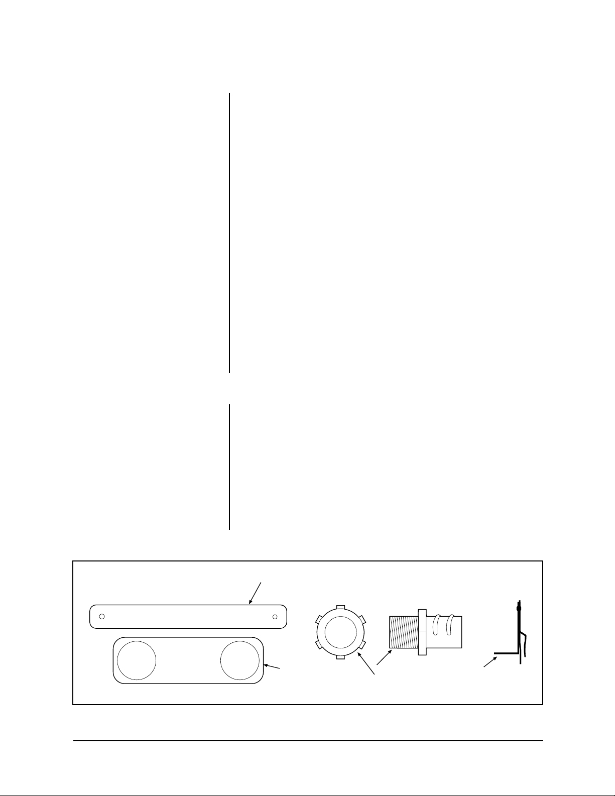
COMPASS TOOL
SAFETY
BRACKET
CONDUIT FITTING
& LOCK NUT
T-RAIL CLIP
Figure 1. Back Box Parts
Pelco Manual C1488M-A (9/98) 5
2.0 DESCRIPTION
The BB5A Series back boxes are used with the SD5 Series of Spectra™ (Software
Version 3.0) domes and SD5A Series of Spectra II™ domes . The BB5L Series back
boxes are used with the SD5L Series of Spectra™ Lite domes.
The BB5A-F and BB5L-F are for indoor installation in hard ceilings or standard 2' x 2'
(61 x 61 cm) suspended ceilings.
The BB5A-PB (black), BB5A-PG (light gray), and BB5L-PG (light gray) pendant
back boxes are for indoor installation. For outdoor use , the BB5A-PG-E and BB5LPG-E include a heater and sun shield. The heater allows oper ation in temperatures
down to -60°F (-51°C).
2.1 MODELS
BB5A-F Indoor back box for flush mounting in a ceiling
BB5A-PB Black pendant-mount back box
BB5A-PG Light gray pendant-mount back box
BB5A-PG-E Same as BB5A-PG except includes heater and sun shield
BB5L-F Indoor back box for flush mounting in a ceiling
BB5L-PG Light gray pendant-mount back box
BB5L-PG-E Same as BB5L-PG except includes heater and shield
2.2 CERTIFICATIONS
The products identified below have been tested and certified for agency compliance as noted.
Model CE FCC UL CSA/cUL
BB5A-F X X
BB5A-PB Pending Pending
BB5A-PG Pending Pending
BB5A-PG-E Pending Pending
BB5L-F
BB5L-PG
BB5L-PG-E
Applicable CE, FCC, UL, and CSA/cUL directives/standards:
• 93/68/EEC–CE Mark Directive
89/336/EEC, 92/31/EEC–Electromagnetic Compatibility (EMC) Directives
EN 55022: 1984 Class A–Radio-frequency emissions limits
EN 50082-2: 1992–Immunity standard
IEC 801-2: 1984–ESD immunity
IEC 801-3: 1984–Radiated field immunity
IEC 801-4: 1988–Electrical Transients
• FCC–47 CFR, Part 15, Subpart B, Class B
• UL Listed (DRQH) E119552
• cUL Listed (DRQH7)
Agency Compliance Certification
Additional applicable standards:
• NEMA Type 4 (except -F flush mount models; NEMA Type 1)
• IP 66 (except -F flush mount models; NEMA Type 10)
6 Pelco Manual C1488M-A (9/98)

CAUTION:
Be careful
not to cut outside of the
line. If y ou do, you ma y not
be able to install the back
box. Also, the trim ring
may not cover the hole.
3.0 INSTALLATION FOR IN-CEILING MODELS
This manual covers the installation of the BB5A-F, BB5A-PB, BB5A-PG, BB5A-PG-E,
BB5L-F, BB5L-PG, and BB5L-PG-E back boxes only. For complete installation and
operating instructions for the SD5 Series of Spectra™ (Software V ersion 3.0) domes,
refer to manual C1456M-D; for the SD5A Series of Spectra II™ domes and SD5L
Series of Spectra™ Lite domes, refer to manual C1487M-A.
3.1 CEILING AND BACK BOX PREPARATION
3.1.1 Hard Ceiling
1. Locate the center point where you want to drill a hole in the ceiling.
2. Drill a hole in the ceiling using a 3/32-inch drill bit.
3. Remove the compass tool from the parts bag (refer to Figure 2). Press the
stud of the compass tool into the hole in the ceiling. Insert a pencil in the hole
in the other end of the compass and mark a circle on the ceiling.
4. Carefully cut the circle out of the ceiling.
5. Remove the conduit fitting, lock nut, and safety chain bracket from the parts
bag and attach them to the back box as shown in Figure 3.
Proceed to Section 3.2, WIRING.
ATTACH SAFETY CHAIN HERE
Figure 2. Compass Tool Figure 3. Conduit Fitting Installation
Pelco Manual C1488M-A (9/98) 7

3.1.2 Suspended Ceiling
1. Remove the ceiling tile from the ceiling.
CAUTION:
The ceiling
tile must be capable of
supporting 16 pounds
(7.3 kg) of weight. If the
ceiling tile will not support
this weight, use the optional SD5-P metal panel.
CAUTION:
Be careful
not to cut outside of the
line. If y ou do, y ou may not
be able to install the back
box. Also, the trim ring
may not cover the hole.
2. Locate the center point to drill a hole in the tile.
3. Drill a hole in the ceiling tile using a 3/32-inch drill bit.
4. Remove the compass tool from the parts bag (refer to Figure 2). Press the
stud of the compass tool into the hole in the ceiling. Insert a pencil in the hole
in the other end of the compass and mark a circle on the ceiling.
5. Carefully cut the circle out of the ceiling tile.
6. Remove the conduit fitting, lock nut, and safety chain bracket from the parts
bag and attach them to the back box as shown in Figure 3.
7. Refer to Figure 4. Compress the spring clips on the back box with your hands
and push the back box through the hole in the ceiling tile. The spring clips will
spring out when they clear the ceiling tile.
8. Refer to Figure 5. Tighten the screws until the spring clips hold the back box
firmly to the ceiling tile. You will hear a clicking noise when the screws are tight.
Do not install the ceiling tile in the ceiling yet.
Proceed to Section 3.2, WIRING.
3.2 WIRING
Bring wiring to the back box opening in the ceiling. Do not attach the wiring to the
back box. You will do that later.
Refer to Figure 6 for the wiring diagram f or Spectr a™ (Version 3.0) and Spectra II™,
and to Figure 7 for the Spectra™ Lite.
NOTE:
The dome will stop operating if the voltage at the dome
drops below 18 VAC. It will turn
back on when the voltage exceeds
18 V A C.
Table A. Video Coaxial Cable
Wiring Distances
Cable Type* Maxim um Distance
RG59/U 750 ft (229 m)
RG6/U 1,000 ft (305 m)
RG11/U 1,500 ft (457 m)
* Minimum cable requirements:
75 ohms impedance
All-copper center conductor
All-copper braided shield with
95% braid coverage
Wiring is required for power, earth ground, and video.
Refer to Table A for the type of video coaxial cable to use.
Input power is 24 V A C only. Power consumption is 25 vA per dome f or indoor models
and 90 vA for outdoor models. Refer to Table B to determine the size of wire to use.
Use a 24 VAC transformer with the following minimum vA:
30 vA per dome For indoor models (without heater)
100 vA per dome For outdoor models (with heater)
Refer to Figure 9 for wiring multiple domes from the same transformer.
If you will use a Coaxitron® controller, the control signals to operate the dome drive
will be transmitted over the video coax. The RS-422 control lines are not used.
If you will not use a Coaxitron® controller, use the RS-422 control lines. Use 22-
gauge wire. The distance will be the same as the video coax.
Optional wiring may be provided for alarm inputs (maximum of sev en), relay output,
and auxiliary output.
Proceed to Section 3.3, BACK BOX INSTALLATION.
8 Pelco Manual C1488M-A (9/98)

HARD CEILING
OR
CEILING TILE
Figure 4. Installing Back Box
HARD CEILING
OR
CEILING TILE
T-RAIL CLIP
FOR
CEILING TILE
Figure 5. Fastening Back Box
T-RAIL CLIP
FOR
CEILING TILE
Pelco Manual C1488M-A (9/98) 9

CONTROL
(RS-422)
7
+5 to +24 VDC
EXTERNAL RELAY
(WIRING EXAMPLE)
Figure 6. Wiring Diagram for Spectra™ (Ver. 3.0) and Spectra II™
CONTROL
(RS-422)
Figure 7. Wiring Diagram for Spectra™ Lite
10 Pelco Manual C1488M-A (9/98)

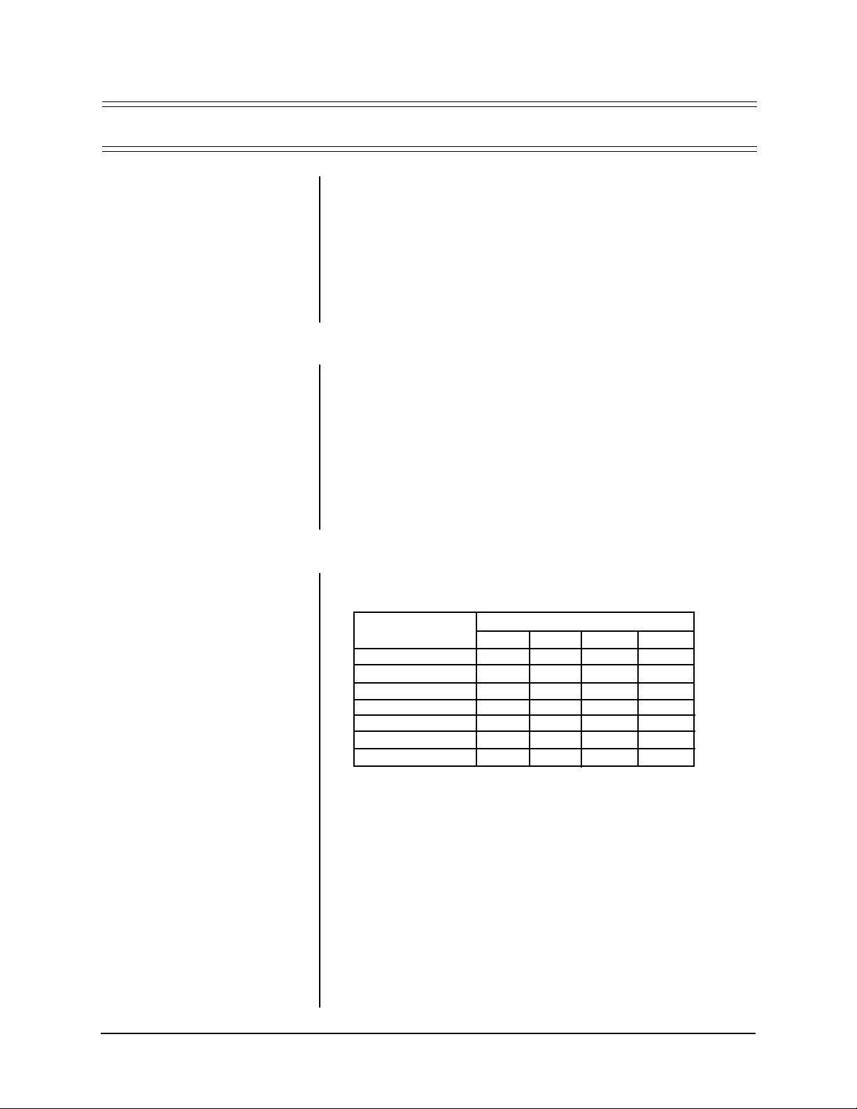
Table B. 24 VAC Wiring Distances
EXAMPLE:
A dome that requires
90 vA and is installed 31 feet (9 m)
from the transformer would require
a minimum wire gauge of 20 AWG.
NOTE:
Distances are calculated in
feet; values in parentheses are
meters.
The following are the recommended maximum distances for 24 VAC with a 10percent voltage drop. (Ten percent is generally the maximum allowable voltage drop
for AC-powered devices.)
Wire Gauge
20 18 16 14 12 10
10 283 451 716 1142 1811 2880
(86) (137) (218) (348) (551) (877)
20 141 225 358 571 905 1440
(42) (68) (109) (174) (275) (438)
25 113 180 286 457 724 1152
(34) (55) (87) (139) (220) (351)
30 94 150 238 380 603 960
(28) (45) (72) (115) (183) (292)
40 70 112 179 285 452 720
(21) (34) (54) (86) (137) (219)
50 56 90 143 228 362 576
(17) (27) (43) (69) (110) (175)
60 47 75 119 190 301 480
(14) (22) (36) (57) (91) (146)
70 40 64 102 163 258 411
(12) (19) (31) (49) (78) (125)
80 35 56 89 142 226 360
(10) (17) (27) (43) (68) (109)
90 31 50 79 126 201 320
(9) (15) (24) (38) (61) (97)
100 28 45 71 114 181 288
(8) (13) (21) (34) (55) (87)
110 25 41 65 103 164 261
Total vA consumed
(7) (12) (19) (31) (49) (79)
120 23 37 59 95 150 240
(7) (11) (17) (28) (45) (73)
130 21 34 55 87 139 221
(6) (10) (16) (26) (42) (67)
140 20 32 51 81 129 205
(6) (9) (15) (24) (39) (62)
150 18 30 47 76 120 192
(5) (9) (14) (23) (36) (58)
160 17 28 44 71 113 180
(5) (8) (13) (21) (34) (54)
170 16 26 42 67 106 169
(4) (7) (12) (20) (32) (51)
180 15 25 39 63 100 160
(4) (7) (11) (19) (30) (48)
190 14 23 37 60 95 151
(4) (7) (11) (18) (28) (46)
200 14 22 35 57 90 144
(4) (6) (10) (17) (27) (43)
Maximum distance from transformer to load
Pelco Manual C1488M-A (9/98) 11

3.3 BACK BOX INSTALLATION
OPTIONAL PROCEDURE:
If
you prefer, you may make the wiring connections inside the back box
before installing the back bo x in the
ceiling.
To do this, loosen the thumbscrew
inside the back box and open the
hinged door (refer to Figure 8).
Bring the wiring into the back box
through the conduit fitting. Follow
the steps in Section 3.4, “Back Bo x
Connections,” and then return to
this section.
CAUTION:
The ceiling
must be capable of supporting 16 pounds (7.3
kg) of weight. If the ceiling will not support this
weight, provide additional
reinforcement. Also, a
suitable safety chain must
be attached to the back
box to support up to 16
pounds (7.3 kg) in the
event of a ceiling failure.
1. Suspended Ceiling Only (for hard ceiling, go to step 2) – Install the ceiling
tile with the back box. Attach a T-rail clip on each side of the ceiling tile as
shown in Figure 5.
The clips for the ceiling tile are supplied with the back box. Attach the clip to
the T-rail. F asten the L-brac ket to the clip with the supplied scre w, lock washer
and nut.
2. Install a safety chain or cable (not supplied) that will support up to 16 pounds
(7.3 kg). F asten one end to a support structure in the ceiling. Fasten the other
end to the safety chain brack et (refer to Figure 3) to pre v ent the back bo x from
falling.
3. Refer to Figure 8. Loosen the thumbscrew inside the back box and open the
hinged door.
4. Bring the wiring into the back box through the conduit fitting. If the wiring is
inside flexible conduit, connect the conduit to the fitting on the back box.
5. Hard Ceiling Only - Refer to Figure 4. Compress the spring clips on the back
box with your hands and push the back bo x through the hole in the ceiling. The
spring clips will spring out when they clear the ceiling. Ref er to Figure 5. Tighten
the screws until the spring clips hold the back box firmly to the ceiling. Y ou will
hear a clicking noise when the screws are tight.
Proceed to Section 3.4, BACK BOX CONNECTIONS.
THUMBSCREW
Figure 8. Interconnect Door
12 Pelco Manual C1488M-A (9/98)

3.4 BACK BOX CONNECTIONS
Depending on the type of dome, refer to either Figure 10 or 11 to attach the wiring to the
interconnect circuit board inside the back box. Also refer to Figure 6 or 7 if necessary .
WARNING:
Make sure
you wire power to the
outer connectors of the
terminal block and ground
to the middle connector.
Otherwise, you could
damage the dome.
1. Earth Ground - Connect earth ground to the middle connector on the power
connector.
2. Power - Connect 24 VAC from the transformer to the outer terminals on the
power connector. It does not matter which lead goes to which terminal.
If you are wiring more than one dome from the same transformer, it is important to wire the power connector in each dome the same way. That is, the
wiring from one side of the transformer must be connected to the same connector on each dome. If you reverse the wiring, the cameras will be out of
phase with each other and may produce what appears to be vertical roll when
switching between cameras. Refer to Figure 9 for a wiring diagram.
3. Video - Connect the coaxial cable to the BNC video connector.
DOME 1
POWER
DOME 2
POWER
EXAMPLE:
requires 20 vA, three domes
require a 60 vA transformer.
If each dome
DOME 3
POWER
Figure 9. Transformer Wiring
CONNECTOR
FOR OPTIONAL
TRANSLATOR
SUBASSEMBLY
DOME DRIVE
CONNECTOR
FAN
RS-422
CONTROL
SIGNALS
AUX 1
(24 VA C ONL Y)
POWER
HTR/FAN
1
2
3
4
5
6
7
GND
NO
COM
NC
AUX 2
GND
PWR IN
ALARMS
RELAY
RX–
RX+
TX–
TX+
24 VAC
MIDDLE
PIN IS
GND
VIDEO
FUSE
1.6 A
Figure 10. Interconnect Circuit Board Electrical Connections for
Spectra™ (Ver. 3.0) and Spectra II™
Pelco Manual C1488M-A (9/98) 13

RS-422
CONTROL
SIGNALS
HTR/FAN
CONNECTOR
VIDEO
RX–
RX+
TX–
TX+
FOR OPTIONAL
TRANSLATOR
SUBASSEMBLY
DOME DRIVE
CONNECTOR
NOTE:
Connect only a low voltage device to the relay output.
Maximum current rating of the relay contacts is two amperes.
CAUTION:
The maximum output of AUX 2 is
150 mA. If you connect a
device that draws more
current, you could destroy
the output transistor. The
output is intended to drive
logic circuits or low-current
devices. If higher current
is required, connect the
output to a relay.
CAUTION:
Leave adequate slack in the wiring
to permit the door to open
without pulling on the connectors.
POWER
(24 VAC ONLY)
PWR IN
24 VAC
MIDDLE
PIN IS
GND
FUSE
1.6 A
FAN
Figure 11. Interconnect Circuit Board for Spectra™ Lite
4. Control - If you are using a Coaxitron® controller, control signals will be transmitted over the video coax.
If you are using RS-422 (P or D) control signals, connect the control lines from
the controller to the circuit board. Connect the wires as follows:
From controller To 4-Wire terminal on circuit board
RX- TX-
RX+ TX+
TX- RX-
TX+ RX+
5. Heater/Fan - The heater/fan is not used on indoor models.
6. Alarm Inputs - (Spectra™ [Ver sion 3.0] and Spectra II™ Onl y) If y ou need
alarm inputs, connect them. The maximum number of alarm inputs is seven.
Refer to Figure 6 for a typical wiring example. Alarm inputs require a ground
signal through a contact closure, such as a switch.
7. AUX 1 - (Spectra™ [Version 3.0] and Spectra II™ Only) An AUX 1 com-
mand from the controller will activate the relay output. If y ou need the relay, wire
it as required. Refer to Figure 6. The relay contacts are shown when AUX 1 is
inactive. When an A UX 1 command is issued, the rela y contacts will reverse and
remain latched until a clear command is issued.
8. AUX 2 - (Spectra™ [Version 3.0] and Spectra II™ Only) An A UX 2 command
from the controller will place a ground at the output of AUX 2 to operate the de vice
connected to it. The output will remain latched until a clear command is issued. If
you need the AUX 2 output, wire it as required. Refer to Figure 6 for typical wiring
examples. The A UX 2 output is an open collector transistor driver which is capable
of passing a maximum of 150 mA at 32 VDC. It is capable of driving TTL logic
circuits or low-current reed relays. If you use an e xternal relay , make sure that both
the supply voltage and the current requirements are well below the maximum of
32 VDC and 150 mA. Exceeding these values will cause permanent damage to
the dome. If you are not familiar with open collector drive requirements, contact
Pelco technical support for assistance.
9. Close the door and tighten the thumbscrew securely.
10. Turn on power to the back box. The red LED on the interconnect door should
light. The fan will not operate until a dome drive is installed.
If the LED does not light, correct the trouble before proceeding. Refer to Section 5.0, TROUBLESHOOTING.
14 Pelco Manual C1488M-A (9/98)

NOTE:
If outdoors, apply Duct
Seal inside the pipe portion of the
back box to prevent moisture or
cold air inside the mount from entering the unit and causing condensation on the dome. Duct Seal can
be purchased through local electrical supply houses.
4.0 INSTALLATION FOR PENDANT MODELS
4.1 PENDANT-MOUNT INSTALLATION
1. Install the pendant dome mount. Refer to the instructions provided with the
mount. If the mount is outdoors, mak e sure it is properly sealed to k eep moisture out.
2. Bring the wiring for the dome through the mount. Refer to Section 3.2, WIRING.
3. Refer to Figure 8. Loosen the thumbscrew inside the back box and open the
hinged door.
4. Screw the back box into the mount as f ar as possib le and bring the wiring into
the back box. If outdoors, apply the provided pipe sealant to the threads on the
back box.
5. Attach the wiring to the back box. Ref er to Section 3.4, BA CK BO X CONNECTIONS. Hanging do wn from the bac k bo x is a short cable (the trim ring leash)
and a heater connector with two wires (outdoor units only). The leash and
heater wiring will be connected when the lower dome is installed.
4.2 SURFACE-MOUNT INSTALLATION
1. Use a hole saw to drill a hole in the ceiling where you want to hang the pendant dome.
2. Bring the wiring for the dome to the opening. Refer to Section 3.2, WIRING.
3. Refer to Figure 8. Loosen the thumbscrew inside the back box and open the
hinged door.
4. Remove the gasket and the top mount from the back box by taking out the
three screws and lock washers.
5. Attach the back box to the ceiling using #8 hardware (not supplied). Reattach
the cable (trim ring leash) that was attached to one of the screws you remov ed
in step 4.
6. Attach the wiring to the back box. Ref er to Section 3.4, BA CK BO X CONNECTIONS. Hanging do wn from the bac k bo x is a short cable (the trim ring leash)
and a heater connector with two wires (outdoor units only). The leash and
heater wiring will be connected when the lower dome is installed.
Pelco Manual C1488M-A (9/98) 15

5.0 TROUBLESHOOTING
Symptom: LED does not light.
If the red power LED on the door of the interconnect circuit board in the back box
does not light:
1. Turn off power.
2. Open the door to the interconnect circuit board and check the fuse. Refer to
Figure 10 for the location of the fuse. If the fuse is bad, replace it. To order a
replacement fuse from Pelco , specify the part number FUS1.6-5X20FAST. This
is a 1.6-ampere fuse, 5 x 20 mm, fast blow.
3. If the fuse is good, turn on power and use a voltmeter to check if 24 VAC is
getting to the power connector on the interconnect circuit board. Refer to Figure 10 for the location of the AC power connector.
4. If there is 24 VAC to the power connector, turn off the power and return the
back box electronic assembly to the factory for repair.
To remove the back box electronic assembly:
a. Turn off power.
b. Open the interconnect door and disconnect all wiring to the back box.
c. Use an 11/32-inch socket driver to remove the three 8-32 washers and
nuts that hold the electronic assembly to the back box. When the screws
are removed, the interconnect back bo x receptacle will drop down. It may
be necessary to move the open interconnect door past 90° vertical toward the side of the back box to release the door from b uilt-in grounding
strip (and free the interconnect back box receptacle).
d. Remove the interconnect back bo x receptacle with the electronic compo-
nents from the back box.
5.1 SERVICE MANUAL
If you need to service your unit, obtain a service manual in on of the following wa ys:
• Go to Pelco’s web site at ftp://www.pelco.com and find service manual
C1455SM.
• Call Pelco’s DataFAX service at 1-209-292-0435 and request document
214558.
• Contact Pelco’ s Literature Department and request service manual C1455SM.
16 Pelco Manual C1488M-A (9/98)

6.0 SPECIFICATIONS
MECHANICAL
Construction
Back box: Aluminum
Cable Entry
In-Ceiling: .75" (1.91 cm) conduit fitting
Pendant: Through 1.5" (3.81 cm) NPT pendant mount
Dimensions: See Figure 12
ELECTRICAL
Input Voltage: 18-30 VAC, 24 VAC nominal
Input Power
In-ceiling: 25 vA
Indoor pendant: 25 vA
Outdoor pendant: 90 vA
Fuse: 1.6 A
Relay
Contacts (AUX 1)*
Type: Form C
Voltage: Low voltage (< 40 v)
Current: 2 A maximum
AUX 2 Output*
Type: Open collector transistor output
Voltage: 32 VDC maximum
Current: 150 mA maximum
* Applies to Spectra™ (Version 3.0) and Spectra II™ only.
GENERAL
Environment
In-Ceiling: Indoor only
Pendant: Indoor/outdoor
Operating Range
In-Ceiling: 32° to 122°F (0° to 50°C)
Pendant
Without heater: 32° to 122°F (0° to 50°C)
With Heater*: -60° to 122°F (-51.11° to 50°C)
continuous operation; minimal icing
-50° to 122°F (-45.56° to 50°C)
continuous operation; prevents icing
-40° to 122°F (-40° to 50°C) continuous operation; de-ices
0.1" (2.5 mm) within 3 hours after power-up
Weight Unit Shipping
In-Ceiling
Back Box 2.6 lbs (1.18 kg) 4.0 lbs (1.81 kg)
Pendant
Back Box
*Assumes no wind chill factor; for detailed test conditions, contact Pelco.
†
Add 1.25 lbs (.57 kg) for outdoor models with sun shield and heater
†
2.85 lbs (1.28 kg) 5.0 lbs (2.27 kg)
(Design and product specifications subject to change without notice.)
Pelco Manual C1488M-A (9/98) 17

5.25
(13.34)
3.25
(8.26)
7.25 (18.13)
6.60 (16.76)
TOP PORTION OF BACK BOX
IS REMOVABLE FOR SURFACE
MOUNT APPLICATIONS
(21.64)
10.90
27.69
DOME IS SECURED
TO CEILING BY
MOUNTING BRACKET
8.52
6.75
(17.15)
5.83
(14.80)
5.90 (14.99)
8.25 (20.96)
5.90
(14.99)
In-Ceiling Dome Pendant Dome
NOTE: VALUES IN PARENTHESES ARE CENTIMETERS, ALL OTHERS ARE INCHES.
Figure 12. SD5 Series Dimension Drawing
18 Pelco Manual C1488M-A (9/98)

NOTES
Pelco Manual C1488M-A (9/98) 19

7.0 WARRANTY AND RETURN INFORMATION
WARRANTY
Pelco will repair or replace, without charge, any merchandise proved defective in
material or workmanship for a period of one year after the date of shipment. Exceptions to this warranty are as noted below:
• Three years on Genex™ Series (multiplexers, server, and keyboard).
• Two years on all standard motorized and fixed focal length lenses.
• Two years on Legacy®, Intercept®, PV1000 Series, CM6700/CM8500/CM9500/
CM9750/CM9760 Matrix, Spectra™, DF5 Series and DF8 Fixed Dome products.
• Two years on WW5700 series window wiper (excluding wiper blades).
• Two years on cameras.
• Six months on all pan and tilts, scanners or preset lenses used in continuous
motion applications (that is, preset scan, tour and auto scan modes).
Pelco will warranty all replacement parts and repairs for 90 days from the date of
Pelco shipment. All goods requiring warranty repair shall be sent freight prepaid to
Pelco , Clo vis , California. Repairs made necessary by reason of misuse, alteration,
normal wear, or accident are not cov ered under this warranty.
Pelco assumes no risk and shall be subject to no liability for damages or loss resulting from the specific use or application made of the Products. P elco’ s liability for an y
claim, whether based on breach of contract, negligence, infringement of any rights
of any party or product liability, relating to the Products shall not exceed the price
paid by the Dealer to Pelco f or such Products. In no e vent will P elco be liable f or any
special, incidental or consequential damages (including loss of use, loss of profit
and claims of third parties) however caused, whether by the negligence of Pelco or
otherwise.
®Pelco and the Pelco logo are
registered trademarks of Pelco.
©Copyright 1998, Pelco. All rights
reserved.
The above warranty provides the Dealer with specific legal rights. The Dealer may
also have additional rights, which are subject to variation from state to state.
If a warranty repair is required, the Dealer must contact P elco at (800) 289-9100 or
(209) 292-1981 to obtain a Repair Authorization number (RA), and provide the
following information:
1. Model and serial number
2. Date of shipment, P.O. number, Sales Order number, or P elco inv oice n umber
3. Details of the defect or problem
If there is a dispute regarding the warranty of a product which does not fall under
the warranty conditions stated above, please include a written e xplanation with the
product when returned.
Ship freight prepaid to: Pelco
300 West Pontiac W a y
Clovis, CA 93612-5699
Method of return shipment shall be the same or equal to the method by which the
item was received by Pelco.
RETURNS
In order to expedite parts returned to the factory for repair or credit, please call the
factory at (800) 289-9100 or (209) 292-1981 to obtain an authorization number (CA
number if returned for credit, and RA number if returned for repair). Goods returned
for repair or credit should be clearly identified with the assigned CA/RA number and
freight should be prepaid. All merchandise returned for credit may be subject to a
20% restocking and refurbishing charge.
Ship freight prepaid to: Pelco
300 West Pontiac W a y
Clovis, CA 93612-5699
20 Pelco Manual C1488M-A (9/98)
 Loading...