Pelco EH4018-1-2, EH4014-CP, EH4014-CH, BK4000, BK4024 User Manual

® |
EH4014/EH4018 Series |
Camera Enclosures |
Installation/Operation Manual |
C430M-E (1/95) |
PELCO • 3500 Pelco Way • Clovis, CA 93612-5699 • USA • www.pelco.com |
(800) 289-9100 or (1-559) 292-1981 • FAX (800) 289-9150 or (1-559) 292-3827 |
PELCO Manual C430M-E (1/95) |
13 |
|
|
TABLE OF CONTENTS |
|
Section |
|
Page |
|
1.0 |
WARNINGS ......................................................................................................................................... |
1 |
|
2.0 |
SCOPE ................................................................................................................................................. |
2 |
|
3.0 |
DESCRIPTION ..................................................................................................................................... |
2 |
|
|
3.1 |
MODELS ..................................................................................................................................... |
3 |
|
3.2 |
OPTIONS .................................................................................................................................... |
3 |
|
3.3 |
RECOMMENDED CABLE SIZE ................................................................................................. |
4 |
|
3.4 |
SPECIFICATIONS ...................................................................................................................... |
5 |
4.0 |
INSTALLATION .................................................................................................................................... |
6 |
|
|
4.1 |
CAMERA/LENS INSTALLATION ................................................................................................ |
6 |
|
4.2 |
HEATER KIT INSTALLATION ..................................................................................................... |
7 |
|
4.3 |
BLOWER KIT INSTALLATION .................................................................................................... |
7 |
|
4.4 |
INSTALLATION PROCEDURES ................................................................................................ |
8 |
|
4.5 |
SUN SHROUD INSTALLATION .................................................................................................. |
9 |
5.0 |
CARE AND MAINTENANCE ................................................................................................................ |
9 |
|
6.0 |
EXPLODED ASSEMBLY DIAGRAM/PARTS LIST ............................................................................. |
10 |
|
7.0 |
WARRANTY AND RETURN INFORMATION .................................................................................... |
11 |
|
|
|
LIST OF ILLUSTRATIONS |
|
Figure |
|
Page |
|
|
1 |
EH4014/EH4018 Dimension Drawing ..................................................................................... |
2 |
|
2 |
Heater Bracket and Blower Installation ................................................................................... |
7 |
|
3 |
Heater/Blower Wiring Diagram ................................................................................................ |
8 |
|
4 |
Sun Shroud Installation ........................................................................................................... |
9 |
|
5 |
EH4014/EH4018 Exploded Assembly Diagram ..................................................................... |
10 |
Pelco, the Pelco Logo, Camclosure, Esprit, Genex, Legacy, and Spectra are registered trademarks of Pelco. Endura and ExSite are trademarks of Pelco.
© Copyright 1995, Pelco. All rights reserved.
ii |
PELCO Manual C430M-E (1/95) |
REVISION HISTORY |
|
|
Manual # |
Date |
Comments |
C430M |
11/88 |
Original version. |
C430M |
4/90 |
Rev. A. Added EH4014-1/-2, EH4014/BR, EH4014/CH, |
|
|
EH4014/CP, EH4018-1/-2, and BK4000/BK4024 models. Fig- |
|
|
ure 2 revised to show current design. Sections 4.2.1 and |
|
|
4.2.2 revised to include new cable distances and heater kit |
|
|
installation procedures. Section 7 updated to include addi- |
|
|
tional hardware. |
C430M |
9/90 |
Rev. B. Manual revised to include Section 1.1 for the UL |
|
|
compliance and listing. |
|
11/90 |
Addendum issued for addition of 230 VAC models. |
C430M |
11/90 |
Rev. C. Sections 2.1 thru 2.4, 3.0, 4.2, 4.2.1, and Figures 2 |
|
|
and 3 revised to include the addition of 230 VAC models. |
C430M |
8/91 |
Rev. D. Sections 2.3, 2.4 and Figure 3 revised to include |
|
|
additional mounts; revised voltages, power consumption and |
|
|
cable distances; and revised wiring diagram for heater/blower. |
|
1/93 |
Addendum issued to include installation instructions for out- |
|
|
door applications. |
C430M-E |
1/95 |
Rev. E. Revised to include new heater wattage values as |
|
|
per ECO #93-185, new component/assembly diagrams with |
|
|
updated BOM information as per ECO #93-187. Revised to |
|
|
show the removal of PC board when using blower kits only, |
|
|
with updated wiring diagrams, as per ECO #93-210. Incor- |
|
|
porated the use of CAPU0050.00/25 in 24 VDC blower kit |
|
|
wiring, as per ECO #94-447. Indoor/outdoor installation in- |
|
|
structions incorporated. |
|
9/95 |
Parts list updated to show revised number for item 13. |
PELCO Manual C430M-E (1/95) |
iii |
(This page intentionally left blank.)
iv |
PELCO Manual C430M-E (1/95) |

INSTALLATION/OPERATION MANUAL EH4014/EH4018 SERIES
CAMERA ENCLOSURES
1.0 WARNINGS
Prior to installation and use of this product, the following WARNINGS should be observed.
1. Installation and servicing should only be done by Qualified Service Personnel and conform to all Local codes.
2. Unless the unit is specifically marked as a NEMA Type 3-6P enclosure, it is designed for Indoor use only and it must not be installed where exposed to rain and moisture.
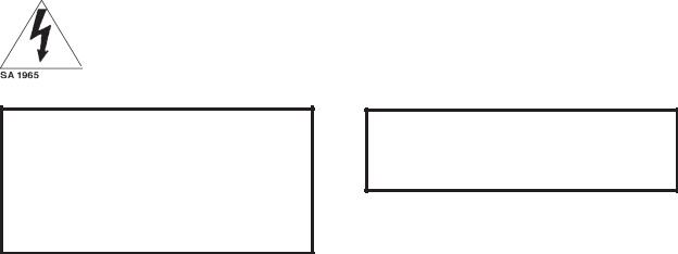
3. The product bears the following marks:
This symbol indicates that dangerous voltage constituting a risk of electric shock is present within this unit.
CAUTION:
TO REDUCE THE RISK OF ELECTRICAL SHOCK, DO NOT REMOVE COVER. NO USER-SERVICEABLE PARTS INSIDE. REFER SERVICING TO QUALIFIED SERVICE PERSONNEL.
4. Only use replacement parts recommended by PELCO.
5. After replacement/repair of this unit’s electrical components, conduct a resistance measurement between line and exposed parts to verify the exposed parts have not been connected to line circuitry.
6.The installation method and materials should be capable of supporting four (4) times the weight of the enclosure, pan/tilt, camera, and lens combination.
This symbol indicates that there are important operating and maintenance instructions in the literature accompanying this unit.
CAUTION:
RISK OF ELECTRIC SHOCK.
DO NOT OPEN.
Please thoroughly familiarize yourself with the information in this manual prior to installation and operation.
PELCO Manual C430M-E (1/95) |
1 |
 Loading...