

Page 1
FIUS1101G96
24V
USE AND CARE
UTILISATION ET ENTRETIEN
EN
FR
ES
EMPLEO Y MANUTENCION
GAUCHO
SUPERPOWER
Model Number IGOD0501US
See separate insert
sheet for more
information
Vea la hoja separada del
separador de millares
para másinformación
Voir ls feuille séparée
d’insertion pour plus
d’information
Requires 2 AA batteries (not included)
Requerir 2 AA baterías (no inclusa)
Exige 2 batteries de AA (ne pas inclus)
Page 2
SEE VERBAL
INSTRUCTIONS AFTER
THE PICTURES
VER LAS INSTRUCCIONES
DESPUÉS DE LOS DISEÑOS
VOIR LES INSTRUCTIONS
APRÈS LES DESSINS
ASSEMBLY
MONTAJE
MONTAGE
1
2 3
4
7
8 9
13
10
11
12
5
6
A
8
7
10
9
Page 3

22
21
28
18
23
15
A
14
19
20
16
17
24 25-6
27
B
A/B
C
A
B
A
1
2
3
Page 4

30
29
F
M/
O
N
O
F
F
A
M/
O
N
MI
N
H
O
U
R
S
E
T
A
B
D
F
E
31
32
33
34
FULLFULL
EMPTYEMP
TY
RESERVERESERVE
35
R
36
R
37 38
D
R
T
U
N
E
O
F
F
O
N
-
V
O
L
+
S
E
T
H
R
M
I
N
M
P
3
1
2
4 3
1
2
REPLACING THE BATTERY
CAMBIO DE LA BATERÍA
REPLACEMENT DE LA
BATTERIE
REGULATING REAR BRAKE
RÉGLAGE FREIN ARRIÈRE
REGULACIÓN DEL FRENO
POSTERIOR
VEHICLE FEATURES AND
INSTRUCTIONS FOR USE
CARACTERÍSTICAS Y USO
DEL VEHÍCULO
CARACTERÍSTIQUES ET
UTILISATION DU
VEHICULE
PARENTAL SPEED
CONTROL
CONTRÔLE PARENTAL DE
LA VITESSE
CONTROL DE VELOCIDAD
PATERNO
2
1
3
Page 5

39 40 41
42
43
44
B
C
BATTERY CHARGING
CARGA DE LA BATERÍA
CHARGE DE LA BATTERIE
4645
C
B
B
A
b = blue
bk = black
r = red
w = white
b = azul
bk = negro
r = rojo
w = blanco
b = bleu
bk = noir
r = rouge
w = blanc
ELECTRICAL DIAGRAM DIAGRAMA ELÉCTRICO DIAGRAMME ÉLECTRIQUE
GAUCHO SUPERPOWER cod.IGOD0501US
Page 6

GAUCHO SUPERPOWER cod. IGOD0501US
REPLACEMENT PARTS PIEZAS DE RECAMBIO PIÈCES DE RECHANGE
32
33
34
1
2
3
4
5
6
7
8
9
10
11
12
13
14
16
17
25
27
28
29
30
31
26
15
35
36
37
38
39
40
41
42
43
44
45
46
48
18
19
20
21
22
23
24
47
49
50
51
52
53
54
55
56
57
58
59
60
62
63
64
65
66
67
68
69
70
59
58
60
DECAL
CALCOMANIAS
DECALCOMANIES
61
1 SSPST9192N
2 SPST9193Y
3 SAGI9192NY
4 MMMO0151
5 ASGI0217NGP
6 SPST8767N
7 SPST0452N
8 SAGI0162N
9 SAGI0445JJGP
10 SAGI3822KGP
11 MEVA0050
12 SPST8235N
13 SAGI3029GR
14dx SAGI0127DM
14sx SAGI0127SM
15dx ASGI0054DN
15sx ASGI0054SN
16 ASGI0122NM
17 ASGI0024GP
18 ASGI0118GPGR
19 SPST8210N
20 SAGI0183GR
21 CSGAUC00-RI53
22 SAGI0321N
23 ASGI0043KGP
24 SPST3562N
25 SPST8749KN
26 SPST8750N
27 MUCI1012GRN
28 MUCI1009GR
29 SPST3867N
30 SPST3508N
31 SOFF0285Z
32 SPST3055A / RF
33dx SAGI8405KDNGR
33sx SAGI8405KSNGR
34 SPST3552N
35 SAGI0318KGP
36dx SPST3824DN
36sx SPST3824SN
37 SPST0315KN
38 ASGI0053A
39 IAKB0021US
40 SOPF0054L30
41 SAGI3263GPA
42 ASGI0135GPA
43 SPST0132
44 SAGI3821JM
45 SAGI0283L30
46 SPST8741N
47
SAGI8744KN
48 SPST3511R
49dx SPST3827DM
49sx SPST3827SM
50dx SPST3522DGP
50sx SPST3522SGP
51 SAGI8808XNGP
52 SPST3546N
53 SAGI8751KN
54 MMMV0035
55 SPST9143GL
56 SONF0050Z
57 SPST8936GL
58 SPST9255M
59dx SAGI8878WDN
59sx SAGI8878WSN
60 SPST8812N
61 MMEV0720
62 IKCB0111
63 SPST8768R
64 SAGI8762JNR
65 SAGI3510KXN
66dx SPST3507DGP
66sx SPST3507SGP
67 SPST3053M
68 SPST0316KN
69dx SPST3833DM
69sx SPST3833SM
70dx SPST3823DN
70sx SPST3823SN
Page 7

ENGLISH
PEG PEREGO®thanks you for choosing this product. For more than 60 years, PEG PEREGO have been taking children for an outing: first
with its famous baby carriages and strollers, later with its pedal and battery operated toy vehicles.
Discover our complete range of products, news and other information about the Peg Perego world on our web site www.pegperego.com
IMPORTANT INFORMATION
•Read this instruction manual carefully to learn the use of the vehicle and to teach your child safe and enjoyable
driving. Please keep this manual (with your original sales receipt) for use as a reference in the future.
•DO NOT RETURN YOUR VEHICLE TO THE STORE. This product cannot be returned for a refund
after it has been used. If you have ANY questions, need replacement parts or need assistance, call us
toll-free; U.S.A. , call 1-800-728-2108 / CANADA, call 1-800-661-5050
•This product meets and/or exceeds all ASTM (American Society for Testing and Materials) TOY SAFETY
STANDARDS, including F 963, Consumer Toy Safety Specifications as well as C.R.C, c.931, the Canadian Hazardous
Products (Toys)Regulations.
•Tools needed for assembly: medium phillips screwdriver and plyers.
•Your new vehicle is partially pre-assembled. It will require adult assembly. Please set aside at 45 minutes for assembly.
•Before the vehicle is used for the first time, charge the battery for 18 hours to initiate it. Failure to do this can result
in permanent battery damage.
•Use only with the included Peg Perego 24 Volt lead-acid, rechargeable battery and a Peg Perego 24 Volt Charger (both
included).
•Requires 2 “AA” batteries (not included) for operation of radio/clock:
•Year 3+
•Weight capacity 150 lbs
•Do not exceed the maximum total weight capacity of 150 lbs (68 Kg).
Contents:
•1 Gaucho Superpower ride-in vehicle -- partially assembled
•1 Rechargeable 24V 12Ah sealed lead-acid battery
•1 Charger 24V
•two 440 W motors -- pre installed
•1 FM radio with mp3 input (connection cord not included) -- pre installed
•assembly hardware
•parts to be assembled
•decals
•Speed in 1st gear 2,7 MPH - 4,5 Km/h
•Speed in 2nd gear 4,5 MPH - 7,2 Km/h
•Speed in 3rd gear 6,2 MPH - 10 Km/h
•Speed in reverse gear 4,5 MPH - 7,2 Km/h
•For safety, this vehicle has been pre-set so it will only operate in LOW speed. See step 34 to remove the HIGH speed
lock-out.
•To prevent damaging the motor and gears, teach your child to stop the vehicle before switching directions.
•Use this vehicle ONLY outdoors. Most interior flooring can be damaged by riding this vehicle indoors. Peg Perego will
not be respnsible for damage to the floor if the vehicle is used indoors.
•Peg Perego reserves the right to modify or change its products. Price, literature, manufacturing processes or locations
or any combination of the above mentioned entities may change at any time for any reason without notice with
impunity.
CAUTION:
ELECTRIC VEHICLE NOT RECOMMENDED FOR CHILDREN UNDER 3 YEARS OF AGE. AS WITH ALL ELECTRIC
PRODUCTS, PRECAUTIONS SHOULD BE OBSERVED DURING HANDLING AND USE TO PREVENT ELECTRIC
SHOCK. RECHARGER INCLUDED. 120 VOLTS, 60Hz, 33W INPUT, 24 VOLTS (DC) OUTPUT.
Page 8

CAUTION:
Only adults should recharge batteries never children.
Never allow children to handle batteries.
Only use the batteries specified by the manufacturer. Only use the charger specified by the manufacturer.
Do not mix old and new batteries.
Do not mix alkaline, standard (carbon-zinc), or rechargeable (nickel-cadmium) batteries.
CHARGING THE BATTERY
•Charge the batteries no longer than 24 hours, following the instructions enclosed with the battery charger.
•Charge the battery, as the vehicle shows low power, in this way you will avoid damage to the battery.
•If you don’t use your vehicle for a long period of time unplug the battery from the main wire harness of the
vehicle. Remember to charge the battery at least every three months.
•Never charge the battery upside down.
•Do not forget batteries during charging! Check them periodically.
•Never use a replacement recharger or batteries unless they are approved by PEG PEREGO.
•Batteries are sealed and maintenance free.
•Battery polarity must be observed when connecting battery to wiring.
WARNING:
•BATTERIES CONTAIN TOXIC AND CORROSIVE SUBSTANCES. DO NOT TAMPER WITH THEM.
•Batteries contain an acid-based electrolyte.
•Do not make direct contact between battery terminals, as this can cause an explosion or fire.
•Charging produces explosive gases. Charge batteries in a well ventilated area away from sources of heat and
flammable materials.
•Exhausted batteries are to be removed from the vehicle.
•Do not place the batteries near clothing to avoid damage.
IF A LEAK DEVELOPS
Shield your eyes. Avoid direct contact with the electrolyte, protect your hands.
Place battery in a plastic bag and follow directions listed below.
IF ELECTROLYTE COMES IN CONTACT WITH SKIN OR CLOTHING
Flush with cool water for at least 15 minutes.
See a physician at once.
IF ELECTROLYTE IS INJESTED
Give tap water, milk of magnesia or egg whites at once.
Do not induce vomiting.
See a physician at once.
DISPOSAL OF BATTERIES
Help protect the environment!
Do not throw used batteries in your regular, household trash.
Dispose of the old batteries in an approved dumping station; contact your local environmental protection agency
office for further information.
CAUTION AA BATTERIES
The insertion of batteries must only be carried out or supervised by adults. Do not let children play with the
batteries.
•The batteries should be replaced by an adult.
•Use only the type of battery specified by the manufacturer.
•Respect the polarity +/-
•Do not allow the batteries to be in contact with metal parts (risk of fire or explosion).
•Always remove the batteries if the toy is not in use for a long period.
•Never attempt to charge batteries that are not rechargeable.
•Remove dead batteries from the toy.
•Dispose of dead batteries into appropriate containers provided for their recycling.
BATTERY MAINTENANCE AND SAFETY
Page 9

CAUTION:
ADULT ASSEMBLY REQUIRED.
USE CARE WHEN UNPACKING AS COMPONENTS TO BE ASSEMBLED MAY POSE A SMALL PARTS/SHARP EDGE
HAZARD.
BATTERY ALREADY INSTALLED IN VEHICLE.
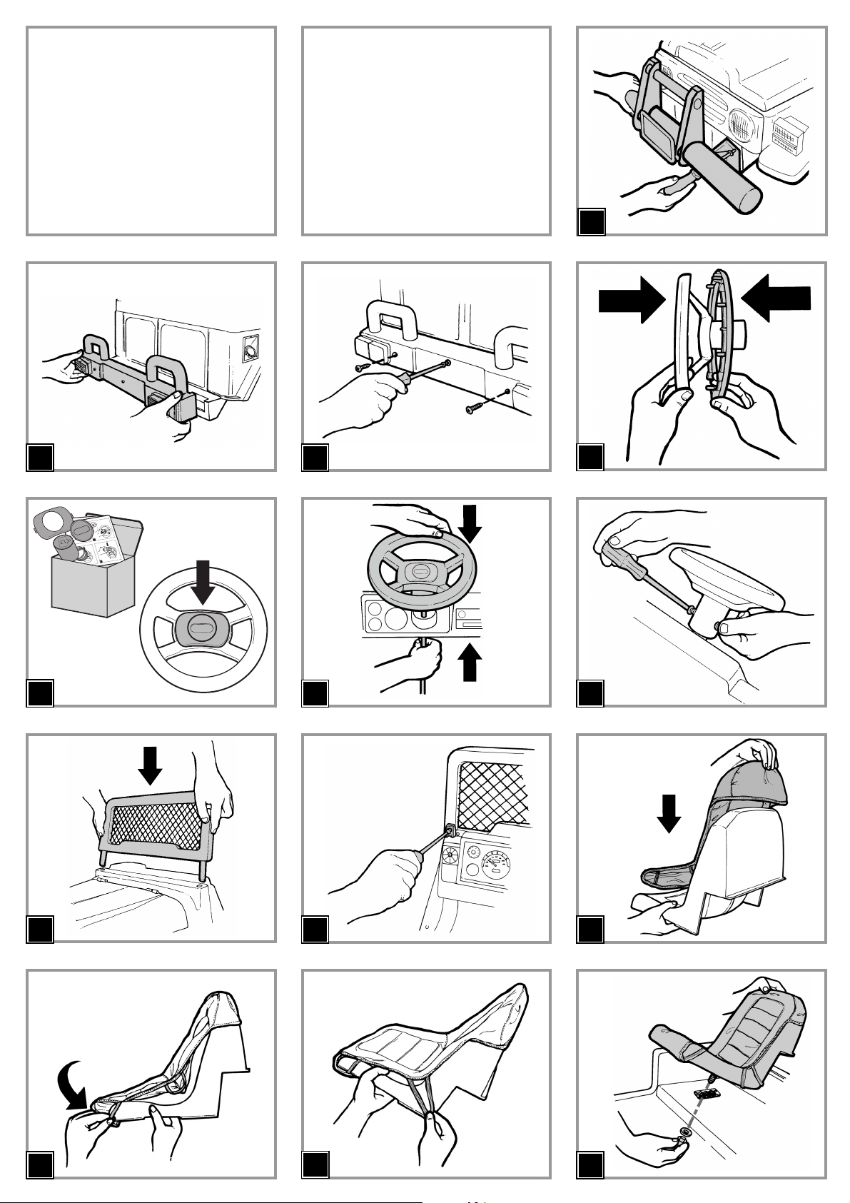
1 • Place from bumper on body and tighten four screws as shown in the drawing.
2 • Place rear bumper on body.
3 • Tighten three screws as shown in the drawing.
4 • Assemble the two parts of the steering wheel.
5 • Place the horn in the steering wheel’s central hole, following the instructions in its packaging.
6 • Insert the steering wheel on the steering wheel column.
7 • Align steering wheel column holes with steering wheel: nut fits into haxagon hole, bolt into round hole.
8 • Insert the windscreen.
9 • Secure it by means of the two screws.
10 •Fit the removable seat cover as shown in the figure.
11 •Hook the front elastic bands.
12 •Position the other two elastic bands.
13 •Place seat on body. Adjust seat position. Secure it with washer and thumb nut.
14 •Join A to part B of the Roll-Bar.
15 •Join A-B to the upper section of the Roll-Bar C, insert and rotate to secure.
16 •Insert the 2 plates in the slots at the base of the Roll-Bar and hold them in place. Secure the plates and the Roll-Bar with the 2 screws provided (detail A).
17 •Insert the end of the safety belt in the slot situated centrally in the bottom of the seat, as shown in the figure.
18 •Screw the net down to the body.
19 •Snap it around the roll-bar as shown in the drawing.
20 •Insert the rearview mirrors in the direction shown by the arrow.
21 •Place the 2 plastic signs, pressing down as you do so.
22 •Insert the antenna, pressing down as you do so, into its appropriate housing, situated on the right rear mudguard.
23 •Remove the radio from its packaging. Unscrew the cover from the battery chamber. Insert two 1.5 Volt AA batteries (not supplied with the vehicle) into the
compartment, taking care to position the positive and negative poles correctly. Close the battery compartment cover and screw into place.
24 •Insert the wire from the antenna and the radio into their appropriate housing on the dashboard, making sure to place them the right way up, as shown in the
figure.
25/6•Open the hood. Remove the two screws from the simulated engine. Remove the simulated engine. Proceed as follows:
- Remove the battery from the packaging;
- unscrew the battery block screw;
- position the battery;
- lock it down using the special battery block.
27 •Plug battery terminal A into vehicle wiring terminal B.
28 •Lower the imitation motor and screw it down again. Close the hood, securing it in place with the 2 hooks. The vehicle is now ready for use.
FEATURES AND INSTRUCTIONS FOR USE
29 •Hood support shaft.
30 •Below the box you can find four removable toy tools. To remove the box, pull out and unfasten the four couplings.
31 •A: HORN. Push the yellow button the horn will sound.
B: FM RADIO: a real removable car radio that works independently. Press button 3 to turn it on. Press button 4 to turn it off. Use the triangular buttons to
change the frequency with automatic tuning. The station will not be memorized when the radio is turned off. Use knob 2 to adjust the volume. To adjust the
time, hold down the SET button and push the HR and MIN buttons as appropriate.
The AUX (1) socket on the radio can be used for connecting MP3 devices.
D: ACCELERATOR PEDAL. To activate the vehicle’s driving wheels, press the accelerator pedal. N.B.: The speed of the vehicle increases when the accelerator
pedal is progressively pressed.
E: BRAKE PEDAL. The disk brakes are activated by pressing down on the brake pedal which will stop the vehicle.
F: PARKING BRAKE. The parking brake is activated by pressing the brake pedal and locking it in place with a special latch, see figure. To lock, lift the latch
located on the vehicle base all the way up and insert the pedal housing in it.
32 •To unfasten the safety belts:1 push towards the middle and simultaneously press the button; 2 detach the buckle.
33 •GEAR SHIFT LEVERS: GEAR SHIFT: D drive, R reverse.
34 •SECOND SPEED: SPEED REGULATION The vehicle is equipped with 3 speed adjustments:
1st speed 2,7 MPH - 4,5 Km/h
2nd speed 4,5 MPH - 7,2 Km/h
3rd speed 6,2 MPH - 10 Km/h
The speed selector is located inside the fuel cap (screwed shut), on the right rear side of the vehicle.
35 •DASHBOARD READING.
There are 2 lights which indicate the battery charge status on the dashboard:
GREEN LIGHT: indicates that the battery is charged and the vehicle may be used.
BLINKING GREEN LIGHT: indicates that the battery is on back up and recharging the vehicle is recommended.
RED LIGHT: indicates that the battery is flat and recharging is necessary to prevent jeopardizing functionality. As soon as the red light comes on the vehicle
turns off. It is possible to reactivate the vehicle which has 100 m of battery life to bring it to be recharged.
N.B. • At the time of ignition, both lights are activated for check-in.
• If the red light also comes on during correct driving function (green light), it is because the safety system which indicates that electrical parts are overheating
has been activated. In this case, the child must momentarily release the accelerator pedal.
REGULATING REAR BRAKE
Make sure that the vehicle is off before proceeding.
If rear brake pads are worn, regulation shall be carried out as follows:
36 •Press the tabs and pull out the 2 pins at the bottom of the engine, as shown in the figure.
37 •Keep the engine bottom open and unscrew the red knob (marked “R” in figure 36), then hold still the brake regulation ring and turn it clockwise by half a
notch. Next, tighten the red knob, close the engine bottom and reinsert the 2 rear pins, ensuring that they are in the same position as when they were
removed.
BATTERY REPLACEMENT
WARNING:
WARNING: BATTERY CHARGING AND ANY OTHER OPERATION ON THE ELECTRICAL SYSTEM MUST BE
CARRIED OUT BY ADULTS ONLY.
ASSEMBLY INSTRUCTIONS
INITIAL BATTERY CHARGE
!• Remove battery and charger from packaging. Connect battery charger to a 120vac wall recepticle. Connect battery charger to battery.
Page 10

For the safety of the child, before starting up the vehicle read and carefully follow the following instructions.
•Teach the child how to use the vehicle properly for safe and enjoyable driving.
•Before starting, check that there are no people or objects obstructing the vehicle’s path.
•Drive with hands on the handlebars/steering wheel and always watch the road ahead.
•Teach your child to step on the brake pedal to stop quickly to avoid collisions.
Parential SPEED CONTROL
It is recommended that beginners only use 1st gear until they become familiar with the safe operation of the
vehicle. To access faster speeds, parents can follow instruction # 34.
WARNING!
•Check wheel/axle nuts periodically to ensure they remain tight
•If the vehicle becomes overloaded as can happen on soft surfaces such as sand or mud, or steep inclines, the
overload switch will temporarily disconnect the power. If this happens, avoid driving on these surfaces.
•If the overload disconnect occurs while climbing a steep incline, the vehicle can roll backwards; To control the
speed of decent or to stop, instruct your child to remove their foot from the accelerator and step on the brake
pedal.
•On 12-Volt and 24 Volt vehicles: in 1st gear, the drive wheels have a differential effect like your car; on smooth
terrain, with a single child on board, the drive wheels can turn at different speeds; this is necessary for turning
and operating on slippery surfaces where one wheel will spin while the other wheel continues to achieve
traction. This will cause the vehicle to slow down momentarily.
LONGER DRIVING TIME: Purchase a spare battery to avoid Down Time when your initial battery requires
recharging.
RULES FOR SAFETY DRIVING
THE BATTERY CAN ALSO BE CHARGED WITHOUT REMOVING IT FROM THE VEHICLE.
38 •Open the hood. Remove the two screws from the simulated engine. Remove the simulated engine.
39 •Unscrew and remove the battery fastener.
40 •Replace the battery. Replace the battery fastener.
41 •Connect the two plugs.
42 •Replace simulated engine in vehicle and secure with screw.
BATTERY RECHARGE
43 •Disconnect the electrical unit plug A from the battery plug B by pressing at the sides.
44 •Insert the battery charger plug into a household outlet following the enclosed instructions. Connect plug B to battery charger plug C
45 •Once the battery has been recharged, unplug the battery charger from the wall outlet, then disconnect terminals C and B.
46 •Connect terminal B and A till you hear the final click. Once recharging is complete, don't forget to close the simulated motor with the screw.
Page 11

This product meets and/or exceeds all ASTM (American Society for Testing and Materials) TOY SAFETY
STANDARDS, including F 963, Consumer Toy Safety Specification.
This vehicle is not intended for use on streets, around traffic or parked cars.
MAINTENANCE AND CARE
•Regularly check the conditions of the vehicle, particularly the electrical system, the plug connections, the
covering caps and the charger. In case of fault, do not try to use the vehicle and the charger. For repair use only
original PEG PEREGO’s spare parts.
•PEG PEREGO assumes no liability if the electrical system is tampered with.
•Do not leave vehicle or batteries near sources of heat such as radiators, stoves, fireplaces, etc.
•Protect vehicle from water, rain, snow, etc.
•When operating in overload conditions, such as soft deep sand, mud or rough uneven terrain, the overload
circuit breaker will automatically disconnect the power. After 10 or more seconds,the circuit breaker will
automatically reset, however you must eliminate overload conditions to resume normal driving.
•Periodically lubricate (with a light weight oil) moving parts, such as wheel bearings, steering linkages, where they
rotate or touch one another.
•The vehicle’s surfaces can be cleaned with a dampcloth. Do not use abrasive cleaners. The cleaning must be
carried out by adults only.
•Never disassemble the vehicle mechanisms or motor unless authorized by PEG PEREGO.
SAFETY
WARNING:
•To reduce the risk of injury, adult supervision is required. Never use in roadways, near motor vehicles, on or
near steep inclines or steps, swimming pools or other bodies of water; always wear shoes, and never allow more
than 2 riders.
•Surfaces that are appropriate for safe use: grass, gravel, hard surfaces, slopes modarate.
•Not suitable for children under the age of 36 months. The small pieces could be swallowed or inhaled.
•Never use the vehicle on steep slopes or near steps or stairs. This vehicle is not suitable for use on public
highways.
•Children should always wear shoes when riding in or driving a riding vehicle.
•Do not allow children to place their hands, feet or any part of their body, clothing or other articles near the
moving parts while vehicle is in operation.
•Do not allow the electrical components, motors, wiring, switches of your motorized vehicle to become wet and
never wash it with a hose.
•Never use gasoline or other flammable substances near the vehicle.
•Please note that the seat belts are designed for play use only and DO NOT provide any protection.
VEHICLE MAINTENANCE AND SAFETY
Page 12

For your convience, PEG PEREGO offers after-sales service, directly or through a network of authorized service
centers for repairs or replacement parts.
If you have any questions about your Peg Perego vehicle, please call our toll-free service lines at;
U.S.A , call 1-800-728-2108
CANADA, call 1-800-661-5050
Trained customer service representatives are available to take your call in English or Spanish.
CUSTOMER SERVICE
IF THE VEHICLE DOES NOT OPERATE?
•When operating in overload conditions, such as running the vehicle against a fixed object, through
soft deep sand or mud, or over rough or uneven terrain, the overload circuit breaker will
automatically disconnect the power. After 10 or more seconds, the circuit breaker will
automatically reset, however-you must eliminate overload conditions to resume normal driving.
•Make sure that the battery is hooked up to the electrical unit.
•If the green LED does not come on after having properly carried out all the procedures:
1. Check the circuit board connector found on the dashboard (START).
2. Charge the batteries. If the problem persists after recharging, have the battery and battery charger checked by
a service centre.
•If the vehicle does not move when the accelerator pedal is pressed remember to:
1. Make sure that the brake pedal is not activated.
2. Check that the accelerator pedal’s steel wire is intact and that it is running properly.
•If the vehicle does not brake when the brake pedal is pressed remember to:
1. Regulate the brake pads.
2. Check that the brake pedal’s steel wire is intact and that it is running properly.
•Contact the Service Centre for any problem related to changing gears.
•The vehicle should never go forward by itself. If the contrary occurs, contact a service centre.
•If the red LED comes on when the vehicle is started contact a service centre.
•If it is difficult to move the steering wheel, we recommend greasing the steering bar (located underneath the
vehicle) and the wheel joints with grease or light oils.
•If the vehicle does not work in spite of all verifications, contact a service centre.
IF THERE IS NO POWER?
•Fully recharge the battery. If the problem persist, check with an Authorized PEG PEREGO Service Center.
PROBLEMS?
Page 13

ESPAÑOL
PEG PEREGO®le agradece que haya elegido esto producto. Hace más de 60 a os que PEG PEREGO lleva a pasear a los ni os: al nacer, con
sus famosos coches-cuna y coches de paseo, después con los fantásticos vehículos de juguete a pedal y con la batería.
Descubre la gama completa de los productos, las novedades y otras informaciones acerca del mundo Peg Perego en nuestra página Web
www.pegperego.com
INFORMACIÓN IMPORTANTE
•Lea este manual de instrucción cuidadosamente para aprender el uso del vehículo y para enseñar su conducir seguro
y agradable del niño. Guarde por favor este manual (con su recibo original de las ventas) para el uso como referencia
en el futuro.
•NO VUELA SU VEHÍCULO AL ALMACÉN. Este producto no se puede volver para un reembolso
después de que se haya utilizado. Si usted tenga los preguntas, necesita piezas de recambio o necesita
ayuda, llámenos gratis.
USA: 1-800-225-1558, MEXICO: 01-800-710-1369.
•Este producto cumple con y/o sobrepasa los ESTÁNDARES DE SEGURIDAD ASTM TOY, incluido el F 963,
Especificaciones de seguridad en juguetes para consumidores y C.R.C, c.931, el Regulaciones Peligrosas Canadienses
De los Productos (Juguetes).
•Herramientas necesitadas para el ensamblaje: destornilladores de la phillips medio y abrazaderas.
•Su vehículo nuevo se premonta parcialmente. Requiere a ensamblaje de un adulto. Puesto a un lado por favor por lo
menos 45 minutos para el ensamblaje.
•Antes de utilizar el vehículo por primera vez, cargar la batería durante 18 horas. No respectar este procedimiento
podría causar daños irreversibles a la batería, anulando su garantía.
•Utilice solamente con la clavija incluida Peg Perego 24 voltio baterías lead-acid, rechargables y una clavija Peg Perego
de 24 voltio cargadores (ambos incluidos).
• Requerir 2 “AA” baterías (no inclusa) para la operación de radio/clock.
•Años 3+
•Peso trasportable 150 lbs/68 Kg
•No exceda la capacidad total máxima del peso de 150 libras (68 Kg).
Contenido:
•1 Gaucho Superpower vehículo de los niños -- ensemblado parcialmente
•1 batería sellada recarable de plomo ácido de 24V 12Ah
•1 cargador de 24V
•2 motor de 440 W -- instalado previamente
•1 FM radio con la conexión para mp3 (cuerda de la conexión no incluida) -- instalado previamente
•dotacíon física del montaje
•piezas que se montaje
•calcomanias
•Velocidad en 1ª marcha 2,7 MPH - 4,5 Km/h
•Velocidad en 2ª marcha 4,5 MPH - 7,2 Km/h
•Velocidad en 3ª marcha 6,2 MPH - 10 Km/h
•Velocidad en marcha atrás 4,5 MPH - 7,2 Km/h
•Por motivos de seguridad, el vehículo se ha programado para que funcione a velocidad BAJA hasta que los padres
decidan si el niño tiene la capacidad y la habilidad necesarias para ir más rápido. Para acceder a las velocidades
mayores, por favor siga el punto 34.
•Para evitar el dañar de los motores y de los engranajes, enseñe a su niño a parar la dirección de la conmutación del
befor del vehículo.
•Utilice este vehículo al aire libre SOLAMENTE. La mayoría del suelo interior puede ser dañado montando este
vehículo dentro. Peg Perego no será responsable de daño al suelo si el vehículo se utiliza dentro
•Peg Perego se reserva el derecho de aportar modificaciones a sur productos. El precio, el manual adjunto, los
procesos o lugares de fabricación o una combinación de estos factores pueden provocar cambios sin previo aviso y
sin que ello suponga ninguna obligación para Peg Perego.
PRECAUTION:
LOS VEHICULOS ELECTRICOS NO SON RECOMENDABLE PARA NIÑOS MENORES DE 3 AÑOS. COMO TODOS
LOS PRODUCTOS ELECTRICOS, CUANDOO SE ESTA MANEJANDO OBSERVE LAS MEDIDAS DE PRECAUCION
PARA PREVENIR UN CHOQUE ELECTRICO. EL CARGADOR ESTA INCLUIDO. 120 VOLTS, 60 HZ, 33W DE
ENTRADA, 24 VOLTS (DC) DE SALIDA.
Page 14

ADVERTENCIAS:
Las baterías deben ser cargadas sólo por personas adultas.
No deje que los niños jueguen con las baterías.
Use sólo las baterías especificadas por el fabricante. Use solamente el cargador especificado por el fabricante.
No mezcle baterías viejas y nuevas.
No mezcle baterías alcalinas, estándar (carbono-zinc) o recargables (níquel - cadmio).
CARGA DE LAS BATERÍAS
•Cargar la batería siguiendo las instrucciones incluidas en el cargador y no superar en ningún caso las 24 horas.
No respetar estostiempos puede acortar la vida de las baterías.
•Cargue las baterías a tiempo, apenas el vehículo pierda velocidad. De este modo se evitarán otros daños.
•Si el vehículo se queda sin usarlo por largo tiempo, recuérdese de cargar la batería y de mantenerla
desconectada de la instalación; repita la operación de carga al menos cada tres mees.
•La batería no debe recargarse en posición invertida.
•¡No se olvide de las baterías que se están cargando! Contrólelas periódicamente.
•Use sólo el cargador en dotación y las baterías originales PEG PEREGO.
•Las baterías están selladas y no necesitan de mantenimiento.
•Inserte las baterías con la correcta polaridad.
ATENCÍON:
•LAS BATERÍAS CONTIENEN SUBSTANCIAS TÓXICAS CORROSIVAS.
NO SE DEBEN MANIPULAR ABUSIVAMENTE.
•Las baterías contiene electrolita de base ácida.
•No provoque el contacto directo entre los terminales de la batería, riesgo de explosión o incendio.
•Mientras se están cargando, las baterías producen gas explosivos. Cárguelas en un lugar bien ventilado, lejos de
fuentes de calor y materiales inflamables.
•Las baterías agotadas se deben sacar del vehículo.
•No coloque las baterías sobre prendas porque se podrían dañar.
SI HAY UNA PÉRDIDA
Protéjase los ojos. Evite el contacto directo con el electrolito: proteja sus manos.
Ponga la batería en una bolsa de plástico y siga las instrucciones para la eliminación de baterías.
SI PIEL Y OJOS ENTRAN EN CONTACTO CON EL ELECTROLITO
Lave abundantemente con agua corriente durante al menos 15 minutos.
Consultar un médico inmediatamente.
SI SE INGIERE ELECTROLITO
Tome pequeños sorbos de agua, leche de magnesia o clara de huevo.
No provocar el vómito.
Consultar un médico inmediatamente.
ELIMINACIÓN DE BATERÍAS
Ayude a proteger el medio ambiente.
Las baterías usadas no se deben tirar junto con la basura doméstica.
Se pueden entregar a un centro de recogida de baterías usadas o de eliminación de residuos especiales; infórmese
en su Ayuntamiento.
ADVERTENCIAS PILA AA 1,5 VOLTIOS
La colocación de la batería debe ser efectuada y supervisada sólo por adultos. No deje que los niños jueguen con
las baterías.
•La batería debe ser sustituida por un adulto.
•Utilizar sólo el tipo de pilas indicado por el fabricante.
•Respetar la polaridad +/-
•No poner en contacto las pilas con partes metálicas; riesgo de incendio o explosión.
•Retirar siempre la pila cuando el juguete no sea utilizado durante un largo periodo.
•No intentar cargar nunca las pilas si no son recargables.
•Quitar las pilas descargadas del vehículo.
•Tirar la pila descargada en los contenedores correspondientes para reciclaje de batería usadas
MANTENIMIENTO Y SEGURIDAD DE LA BATERÍA
Page 15

PRECAUTION:
REQUIERE MONTAJE DE UN ADULTO.
ALGUNOS COMPONENTES AL SER ENSAMBLADOS PODRÍAN TENER PARTES PEQUEÑAS/RIESGO POR
BORDES CONTANTES.
LA BATERÍA PODRÍA ESTAR INTRODUCIDA EN EL ARTÍCULO.
1 • Colocar el parachoques delantero y enroscar los cuantro tornillos.
2 • Colocar el parachoques posterior.
3 • Enroscar los tres tornillos como en la figura.
4 • Juntar las dos partes del volante.
5 • Introducir el claxon en el orificio central del volante siguiendo las instrucciones presentes en el embalaje.
6 • Insertar el volante en la barra del volante.
7 • Alinear los orificios de la barra del volante y del volante. Atornillar el tornillo y la tuerca: la turca se fija en el orificio hexagonal, el tornillo en el orificio circular.
8 • Insertar el perabrisas como en la figura.
9 • Enroscar los cuatro tornillos.
10 •Colocar el cubreasiento como en la figua.
11 •Sujetar los elasticos anteriores.
12 •Posicionar los 2 elasticos.
13 •Posicionar el asiento. Fijarlo con el tirante de arandela a la base.
14 •Acople la pieza A con la B.
15 •Acople A-B con la parte superiore de la barra cilindrica C, fijarla haciendola girar como en la figura.
16 •Insertar las 2 placas en los alojamientos de la base de la barra antivuelco sujetándolas. Atornillarlas a la barra antivuelco con los dos tornillos que se incluyen
(detalle A).
17 •Abrochar la hebilla de los cinturones de seguridad en la cavidad situada en la parte baja central del asiento, tal y como muestra la figura.
18 •Aplicar la red atornillándola primero al cuerpo de la máquina
19 •y después enganchándola a la barra cilíndrica.
20 •Insertar los espejos retrovisores en el sentido de la flecha.
21 •Aplicar los 2 letreros de plástico haciendo presión.
22 •Meter la antena presionando en su alojamiento en el guardabarros delantero derecho.
23 •Sacar la radio de su embalaje. Destornillar la tapa del compartimiento de las pilas. Meter dos pilas de tamaño AA de 1,5 V (no incluidas) en su alojamiento
respetando la polaridad correcta. Una vez terminada la operación, volver a cerrar la tapa del alojamiento de las pilas y volverla a atornillar.
24 •Meter el cable de la antena y la radio en el alojamiento del salpicadero en el sentido correcto, como muestra la figura.
25/6•Abrir el capó. Quitar los dos tornillos del falso motor. Levantar el falso motor. Luego seguir los pasos siguientes:
- sacar la batería del embalaje;
- quitar el tornillo del sujeta-batería;
- poner la batería;
- fijarla con el sujeta-batería.
27 •Introducir a fondo hasta el “clic” la clavija A e la clavija B.
28 •Bajar el motor simulado y volverlo a atornillar. Cerrar el capó asegurándolo con los 2 ganchos. El vehículo ahora ya está listo para usar.
CARACTERÍSTICAS Y USO DEL VEHÍCULO
29 •Astil de suporte del capó.
30 •Debajo de la maleta hay cuatro herramientas de juego que se pueden extraer. Para sacar la maleta, desenganchar las cuatro conexiones tirándolas hacia fuera.
31 •A: BOCINA. Apretando el botón amarillo se toca la bocina.
B: RADIO FM: una auténtica autoradio extraíble con funcionamiento autónomo.
Pulsar el botón 3 para encenderla y el botón 4 para apagarla. Utilizar los botones triangulares para cambiar la frecuencia con la búsqueda automática. La
estación no se queda memorizada al apagarse la radio. Utilizar la ruedecita 2 para ajustar el volumen. Para regular el reloj, mantener presionado el botón SET al
mismo tiempo que pulsa los botones HR y MIN según proceda.
La radio cuenta con una entrada AUX (1) para la conexión de dispositivos MP3.
D: PEDAL DEL ACELERADOR. Para accionar las ruedas motrices del vehículo, presionar el pedal del acelerador.
ATENCIÓN: presionando progresivamente el pedal del acelerador aumenta la velocidad del vehículo.
E: PEDAL DEL FRENO. Presionando el pedal, los frenos de disco entran en función deteniendo el vehículo.
F: FRENO DE ESTACIONAMIENTO. El freno de estacionamiento será accionado, por el papà, presionando el pedal del freno y bloqueándolo en su lugar con
un gancho especial, ver figura. Para su encaje, alzar el gancho, que se encuentra en la base del vehículo, hasta el final de la marcha e inserir la sede del pedal en
ésta.
32 •Para desenganchar los cinturones de seguridad: 1 empuje hacia el centro y contemporáneamente presione el pulsador; 2 desenganche el cinturón.
33 •PALANCA DE CAMBIO: D marcha, R marcha atrás.
34 •REGULACIÓN DE LA VELOCIDAD El vehículo tiene 3 regulaciones de marcha:
1° velocidad 2,7 MPH - 4,5 Km/h
2° velocidad 4,5 MPH - 7,2 Km/h
3° velocidad 6,2 MPH - 10 Km/h
El selector de la velocidad está situado dentro de la tapa del depósito de la gasolina (atornillado), en la parte posterior lateral derecha del vehículo.
35 •LECTURA DEL TABLERO
En el tablero aparecen 2 leds que indican el estado de carga de la batería:
LED VERDE: indica que la batería está cargada y se puede usar el vehículo.
LED VERDE INTERMITENTE: indica che la batería está en reserva y se aconseja recargar el vehículo.
LED ROJO: indica que la batería esta descargada y es necessario recargarla para no comprometer la funcionalidad. En el momento que se enciende la luz roja,
el vehículo se apaga. Es posible reencender el vehículo que dispone de 100 m de autonomía para llevarlo a recargar.
ATENCIÓN
•En el momento de que hace contacto los leds se accionan para el check in.
•Si durante el correcto funcionamiento de marcha (led verde), interviniera también el led rojo, sería debido a la activación de un sistema de seguridad causado
por el calentamiento de las partes eléctricas. En tal caso es necesario que le niño deje momentáneamente el pedal del acelerador.
REGULACIÓN DEL FRENO POSTERIOR
Antes de continuar asegurarse de que el vehículo no esté en funcionamiento.
En caso de desgaste de las pastillas del freno posterior, la regulación debe ser efectuada del siguiente modo:
36 •Extraer los 2 pernos del fondo del motor al mismo tiempo que se aprietan los dientes tal y como se muestra en la imagen.
37 •Con el fondo del motor abierto, desatornillar el pomo rojo (“R”, ver figura 36), sujetar el anillo de regulación del freno y girarlo media vuelta en el sentido de
las agujas del reloj. Volver a atornillar el pomo rojo, cerrar el fondo del motor e insertar de nuevo los 2 pernos posteriores en la misma dirección que antes.
SUSTITUCIÓN DE LA BATERÍA
INSTRUCCIONES DE MONTAJE
PRIMERA CARGA DE LA BATERÍA
!• Quite la batería y el cargador del empaquetado. Conecte el cargador de la batería con un socket doméstico.
Conecte el cargador de batería con la batería.
Page 16

Para la seguridad del niño: antes de accionar el vehículo, leer y seguir atentamente las siguientes instrucciones.
•Enseñar a su niño el uso correcto del vehículo para una conducción segura y divertida.
•Antes de partir, comprobar que el recorrido esté libre de personas o cosas.
•Conducir con las manos sobre el volante/manubrio y mirar siempre el camino.
•Enseñe a su hijo a pisar el pedal de freno para que se detenga rápidamente y evite colisiones.
CONTROL DE VELOCIDAD Paterno
Se recomienda que los principiantes utilicen sólo la primera marcha hasta que se familiaricen con el uso seguro del
vehículo. Para acceder a las velocidades mayores, los padres pueden seguir las instrucciones del punto 34.
¡ATENCIÓN!
•Compruebe periódicamente las tuercas de las ruedas y de los ejes para asegurarse de que siguen estando bien
apretadas.
•Si el vehículo se sobrecargase, como es posible que ocurra sobre superficies blandas como arena o barro, o en
pendientes empinadas, el interruptor de sobrecarga desconectará temporalmente la alimentación. Si esto
ocurriese, evite conducir sobre este tipo de superficies.
•Si la desconexión por sobrecarga se produjese subiendo una pendiente empinada, el vehículo podría rodar hacia
atrás. Enseñe a su hijo a quitar el pie del acelerador y a pisar el pedal de freno para controlar la velocidad
durante el descenso o parar.
•Vehículos de 12 volt y 24 volt: en la primera marcha, las ruedas motrices tienen un efecto diferencial, al igual que
su coche. Sobre terreno llano, y con sólo un niño a bordo, las ruedas motrices pueden girar a diferentes
velocidades, lo que es necesario para girar y rodar sobre superficies resbaladizas en las que una rueda gira
mientras la otra se agarra. Esto hará que el vehículo vaya más despacio momentáneamente.
MAYOR TIEMPO DE CONDUCCIÓN: Adquiera una batería de repuesto para evitar los tiempos muertos cuando
tenga que recargar la batería inicial.
REGLAS PARA CONDUCIR EN CONDICIONES DE SEGURIDAD
ATENCIÓN:
LA OPERACIÓN DE RECARGA DE LA BATERÍA ASÍ COMO CUALQUIER INTERVENCIÓN ELÉCTRICA,
DEBEN SER REALIZADAS ÚNICAMENTE POR PERSONAS ADULTAS.
LA BATERÍA TAMBIÉN SE PUEDE RECARGAR SIN QUITARLA DEL JUGUETE.
SÓLO PARA EL BRASIL: TENSIÓN DEL CARGADOR: 127V - 60 HZ. OBSERVACIÓN: NO UTILIZAR EL
CARGADOR DE LA BATERÍA CON UNA TENSIÓN DE 220V.
38 •Abrir el capó. Quitar los dos tornillos del falso motor. Levantar el falso motor.
39 •Desenrosque el tornillo y saque el sujetabateria.
40 •Cambie la batería. Vuelva a colocar y cerrar el sujetabatería.
41 •Conectar los dos enchufes.
42 •Cerrar atornillando el falso motor.
CARGA DE LA BATERÍA
43 •Desenchufar la toma A del implanto eléctrico de la toma B de la batería presionando lateralmente.
44 •Enchufar el cargabaterías a una toma doméstica siguiendo las instrucciones adjuntas. Conectar la toma B con la toma C del cargabaterías.
45 •Una vez acabada la carga, sacar el cargador de batería de la toma doméstica, después desconectar el enchufe C del enchufe B.
46 •Introducir a fondo, hasta que salte el mecanismo, el enchufe B en el enchufe A. Finalizada la operación recuerde siempre cerrar el falso motore atornillando el
tornillo.
Page 17

Este producto cumple con y/o sobrepasa los ESTÁNDARES DE SEGURIDAD ASTM TOY, incluido el F 963,
Especificaciones de seguridad en juguetes para consumidores.
Este vehículo no ha sido fabricado para ser usado en la vía pública, con vehículos en movimiento o aparcados.
MANTENIMIENTO Y CUIDADOS
•Controlare periódicamente el estado del vehículo, en especial la instalación eléctrica, las conexiones de los
enchufes, las caperuzas de protección y el cargador. En caso de defectos comprobados, el vehículo eléctrico y el
cargador no deben utilizarse. Para las reparaciones utilizar sólo piezas de recambio originales PEG PEREGO.
•PEG PEREGO no se asume ninguna responsabilidad en caso de uso indebido de la instalación eléctrica.
•No dejare las baterías o el vehículo cerca de fuentes de calor como radiadores, caloríferos, chimeneas, etc.
•Proteger el vehículo contra el agua, lluvia, nieve, etc.;
•Si el vehículo funciona en condiciones de sobrecarga, por ejemplo sobre arena blanda, barro o terrenos muy
accidentados, el interruptor de la sobrecarga desconectará inmediatamente la potencia. El suministro de
corriente se reanudará una vez eliminadas las condiciones de sobrecarga.
•Lubricar periódicamente (con aceite ligero) las partes móviles como cojinetes, dirección, etc., donde girar o
están en contacto entre ellas.
•Las superficies del coche deben limpiarse con un paño húmedo y, si es necesario, con productos adecuados de
uso doméstico.
Las operaciones de limpieza deben ser realizadas únicamente por adultos.
•No desmontar nunca los mecanismos del vehículo o los motores, sin la autorización de PEG PEREGO.
SEGURIDAD
¡ATENCIÓN!
•Para reducir el riesgo de heridas, la supervisión de un adulto es siempre necesaria. No usar nunca en carreteras,
cerca de vehículos a motor, o en pendientes pronunciadas o cerca de escaleras, piscinas u otras superficies de
agua; los niños deben usar siempre zapatos durante el uso del vehículo. El vehículo está construido para 2 niños:
no deje que lo use más de 2 niños.
•Se puede usar sobra superficies lisas o terrenos irregulares: hierba, grava, inclinaciones moderado.
•No adecuado para niños de edad inferior a 36 meses: contiene piezas pequeñas que podrían ser tragadas o
inhaladas.
•No usar el vehículo en vías públicas, donde hay tránsito y coches estacionados, en pendientes pronunciadas,
cerca de escaleras.
• Los niños deben usar siempre zapatos durante el uso del vehículo.
•Cuando el vehículo está funcionando, preste atención para que los niños no metan las manos, los pies u otras
partes del cuerpo, cerca de las partes en movimiento.
•No mojar nunca los componentes eléctricos del vehículo como motores, cableado, botones, etc.
•No usar gasolina u otras sustancias inflamables cerca del vehículo.
•Porfavor tenga en cuenta que estos cinturones son diseñados solo para jugar y NO ofrecen ninguna protección.
MANTENIMIENTO Y CUIDADOS DEL VEHICULO
Page 18

Para su convience, PEG PEREGO ofrece un servicio de asistencia post-venta, directamente o a través de una red de
centros de asistencia técnica autorizados, para eventuales reparaciones o substituciones y venta de recambios
originales.
Si usted tiene cualesquiera preguntas sebre su vehículo de Peg Perego, llame por favor nuestras líneas de servicio gratis.
U.S.A , 1-800-225-1558
MEXICO, 01-800-710-1369
Los representantes técnico de cliente entrenados están disponibles para tomar su llamada en español o inglés.
SERVICIO DE ASISTENCIA
¿EL VEHÍCULO NO FUNCIONA?
•Si el vehículo funciona en condiciones de sobrecarga, por ejemplo sobre arena blanda, barro o
terrenos muy accidentados, el interruptor de la sobrecarga desconectará inmediatamente la
potencia. Después de unos 10 segundos se reanudará el suministro de corriente, pero deben
eliminarse las condiciones de sobrecarga.
•Controlar que la batería esté conectada a la instalación eléctrica.
•Si después de haber efectuado correctamente todas las operaciones de encendido el led verde no se enciende:
1. Controlar el conector de la tarjeta electrónica del salpicadero (START).
2. Cargar las baterías. Si después de haberlas cargado el problema persiste, controlar las baterías y el cargador
de baterías en un centro de asistencia.
•Si al presionar el pedal del acelerador el vehículo no se mueve:
1. Controlar que no esté accionado el pedal del freno.
2. Controlar que el cable de acero del pedal del acelerador no esté roto y que deslice correctamente.
•Si al presionar el pedal del freno el vehículo no frena:
1. Regular las zapatas del freno.
2. Controlar que el cable de acero del pedal del freno no esté roto y que deslice correctamente.
•Para cualquier problema debido al cambio de marchas, contactar con el Centro de Asistencia.
•El vehículo nunca tiene que avanzar por sí solo; si lo hiciera habría que contactar con un centro de asistencia.
•Si cuando se pone en marcha el vehículo aparece el led rojo, contactar con un centro de asistencia.
•Si el vehículo tiene un volante duro al girar es aconsejable lubricar con grasa o aceites ligeros la barra de la
dirección (en la parte de abajo del vehículo) y las juntas de la rueda.
•Si el vehículo no funciona no obstante se hayan hecho todos los controles, contactar con un centro de
asistencia.
¿EL VEHÍCULO NO TIENE POTENCIA?
•Cargar la baterías. Si después de cargarlas el problema persiste hacer controlar las baterías y el cargador de
baterías en un centro de asistencia autorizado Peg Perego.
¿PROBLEMAS?
Page 19

FRANÇAIS
PEG PEREGO®vous remercie de votre confiance et vous félicite d'avoir choisi ce produit. Depuis plus de 60 ans, PEG PEREGO emmène
en promenade les enfants: à peine nés, avec ses fameux landaus et poussettes et plus tard, avec ses fantastiques véhicules à pédales et à
batterie.
Découvrez sur notre site la gamme complète des produits, les nouveautés et d’autres renseignements sur le monde Peg Perego www.pegperego.com
L’INFORMATION IMPORTANTE
•Lisez ce manuel d’instruction soigneusement pour apprendre l’utilisation du véhicule et pour enseigner votre piloter
sûr et agréable d’enfant. Veuillez garder ce manuel (avec votre réception initiale de ventes) pour l’usage comme
référence à l’avenir.
•NE RENYOYEZ PAS VOTRE VÉHICULE À LA MÉMOIRE. Ce produit ne peut pas être retourné pour
un remboursement après qu’il ait été utilisé. Si vous avez des questions, avez besoin des pièces de
recharge ou avez besoin d’aide, appelez-nous en service libre appel à 1-800-661-5050.
•Ce produit réponde et/ou dépasse tous les CONDITIONS DE SECURITE ASTM TOY et il est conforme à la NORME
DE SURETE F 963 pour les utilisateur des jouets électriques et C.R.C, c.931, le Règlements Dangereux Canadiens de
Produits (Jouets).
•Outils requis pour l’assemblage: tournevis de Phillips moyen et pince.
•Votre nouveau véhicule est partiellement prémonté. Il exige l’assemblage par un adulte. S’il vous plaît mis de côte au
moins 45 minutes pour l’assemblage.
•Avant d’utiliser le véhicule pour la première fois, recharger le batterie pendant 18 heures. La non-observation des
instructions dans cette brochure peut entraîner le risque des dommages irréversibles à la batterie.
•Utiliser seulement avec la batterie rechargeable Peg Perego de 24 Volts aux plombo sigillé et chargeurs Peg Perego de
24 Volts (tous les deux inclus).
• Exige 2 batteries de “AA” (ne pas inclus) pour l'exécution de radio/clock.
•Ans 3+
•Poids transportable 150 lbs / 68 Kg
•N’excédez pas toute la capacité maximum de poids de 150 livres (68 Kg).
Table des matières:
•1 Gaucho Superpower véhicule des enfant -- partiellement réuni.
•1 batterie rechargeable sigillée au plomb de 24V 12Ah -- dans l’empaquetage
•1 chargeur de 24V
•2 motore de 440W -- préinstallé
•1 FM radio avec la connexion pour Mp3 (corde de connexion non incluse)--préinstallé
•matériel de montage
•pièces à montage
•decalcomanies
•Vitesse en première 2,7 MPH - 4,5 Km/h
•Vitesse en seconde 4,5 MPH - 7,2 Km/h
•Vitesse en troisième 6,2 MPH - 10 Km/h
•Vitesse en marche arrière 4,5 MPH - 7,2 Km/h
•Pour des raisons de sécurité, le véhicule est réglé pour ne fonctionner qu’à FAIBLE vitesse jusqu’à ce que les parents
ne décident que l’enfant dispose d’une habileté et de facultés suffisantes pour aller plus vite. Pour accéder aux vitesses
supérieures, suivre le point 34.
•Pour empêcher endommager les moteurs et les vitesses, enseignez votre enfant à cesser la direction de commutation
de befor de véhicule.
•Utilisez ce véhicule dehors SEULEMENT. La plupart de plancher intérieur peut être endommagé en montant ce
véhiculeà l'intérieur. Peg Perego ne sera pas responsable des dommages au plancher si le véhicule est utilisé à
l'intérieur.
•Peg Perego pourra apporter à tout moment des modifications aux modèles décrits dans cette publication, pour des
raisons de nature technique ou commerciale.
ATTENTION:
VÉHICULE ÉLECTRIQUE NON RECOMMANDÉ POUR LES ENFANTS DE MOINS DE 3 ANS. COMME POUR TOUS
LES PRODUITS ÉLECTRIQUES, DES PRÉCAUTIONS DOIVENT ÊTRE PRISES PENDANT LE MANIEMENT ET
L’UTILISATION POUR PRÉVENIR LES CHOCS ÉLECTRIQUES. CHARGEUR DE BATTERIE INCLU. 120 VOLT, 60HZ,
33W, 24 VOLT (c.a.) EN SORTIE.
Page 20

PRECAUTION:
Les batteries ne doivent être rechargées que par ou sous la surveillance d’adultes.
Ne pas laisser les enfants jouer avec les batteries.
Utiliser uniquement le chargeur de batterie fourni et les batteries originales PEG PEREGO.
Ne pas utiliser simultanément des batteries neuves et usagées.
Ne pas utiliser simultanément des batteries alcalines standard (zinc-carbone) ou rechargeables (nickel-cadmium).
RECHARGEMENT DES BATTERIES
•Charger les batteries sans dépasser les 24 heures et en suivant les instructions jointes au chargeur de batterie.
•Recharger les batteries à temps, dès que le véhicule perd de la vitesse, pour éviter de les endommager.
•Si on laisse le véhicule arrêté pendant un long intervalle, se rappeler de recharger la batterie et de la laisser
débranchée de l’installation; répéter l’opération de rechargement tous les trois mois au moins.
•La batterie ne doit pas être rechargée retournée.
•Ne pas oublier la batterie en rechargement! Contrôler périodiquement.
•Utiliser exclusivement le type de batteries et de chargeur spécifié par PEG PEREGO.
•Les batteries doivent être mises en place avec la polarité correcte.
•Les batteries sont scellées et n’exigent pas de maintenance.
ATTENTION:
•LES BATTERIES CONTIENNNENT DES SUBSTANCES TOXIQUES ET CORROSIVES. NE PAS LES OUVRIR.
•Les batteries contiennent des électrolytes à base d’acide.
•Ne pas provoquer de contact direct entre les plots de la batterie: risque d’explosion et d’incendie.
•Pendant le rechargement, la batterie produit des gaz. Recharger la batterie dans un lieu bien aéré, loin de toute
source de chaleur et de matériaux inflammables.
•Les batteries déchargées doivent être enlevées du véhicule.
•Eviter que les batteries entrent en contact avec les vêtements: ceux-ci pourraient s'abîmer.
EN CAS DE FUITE
Se protéger les yeux. Eviter tout contact direct avec le électrolyte et se protéger les mains. Mettre la batterie
dans un sac en plastique et suivre les instructions sur l’élimination des batteries.
SI LA PEAU OU LES YEUX ENTRENT EN CONTACT AVEC L’ELECTROLYTE
Laver abondamment les parties concernées à l’eau courante (pendant 15 minutes au moins).
Consulter immédiatement un médecin.
EN CAS D’INGESTION DE ELECTROLYTE
Boire à petites gorgées de l’eau, du lait de magnésie ou de l’albumen d’œuf.
Ne pas provoquer de vomissement.
Consulter immédiatement un médecin.
ELIMINATION DES BATTERIES
Contribuons à la sauvegarde de l’environnement.
Les batteries usées ne doivent pas être jetées dans les ordures ménagères.
On peut les déposer dans un centre de récupération de batteries usées ou d’élimination de déchets spéciaux;
s’informer à la mairie.
PRECAUTION PILE 1,5 VOLT
Le mise en place des batteries ne doit être faite que par des adultes.
Ne pas laisser les enfants jouer avec les batteries.
• Les piles doivent être remplacées par un adulte.
• Utiliser exclusivement le type de pile spécifié par le constructeur
• Respecter la polarité +/-
• Ne pas mettre les piles au contact de pièces métalliques (risque de feu ou d’explosion).
•Toujour retirer les piles lorsque le jouet n’est pas utilisé pendant une longue période.
• Ne pas jeter les piles dans le feu.
• Ne jamais charger des piles non rechargeables.
• Retirer les piles usées.
• Jeter les piles déchargées dans les récipients prévus pour le recyclage des piles usagées.
MAINTENANCE ET SECURITE DE LA BATTERIE
Page 21

ATTENTION:
ASSEMBLAGE PAR UN ADULTE REQUIUS.
ASSEMBLER PEUVENT COMPORTER UN DANGER DE PETITES PIÈCES OU DE BORDS TRANCHANTS.
IL SE POURRAIT QUE LA BATTERIE SOIT DEJA MONTEE SUR LE VEHICULE.
1 • Positionner le para-chocs et fixer les para-chocs à l’aide des 4 vis.
2 • Mettre en place le para-chocs arrière.
3 • Visser le 3 vis comme indiqué dans la figure.
4 • Assembler les deux parties du volant.
5 • Insérer le klaxon dans le trou au centre du volant en suivant les instructions présentes dans son emballage.
6 • Monter le volant sur son axe.
7 • Alligner les trous de l’axe du volant et du volant. Serrer la vis et lécrou comme dans la figure, fixer l’écrou dans le trou hexagonal et la vis dans le trou
circulaire.
8 • Insérer le pare-brise comme dans la figure.
9 • Fixer le pare-brise par les 2 vis en dotation.
10 •Poser la housse, comme le montre la figure.
11 •Accrocher les bandes élastiques avant.
12 •Positionner les autres bandes elastiques.
13 •Positionner le siège. Le fixer par la rondelle et le pommeau convenables.
14 •Assembler les parties A et B du Roll-bar.
15 •Joindre les parties A-B à la partie supérieure de la barre de sécurité C, les fixer par une rotation comme indiqué sur la figure.
16 •Introduire les 2 plaques dans les logements à la base du Roll-Bar en les retenant. Les visser ensuite sur le Roll-Bar avec les 2 vis fournies de série (part. A).
17 •Insérer la boucle des ceintures de sécurité dans l’emplacement situé dans la partie inférieure centrale du siège, comme indiqué sur la figure.
18 •Appliquer le filet en le vissant d’abord au corps de la voiture,
19 •puis en l’accrochant à l’arceau de sécurité.
20 •Insérer les rétroviseur dans le sens indiqué par la flèche.
21 •Appliquer par pression les 2 inscriptions en plastique.
22 •Introduire l’antenne dans le logement prévu à cet effet, sur le garde-boue avant droit.
23 •Retirer l’auto-radio de son emballage. Dévisser le battant du compartiment à piles. Insérer deux piles AA de 1,5 V (non fournies) dans l’emplacement réservé
en respectant la polarité. Refermer ensuite le cache du compartiment à piles et le revisser.
24 •Introduire le fil de l’antenne et l’auto-radio dans leur logement, sur le tableau de bord, en prenant soin de positionner l’auto-radio dans le bon sens, comme
indiqué sur la figure.
25/6•Ouvrir le coffre. Enlever les 2 vis du faux moteur. Soulever le faux moteur.
Procéder ensuite de la manière suivante:
- retirer la batterie de l’emballage;
- dévisser la vis de la barrette de fermeture de la batterie;
- positionner la batterie;
- la bloquer avec le fermoir de batterie prévu à cet effet.
27 •Insérer à fond jusqu'au déclic la fiche A dans la fiche B.
28 •Abaisser le faux moteur et le revisser. Refermer le capot en l’assurant avec les deux crochets. Le véhicule est prêt à l’emploi.
CARACTERISTIQUES ET EMPLOI DU VEHICULE
29 •Hampe de support du coffre.
30 •Sous la trousse il y a quatre "outils-jouet" amovibles. Pour ôter la trousse, détacher les fixations en tirant vers l'extérieur.
31 •A: KLAXON. Appuyer sur la touche jaune pour actionner le klaxon.
B: RADIO FM : une véritable autoradio amovible qui fonctionne en toute autonomie. Utiliser le bouton 3 pour l’allumer et le bouton 4 pour l’éteindre. Pour
changer de fréquence avec la recherche automatique, utiliser les boutons triangulaires. La station ne reste pas en mémoire lorsque l’on éteint la radio. Le
bouton 2 sert à régler le volume. Pour régler l’horloge, rester appuyé sur le bouton SET tout en utilisant les boutons HR et MIN.
La radio est dotée d’une entrée AUX (1) pour le raccordement de dispositifs MP3.
D : PÉDALE D’ACCÉLÉRATEUR. Pour actionner les roues motrices du véhicule, appuyer sur la pédale d’accélérateur.
REMARQUE : en appuyant progressivement sur la pédale d’accélérateur, la vitesse du véhicule augmentera.
E : PÉDALE DE FREIN. En appuyant sur la pédale, les freins à disque seront actionnés et provoqueront l’arrêt du véhicule.
F : FREIN DE STATIONNEMENT. Il est possible d’actionner le frein de stationnement en appuyant sur la pédale de frein et en la bloquant dans cette position à
l’aide du crochet prévu à cet effet, comme indiqué sur la figure. Pour procéder au blocage, soulever complètement le crochet situé à la base du véhicule et
l’accrocher à la base de la pédale.
32 •Pour décrocher les ceintures de sécurité: 1 pousser vers le milieu en appuyant en même temps sur le bouton; 2 Décrocher.
33 •LEVIER DE VITESSE : D marche avant, R marche arrière.
34 •SÉLECTION DE LA VITESSE 3 vitesses peuvent être sélectionnées sur ce véhicule :
1re vitesse 2,7 MPH - 4,5 Km/h
2e vitesse 4,5 MPH - 7,2 Km/h
3e vitesse 6,2 MPH - 10 Km/h
Le sélecteur de vitesse se trouve à l’intérieur du bouchon d’essence (fermé à l’aide de vis), dans la partie arrière droite du véhicule.
35 •LECTURE DU TABLEAU DE BORD
2 indicateurs lumineux situés sur le tableau de bord indiquent l’état de charge de la batterie :
INDICATEUR LUMINEUX VERT : indique que la batterie est chargée et que le véhicule peut être utilisé. INDICATEUR LUMINEUX VERT CLIGNOTANT :
indique que la batterie est en réserve ; il est conseillé de la recharger.
INDICATEUR LUMINEUX ROUGE : indique que la batterie est déchargée ; il est nécessaire de la recharger pour ne pas compromettre son bon
fonctionnement. Lorsque le témoin rouge s’allume, le véhicule s’éteint. Il est possible de remettre le véhicule en marche pour le recharger, celui-ci disposant
alors d’une autonomie de 100 m.
REMARQUE: Lors du démarrage, les deux indicateurs lumineux s’allument et signalent l’exécution du contrôle (check-in) du véhicule. L’allumage de l’indicateur
lumineux rouge lors de la marche du véhicule (indicateur lumineux vert allumé) indique qu’un système de sécurité s’est enclenché suite à la surchauffe des
composants électriques. Dans ce cas, l’enfant doit relâcher momentanément la pédale d’accélérateur.
RÉGLAGE FREIN ARRIÈRE
Avant de continuer, s’assurer que le véhicule ne soit pas en fonction.
En cas d’usure des pastilles du frein arrière, le réglage de ce dernier doit être effectué de la façon suivante :
36 •En appuyant sur les dents, extraire les 2 pivots du fond du moteur, comme on le montre sur l’illustration.
37 •En gardant le fond ouvert, dévisser le pommeau rouge (R voir figure 36), maintenir immobile la bague pour le réglage du frein et la tourner d’un 1/2 cran dans
le sens des aiguilles d’une montre. Revisser le pommeau rouge, fermer le fond du moteur et réintroduire les 2 pivots arrière dans le même sens que pour
l’extraction.
REPLACEMENT DE LA BATTERIE
INSTRUCTION DE MONTAGE
PREMIERE CHARGE DE BATTERIE
!• Retirez la batterie et le chargeur de l’empaquetage. Reliez le chargeur de batterie à un plot domestique. Reliez le chargeur de
batterie à la batterie.
Page 22

Pour la sécurité de l’enfant: avant de mettre en marche le véhicule, lire et suivre attentivement les instructions
suivantes:
•apprenez à l’enfant à utiliser correctement le véhicule pour garantir une conduite amusante en toute sécurité.
•avant de démarrer, vérifier qu’il n’y ait pas d’obstacle et que personne ne se trouve sur le parcours.
•conduire avec les mains sur le guidon/volant et toujours regarder la route.
•apprendre à l’enfant à appuyer sur la pédale de frein pour s’arrêter rapidement et éviter les collisions.
CONTRÔLE parental DE LA VITESSE
Il est recommandé aux débutants de se limiter à la 1ère vitesse tant qu’ils ne se sont pas familiarisés avec un
fonctionnement en toute sécurité du véhicule. Pour accéder à des vitesses plus élevées, les parents peuvent suivre les
instructions du point 34.
ATTENTION!
•Contrôler périodiquement que les écrous des roues/essieux sont bien serrés.
•Si le véhicule est en surcharge, comme cela arrive parfois sur des surfaces meubles telles que le sable ou la boue ou
dans une pente, l’interrupteur de surcharge coupera temporairement l’alimentation. Si cela arrive, éviter de conduire
sur ces surfaces.
•Si l’interrupteur de surcharge s’enclenche alors que le véhicule est en train de gravir une pente, celui-ci risque de
partir en arrière. Pour contrôler la vitesse de descente ou pour s’arrêter, apprendre à l’enfant à enlever son pied de
l’accélérateur et à appuyer sur la pédale de frein.
•Véhicules 12 volts et 24 volts : à la 1ère vitesse, les roues motrices présentent un effet différentiel, comme sur une
véritable voiture. Sur un terrain meuble, avec un seul enfant à bord, les roues motrices peuvent tourner à des vitesses
différentes ; cela est nécessaire pour tourner et rouler sur des surfaces peu adhérentes, sur lesquelles une roue
dérape tandis que l’autre continue à exercer une traction. Cela entraînera un ralentissement momentané du véhicule.
TEMPS DE CONDUITE PROLONGÉ : Acheter une batterie de rechange pour éviter les interruptions lorsque la
batterie initiale doit être rechargée.
REGLES POUR UNE CONDUITE EN TOUTE SECURITE
ATTENTION:
ATTENTION: LE CHARGEMENT DE LA BATTERIE ET TOUTE INTERVENTION SUR LE CIRCUIT ELECTRIQUE
DOIVENT ETRE EFFECTUES EXCLUSIVEMENT PAR UN ADULTE.
LA BATTERIE PEUT ETRE RECHARGEE SANS DEVOIR LA RETIRER DU JOUET.
38 •Ouvrir le coffre. Enlever les 2 vis du faux moteur. Soulever le faux moteur.
39 •Devisser et enlever le bloque-batterie.
40 •Remplacer la batterie. Positionner et visser le couvre-fiche.
41 •Brancher les deux fiches.
42 •Refermer en vissant le faux moteur.
CHARGE DE LA BATTERIE
43 •Débrancher la fiche A (installation électrique) de la fiche B (batterie) en appuyant sur les côtés.
44 •Brancher la fiche du chargeur de batterie à une prise de courant en suivant les instructions ci-jointes. Brancher la fiche B à la fiche C du chargeur de batterie.
45 •Après le chargement de la batterie, débrancher le chargeur de la prise domestique, ainsi la prise C de la prise B.
46 •Insérer complètement, jusqu'au déclic, la prise B dans la prise A. Une fois toutes les opérations terminées, veiller à bien refermer le fausse motor avec la vis.
Page 23

Ce produit réponde et/ou dépasse tous les CONDITIONS DE SECURITE ASTM TOY et il est conforme à la
NORME DE SURETE F 963 pour les utilisateurs des jouets électriques. Ce véhicule n’est pas conforme aux
dispositions des normes de circulation routière et ne peut par conséquent pascirculer sur la voie publique.
SECURITE, MAINTENANCE ET ENTRETIEN
• Contrôler régulièrement l’état du jouet, en particulier l'installation électrique, le branchement des fiches, les capots
de protection et le chargeur de batterie. Si l’on trouve des défauts, le jouet électrique et le chargeur de batterie ne
doivent par être utilisés. Pour les réparations, n’utiliser que des pièces de rechange d’origine PEG PEREGO.
•PEG PEREGO décline toute responsabilité en cas de mauvaise utilisation de l'installation électrique.
• Ne pas laisser les batteries ou le jouet à proximité de sources de chaleur comme des radiateurs, des cheminées,
etc.
•Protéger le jouet de l’eau, de la pluie, de la neige, etc.
•Si le véhicule fonctionne en conditions de surcharge, l’interrupteur de surcharge coupe immédiatement le
courant. La distribution de courant reprend de 10 secondes environ, mais il faut éliminer les conditions de
surcharge pour assurer la conduite normale.
•Lubrifier périodiquement (avec une huile légère) les parties mobiles comme roulements à billes, direction, etc.,
surtout là où ils tournent ou entrent en contact.
•Les surfaces du jouet peuvent être nettoyées avec un chiffon humide. Ne jamais utiliser des détergents abrasifs.
Les opérations de nettoyage doivent être effectuées exclusivement par des adultes.
•Ne jamais démonter les mécanismes du jouet ou les moteurs, sauf autorisation de PEG PEREGO.
SECURITE
ATTENTION:
•Pour éviter tout risque d’accident, la supervision d’un adulte est toujours requise. Ne pas utiliser le véhicule sur
les voies publiques, là où il y a des voitures, sur les pentes raides, près de gradins, d’escaliers, de cours d’eau et de
piscines; Les enfant doivent toujours porter des chaussures quand ils utilisent le véhicule. Le véhicule est
assemblé pour 2 enfants.
•Pour voyager sur surface lisses et terrains accidentés: herbe, gravier, pentes modér
ées
.
•Ce produit n'est pas destiné aux enfants de moins de 36 mois. La présence de petites pièces est dangereuse
parce qu'elles pourraient être avalées ou inhalées.
•Ne pas utiliser le véhicule sur les pentes raides ou près de gradins et d’escaliers. Le véhicule n’est pas conçu
pour l’utilisation sur les voies publiques.
•Les enfant doivent toujours porter des chaussures quand ils utilisent le véhicule.
•Quand le véhicule fonctionne, faire attention à ce que les enfants ne mettent pas les mains, es pieds ou d’autres
parties du corps, des vêtements ou d’autres choses près des parties en mouvement.
•Ne jamais mouiller les composants du véhicule comme les moteurs, les installations, les touches, etc.
•Ne jamais utiliser d’essence ou d’autres substances inflammables près du véhicule.
•Notez bien que ces ceintures et l’écran font parties du jouet et elles n'offrent aucune protection.
ENTRETIEN ET SECURITE DU JOUET
Page 24

Pour votre convience, PEG PEREGO offre un service d’assistance après-vente, directement ou àtravers un réseau de
centres d’assistance autorisés pour les éventuelles réparations ou pour le remplacement et la vente de pièces de
recharge d’origine.
Si vous avez n'importe quelles questions au sujet de votre véhicule de Peg Perego, veuillez appeler nos tuyaux de
service en service libre appel à 1-800-661-5050 entre 8 AM et 6:30 PM Lundi par Vendredi. Les représentants qualifiés
de service à la clientèle sont disponibles pourprendre votre appel.
SERVICE D’ASSISTANCE
LE VEHICULE NE MARCHE PAS?
•Si le véhicule fonctionne en conditions de surcharge, comme sur le sable mou, la boue on les
terrains très accidentés, l’interrupteur de surcharge coupe immédiatement le courant. La
distribution de courant reprendau bout de 10 secondes environ, mais il faut éliminer les
conditions de surcharge pour assurer la conduite normale.
•Vérifier que la batterie est branchée à l’installation électrique.
•Si, après avoir effectué correctement toutes les opérations de mise en marche, l’indicateur lumineux vert ne
s’allume pas :
1. Contrôler le connecteur de la carte électronique du tableau de bord (START).
Charger les batteries. Si le problème persiste après que les batteries ont été rechargées, faire contrôler les
batteries et le chargeur de batterie par un centre d’assistance.
•Si, en appuyant sur la pédale d’accélérateur, le véhicule reste immobile :
1. Vérifier que la pédale de frein ne soit pas actionnée.
2. Contrôler que le câble en acier de la pédale d’accélérateur ne soit pas coupé et qu’il glisse correctement.
•Si, en appuyant sur la pédale de frein, le véhicule ne freine pas :
1. Régler les disques de frein.
2. Contrôler que le câble en acier de la pédale de frein ne soit pas coupé et qu’il glisse correctement.
•Pour tout problème relatif au changement de vitesse, contacter le Centre d’assistance. .
•Le véhicule ne doit jamais avancer de manière autonome. Dans le cas contraire, contacter un centre d’assistance.
•Si, au moment du démarrage du véhicule, l’indicateur lumineux s’allume sur le véhicule, contacter un centre
d’assistance.
•Si le volant du véhicule se révèle difficile à manœuvrer, il est recommandé de lubrifier la barre de direction
(située dans la partie inférieure du véhicule) et les jonctions de roue avec de la graisse ou une huile légère.
•Si le véhicule ne fonctionne pas malgré les contrôles effectués, contacter un centre d’assistance.
LE VÉHICULE MANQUE DE PUISSANCE?
•Recharger la batterie. Si après l'avoir rechargée le problème persiste, faire contrôler la batterie et le chargeur de
batterie par un centre d'assistance autorisé PEG PEREGO.
PROBLEMES?
Page 25

This equipment has been tested and found to comply with the limits for a
Class B digital device, pursuant to Part 15 of the FCC Rules.
These limits are designed to provide reasonable protection against harmful
interference in a residential installation. This equipment generates, uses and
can radiate radio frequency
energy and, if not installed and used in accordance with the instructions, may
cause harmful interference to radio
communications. However, there is no guarantee that interference will not
occur in a particular installation. If this equipment does cause harmful
interference to radio or television reception, which can be determined by
turning the equipment off and on, the user is encouraged to try to correct
the interference by one or more of the following measures:
• Reorient or relocate the receiving antenna.
• Increase the separation between the equipment and receiver.
• Consult the dealer or an experienced radio/TV technician for help.
Note: Changes or modifications not expressly approved by the manufacturer
responsible for compliance could void the user’s authority to operate the
equipment.
Este producto ha sido probado y cumple con los requisitos establecidos para
dispositivos digitales de Clase B con arreglo a lo dispuesto en la Sección 15
de la legislación FCC.
Se han fijado dichos requisitos a fin de asegurar una protección razonable
contra interferencias perjudiciales en caso de instalación en el hogar. Este
aparato genera, usa y puede irradiar energía de radiofrecuencia, y si no se
instala y utiliza siguiendo las instrucciones podría causar interferencias
adversas a las comunicaciones por radio. No obstante, no puede garantizarse
que no se produzcan interferencias en ciertas instalaciones. Si este producto
causa problemas de interferencia en la recepción de señales de radio o de
televisión, lo cual puede averiguarse encendiendo y apagando el aparato, se
recomienda al usuario solventarlos mediante uno o varios de los siguientes
métodos:
• Reorientar o reposicionar la antena receptora.
• Aumentar la distancia entre el equipo y el receptor.
• Consultar a su distribuidor o a un técnico experto en comunicaciones por
radio-TV.
Nota: Todo cambio o modificación que no haya sido expresamente aprobado
por el fabricante podría invalidar la autoridad del usuario a utilizar el
producto.
Cet appareil a été testé et déclaré conforme aux normes relatives aux
appareils numériques de Classe B fixées par la section 15 de la réglementation
FCC.
Les limitations fixées dans la section précitée visent à assurer une protection
raisonnable contre les interférences nuisibles dans un environnement
résidentiel. Cet appareil génère, exploite et peut émettre un rayonnement de
fréquence radio. En cas d’installation ou d’utilisation non conforme aux
instructions fournies, il peut provoquer des interférences nuisibles dans les
communications radio. Rien ne garantit que, dans des installations spécifiques,
des interférences ne se produiront pas. Il est possible de déterminer
l’émission d’interférences en mettant l’appareil hors tension, puis sous tension.
Si cet appareil produit des interférences préjudiciables à la réception radio ou
télévision, l’utilisateur peut les éliminer en prenant au moins une des mesures
suivantes :
• Réorienter ou déplacer l’antenne réceptrice.
• Éloigner l’appareil de l’installation réceptrice.
• Au besoin, consulter le revendeur ou un technicien radio/télévision
expérimenté.
Remarque : toute modification apportée à cet appareil doit être
expressément approuvée par le fabricant. À défaut, le droit dont dispose
l’utilisateur d’employer cet appareil peut être annulé.
FCC STATEMENT (United States Only)
CERTIFICACIÓN FCC (Sólo para EE UU)
CERTIFICATION FCC (États-Unis uniquement)
Page 26

Page 27

Page 28

STOP!
Do not return your vehicle to the store!
We’re a toll-free phone call away and we can help.
If you are missing parts or need assistance, please see the contact information below.
¡ALTO!
¡No vuelva su vehículo al almacén!
Somos una llamada telefónica gratis lejos y podemos ayudar.
Si usted es piezas que falta o necesita ayuda, vea por favor la información del contacto abajo.
ARRÊTEZ!
Ne renvoyez pas votre véhicule à la mémoire !
Nous sommes un appel téléphonique en service libre appel loin et nous pouvons aider.
Si vous êtes les pièces manquantes ou avez besoin d'aide, voir s'il vous plaît l'information
de contact ci-dessous.
Model Number IGOD0501US
PEG PEREGO U.S.A Inc.
3625 INDEPENDENCE Dr. FORT WAYNE IN 46808
fax 260·484·2940
call us toll free 1·800·728·2108
llame USA gratis 1·800·225·1558
PEG PEREGO CANADA Inc.
585 GRANITE COURT PICKERING ONT. CANADA L1W3K1
fax 905·839·9542
call us toll free 1·800·661·5050
PEG PEREGO S.p.A.
via DE GASPERI 50 20862 ARCORE (MB) ITALIA
www.pegperego.com
 Loading...