

PEERLESS PLA 50-UNL, PLA 50-UNL-S, PLA 50-UNLP, PLA 50-UNLP-S, RTPLA50-S Installation And Assembly Manual
Page 1
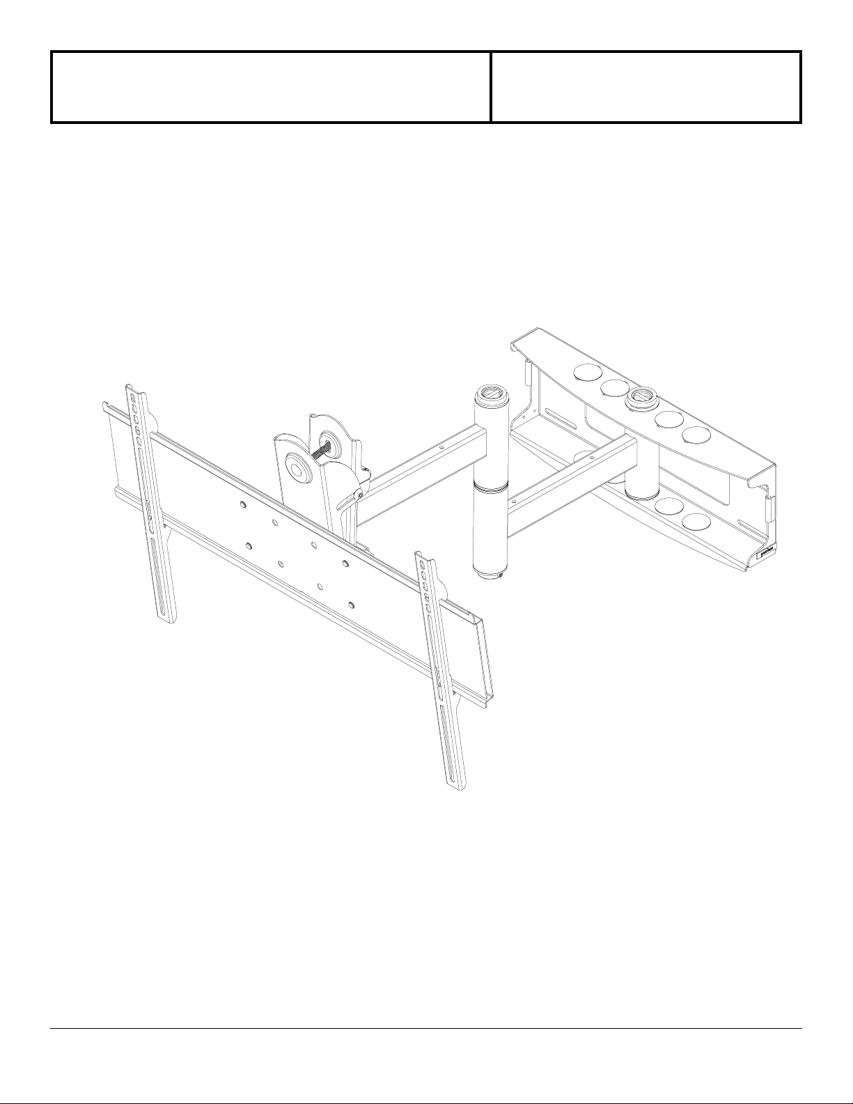
Installation and Assembly - Universal Articulating
Swivel Arm for 32" - 50" Plasma Screens
Models: PLA 50-UNL, PLA 50-UNL-S,
PLA 50-UNLP, PLA 50-UNLP-S,
RTPLA50-S
Maximum Load Capacity
::
: 150 lb (68 kg)
::
3215 W. North Ave. • Melrose Park, IL 60160 • (800) 729-0307 or (708) 865-8870 • Fax: (708) 865-2941 • www.peerlessmounts.com
ISSUED: 06-05-06 SHEET #: 202-9140-3 08-17-06
Page 2
Read instruction sheet before you start inst allation and assembly.
WARNING
• Do not begin to install your Peerless product until you have read and understood the instructions and warnings
contained in this Installation Sheet. If you have any questions regarding any of the instructions or warnings, please
call Peerless customer care at 1-800-729-0307.
• This product should only be installed by a qualified professional.
• Make sure that the supporting surface will safely support the combined load of the equipment and all attached hardware and components.
• Never exceed the Maximum Load Capacity of 150 lb (68 kg).
• Never mount this product to metal studs.
• If mounting to wood wall studs, make sure that mounting screws are anchored into the center of the studs. Use of an
"edge to edge" stud finder is highly recommended.
• Always use an assistant or mechanical lifting equipment to safely lift and position equipment.
• Tighten screws and nuts firmly , but do not overtighten. Overtightening can damage the items, greatly reducing their
holding power.
IMPORT ANT! Certain types of walls require additional mounting hardware...
WALL CONSTRUCTION ADDITIONAL HARDW ARE REQUIRED
Wood Stud, Wood Beam none
Solid Concrete Contact Customer Care for accessory kit
Other or unsure? Contact Customer Care
IMPORT ANT! T urn to the appropriate p age for your wall inst allation.
Installations:
To Wood Stud Walls ...................................................................................................... page 6
To Concrete Walls .......................................................................................................... page 7
Accessories
• concrete anchor 4-pack (ACC 210)
Tools Needed for Assembly
• stud finder ("edge to edge" stud finder is recommended)
• drill
• 3/16" drill bit for wood studs
• 5/16" drill bit for concrete
• 7/16" socket wrench with extension (recommended) for wood screws
• 10 mm socket wrench for concrete anchors
• level
• phillips screwdriver
2 of 13
ISSUED: 06-05-06 SHEET #: 202-9140-3 08-17-06
Page 3
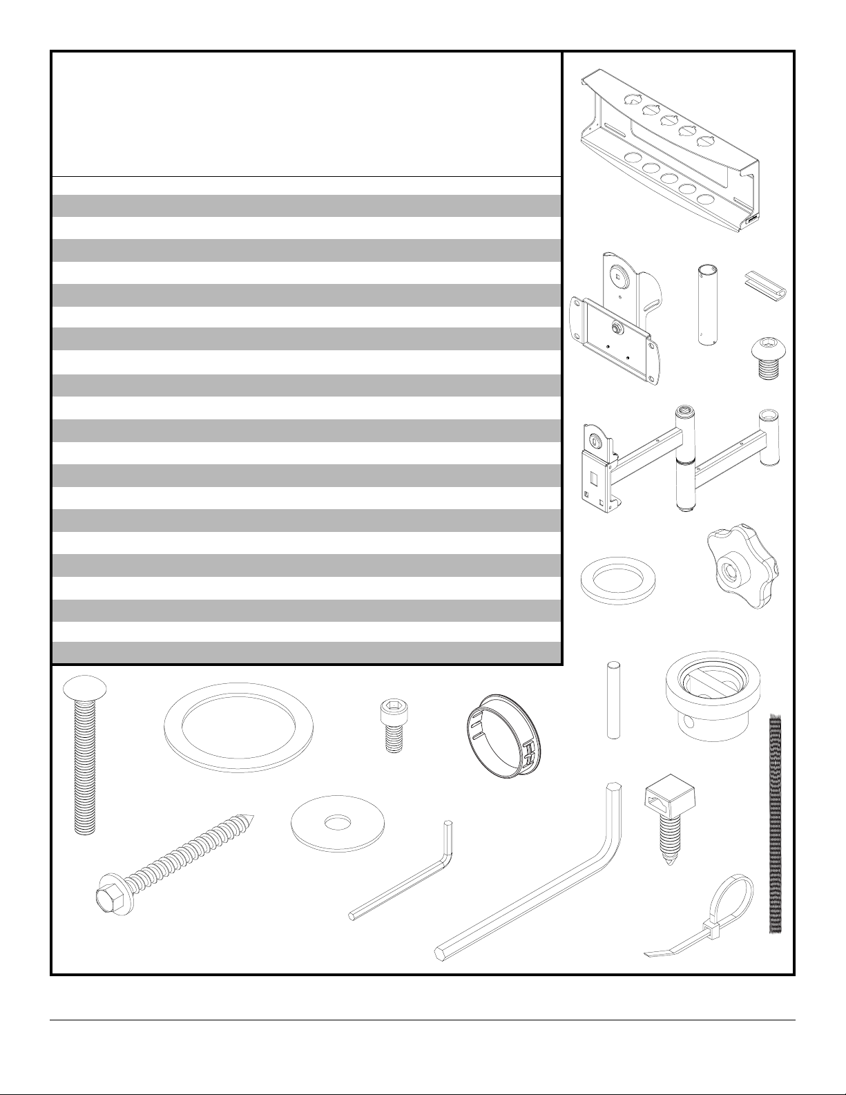
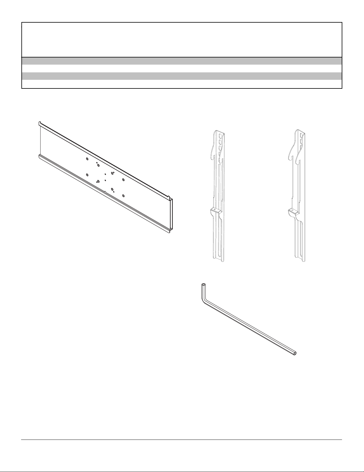
Wall Mount Parts List
DESCRIPTION QTY. PART # PART #
A wall plate 1 201-1095 201-4095
B tilt-roll assembly 1 201-1093 201-4093
C arm assembly 1 201-1094 201-4094
D wall support arm axle 1 201-1041 201-1041
E vinyl trim 3 600-1012 600-1012
Before you start make sure all parts
listed are included with your product.
MODEL MODEL
PLA 50-UNL RTPLA50-S
PLA 50-UNLP PLA 50-UNL-S
PLA 50-UNLP-S
A
F M10 x 1.5 x 15 mm screw bolt 8 520-9262 520-9262
G .505 x .75 x .062" nylon washer 1 540-1074 540-1074
H tilt adjustment knob 1 560-0108 560-0108
I carriage bolt 3/8"-16 x 3.25" 1 520-1315 520-1315
J 1.525 x 2 x .062" delrin washer 2 540-1070 540-1070
K #8-32 x .375" socket head cap screw 1 520-1210 520-1210
L plastic finishing cap 8 590-1123 590-1123
M holding pin 1 580-1166 580-1166
N retainer plug 1 590-1007 590-1007
O 5/16 x 3" wood screw 6 520-1243 520-1243
P .250 x 1 x .068" washer 6 540-1063 540-1063
Q 9/64" allen wrench 1 560-9728 560-9728
R cable management clips 4 590-1166 590-1166
S cable tie 4 590-1168 590-1168
T 36" polyester mesh sleeve 1 600-1015 600-1015
U 6 mm allen wrench 1 560-9716 560-9716
B
G
C
D
E
F
H
J
I
O
Some parts may appear slightly different than illustrated.
P
K
Q
3 of 13
L
M
N
R
U
S T
ISSUED: 06-05-06 SHEET #: 202-9140-3 08-17-06
Page 4
Before you begin, make sure all parts shown are included with your product.
Adapter Bracket P art s L ist
De scri p ti o n Qty Part # Part # Part # Par t #
adapter brack et 1 201-1110 201-4110 201-1110 201-4110
AA
shal low adapter brac ket 2 200-0756 200-0757 200-0754 200-0755
BB
deep adapter brack et 2 200-0752 200-0753 200-0750 200-0751
CC
allen wrench 1 560-9646 560-9646 560-0072 560-0072
DD
PL A 5 0-UN L PL A 5 0-UNL - S PLA 50 -UNL P PL A 5 0-UNLP- S
RTPLA50-S
AA
BB
CC
4 of 13
DD
ISSUED: 06-05-06 SHEET #: 202-9140-3 08-17-06
Page 5

Security Adapter Bracket Fasteners
M4 x 12 mm (6)
510-1079
M4 x 25 mm (4)
510-1082
I.D. 5.6 mm (4)
540-1057
M5 x 12 mm (4)
520-1064
M6 x 30 mm (4)
520-1067
I.D. 8.7 mm (4)
540-1059
Phillips Adapter Bracket Fasteners
M6 x 12 mm (4)
520-1050
M6 x 25 mm (4)
520-121 1
M8 x 15 mm (6)
520-1068
M8 x 25 mm (4)
520-1 101
M6 x 20 mm (4)
520-9554
M8 x 40 mm (4)
520-1 152
M5 x 25 mm (4)
520-1 122
multi-washer (6)
580-1036
M4 x 12 mm (6)
504-9013
M4 x 25 mm (4)
504-1015
I.D. 5.6 mm (4)
540-1057
M5 x 12 mm (4)
520-1027
M6 x 30 mm (4)
510-9109
M6 x 12 mm (4)
520-1 128
M6 x 25 mm (4)
520-1208
I.D. 8.7 mm (4)
540-1059
M8 x 16 mm (6)
M8 x 25 mm (4)
5 of 13
520-9257
520-1031
M6 x 20 mm (4)
520-9402
M8 x 40 mm (4)
520-1 136
ISSUED: 06-05-06 SHEET #: 202-9140-3 08-17-06
M5 x 25 mm (4)
520-9543
multi-washer (6)
580-1036
Page 6

Installation to Wood Stud Wall
WARNING
• Installer must verify that the supporting surface will safely support the combined load of the equipment and all attached
hardware and components.
• Tighten wood screws so that wall plate is firmly attached, but do not overtighten. Overtightening can damage the
screws, greatly reducing their holding power.
• Never tighten in excess of 80 in. • lb (9 N.M.).
• Never mount this product to metal studs.
• Make sure that mounting screws are anchored into the center of the stud. The use of an "edge to edge" stud finder is
highly recommended.
• Hardware provided is for attachment of mount through standard thickness drywall or plaster into wood studs. Installers
are responsible to provide hardware for other types of mounting situations.
• Never exceed the Maximum Load Capacity of 150 lb (68 kg).
Wall plate (A) can be mounted to two studs that are 16" apart. Use a stud finder to locate the edges of the studs.
1
Use of an edge-to-edge stud finder is highly recommended. Based on their edges, draw a vertical line down each
stud’s center . Place wall plate on wall as a template. The top mounting slots should be located 3.9" below the
desired screen center. Level plate, and mark the center of the four mounting holes. Make sure that the mounting
holes are on the stud centerlines. Drill six 3/16" (5 mm) dia. holes 3" (76 mm) deep. Make sure that the wall plate is
level, secure it using six 5/16 x 3" wood screws (O) and washers (P).
Skip to step 2 on page 8.
O
P
6 of 13
A
ISSUED: 06-05-06 SHEET #: 202-9140-3 08-17-06
Page 7

Installation to Concrete Wall
WARNING
• Concrete must be 2000 psi density minimum. Lighter density concrete may not hold concrete anchor .
• Make sure that the supporting surface will safely support the combined load of the equipment and all attached hardware and components.
• Never exceed the Maximum Load Capacity of 150 lb (68 kg).
Note: Fasteners for concrete walls are not included,
order TWO #ACC 210 accessory kits for installation
on concrete walls.
Make sure that wall plate (A) is level, use it as a tem-
1
plate to mark six mounting holes. The top mounting slots
should be located 3.9" below the desired screen center.
Drill six 5/16" (8 mm) dia. holes to a minimum depth of
1.75" (45 mm). Attach wall plate (A) using concrete
expansion anchors and washers (P) as shown in 1-1
through 1-4.
Align hole in wall plate (A) with hole in wall. Gently
1-1
hammer in concrete anchor as shown.
Use a 10 mm wrench (not provided) to tighten concrete
1-2
anchor to 80 in • lb (9 N.M.) maximum torque as shown.
P
A
FOR PRODUCT SAFETY USE ONL Y RA WL™
1-3
#5005 OR HIL TI™ HL814 CONCRETE ANCHORS.
Order TWO #ACC 210 accessory kits, each contains
four .312 x 1.625 (8 mm x 41 mm) concrete expansion anchors.
Concrete expansion anchors are not intended for
1-4
attachment to concrete covered with a layer of plaster ,
drywall, or other finishing material.
WARNING
• Tighten concrete anchor bolt firmly , but do not overtighten. Overtightening can damage the bolt, greatly
reducing its holding power.
• Never tighten in excess of 80 in • lb (9 N.M.).
WARNING
• Always attach concrete expansion anchors directly to
load-bearing concrete.
• Never attach concrete expansion anchors to concrete
covered with plaster, drywall, or other finishing material.
1-1
1-2
CUT AW A Y VIEW
P
A
1-3
1-4
7 of 13
ISSUED: 06-05-06 SHEET #: 202-9140-3 08-17-06
Page 8

WARNING
• If you are uncertain that product is properly installed, call customer care.
Note: There are five mounting positions. The
2
center position is shown (right). Slide washer (J)
over wall support arm axle (D). Next, insert plastic
cap (N) into axle. Then, insert holding pin (M) into
axle. See detail 1.
Place arm assembly (C) with washer (J) into wall
2-1
plate (A). Insert axle assembly shown in detail 1
through wall plate (A), arm assembly (C), and
washer (J). Lock axle in place by aligning holding
pin (M) with notches shown in detail 2.
N
J
D
M
DETAIL 1
A
Insert socket cap screw (K) into hole at bottom of
2-2
wall support arm axle (D) as shown in detail 3.
Tighten screw using 9/64" allen wrench (Q).
Note: Fit of axle (D) into wall plate (A) and arm
assembly (C) will be tight. Gently tap into place
with a hammer if necessary .
C
J
K
D
DETAIL 3
Snap four cable management clips (R) into top or bottom of arm assembly (C) as shown. Cable ties (S) are used with
3
clips for cord management.
Slide one mesh sleeve (T) over each cable. Use cable ties (S) to tighten mesh sleeves to cables.
3-1
NOTCH
DETAIL 2
S
C
R
8 of 13
T
ISSUED: 06-05-06 SHEET #: 202-9140-3 08-17-06
Page 9

Attach two pieces of vinyl trim (E) to wall plate (A). Next, attach one piece of vinyl trim to bottom of swivel box on arm
4
assembly (C).
Insert one finishing cap (L) into each unused hole of wall plate (A).
4-1
L
C
SWIVEL BOX
E
Insert and tape carriage bolt (I) into top hole of tilt-roll assembly (B). Att ach tilt-roll assembly to adapter bracket
5
(AA) with four M10 socket screws (F). Tighten screws using 6 mm allen wrench (U).
CAUTION
A
• Do not overtighten screws! Overtightening may hinder
roll option.
B
F
9 of 13
AA
I
ISSUED: 06-05-06 SHEET #: 202-9140-3 08-17-06
Page 10

WARNING
• Use an assistant or mechanical lifting equipment to safely lift and position the plasma TV.
Insert two M10 screws (F) into swivel box on arm assembly (C) as shown. Leave approx. 1/4" of exposed thread.
6
SWIVEL BOX
C
.25"
F
Hook tilt-roll assembly (B) onto M10 screws (F).
6-1
Insert carriage bolt (I) into slot of swivel box as
shown in figure 6.1. Install nylon washer (G) and tilt
adjustment knob (H).
Install remaining two M10 screws (F) as shown in
6-2
figure 6.2. HAND TIGHTEN all four M10 screws to
allow for tilt adjustment. Remove tape from carriage
bolt (I). For tilt adjustment, push back on the top of
plasma to relieve pressure on knob. Adjust tilt to
desired position and tighten tilt adjustment knob (H),
then securely tighten all four M10 screws (F) using 6
mm allen wrench (U).
H
SWIVEL BOX
G
I
CAUTION
• After tilt is adjusted, all fasteners must be tightened.
Failure to do so will result in damage to the mount.
H
I
F
F
B
Adapter bracket not shown for clarity . Adapter bracket not shown for clarity .
fig 6.1 fig 6.2
10 of 13
ISSUED: 06-05-06 SHEET #: 202-9140-3 08-17-06
Page 11

Installing Adapter Brackets
Refer to Screen Compatibility Chart to determine the proper fasteners to use.
To prevent scratching the screen, set a cloth on a flat, level surface that will support the weight of the screen. Place
7
screen face side down. If screen has knobs on the back, remove them to allow the adapter brackets to be attached.
Place adapter brackets (BB or CC) on back of screen, align to holes, and center on back of screen as shown in figure
7.1. Att ach the adapter brackets to the back of the screen using the appropriate combination of screws, multi-washers, and spacers as shown in figure 7.3.
Note: Top and bottom holes must always be used.
Verify that all holes are properly aligned, and then tighten screws using a phillip s screwdriver.
Note: If using security screws, tighten using security allen wrench (DD).
WARNING
• Tighten screws so adapter brackets are firmly
attached. Do not tighten with excessive force.
Overtightening can cause stress damage to screws,
greatly reducing their holding power and possibly
causing screw heads to become detached. Tighten to
40 in. • lb (4.5 N.M.) maximum torque.
Notes:
• The number of fasteners used will vary ,
depending upon the type of screen.
• Multi-washers and spacers may not be
used, depending upon the type of screen.
BB
or
CC
fig 7.1
CENTER BRACKETS
VERTICALLY ON BACK OF
SCREEN
Note: "X" dimensions should be equal.
X
X
• Use the corresponding hole in the multiwasher that matches your screw size as
shown in figure 7.2.
WARNING
• If screws don't get three complete turns in the screen
inserts or if screws bottom out and bracket is still not
tightly secured, damage may occur to screen or
product may fail.
MULTI-WASHER
MEDIUM HOLE FOR M5 SCREWS
SMALL HOLE FOR M4 SCREWS
LARGE HOLE FOR M6 SCREWS
fig. 7.2
BB or CC
SCREWS
MULTIWASHER
SPACERS
fig 7.3
11 of 13
ISSUED: 06-05-06 SHEET #: 202-9140-3 08-17-06
Page 12

Mounting and Removing Flat Panel Screen
Refer to mount instruction sheet for attachment of adapter bracket to mount.
Hook adapter brackets (BB or CC) onto adapter bracket (AA), then slowly swing screen in as shown. Turn screws
8
clockwise at least six times to prevent screen from being removed as shown in detail 4. Tighten using allen wrench (DD).
Screen can be adjusted horizontally if desired.
Note: To lock the screen down, tighten screws to adapter bracket as shown in detail 4.
T o remove screen from mount, loosen screws, swing screen away from mount, and lift screen off of mount.
WARNING
• Always use an assistant or mechanical lifting equipment to safely lift and position the plasma television.
AA
SCREWS
BB
or
CC
BB or CC
AA
DETAIL 4
12 of 13
ISSUED: 06-05-06 SHEET #: 202-9140-3 08-17-06
Page 13

Depending on the specific size & weight of the plasma, articulating swing arm may be angled at different positions,
9
causing plasma to appear to lean sideways at different articulating positions. Tilt-roll assembly (B) allows plasma to
be manually adjusted, so plasma can be horizontal at all positions. To adjust, gently rotate plasma by hand to desired
position.
ARTICULA TING ARM
PLASMA
If it is too difficult to adjust roll of plasma, loosen screws shown in figure 9.1 using a phillips screwdriver .
9-1
IMPORTANT! Do not loosen or tighten screws more than 1/8 turn.
ROLL
ADJUSTMENT
SCREWS
fig 9.1
13 of 13
All other brand and product names are trademarks or registered trademarks of their respective owners.
ISSUED: 06-05-06 SHEET #: 202-9140-3 08-17-06
©2006 Peerless Industries, Inc. All rights reserved.
Peerless is a registered trademark of Peerless Industries, Inc.
 Loading...