

Page 1
Installation and Assembly:
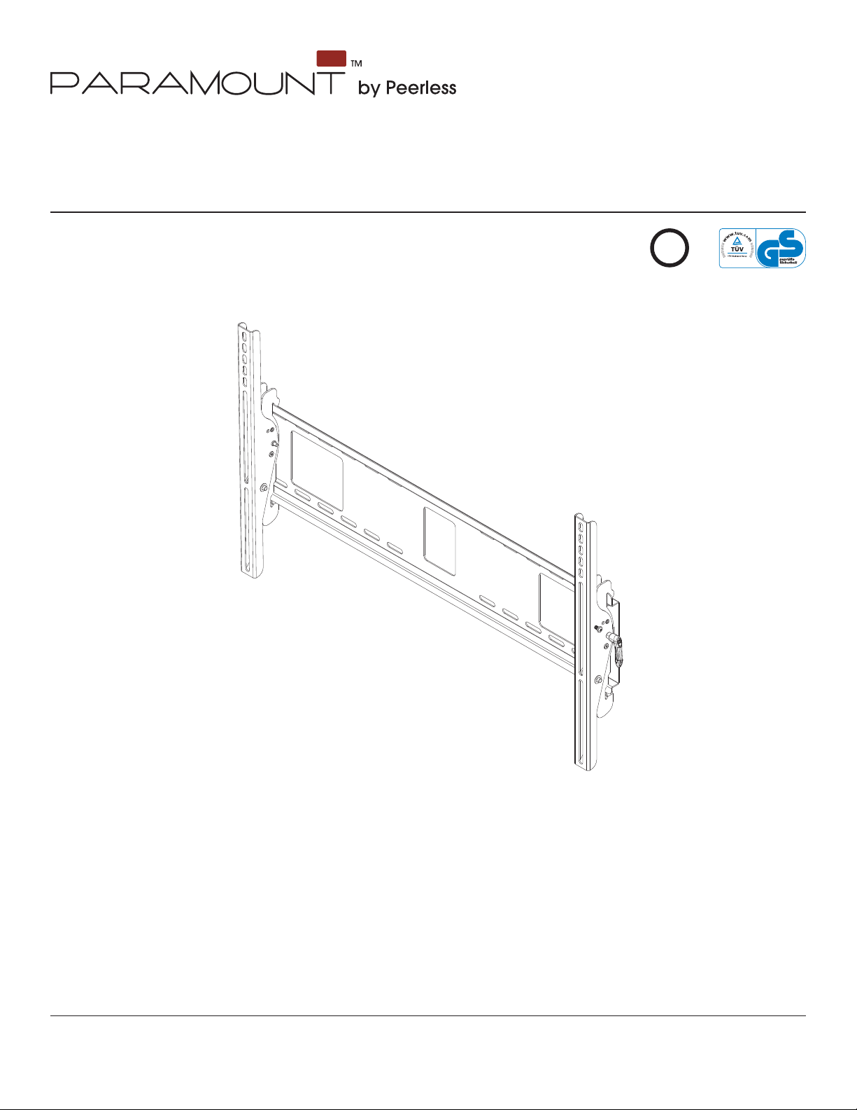
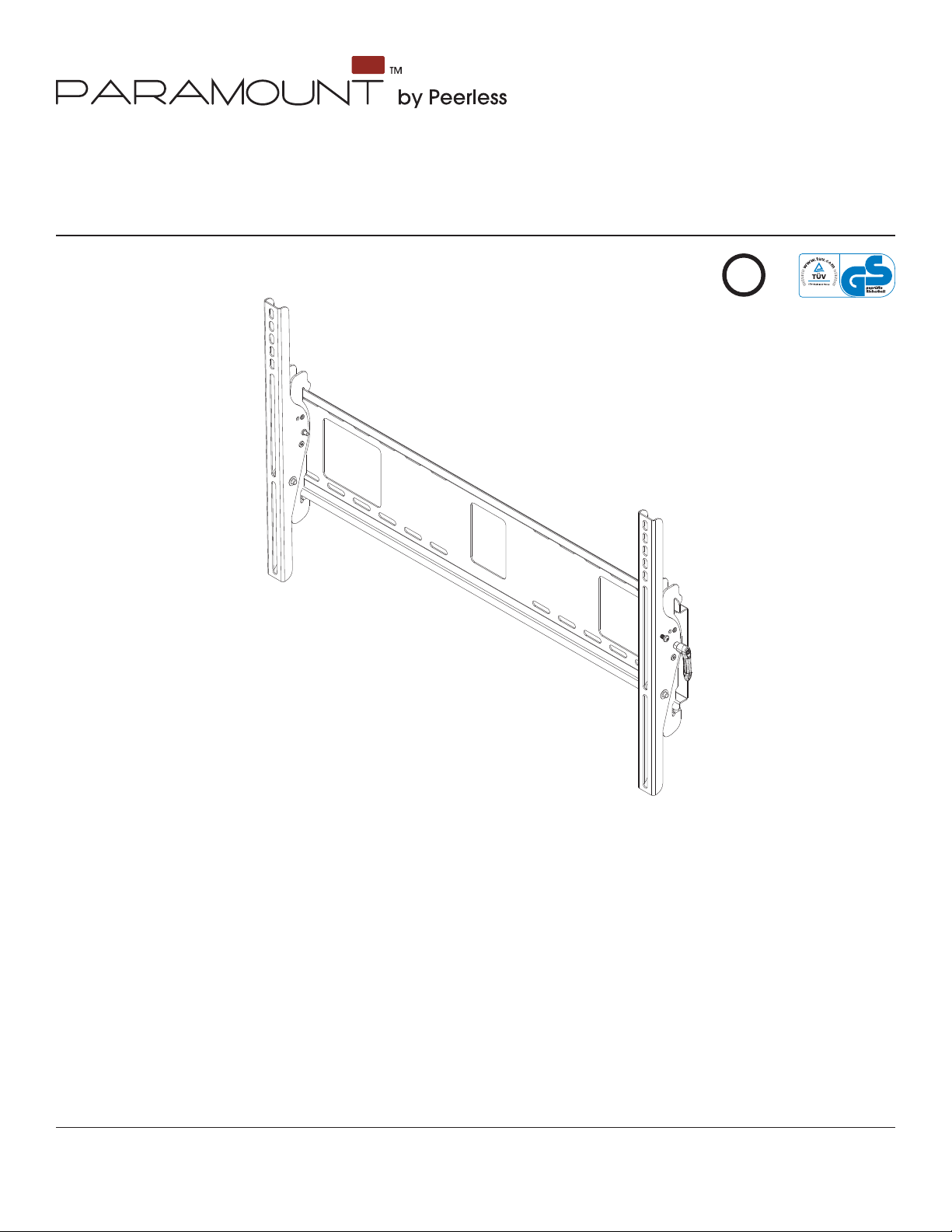
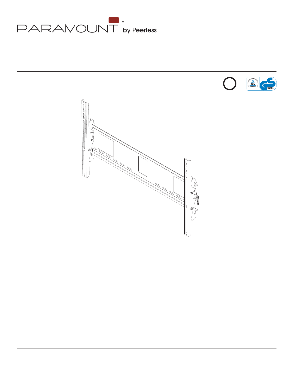
Universal Tilt Wall Mounts
for 37" - 60" (94 - 152 cm) Flat Panel Screens
Model: PT660, PWS421/BK
U
©
L
I
USC
D
2
:
6
0
7
0
8
0
1
0
0
Max Load Capacity: 200 lb (90.7kg)
Features:
• Universal mount fi ts screens with mounting hole patterns up to 29.06" W x 17.67" H (738 mm W x 449 mm H)
• Screen held only 2.5" (64 mm) from wall for a discreet installation
• Open wall plate design allows for greater wall and an array of cable management options
• Universal tilt brackets easily hook onto the wall plate for fast installation
• Adjustable up to 15° of forward tilt and up to -5° backward tilt for optimal viewing angle
• One-touch tilt for effortless adjustment
• Pre-tensioned universal tilt bracket allows for tilt angle adjustment in one easy motion.
• Easy locking handle locks the screen position into place without the use of tools
• Optional IncreLok feature offers fi xed tilts at -5°, 0°, 5°, 10°, 15° increments
• Includes Sorted-For-You™ fastener packs for installation to wood studs, concrete and cinder block
• Optional horizontal adjustment of up to 8" (203 mm) (depending on screen model) for perfect screen placement
ISSUED: 02-05-09 SHEET #: 202-9272-4 04-12-10
Page 2

NOTE: Read entire instruction sheet before you start installation and assembly.
WARNING
• Do not begin to install your Peerless product until you have read and understood the instructions and warnings
contained in this Installation Sheet. If you have any questions regarding any of the instructions or warnings, for US
customers please call Peerless customer care at 1-800-865-2112, for all international customers, please contact
your local distributor.
• This product should only be installed by someone of good mechanical aptitude, has experience with basic building
construction, and fully understands these instructions.
• Make sure that the supporting surface will safely support the combined load of the equipment and all attached
hardware and components.
• Never exceed the Maximum Load Capacity. See page one.
• If mounting to wood wall studs, make sure that mounting screws are anchored into the center of the studs. Use of
an "edge to edge" stud fi nder is highly recommended.
• Always use an assistant or mechanical lifting equipment to safely lift and position equipment.
• Tighten screws fi rmly, but do not overtighten. Overtightening can damage the items, greatly reducing their holding
power.
• This product is intended for indoor use only. Use of this product outdoors could lead to product failure and personal
injury.
• This product was designed to be installed on the following wall construction only;
WALL CONSTRUCTION HARDWARE REQUIRED
• Wood Stud Included
• Wood Beam Included
• Solid Concrete Included
• Cinder Block Included
• Metal Stud Do not attach except with Peerless Metal Stud Accessory Kit - ACC415;
(not evaluated by UL)
• Brick Contact Qualifi ed Professional (not evaluated by UL)
• Other or unsure? Contact Qualifi ed Professional
Tools Needed for Assembly
• stud fi nder ("edge to edge" stud fi nder is recommended)
• phillips screwdriver
• drill
• 5/16" (8 mm) bit for concrete and cinder block wall
• 5/32" (4 mm) bit for wood stud wall
• level
Table of Contents
Parts List.................................................................................................................................................................................3
Installation to Double Wood Stud Wall ...................................................................................................................................4
Installation to Solid Concrete or Cinder Block ........................................................................................................................5
Installing Tilt Brackets .............................................................................................................................................................6
Mounting and Removing Flat Panel Screen ...........................................................................................................................8
2 of 34
ISSUED: 02-05-09 SHEET #: 202-9272-4 04-12-10
Page 3
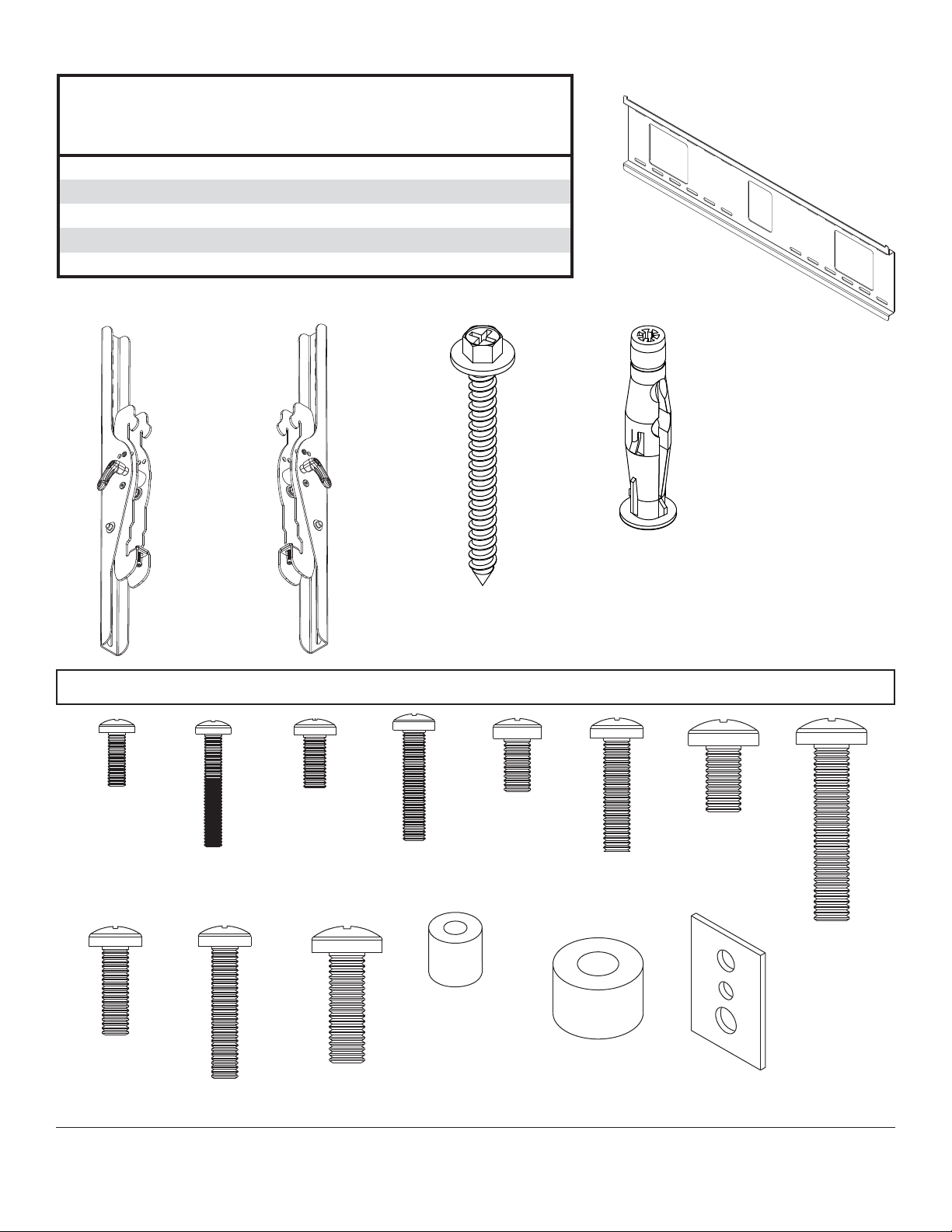
Before you begin, make sure all parts shown are included with your product.
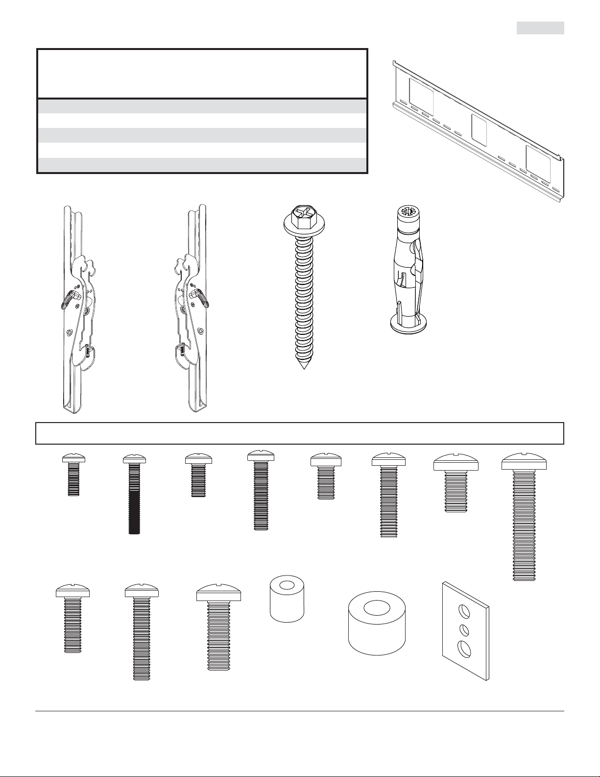
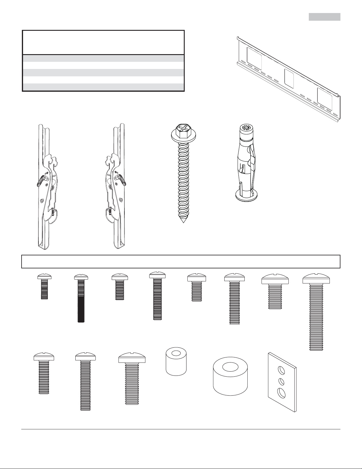
Parts List
Description
AA wall plate 1 201-P1018
BB left tilt bracket 1 201-P1471
CC right tilt bracket 1
DD #14 x 2.5" wood screw 4 5S1-015-C03
EE concrete anchor 4 590-0320
Parts may appear slightly different than illustrated.
BB CC
Qty Part #
201-P1469
DD
AA
EE
M4 x 12 mm (6)
504-9013
M6 x 20 mm (4)
520-9402
M4 x 25 mm (4)
504-1015
M6 x 30 mm (4)
510-9109
Tilt Bracket Fasteners
M5 x 12 mm (4)
520-1027
M8 x 25 mm (4)
520-1031
M6 x 12 mm (4)
M5 x 25 mm (4)
520-9543
I.D. .22" (5.6 mm) (4)
540-1057
3 of 34
520-1128
M6 x 25 mm (4)
520-1208
I.D. .34" (8.7 mm) (4)
540-1059
M8 x 16 mm (6)
520-9257
M8 x 40 mm (4)
520-1136
multi-washer (6)
580-1036
ISSUED: 02-05-09 SHEET #: 202-9272-4 04-12-10
Page 4
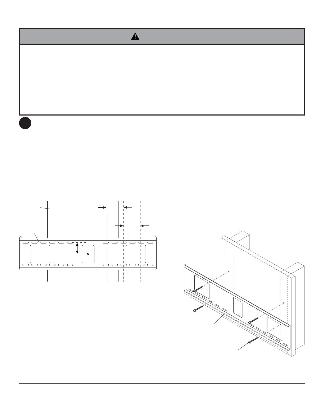
Installation to Double Wood Stud Wall
WARNING
• Installer must verify that the supporting surface will safely support the combined load of the equipment and all
attached hardware and components.
• Tighten wood screws so that wall plate is fi rmly attached, but do not overtighten. Overtightening can damage the
screws, greatly reducing their holding power.
• Never tighten in excess of 80 in. • lb (9 N.M.).
• Make sure that mounting screws are anchored into the center of the stud. The use of an "edge to edge" stud fi nder
is highly recommended.
• Hardware provided is for attachment of mount through standard thickness drywall or plaster into wood studs. Installers are responsible to provide hardware for other types of mounting situations (not UL approved).
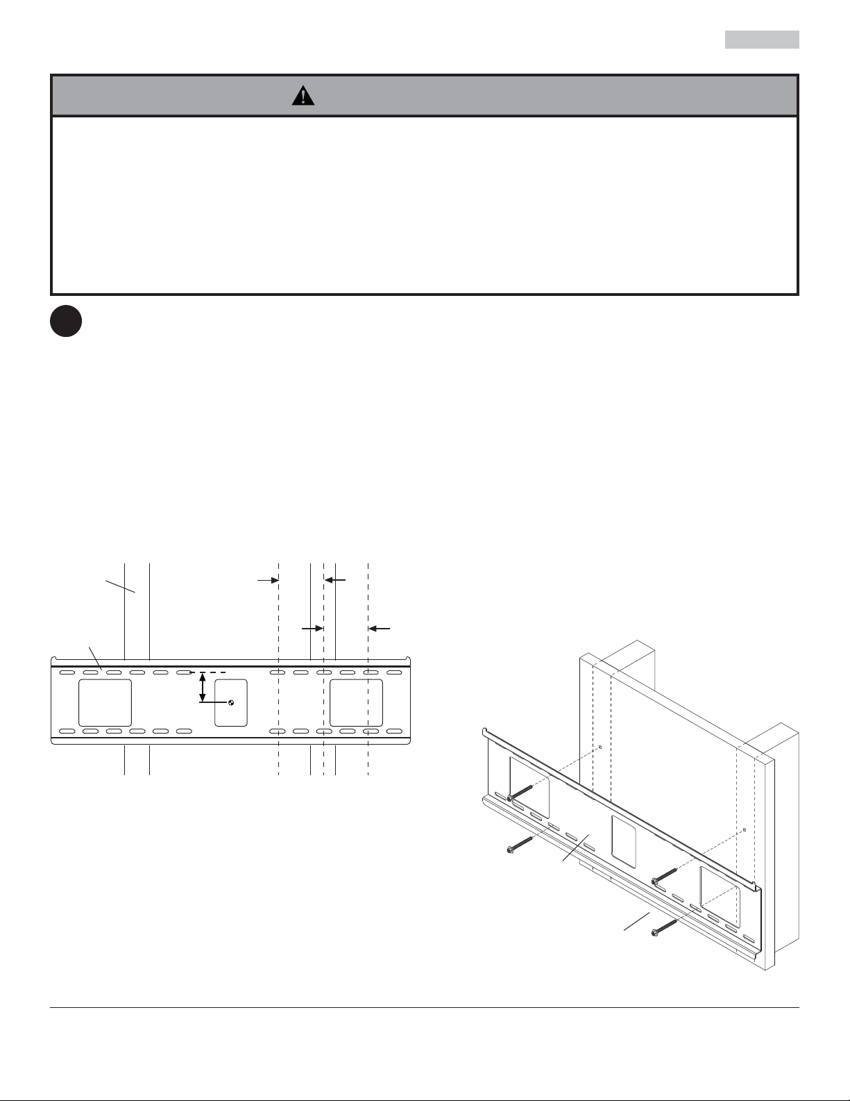
Use a stud fi nder to locate the edges of the studs. Use of an edge-to-edge stud fi nder is highly recommended.
1
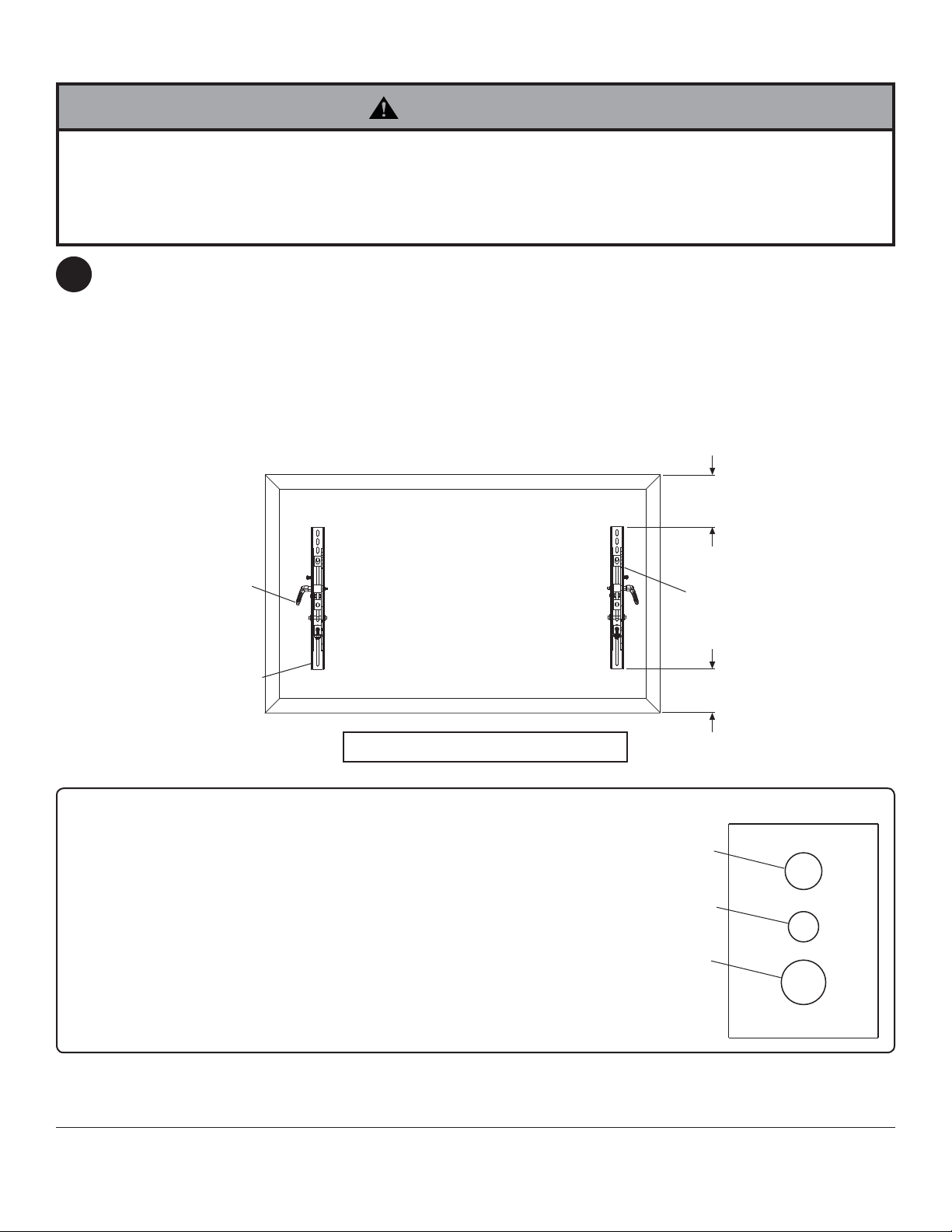
Based on their edges, draw a vertical line down each stud’s center. Place wall plate on wall as a template. The top
mounting slots should be 2.5" (64 mm) above the desired screen center as shown in fi gure 1.1. Level plate, and
mark the center of the four mounting holes. Make sure that the mounting holes are on the stud centerlines. Drill four
5/32" (4 mm) dia. holes 2.5" (64 mm) deep. Make sure that the wall plate is level, secure it using four #14 x 2.5"
wood screws (DD) as shown in fi gure 1.2.
NOTE: Wall plate may be mounted up to 4" (102 mm) off center as shown in fi gure 1.1.
Skip to step 2.
STUD
AA
2.5"
(64 mm)
CS = center of screen
4"
(102 mm)
4"
(102 mm)
CS
fi g. 1.1
AA
DD
4 of 34
fi g. 1.2
ISSUED: 02-05-09 SHEET #: 202-9272-4 04-12-10
Page 5
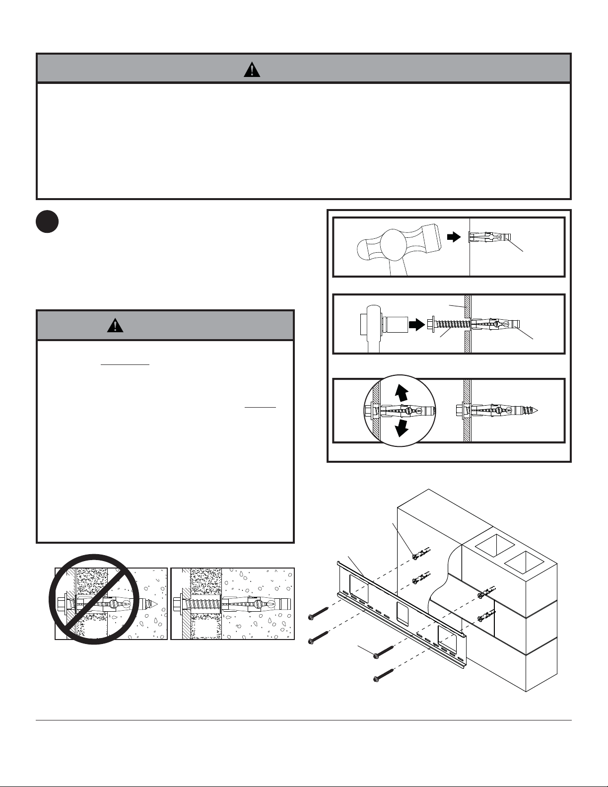
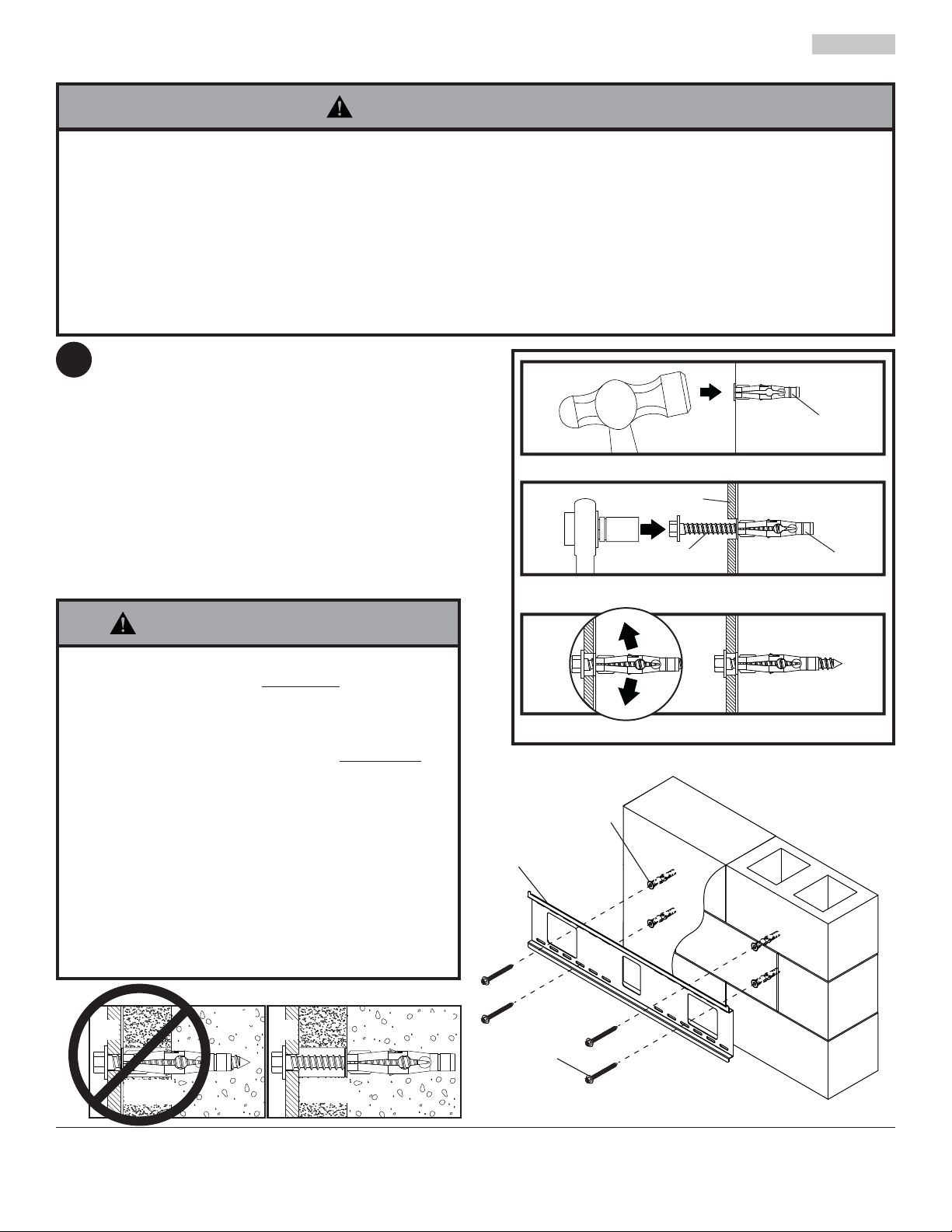
Installation to Solid Concrete or Cinder Block
WARNING
• When installing Peerless wall mounts on cinder block, verify that you have a minimum of 1-3/8" (35 mm) of actual
concrete thickness in the hole to be used for the concrete anchors. Do not drill into mortar joints! Be sure to mount
in a solid part of the block, generally 1" (25 mm) minimum from the side of the block. Cinder block must meet ASTM
C-90 specifi cations. It is suggested that a standard electric drill on slow setting is used to drill the hole instead of a
hammer drill to avoid breaking out the back of the hole when entering a void or cavity.
• Concrete must be 2000 psi density minimum. Lighter density concrete may not hold concrete anchor.
• Make sure that the wall will safely support four times the combined load of the equipment and all attached hardware
and components.
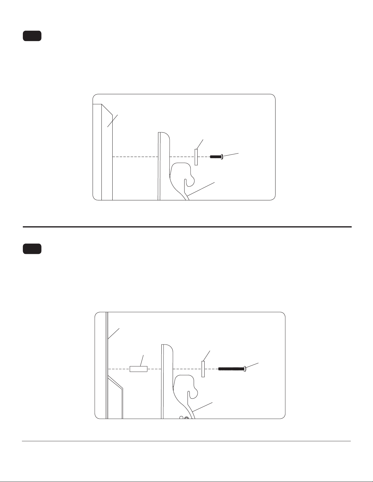
Make sure that wall plate (AA) is level, use it as a
1
template to mark four mounting holes. The top mounting
hole should be 2.5" (64 mm) above the desired screen
center as shown in fi gure 1.1 on page 4. Drill four 5/16"
(8 mm) dia. holes to a minimum depth of 2.5" (64 mm).
Insert anchors (EE) in holes fl ush with wall as shown
(right). Place wall plate over anchors and secure with
#14 x 2.5" screws (DD). Level, then tighten all fasteners.
1
Drill holes and insert anchors (EE).
2
AA
concrete
surface
EE
WARNING
• Tighten screws so that wall plate is fi rmly attached,
but do not overtighten. Overtightening can damage
screws, greatly reducing their holding power.
• Never tighten in excess of 80 in. • lb (9 N.M.).
• Always attach concrete expansion anchors directly
to load-bearing concrete.
• Never attach concrete expansion anchors to
concrete covered with plaster, drywall, or other
fi nishing material. If mounting to concrete surfaces
covered with a fi nishing surface is unavoidable (not
evaluated by UL), the fi nishing surface must be
counterbored as shown below. Be sure concrete
anchors do not pull away from concrete when
tightening screws. If plaster/drywall is thicker than
5/8" (16 mm), custom fasteners must be supplied
by installer (not evaluated by UL).
DD
Place plate (AA) over anchors (EE) and secure with screws (DD).
3
Tighten all fasteners.
solid concrete
EE
EE
cinder block
plate
CUTAWAY VIEW
wall
plaster/
dry wall
INCORRECT CORRECT
concrete
wall
plate
plaster/
dry wall
concrete
5 of 34
AA
DD
ISSUED: 02-05-09 SHEET #: 202-9272-4 04-12-10
Page 6
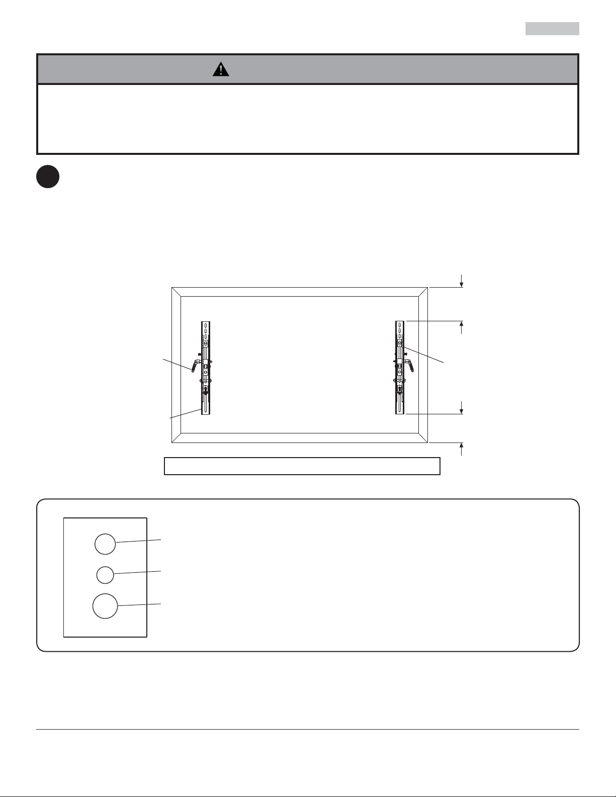
Attaching Tilt Brackets to Screen using Baffl ed Fastener Pack
WARNING
• Tighten screws so adapter brackets are fi rmly attached. Do not tighten with excessive force. Overtightening
can cause stress damage to screws, greatly reducing their holding power and possibly causing screw heads to
become detached. Tighten to 40 in. • lb (4.5 N.M.) maximum torque.
• If screws don't get three complete turns in the screen inserts or if screws bottom out and bracket is still not tightly
secured, damage may occur to screen or product may fail.
To prevent scratching the screen, set a cloth on a fl at, level surface that will support the weight of the screen. Place
2
screen face side down. Refer to screen manufacturers instructions or customer service, for removing any knobs,
base, cover or screw(s) on the back of the screen to prepare mounting. These need to be removed to allow the tilt
brackets to be attached. Select the small, medium, large or extra large screws from the baffl ed fastener pack then
attach tilt brackets to screen following fi gure 2.1 or 2.2.
NOTE: Top and bottom mounting holes on screen must be used for attaching brackets.
NOTE: Be sure to attach tilt brackets with handles facing outward as shown below. Verify that all holes are properly
aligned, and then tighten screws using a phillips screwdriver.
X
HANDLES FACE OUT
CENTER BRACKETS VERTICALLY ON BACK
BB
Note: "X" dimensions should be equal.
Notes:
• The number of fasteners used will vary, depending
upon the type of screen.
• Multi-washers and spacers may not be used,
depending upon the type of screen.
• Use the corresponding hole in the multi-washer
that matches your screw size as shown.
OF SCREEN
CC
X
MULTI-WASHER
MEDIUM HOLE FOR M5 SCREWS
SMALL HOLE FOR M4 SCREWS
LARGE HOLE FOR M6 SCREWS
NOTE: For fl at back screens proceed to step 2-1. For bump-out or recessed back screen skip to step 2-2.
6 of 34
ISSUED: 02-05-09 SHEET #: 202-9272-4 04-12-10
Page 7
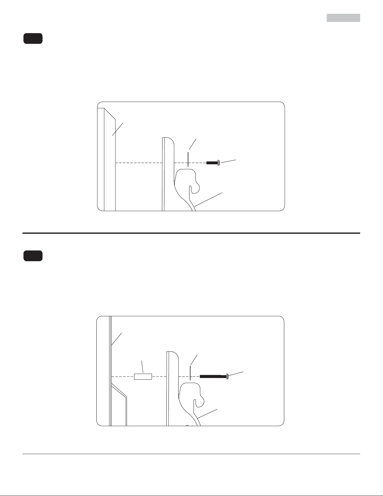
For Flat Back Screen
Begin with the shortest length screw, hand thread through multi-washer and tilt bracket into screen as shown
2-1
below. Screw must make at least three full turns into the mounting hole and fi t snug into place. Do not over tighten.
If screw cannot make three full turns into the screen, select a longer length screw from the baffl ed fastener pack.
Repeat for remaining mounting holes, level brackets and tighten screws.
NOTE: Spacers may not be used, depending upon the type of screen.
fi g. 2.1
SCREEN
MULTI-WASHER
SCREW
TILT BRACKET
(BB or CC)
For Bump-out or Recessed Back Screen
Begin with longer length screw, hand thread through multi-washer, tilt bracket and spacer in that order into screen
2-2
as shown below. Screw must make at least three full turns into the mounting hole and fi t snug into place. Do not
over tighten. If screw cannot make three full turns into the screen, select a longer length screw from the baffl ed
fastener pack. Repeat for remaining mounting holes, level brackets and tighten screws.
SCREEN
SPACER
fi g. 2.2
MULTI-WASHER
SCREW
TILT BRACKET
(BB or CC)
7 of 34
ISSUED: 02-05-09 SHEET #: 202-9272-4 04-12-10
Page 8
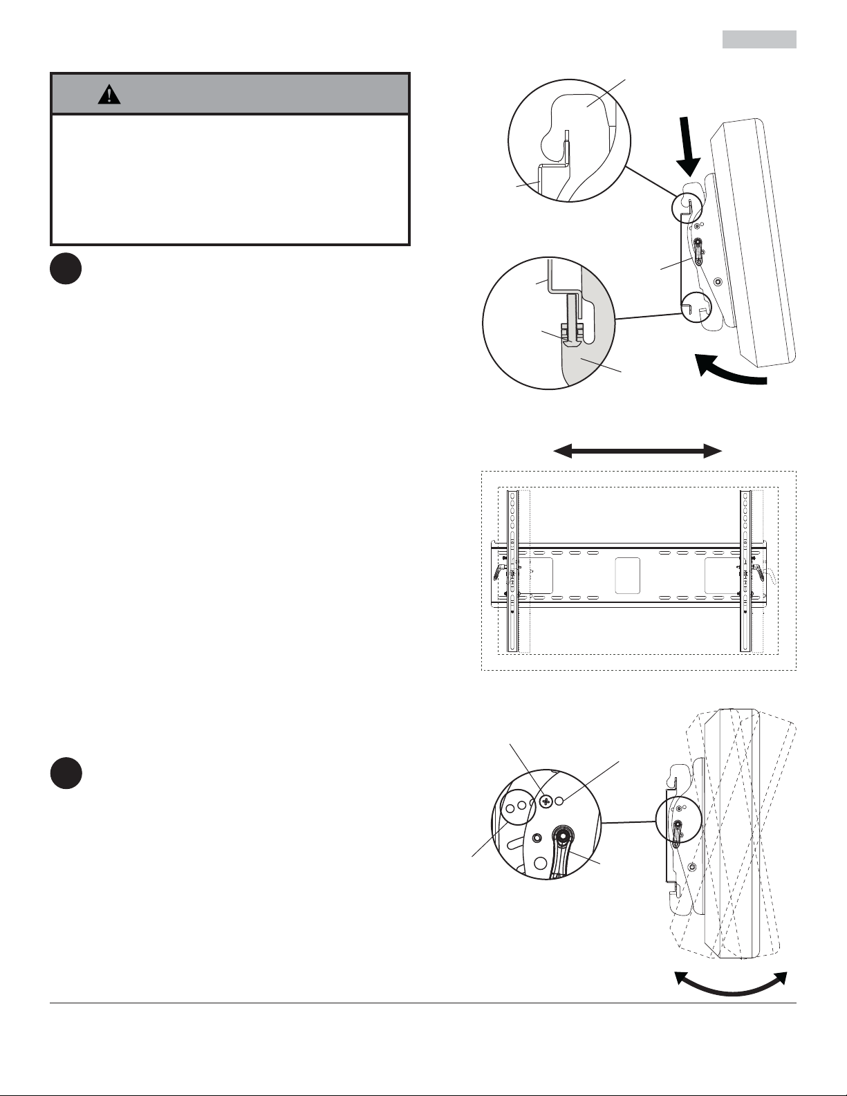
Mounting and Removing Flat Panel Screen
BB &
WARNING
• Always use an assistant or mechanical lifting equipment
to safely lift and position the fl at panel screen.
• Do not tighten screws with excessive force.
Overtightening can cause damage to mount. Tighten
screws to 40 in. • lb (4.5 N.M.) maximum torque.
• Be careful not to pinch fi ngers when pushing screen from
the bottom.
Tension Adjustment of Ratchet Handle: Adjust
tension in tilt brackets (BB & CC) by rotating
3
ratchet handle. NOTE: If obstruction prevents
ratchet handle from rotating, pull handle out while
turning will allow handle to reposition without
tightening. Release and turn handle to tighten or
loosen.
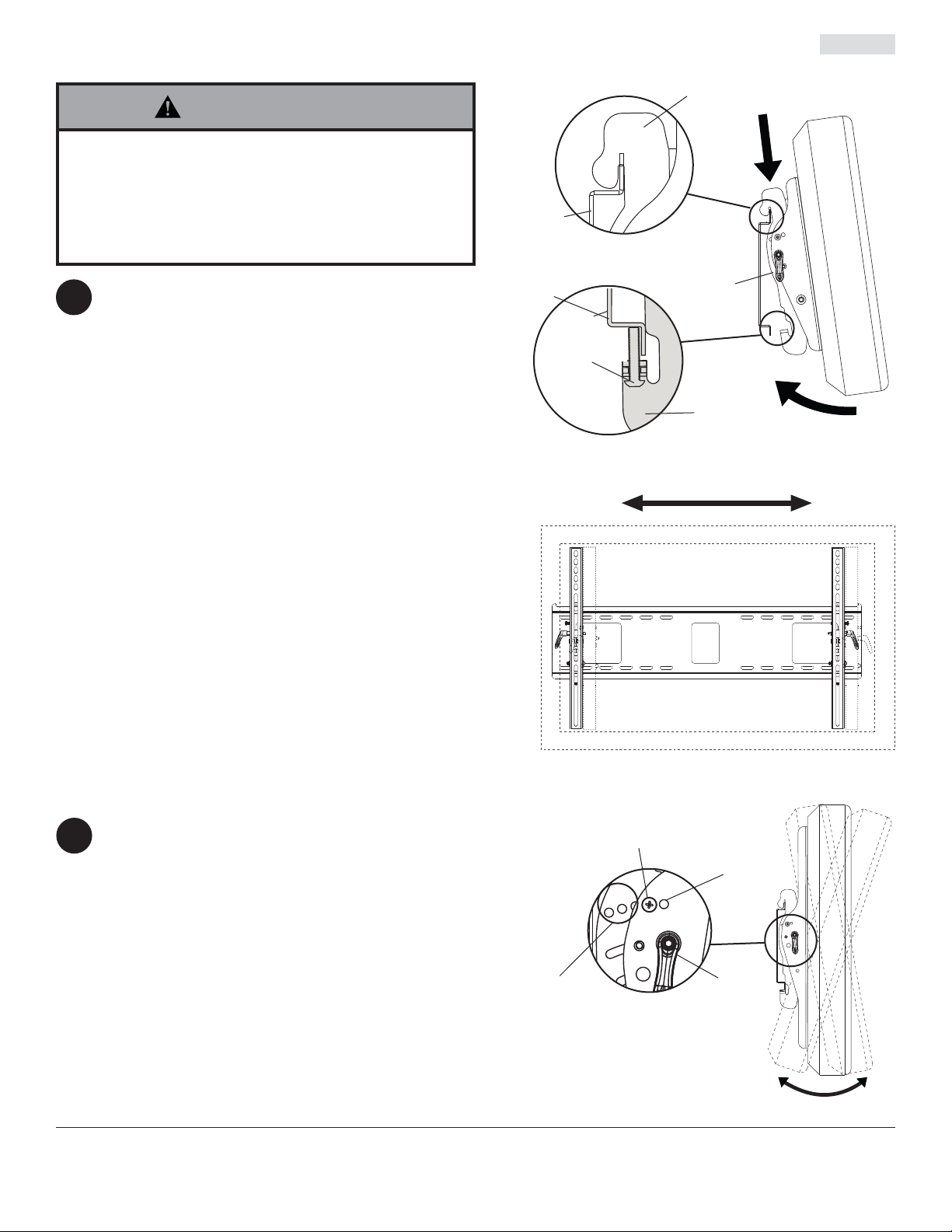
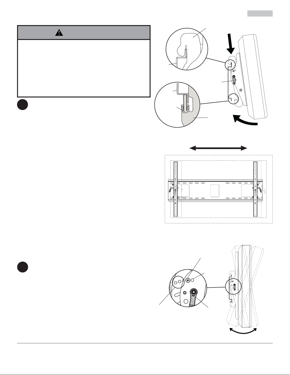
Mounting Screen: Ratchet handle must be in the
up or down position or interference will occur while
hooking tilt brackets to wall plate (AA). Slowly
hook tilt brackets (BB & CC) onto wall plate (AA)
and swing screen down as shown in fi g. 3.1. Tilt
bracket hooks must fully engage wall plate as
shown in detail 1. Using phillips screw driver, turn
safety screws on tilt brackets (BB & CC) clockwise
till screw tip securely contacts wall plate as shown
in cross section.
AA
DETAIL 1
RATCHET
HANDLE
AA
SAFETY
SCREW
CROSS SECTION
CC
BB &
CC
fi g 3.1
Screen Adjustment: Screen can be adjusted
horizontally by loosening safety screws on tilt
brackets (BB & CC) three full turns with phillips
screw driver. Adjust screen as shown in fi g. 3.2.
Tighten safety screws on tilt brackets till screw
tip securely contacts wall plate as shown in cross
section.
Removing Screen: To remove screen from mount,
loosen safety screws, swing screen away from
mount, and lift screen off of mount.
Adjusting the Tilt Angle of the Flat Panel
Screen
For preset tilt angles use Increlok™ and for
custom tilt angle use ratchet handle.
4
INCRELOK™: The screen can be locked into a
pre-set tilt position of -5°, 0°, 5°, 10° or 15°. Use
locator hole to fi nd tilt position hole and tilt screen
to align holes. Tighten IncreLok™ tilt locking
screws on both tilt brackets to lock tilt as shown in
detail 2.
Ratchet Handle: Loosen ratchet handle (refer
to step 3 for tension adjustment of handle). Push
or pull from top or bottom of screen to adjust tilt
as shown in fi g. 4.1. The tilt can be adjusted to a
maximum of 15° forward or 5° backward.
8 of 34
fi g 3.2
IncreLok™ TILT
LOCKING SCREW
LOCATOR
HOLE
TILT
POSITION
HOLES
DETAIL 2
RATCHET
HANDLE
fi g 4.1
ISSUED: 02-05-09 SHEET #: 202-9272-4 04-12-10
All other brand and product names are trademarks or registered trademarks of their respective owners.
© 2009, Peerless Industries, Inc. All rights reserved.
Peerless Industries, Inc.
3215 W. North Ave.
Melrose Park, IL 60160
www.peerlessmounts.com
Page 9

Instalación y montaje:
Soporte universal de pared Paramount™ con capacidad de inclinación para pantallas LCD y pantallas planas de plasma de
37" a 60" (94 - 152 cm)
Modelos: PT660, PWS421/BK
U
©
L
I
USC
D
2
:
6
0
7
0
8
0
1
0
0
Máxima capacidad de carga: 200 lb (90.7 kg)
Características:
• El soporte universal sostiene pantallas con confi guraciones de montaje de hasta 29.06" W x 17.67" H
(738 mm W x 449 mm H)
• Sostiene el televisor a sólo 2.5" (64 mm) de la pared para proporcionar una instalación discreta
• El diseño abierto de la placa de pared permite más acceso a la pared y proporciona una amplia variedad de opciones
para el manejo de cables
• Los soportes inclinables universales se enganchan con facilidad a la placa de pared para proporcionar una instalación
rápida
• Inclinación ajustable hacia delante de hasta 15° y hacia atrás de hasta -5° para ver el televisor desde un ángulo óptimo
• Inclinación de un solo toque para permitir el ajuste sin esfuerzo
• El soporte inclinable universal preapretado permite ajustar el ángulo de inclinación con un solo movimiento sencillo
• La palanca de fi jación fácil fi ja la posición de la pantalla con seguridad sin la necesidad de usar herramientas
• La función opcional IncreLok™ ofrece ángulos de inclinación predeterminados en incrementos de -5°, 0°, 5°, 10° y 15°
• Incluye el paquetes de sujetadores Sorted-For-You™ para instalaciones en montantes de madera, concreto y bloques
de hormigón de escorias
• Ajuste horizontal opcional de hasta 8" (203 mm) (dependiendo del modelo de la pantalla) para la colocación perfecta de
la pantalla
PUBLICADO: 02-05-09 HOJA #: 202-9272-4 04-12-10
Page 10

Español
NOTA: Lea la hoja de instrucciones completa antes de comenzar la instalación y el ensamblaje.
ADVERTENCIA
• No comience a instalar su producto de Peerless hasta haber leído y entendido las instrucciones y las advertencias
contenidas en la Hoja de Instalación. Si tiene alguna pregunta acerca de cualquiera de las instrucciones o las advertencias, por favor, llame a Servicio al Cliente de Peerless al 1-800-865-2112 si está en EE. UU. Si es un cliente
internacional, por favor, comuníquese con su distribuidor local.
• Este producto sólo debe ser instalado por una persona que tenga una buena aptitud mecánica, que tenga experiencia en construcción básica de edifi cios y que entienda estas instrucciones en su totalidad.
• Asegúrese de que la superfi cie de apoyo sostendrá, con seguridad, la carga combinada del equipo y todos los fi -
jadores y componentes.
• Nunca sobrepase la capacidad máxima de soportar carga.
• Si va a instalar el producto en una pared con montantes de madera, asegúrese de que los tornillos de montaje estén
anclados en el centro de los montantes. Se recomienda utilizar un localizador de montantes de "borde a borde".
• Siempre cuente con la ayuda de un asistente o utilice un equipo mecánico de izar para levantar y colocar el equipo
con más seguridad.
• Apriete los tornillos con fi rmeza, pero no en exceso. Apretarlos en exceso puede dañar los artículos y puede disminu-
ir signifi cativamente su fuerza de fi jación.
• Este producto está diseñado para uso en interiores solamente. Utilizar este producto en exteriores podría causar fallas del producto y lesiones a individuos.
• Este producto fue diseñado para ser instalado en paredes con la siguiente construcción solamente:
CONSTRUCCIÓN DE LA PARED ACCESORIOS NECESARIOS
• Montante de madera Incluido
• Viga de madera Incluido
• Concreto macizo Incluido
• Bloque de hormigón de escorias Incluido
• Montante de metal No lo instale excepto con el juego de accesorios de Peerless para
montantes de metal - ACC415; (no evaluados por UL)
• Ladrillo Comuníquese con un profesional califi cado (no evaluados por UL)
• ¿Otra superfi cie o no está seguro? Comuníquese con un profesional califi cado
Vea la página 9.
Herramientas necesarias para el ensamblaje
• localizador de montantes (se recomienda uno de "borde a borde")
• destornillador phillips
• taladro
• broca de 5/16" (8 mm) para paredes de concreto y de bloque de hormigón de escorias
• broca de 5/32" (4 mm) para paredes con montantes de madera
• nivel
Contenido
Lista de piezas......................................................................................................................................................................11
Instalación en una pared con montantes de madera dobles ............................................................................................... 12
Instalación en una pared de concreto macizo o de bloques de hormigón de escorias ....................................................... 13
Instalación de los soportes inclinables ................................................................................................................................ 14
Instalación y desinstalación de la pantalla plana ................................................................................................................ 16
10 de 34
PUBLICADO: 02-05-09 HOJA #: 202-9272-4 04-12-10
Page 11
Antes de comenzar, asegúrese de que su producto incluye todas las piezas ilustradas.
Lista de piezas
Español
Descripción
Cantidad N.o de pieza
AA placa de pared 1 201-P1018
soporte inclinable izquierdo
BB 1 201-P1471
CC 1 201-P1469
soporte inclinable derecho
DD 4 5S1-015-C03
tornillo para madera de 14 x 2.5"
EE 4 590-0320
anclaje para concreto
Algunas partes pueden diferir un poco de las ilustradas.
BB CC
DD
AA
EE
M4 x 12 mm (6)
504-9013
M6 x 20 mm (4)
520-9402
Sujetadores para los soportes inclinable
M4 x 25 mm (4)
504-1015
M6 x 30 mm (4)
510-9109
M5 x 12 mm (4)
520-1027
M8 x 25 mm (4)
520-1031
M6 x 12 mm (4)
M5 x 25 mm (4)
520-9543
I.D. .22" (5.6 mm) (4)
540-1057
11 de 34
520-1128
M6 x 25 mm (4)
520-1208
I.D. .34" (8.7 mm) (4)
540-1059
PUBLICADO: 02-05-09 HOJA #: 202-9272-4 04-12-10
M8 x 16 mm (6)
520-9257
M8 x 40 mm (4)
520-1136
arandela múltiple (6)
580-1036
Page 12

Español
Instalación en una pared con montantes de madera dobles
ADVERTENCIA
• El instalador debe verifi car que la superfi cie de apoyo sea capaz de soportar fi rmemente la carga combinada del
equipo y todos los herrajes y componentes.
• Apriete los tornillos para madera de tal modo que la placa de apoyo quede fi rmemente sujeta, pero no apriete en
exceso. El apriete excesivo puede dañar los tornillos, reduciendo enormemente su fuerza de fi jación.
• Nunca apriete más de 80 pulg-lb (9 N•m).
• Asegúrese de que los tornillos de montaje queden bien fi jos en el centro del montante. Se recomienda usar un local-
izador de montantes de "borde a borde".
• Los herrajes suministrados son para fi jar el soporte a través de tabique de yeso-cartón o yeso de espesor estándar
a los montantes de madera. Los instaladores son responsables de suministrar los herrajes para otros tipos de situaciones de montaje (no aprobado por UL).
Utilice un localizador de montantes para localizar los bordes de los montantes. Se recomienda utilizar un
1
localizador de montantes de "borde a borde". Tomando los bordes como punto de referencia, trace una línea
vertical por el centro de cada montante. Coloque la placa de pared contra la pared para utilizarla como plantilla.
Las ranuras de montaje superiores deben estar a 2.5" (64 mm) sobre el punto donde quiere que quede el centro de
la pantalla, como se muestra en la fi gura 1.1. Nivele la placa y marque el centro de los cuatro agujeros de montaje.
Asegúrese de que los agujeros de montaje estén sobre las líneas que trazó por el centro de los montantes. Taladre
cuatro agujeros de 5/32" (4 mm) de diámetro y 2.5" (64 mm) de profundidad. Asegúrese de que la placa esté
nivelada, fíjela utilizando cuatro tornillos para madera de 14 x 2.5" (DD), como se muestra en la fi gura 1.2.
NOTA: La placa de apoyo puede instalarse hasta 4" (102 mm) desplazada del centro, como se muestra en la
fi gura 1.1.
Proceda al paso 2.
MONTANTE
4"
(102 mm)
AA
2.5"
(64 mm)
CP = centro de la pantalla
CP
fi g. 1.1
4"
(102 mm)
12 de 34
AA
DD
fi g. 1.2
PUBLICADO: 02-05-09 HOJA #: 202-9272-4 04-12-10
Page 13

Instalación en una pared de concreto macizo o de
Español
bloques de hormigón de escorias
ADVERTENCIA
• Cuando instale soportes de pared Peerless en bloques de hormigón de escorias, verifi que que tengan un mínimo de
1-3/8" (35 mm) de superfi cie efectiva de concreto en el agujero que va a utilizar para los anclajes de concreto. ¡No
perfore en las juntas de mortero! Asegúrese de instalar el soporte en una parte sólida del bloque, generalmente a un
mínimo de 1" (25 mm) del costado del bloque. El bloque de hormigón de escorias debe ser de conformidad con las
especifi caciones C-90 de ASTM. Se sugiere taladrar el agujero con un taladro eléctrico normal en velocidad lenta en
vez de un taladro percutor para evitar romper la parte trasera del agujero al entrar en un espacio o cavidad.
• El concreto debe tener una densidad mínima de 2000 psi. Un concreto menos denso podría no ser capaz de sujetar
el anclaje para concreto.
• El instalador debe verifi car que la superfi cie de apoyo sea capaz de soportar fi rmemente la carga combinada del
equipo y todos los herrajes y componentes.
Asegúrese de que la placa de pared (AA) esté
1
nivelada y utilícela como plantilla para marcar cuatro
agujeros de montaje. El agujero de montaje superior
debe estar a 2.5" (64 mm) sobre el punto donde
quiere que quede el centro de la pantalla, como se
muestra en la fi gura 1.1, de la página 12. Taladre
cuatro agujeros de 5/16" (8 mm) de diámetro con
una profundidad mínima de 2.5" (64 mm). Inserte
los anclajes (EE) en los agujeros a ras con la pared,
como se muestra (a la derecha). Coloque la placa de
pared sobre los anclajes y fíjela con los tornillos de 14
x 2.5" (DD). Nivele y apriete todos los sujetadores.
ADVERTENCIA
1
Perfore los agujeros y después inserte los anclajes (EE).
2
AA
DD
Coloque la placa (AA) sobre los anclajes (EE) y fíjela con
los tornillos (DD).
superfi cie de
concreto
EE
EE
• Apriete los tornillos de tal modo que la placa de apoyo
quede fi rmemente sujeta, pero no los apriete en
exceso. El apriete excesivo puede dañar los tornillos,
reduciendo enormemente su fuerza de fi jación.
• Nunca apriete más de 80 pulg-lb (9 N•m).
• Siempre fi je los anclajes de expansión directamente
al concreto que soporta carga.
• Nunca fi je los anclajes de expansión a una pared
de concreto recubierta con yeso, tabiques de yesocartón u otro material de acabado. Si el montaje a
superfi cies de concreto recubiertas con una superfi cie
de acabado es inevitable (no evaluados por UL), será
necesario escariar el acabado, como se muestra más
abajo. Asegúrese de que los anclajes de concreto
no se alejen del concreto al apretar los tornillos. Si el
grosor de la pared de yeso/tabique de yeso-cartón
es mayor que 5/8", el instalador deberá suministrar
fi jaciones especiales (no evaluados por UL).
INCORRECTO CORRECTO
placa
de
pared
concreto
placa
pared
de
concreto
3
Apriete todas las fi jaciones.
EE
AA
DD
concreto macizo
bloque de
hormigón de
escorias
VISTA EN CORTE
yeso / tabique de yeso-cartón
13 de 34
PUBLICADO: 02-05-09 HOJA #: 202-9272-4 04-12-10
Page 14

Español
Instalación de los soportes inclinables
ADVERTENCIA
• Apriete los tornillos de tal modo que los soportes adaptadores queden fi rmemente sujetos. No apriete aplicando
demasiada fuerza. El apriete excesivo puede causar daño por esfuerzo a los tornillos, reduciendo enormemente su
fuerza de fi jación y causando el posible desprendimiento de sus cabezas. Apriete los tornillos a 40 pulg-lb (4.5 N•m)
de par torsor máximo.
• Si los tornillos no pueden atornillarse con tres vueltas completas en los insertos de la pantalla, o si los tornillos topan
fondo y la placa todavía no está fi rmemente sujeta, se podría dañar la pantalla o causar la falla del producto.
Para evitar rayar la pantalla, coloque un trapo sobre una superfi cie plana y nivelada que soporte el peso de la
2
pantalla.Coloque la pantalla boca abajo.Si la pantalla tiene perillas en la parte trasera, quítelas para poder fi jar los
soportes adaptadores. Fije los soportes adaptadores en la parte trasera de la pantalla utilizando la combinación
adecuada de tornillos, arandelas y espaciadores, como se muestra en la fi gura 2.1 o en la fi gura 2.2.
NOTA: Siempre se tienen que usar los agujeros superiores y los inferiores.
NOTA: Asegúrese de que fi ja los soportes con los mangos hacia fuera, como se muestra abajo. Verifi que que
todos los agujeros estén debidamente alineados y luego apriete los tornillos usando un destornillador phillips.
MANGOS HACIA
AFUERA
CENTRALICE LOS SOPORTES
VERTICALMENTE EN LA PARTE
TRASERA DE LA PANTALLA
BB
Nota: Las dimensiones "X" deben ser iguales.
Notas:
• La cantidad de fi jaciones utilizada variará según el
tipo de pantalla.
• Es posible que no tenga que usar las arandelas
múltiples y los espaciadores, dependiendo del tipo
de pantalla.
• Use el agujero correspondiente en la arandela
múltiple que coincida con el tamaño de su tornillo,
como se muestra.
X
CC
X
ARANDELA MÚLTIPLE
AGUJERO MEDIANO PARA TORNILLOS M5
AGUJERO PEQUEÑO PARA TORNILLOS M4
AGUJERO GRANDE PARA TORNILLOS M6
NOTA: En el caso de los televisores que tienen la parte posterior plana, pase al paso 2-1. En el caso de los
televisores que tienen la parte posterior abultada o empotrada, pase al paso 2-2.
14 de 34
PUBLICADO: 02-05-09 HOJA #: 202-9272-4 04-12-10
Page 15

Instalación de un televisor que tiene la parte posterior plana
Comience con uno de los tornillos más cortos, enrósquelo, con la mano, a través de la arandela múltiple y el
2-1
soporte adaptador a la parte posterior de la pantalla, como se muestra abajo. El tornillo debe dar, por lo menos,
tres vueltas completas dentro del agujero de instalación y debe quedar ajustado en su lugar. No apriete los
tornillos en exceso. Si el tornillo no puede dar tres vueltas completas al entrar en la parte posterior de la pantalla,
seleccione un tornillo más largo de los sujetadores identifi cados y clasifi cados en las divisiones del empaque
plástico. Siga el mismo procedimiento con los agujeros de instalación restantes, nivele los soportes y apriete los
tornillos.
NOTA: Es posible que no necesite usar los espaciadores, dependiendo del tipo de pantalla.
PANTALLA
ARANDELA MÚLTIPLE
SOPORTE
INCLINABLE
(BB o CC)
Español
fi g. 2.1
TORNILLO
Si tiene alguna pregunta, por favor, llame a Servicio al Cliente de Peerless al 1-800-865-2112.
Instalación de un televisor que tiene la parte posterior abultada o empotrada
Comience con uno de los tornillos más largos, enrósquelo, con la mano, a través de la arandela múltiple, el
2-2
soporte adaptador y el espaciador, en ese orden, a la parte posterior de la pantalla, como se muestra abajo. El
tornillo debe dar, por lo menos, tres vueltas completas dentro del agujero de instalación y debe quedar ajustado
en su lugar. No apriete los tornillos en exceso. Si el tornillo no puede dar tres vueltas completas al entrar en la
parte posterior de la pantalla, seleccione un tornillo más largo de los sujetadores identifi cados y clasifi cados en
las divisiones del empaque plástico. Siga el mismo procedimiento con los agujeros de instalación restantes, nivele
los soportes y apriete los tornillos.
fi g. 2.2
PANTALLA
ARANDELA MÚLTIPLE
ESP ACIADOR
TORNILLO
SOPORTE
INCLINABLE
(BB o CC)
Si tiene alguna pregunta, por favor, llame a Servicio al Cliente de Peerless al 1-800-865-2112.
15 de 34
PUBLICADO: 02-05-09 HOJA #: 202-9272-4 04-12-10
Page 16
Instalación y desinstalación de la pantalla plana
Español
BB &
ADVERTENCIA
• Siempre cuente con un asistente o con un equipo mecánico de izar
para levantar y colocar los televisores de pantalla plana con más
seguridad.
• No apriete los tornillos con fuerza excesiva. Apretarlos en exceso
puede dañar el soporte. Apriete los tornillos a un máximo de 40 pulglb (4.5 N•m) de par torsor.
• Tenga cuidado de no pincharse los dedos cuando empuje palanca
de la pantalla por la parte inferior.
Ajuste tensor de la palanca de trinquete: Ajuste la tensión
de los soportes inclinables (BB y CC) rotando la palanca de
3
trinquete. NOTA: Si una obstrucción le impide rotar la palanca
de trinquete, puede tirar de la palanca hacia fuera a la vez que
le da vuelta para poder colocarla en otra posición sin apretar los
soportes. Al dejar de tirar la palanca hacia fuera, la misma se
volverá a pegar del televisor en la posición que permite apretar o
afl ojar los soportes.
Instalar la pantalla: La palanca de trinquete tiene que estar
en la posición hacia arriba o hacia abajo o estorbará cuando
enganche los soportes inclinables a la placa de pared (AA).
Enganche los soportes inclinables (BB y CC) lentamente a la
placa de pared (AA) y gire la pantalla hacia abajo, como se
muestra en la fi gura 3.1. Los ganchos de los soportes inclinables
tienen que entrar completamente en la placa de pared, como se
muestra en el detalle 1. Usando un destornillador phillips, déles
vuelta los tornillos de seguridad de los soportes inclinables (BB
y CC) en el sentido de las manecillas del reloj hasta que la punta
del tornillo toque fi rmemente la placa de pared, como se muestra
en la sección transversal.
Ajuste de la pantalla: La pantalla se puede ajustar
horizontalmente afl ojando los tornillos de seguridad de los
soportes inclinables (BB y CC) tres vueltas completas. Ajuste la
pantalla, como se muestra en la fi gura 3.2. Apriete los tornillos de
seguridad de los soportes inclinables hasta que la punta de los
tornillos toque fi rmemente la placa de pared, como se muestra
en la sección transversal.
Quitar la pantalla: Para quitar la pantalla del soporte, afl oje los
tornillos de seguridad, gire la pantalla retirándola del soporte y
levántela para sacarla del soporte.
CC
AA
DETALLE 1
PALANCA DE
AA
TORNILLO DE
SEGURIDAD
TRINQUETE
BB &
CC
SECCIÓN TRANSVERSAL
fi g 3.1
Ajustar el ángulo de inclinación de
la pantalla
Para colocar la pantalla en ángulos de inclinación
predeterminados, utilice la función de IncreLok™; para ajustar la
4
inclinación como guste, utilice la palanca de trinquete.
INCRELOK™: La pantalla se puede ajustar a ángulos de
inclinación predeterminados de -5°, 0°, 5°, 10° ó 15°. Use el
agujero localizador para encontrar el agujero de inclinación e
incline la pantalla para alinear los agujeros. Apriete los tornillos
de fi jación de la inclinación IncreLok™ de ambos soportes
inclinables para fi jar la inclinación, como se muestra en el detalle
2.
Palanca de trinquete: Afl oje la palanca de trinquete (vea el
paso 3 para aprender sobre el ajuste tensor de la palanca).
Mueva la parte superior o la parte inferior de la pantalla tirando
de la misma o empujándola para ajustar la inclinación, como se
muestra en la fi gura 4.1. La inclinación se puede ajustar hasta un
máximo de 15° hacia delante o de 5° hacia atrás.
Cualesquiera otras marcas y nombres de productos son marcas comerciales o registradas de sus respectivos dueños.
AGUJEROS DE
POSICIÓN DE
INCLINACIÓN
16 de 34
fi g 3.2
TORNILLO DE FIJACIÓN
DE LA INCLINACIÓN
INCRELOK™
AGUJERO
LOCALIZADOR
PALANCA DE
TRINQUETE
DETALLE 2
fi g 4.1
PUBLICADO: 02-05-09 HOJA #: 202-9272-4 04-12-10
© 2009, Peerless Industries, Inc. Todos los derechos reservados.
Peerless Industries, Inc.
3215 W. North Ave.
Melrose Park, IL 60160
www.peerlessmounts.com
Page 17
Installation et assemblage:
Supports muraux inclinables universels Paramount™
pour écrans plats ACL et plasma de 37 à 60 po (94 - 152 cm)
Modèles: PT660, PWS421/BK
U
©
L
I
USC
D
2
:
6
0
7
0
8
0
1
0
0
Capacité de charge maximale
préconisée: 200lb (90.7 kg)
Caractéristiques:
• Le support universel est adapté aux écrans avec confi guration de trous de montage de 29,06 po de large x 17,67 po de
hauteur (738 mm L x 449 mm H)
• Écran maintenu à 2,5 po (64 mm) seulement du mur pour une installation discrète
• La plaque murale ouverte offre un accès mural supplémentaire, augmentant l’accès électrique et les options de gestion
du câblage
• Les supports de montage d’écran universels s’accrochent à la plaque murale pour une installation rapide, facile et sans
danger
• Réglable jusqu’à 15° pour l’inclinaison en avant et jusqu'à -5° pour l’inclinaison en arrière
• Inclinaison instantanée pour un réglage sans effort
• Le support d’inclinaison universel prétendu permet de régler l’angle d’inclinaison en un seul mouvement facile.
• La poignée à prise facile verrouille l’écran en position
• La fonction IncreLok en option permet l’inclinaison par incréments de -5°, 0°, 5°, 10° et 15°.
• Inclut un jeu de fi xations Sorted-For-You™ pour l’installation sur des montants en bois, du béton ou du bloc de béton
• Réglage horizontal en option jusqu'à 8 po (203 mm) (en fonction du modèle d'écran) pour un positionnement parfait de
l'écran
PUBLIÉ LE: 02-05-09 FEUILLE no: 202-9272-4 04-12-10
Page 18

Français
REMARQUE: lisez entièrement la fi che d’instructions avant de commencer l’installation et l’assemblage.
AVERTISSEMENT
• Ne commencez pas à installer votre produit Peerless avant d’avoir lu et assimilé les instructions et les avertissements contenus dans cette fi che d’installation. Pour toute question concernant les instructions ou les avertissements,
veuillez appeler le service à la clientèle de Peerless au 1-800-865-2112; tous les clients internationaux sont priés de
contacter leur distributeur local.
• Ce produit doit être installé uniquement par quelqu’un possédant une bonne aptitude à la mécanique, une expérience
de la construction immobilière et ayant bien compris ces instructions.
• Assurez-vous que la surface de support puisse soutenir sans danger la charge totale de l’équipement ainsi que des
pièces et composants qui y sont attachés.
• Ne dépassez jamais la capacité de charge maximum. Reportez-vous à la page 17.
• Lors d’une installation sur un mur à montants en bois, assurez-vous que les vis de montage sont ancrées au centre
des montants. L’utilisation d’un localisateur de montants « bord à bord » est fortement recommandée.
• Pour lever et positionner l’équipement en toute sécurité, faites-vous toujours aider par une autre personne ou utilisez
un dispositif de levage mécanique.
• Serrez fermement les vis, mais sans excès. Un serrage excessif peut endommager les composants et en réduire
considérablement la capacité de support.
• Ce produit est conçu uniquement pour un usage intérieur. L’utilisation de ce produit à l’extérieur peut causer une défaillance du produit et des blessures corporelles.
• Ce produit a été conçu uniquement pour une installation sur les types de murs ci-dessous :
TYPE DE MUR PIÈCES DE FIXATION REQUISES
• Montant en bois Incluses
• Poutre en bois Incluses
• Béton plein Incluses
• Bloc de béton de mâchefer Incluses
• Montant métallique Ne pas installer sur ce type de mur sauf à l’aide de l’ensemble d’accessoires
Peerless pour montants métalliques - ACC415; (non évalué UL)
• Brique Contacter un professionnel qualifi é (non évalué UL)
• Autre, ou vous n’êtes pas sûr ? Contacter un professionnel qualifi é
Outils nécessaires au montage
• localisateur de montants (un localisateur de montants « bord à bord » est recommandé)
• tournevis phillips
• perceuse
• foret de 5/32 po (4 mm) pour les murs à montants en bois
• foret de 5/16 po (8 mm) pour les murs à block de béton
• niveau
Table des matières
Liste des pièces ....................................................................................................................................................................19
Installation sur un mur à doubles montants en bois .............................................................................................................20
Installation sur du béton plein ou un bloc de béton de mâchefer .........................................................................................21
Installation de support inclinables.........................................................................................................................................22
Installation de l’écran plat sur la plaque murale ...................................................................................................................24
18 sur 34
PUBLIÉ LE: 02-05-09 FEUILLE no: 202-9272-4 04-12-10
Page 19
Avant de commencer, veillez à ce que toutes les pièces énumérées soient incluses..
Liste des pièces
Référence
Description
AA plaque murale 1 201-P1018
BB
support inclinable gauche 1 201-P1471
CC
support inclinable droit 1 201-P1469
DD 4 5S1-015-C03
vis à bois no 14 x 2,5 po
EE 4 590-0320
chevilles d'ancrage pur béton
Il est possible que les pièces semblent légèrement
différentes de celles illustrées ici.
Qté
des pièces
Français
AA
BB CC
Fixations des support inclinables
DD
EE
M4 x 12 mm (6)
504-9013
M6 x 20 mm (4)
520-9402
M4 x 25 mm (4)
504-1015
M6 x 30 mm (4)
510-9109
M5 x 12 mm (4)
520-1027
M8 x 25 mm (4)
520-1031
M6 x 12 mm (4)
520-1128
M5 x 25 mm (4)
520-9543
I.D. ,22 po (5,6 mm) (4)
540-1057
19 sur 34
M8 x 16 mm (6)
520-9257
M6 x 25 mm (4)
520-1208
M8 x 40 mm (4)
520-1136
I.D. ,34 po (8,7 mm) (4)
540-1059
rondelle universelle (6)
580-1036
PUBLIÉ LE: 02-05-09 FEUILLE no: 202-9272-4 04-12-10
Page 20
Français
Installation sur un mur à doubles montants en bois
AVERTISSEMENT
• L’installateur doit s’assurer que la surface de support pourra soutenir sans danger la charge combinée de
l’équipement, de toute sa visserie et de tous ses composants.
• Serrez les vis à bois de manière que la plaque murale soit fermement fi xée, mais sans excès. Un serrage excessif
peut endommager les vis et en réduire considérablement le pouvoir de maintien.
• Ne serrez jamais à plus de 9 Nm (80 po-lb).
• Assurez-vous que les vis de montage sont ancrées au centre des montants. L’usage d’un localisateur de montants
« bord à bord » est fortement conseillé.
• La visserie est fournie pour fi xer la monture à travers une cloison sèche ou du plâtre d’épaisseur standard et dans
des montants en bois. Il appartient aux installateurs de fournir la visserie nécessaire pour d’autres types de situations
(non approuvées UL).
Utilisez un localisateur de montants pour repérer les bords des montants. L’usage d’un localisateur bord à bord
1
est fortement conseillé. En fonction de leurs bords, tracez une ligne verticale le long du centre de chaque montant.
Utilisez la plaque murale comme gabarit et placez-la sur le mur. Les fentes de montage supérieures doivent se
trouver à 64 mm (2,5 po) audessus du centre de l’écran, comme illustré à la fi gure 1.1. Mettez la plaque de niveau
et marquez le centre des quatre trous de montage. Assurez-vous que les trous de montage se trouvent sur les
axes des montants. Percez quatre trous de 4 mm (5/32 po) de diamètre et de 64 mm (2,5 po) de profondeur.
Assurez-vous que la plaque murale est de niveau, fi xez-la à l’aide de quatre vis à bois nº 14 x 2,5 po (DD), comme
illustré à la fi gure 1.2.
REMARQUE: La plaque murale peut être décentrée d’un maximum de 102 mm (4 po), comme illustré à la fi gure
1.1.
Passez à l’étape 22.
MONTANT
AA
2,5 po
(64 mm)
CE = centre de l’écran
4 po
(102 mm)
4 po
(102 mm)
CE
fi g. 1.1
20 sur 34
AA
DD
fi g. 1.2
PUBLIÉ LE: 02-05-09 FEUILLE no: 202-9272-4 04-12-10
Page 21
Français
Installation sur du béton plein ou un bloc de béton de mâchefer
AVERTISSEMENT
• Si vous installez des montures murales Peerless sur un bloc de béton de mâchefer, vérifi ez que vous disposez d’une
épaisseur de béton d’au moins 3,4 cm (1 3/8 po) dans le trou destiné aux ancrages de béton. Ne percez pas dans
les joints de mortier ! Veillez à effectuer le montage dans une partie pleine du bloc, généralement à au moins 2,5 cm
(1 po) du côté du bloc. Le bloc de béton de mâchefer doit être conforme aux spécifi cations de l’ASTM C-90. Pour
percer le trou, il est conseillé d’utiliser une perceuse électrique standard sur un réglage bas au lieu d’un marteau
perforateur, afi n d’éviter de briser la partie arrière du trou lorsque vous pénétrez un vide ou une cavité.
• Le béton doit avoir une densité minimum de 2 000 psi. Un béton de densité moindre risquerait de ne pas retenir un
ancrage de béton.
• Assurez-vous que la surface de support pourra soutenir sans danger la charge combinée de l’équipement, de toute
sa visserie et de tous ses composants.
Assurez-vous que la plaque murale (AA) est de
1
niveau et utilisez-la comme gabarit pour marquer
l’emplacement des quatre trous de fi xation. Le
trou de montage supérieur doit être situé à 64 mm
(2,5 po) au-dessus de l’endroit souhaité pour le
centre de l’écran comme illustré à la fi gure 1.1 en
page 20. Percez quatre trous de 8 mm (5/16 po)
de dia. à une profondeur minimale de 64 mm (2,5
po). Insérez les chevilles d’ancrage (EE) dans
les trous au ras du mur comme illustré (à droite).
Posez la plaque murale sur les chevilles d’ancrage
et attachez-la à l’aide de vis n° 14 x 2,5 po (DD).
Assurez-vous qu’elle est de niveau, puis serrez
toutes les fi xations.
1
Percez des trous et insérez les ancrages (EE).
2
AA
DD
Placez la plaque (AA) sur les ancrages (EE) et fi xez avec
des vis (DD).
surface en
béton
EE
EE
AVERTISSEMENT
• Serrez les vis de manière que la plaque murale
soit fermement fi xée, mais sans excès. Un serrage
excessif peut endommager les vis et en réduire
considérablement le pouvoir de maintien.
• Ne serrez jamais à plus de 9 Nm (80 po-lb).
• Fixez toujours des ancrages de béton directement sur
du béton porteur.
• Ne fi xez jamais d’ancrages sur du béton recouvert de
plâtre, une cloison sèche ou autre matériau de fi nition.
Si vous ne pouvez pas éviter d’effectuer le montage
sur du béton recouvert d’une surface de fi nition,
celle-ci doit être chambrée (non évalué UL), comme
indiqué cidessous. Assurez-vous que les ancrages
de béton ne se séparent pas du béton lorsque vous
serrez les vis. Si l’épaisseur du plâtre / de la cloison
sèche dépasse 1,5 cm (5/8 po), des fi xations adaptées
devront être fournies par l’installateur (non évalué UL).
plaque
mural
INCORRECT
béton
plaque
mural
CORRECT
béton
3
Serrez toutes les fi xations.
EE
AA
DD
béton plein
bloc de béton
de mâchefer
plâtre /
VUE EN COUPE
cloison sèche
plâtre /
cloison sèche
21 sur 34
PUBLIÉ LE: 02-05-09 FEUILLE no: 202-9272-4 04-12-10
Page 22
Français
Installation des support inclinables
AVERTISSEMENT
• Serrez les vis de manière à ce que les support adaptateurs tiennent solidement en place. N’exercez pas une force
excessive pour serrer. Un serrage excessif peut endommager les vis, réduire considérablement leur capacité de
support et, éventuellement, faire tomber les têtes de vis. Serrez à un couple maximal de 40 po-lb (4,5 Nm).
• Si les vis ne sont pas enfoncées de trois tours complets dans les inserts ou si elles sont serrées au maximum sans
parvenir à fi xer solidement le support, l’écran peut être abîmé ou le produit détérioré.
Afi n d’éviter de rayer l’écran, posez un morceau de tissu sur une surface plane et de niveau qui peut supporter le
2
poids de l’écran. Déposez l’écran à plat, tourné vers le bas. Si l’écran possède des boutons à l’arrière, enlevez-les
pour pouvoir attacher les supports adaptateurs. Fixez les supports adaptateurs à l’arrière de l’écran à l’aide des vis,
rondelles universelles et entretoises appropriées, comme illustré sur la fi gure 2.1 ou 2.2.
REMARQUE: Les trous supérieurs et inférieurs doivent toujours être utilisés.
REMARQUE: Assurez-vous de fi xer les supports inclinables de façon à ce que les poignées soient tournées vers
l’extérieur comme illustré ci-dessous. Veillez à ce que tous les trous soient bien alignés, puis serrez les vis à l’aide
d’un tournevis cruciforme.
X
POIGNÉES TOURNÉES
VERS L’EXTÉRIEUR
BB
RONDELLE
UNIVERSELLE
CENTREZ LES SUPPORTS
VERTICALEMENT À
L’ARRIÈRE DE L’ÉCRAN
REMARQUE: Les dimensions " X " doivent être égales.
TROU MOYEN POUR VIS M5
PETIT TROU POUR VIS M4
GROS TROU POUR VIS M6
REMARQUES:
• Le nombre de fi xations utilisées varie suivant le type
d’écran.
• Il est possible que les rondelles universelles et les
entretoises ne soient pas utilisées, suivant le type d’écran.
• Utilisez le trou correspondant dans la rondelle universelle
adaptée à la taille de l’écran, comme illustré.
CC
X
REMARQUE : Pour les écrans à dos plat, exécutez l’étape 2-1. Pour les écrans à dos convexes ou concaves,
passez à l’étape 2-2.
22 sur 34
PUBLIÉ LE: 02-05-09 FEUILLE no: 202-9272-4 04-12-10
Page 23
Pour les écrans à dos plat
Commencez par la vis la plus courte et vissez-la manuellement à l’écran en la faisant passer à travers la rondelle
2-1
universelle et le support inclinable, comme indiqué ci-dessous. La vis doit effectuer au moins trois tours complets
dans le trou de fi xation et tenir solidement en place. Ne pas trop serrer. S’il est impossible d’effectuer trois tours de
vis complets, choisissez une vis plus longue dans le jeu de fi xations à compartiments. Répétez pour le reste des
trous de fi xations, mettez les supports à niveau et resserrez les vis.
REMARQUE: Il n’est pas toujours nécessaire d’utiliser des entretoises, selon le type d’écran.
Français
fi g. 2.1
ÉCRAN
RONDELLE
UNIVERSELLE
VIS
SUPPORT
INCLINABLE
(BB ou CC)
Pour toute question, veuillez appeler le service à la clientèle de Peerless au 1-800-729-0307.
Pour un écran à dos convexe ou concave
Commencez par la vis la plus longue et vissez-la manuellement à l’écran en la faisant passer à travers la
2-2
rondelle universelle, le support inclinable et l’entretoise comme indiqué ci-dessous. La vis doit effectuer au moins
trois tours complets dans le trou de fi xation et tenir solidement en place. Ne pas trop serrer. S’il est impossible
d’effectuer trois tours de vis complets, choisissez une vis plus longue dans le jeu de fi xations à compartiments.
Répétez pour le reste des trous de fi xations, mettez les supports à niveau et resserrez les vis.
ÉCRAN
ENTRETOISE
fi g. 2.2
RONDELLE
UNIVERSELLE
VIS
SUPPORT
INCLINABLE
(BB ou CC)
Pour toute question, veuillez appeler le service à la clientèle de Peerless au 1-800-729-0307.
23 sur 34
PUBLIÉ LE: 02-05-09 FEUILLE no: 202-9272-4 04-12-10
Page 24
Installation de l’écran plat sur la plaque murale
Français
BB &
AVERTISSEMENT
• Pour lever et positionner l’écran plat en toute sécurité,
faites-vous toujours aider par une autre personne ou utilisez
un dispositif de levage mécanique.
• N’exercez pas une force excessive sur les vis. Un serrage
excessif peut endommager le support. Serrez les vis à un
couple maximal de 40 po-lb (4,5 Nm).
• Veillez à ne pas vous pincer les doigts lorsque vous
poussez l’écran par le bas.
Réglage de la tension de la poignée à cliquet: Réglez
3
la tension des supports inclinables (BB et CC) en tournant
la poignée à cliquet. REMARQUE: Si une obstruction
empêche la poignée à cliquet de tourner, retirez la
poignée tout en tournant pour la repositionner sans serrer.
Relâchez et tournez la poignée pour serrer ou desserrer.
Montage de l’écran: La poignée à cliquet doit être
en position relevée ou abaissée pour ne pas créer
d’interférence lors de la fi xation des supports inclinables à
la plaque murale (AA). Accrochez lentement les supports
inclinables (BB et CC) sur la plaque murale (AA) et
faites basculer l’écran vers le bas comme illustré à la
fi g. 3.1. Les crochets des supports inclinables doivent
s’enclencher complètement dans la plaque murale
comme illustré dans le détail 1. À l’aide d’un tournevis
cruciforme, tournez le vis de sûreté/sécurité sur les
supports inclinables (BB et CC) dans le sens horaire
jusqu’à ce que l’extrémité de la vis entre bien en contact
avec la plaque murale comme illustré dans la vue en
coupe.
Réglage de l’écran: L’écran peut être réglé
horizontalement en desserrant les vis de sûreté/
sécurité sur les supports inclinables (BB et CC) de trois
tours complets. Réglez l’écran comme illustré à la fi g.
3.2. Serrez les vis de sûreté/sécurité sur les supports
inclinables jusqu’à ce que les extrémités des vis entrent
bien en contact avec la plaque murale comme illustré
dans la vue en coupe.
Retrait de l’écran: Pour retirer l’écran du support,
desserrez les vis de sûreté, faites pivoter l’écran à l’écart
du support et soulevez-le.
Réglage de l’inclinaison de l’écran plat
Pour les angles d’inclinaison préréglés, utilisez la fonction
4
Increlok™ et pour les angles d’inclinaison sur mesure,
utilisez la poignée à cliquet.
INCRELOK™: L’écran peut être verrouillé dans une
position d’inclinaison préréglée de -5, 0, 5, 10 ou 15°.
Utilisez le trou de positionnement pour trouver le trou
d’inclinaison et inclinez l’écran pour aligner les trous.
Serrez les vis de verrouillage de l’inclinaison IncreLok™
sur les deux supports inclinables pour verrouiller la
position comme illustré dans le détail 2.
Poignée à cliquet: Desserrez la poignée à cliquet (voir
l’étape 3 pour le réglage de la tension de la poignée).
Poussez ou tirez depuis le haut ou le bas de l’écran
pour régler l’inclinaison comme illustré à la fi gure 4.1.
L’inclinaison peut être réglée à un maximum de 15° vers
l’avant ou 5° vers l’arrière.
24 sur 34
Tous les autres noms de marques et de produits sont des marques de commerce ou déposées de leurs propriétaires respectifs.
AA
SÛRETÉÉ
TRANSVERSALE
VIS DE BLOCAGE
DE L’INCLINAISON
INCRELOK
TROUS
POUR LA
POSITION
INCLINÉE
CC
PLAN
DÉTAILLÉ 1
POIGNÉE À
CLIQUET
AA
VIS DE
BB &
COUPE
TM
POSITIONNEMENT
PLAN
DÉTAILLÉ 2
PUBLIÉ LE: 02-05-09 FEUILLE no: 202-9272-4 04-12-10
CC
fi g 3.1
fi g 3.2
TROU DE
POIGNÉE À
CLIQUET
fi g 4.1
© 2009, Peerless Industries, Inc. Tous droits réservés.
Peerless Industries, Inc.
3215 W. North Ave.
Melrose Park, IL 60160
www.peerlessmounts.com
Page 25
Anbringung und Zusammenbau:
Universal-Wandkipphalter für Flachbildschirme von
37-60 Zoll
(94 - 152 cm)
Modelle: PT660, PWS421/BK
U
©
L
I
USC
D
2
:
6
0
7
0
8
0
1
0
0
Max. Tragfähigkeit: 200 lb (90.7kg)
Merkmale:
• Universaler Halter passend für Bildschirme mit Montagebohrungsmustern bis zu 738 mm B x 449 mm H
(29,06 Zoll B x 17,67 Zoll H)
• Angebrachter Bildschirm steht nur 64 mm (2,5 Zoll) von der Wand ab und fügt sich so unauffällig in den Raum
• Mehr Wandoptionen und vielfältige Kabelführungsoptionen durch offene Ausführung der Wandplatte
• Schnelle Anbringung durch einfaches Einhaken der Universal-Kipphalterungen in die Wandplatte
• Optimaler Betrachtungswinkel durch Neigbarkeit bis 15° nach vorne und -5° nach hinten
• Mühelose Neigungseinstellung durch einmaliges Antippen
• Vorspannung der Universalkipphalterung ermöglicht Neigungswinkeleinstellung mit einer einfachen Bewegung
• Arretieren der Bildschirmstellung ohne Werkzeuge durch einfachen Verriegelungsgriff
• Optionale IncreLok-Funktion bietet fi xe Neigungsstellungen bei -5°, 0°, 5°, 10°, 15°
• Einschließlich Sorted-For-You™-Befestigungsteilesortiment zur Anbringung an Holzständern, Beton und
Porenbetonstein
• Optionale horizontale Verstellung bis zu 203 mm (8 Zoll) (abhängig vom Bildschirmmodell) ermöglicht optimale
Platzierung des Bildschirms
AUSGEGEBEN: 02-05-09 BLATT NR.: 202-9272-4 04-12-10
Page 26

Deutsch
HINWEIS: Lesen Sie die gesamte Anleitung, bevor Sie mit der Anbringung und dem Zusammenbau beginnen.
ACHTUNG
• Beginnen Sie mit der Anbringung Ihres Peerless-Produkts erst, nachdem Sie die in dieser Montageanleitung
enthaltenen Anleitungen und Achtungshinweise gelesen und sich gründlich mit ihnen vertraut gemacht haben. Falls
Sie Fragen hinsichtlich irgendeiner der Anleitungen oder Achtungshinweise haben, wenden Sie sich in den USA bitte
an den Peerless-Kundendienst unter der Rufnummer 1-800-865-2112. Kunden im Ausland wenden sich bitte an den
örtlichen Vertragshändler.
• Dieses Produkt darf nur von Personen mit guten mechanischen Fähigkeiten montiert werden, die über Erfahrung in
den Grundlagen der Baukonstruktion verfügen und diese Anleitungen vollkommen verstehen.
• Vergewissern Sie sich, dass die tragende Fläche das Gesamtgewicht der Geräte und allen daran angebrachten
Befestigungsteilen und Komponenten sicher tragen kann.
• Die maximale Tragfähigkeit darf niemals überschritten werden. Siehe Seite 25.
• Achten Sie bei der Anbringung an Holzständern darauf, dass die Befestigungsschrauben jeweils in der Mitte der
Holzständer verankert sind. Am besten eignet sich ein Balkenfi nder mit genauer Kantenanzeige.
• Ziehen Sie immer eine zusätzliche Person heran oder verwenden Sie mechanische Hebegeräte, um Geräte sicher
zu heben und zu positionieren.
• Ziehen Sie die Schrauben fest an, ohne sie zu überdrehen. Durch Überdrehen können die Teile beschädigt werden,
wodurch ihr Haltevermögen stark reduziert wird.
• Dieses Produkt ist nur für den Gebrauch innerhalb von Gebäuden bestimmt. Eine Verwendung dieses Produkts im
Freien kann zu Produktausfall und Personenschaden führen.
• Dieses Produkt wurde nur für die Anbringung an den folgenden Wandkonstruktionen ausgelegt:
WANDKONSTRUKTION ERFORDERLICHE BEFESTIGUNGSTEILE
• Holzständer Inbegriffen
• Holzbalken Inbegriffen
• Massivbeton Inbegriffen
• Porenbetonstein Inbegriffen
• Metallständer Nur mit metallständer-zubehörsatz von Peerless anbringen - ACC415;
(nicht UL-betwertet)
• Ziegel Qualifi zierten fachmann konsultieren (nicht UL-betwertet)
• Andere oder nicht sicher? Qualifi zierten fachmann konsultieren
Für den Zusammenbau erforderliche Werkzeuge
• Balkenfi nder (Balkenfi nder mit genauer Kantenanzeige empfohlen)
• Kreuzschlitzschraubendreher
• Bohrer
• 5/16 Zoll (8 mm) Bit für Beton- und Porenbetonsteinwand
• 5/32 Zoll (4 mm) Bit für Holzständerwand
• Wasserwaage
Inhaltsverzeichnis
Teileliste ............................................................................................................................................................................... 27
Anbringung an Wand mit zwei Holzständerreihen ............................................................................................................... 28
Anbringung an Massivbeton oder Porenbetonstein ............................................................................................................ 29
Anbringung von Kipphalterungen ........................................................................................................................................ 30
Anbringung des Flachbildschirms an der Wandplatte ......................................................................................................... 32
26 von 34
AUSGEGEBEN: 02-05-09 BLATT NR.: 202-9272-4 04-12-10
Page 27

Deutsch
Vergewissern Sie sich vor Beginn der Arbeiten, dass alle dargestellten Teile mit Ihrem Produkt mitgeliefert wurden.
Teileliste
Beschreibung
AA Wandplatte 1 201-P1018
BB Linke Kipphalterung 1 201-P1471
CC Rechte Kipphalterung 1
DD Nr. 14 x 2,5 Zoll Holzschrauben 4 5S1-015-C03
EE Betondübel 4 590-0320
Die Teile können etwas anders als in der Abbildung aussehen.
BB CC
Anz. Teilenr.
201-P1469
DD
AA
EE
M4 x 12 mm (6)
504-9013
M6 x 20 mm (4)
520-9402
Kipphalterungen Befestigungsteilesortiments
M4 x 25 mm (4)
504-1015
M6 x 30 mm (4)
510-9109
M5 x 12 mm (4)
520-1027
M5 x 25 mm (4)
520-9543
I.D. ,22 Zoll (5,6 mm) (4)
M8 x 25 mm (4)
520-1031
M6 x 12 mm (4)
520-1128
540-1057
27 von 34
M8 x 16 mm (6)
520-9257
M6 x 25 mm (4)
520-1208
I.D. ,34 Zoll (8,7 mm) (4)
540-1059
mehrlochscheiben (6)
580-1036
AUSGEGEBEN: 02-05-09 BLATT NR.: 202-9272-4 04-12-10
M8 x 40 mm (4)
520-1136
Page 28

Deutsch
Installation zu verdoppeln Holzständerreihe
ACHTUNG
• Bei der Anbringung muss darauf geachtet werden, dass die Wand die kombinierte Last von Bildschirm und allen
Befestigungsteilen und -komponenten tragen kann.
• Ziehen Sie die Schrauben fest genug an, dass die Wandplatte sicher befestigt ist, doch ohne sie zu überdrehen. Durch
Überdrehen können die Schrauben beschädigt werden, wodurch ihr Haltevermögen stark reduziert wird.
• Das Drehmoment darf 80 in. • lb (9 Nm.) auf keinen Fall überschreiten.
• Achten Sie darauf, dass die Befestigungsschrauben jeweils in der Mitte der Holzständer verankert werden. Am besten
eignet sich ein Balkenfi nder mit genauer Kantenanzeige.
• Die mitgelieferten Befestigungsteile sind für die Befestigung des Halters durch Trocken- oder Putzwand
standardmäßiger Stärke in Holzständer vorgesehen. Für die Anbringung an anders konstruierten Wänden müssen
andere (nicht UL-zugelassene) Befestigungsteile verwendet werden.
Bestimmen Sie die Kanten der Ständer mithilfe eines Balkenfi nders. Am besten eignet sich ein Balkenfi nder mit
1
genauer Kantenanzeige. Verwenden Sie die Kanten als Richtlinie und ziehen Sie eine senkrechte Linie entlang
der Mitte der Ständer. Halten Sie die Wandplatte als Schablone an die Wand. Die oberen Montageschlitze sollten
sich wie in Abbildung 1.1 dargestellt 64 mm (2,5 Zoll) oberhalb der gewünschten Bildschirmmitte befi nden. Richten
Sie die Platte waagerecht aus und markieren Sie die Mitte der vier Montagebohrungen. Achten Sie darauf, dass
die Montagebohrungen sich jeweils auf der Mittellinie der Holzständer befi nden. Bohren Sie vier Löcher mit einem
Durchmesser von 4 mm (5/32 Zoll) und einer Tiefe von 64 mm (2,5 Zoll). Achten Sie darauf, dass die Wandplatte
(AA) waagerecht ausgerichtet ist und befestigen Sie sie wie in Abbildung 1.2 dargestellt mit Hilfe von vier Nr. 14 x
2,5 Zoll Holzschrauben (DD).
HINWEIS: Die Wandplatte kann wie in Abbildung 1.1 dargestellt bis zu 102 mm (4 Zoll) außermittig angebracht
werden.
Fahren Sie mit Schritt 2 fort.
HOLZSTÄNDERREIHE
4 Zoll
(102 mm)
AA
2,5 Zoll
(64 mm)
CS
CS = in der Mitte des Bildschirms
Abbildung. 1.1
4 Zoll
(102 mm)
28 von 34
AA
DD
Abbildung. 1.2
AUSGEGEBEN: 02-05-09 BLATT NR.: 202-9272-4 04-12-10
Page 29

Installation zu massivbeton oder porenbetonstein
Deutsch
ACHTUNG
• Bei der Anbringung von Peerless-Wandhaltern an Porenbetonstein muss sichergestellt werden, dass die tatsächliche Stärke des
Betons, in den das Loch für die Betondübel gebohrt wird, mindestens 35 mm (1 3/8 Zoll) beträgt. Bohren Sie nicht in Mörtelfugen!
Achten Sie darauf, dass die Anbringung an einem massiven Teil des Blocks erfolgt, im Allgemeinen mindestens 25 mm (1 Zoll) von
der Blockseite entfernt. Die Porenbetonsteine müssen den Spezifi kationen der ASTM-Norm C-90 entsprechen. Wir empfehlen, zum
Bohren des Lochs anstelle eines Schlagbohrers einen standardmäßigen Elektrobohrer bei niedriger Einstellung zu verwenden, um
zu verhindern, dass die Bohrungsrückseite beim Eintritt in einen Leer- oder Hohlraum ausbricht.
• Die Betondruckfestigkeit muss mindestens 2000 psi betragen. In Beton mit geringerer Druckfestigkeit kann der Betondübel u. U.
nicht halten.
• Vergewissern Sie sich, dass die Wand das Vierfache des Gesamtgewichts von Geräten und allen daran angebrachten Befestigung-
steilen und Komponenten sicher tragen kann.
Achten Sie darauf, dass die Wandplatte (AA) waagerecht
1
ausgerichtet ist und verwenden Sie sie als Schablone
zur Markierung von vier Montagebohrungen. Die
obere Montagebohrung sollte sich wie in Abbildung 1.1
dargestellt 64 mm (2,5 Zoll) oberhalb der gewünschten
Bildschirmmitte befi nden. Bohren Sie vier Löcher mit
einem Durchmesser von 8 mm (5/16 Zoll) und einer
Mindesttiefe von 64 mm (2,5 Zoll). Setzen Sie die Dübel
(EE) in die Löcher ein, bis sie bündig mit der Wand
abschließen (siehe Abbildung rechts). Halten Sie die
Wandplatte über die Dübel und befestigen Sie sie mit Nr.
14 x 2,5 Zoll Schrauben (DD). Richten Sie sie waagerecht
aus und ziehen Sie dann sämtliche Befestigungsteile an.
ACHTUNG
• Ziehen Sie die Schrauben fest genug an, dass die Wandplatte si-
cher befestigt ist, doch ohne sie zu überdrehen. Durch Überdrehen
können die Schrauben beschädigt werden, wodurch ihr Haltevermögen stark reduziert wird.
• Das Drehmoment darf 80 Zoll • lb (9 Nm.) auf keinen Fall übersch-
reiten.
• Betonspreizdübel müssen stets direkt am tragenden Beton ange-
bracht werden.
• Betonspreizdübel dürfen auf keinen Fall an Beton befestigt werden,
der mit Verputz, Trockenwandmaterial oder anderem Deckschichtmaterial bedeckt ist. Falls es nicht vermeiden lässt, die Montage
an einer Betonfl äche mit Deckschicht vorzunehmen (nicht UL-
betwertet), muss wie nachstehend dargestellt eine Senkung in
die Deckschicht gebohrt werden. Vergewissern Sie sich, dass die
Betondübel beim Anziehen der Schrauben nicht vom Beton weg
gezogen werden. Falls der Verputz bzw. das Trockenwandmaterial dicker ist als 16 mm (5/8 Zoll), müssen von der für die Montage
zuständigen Person Spezialbefestigungsteile bereitgestellt werden
(nicht UL-betwertet).
1
Bohren Sie Löcher und setzen Sie die Dübel (EE) ein.
2
AA
DD
Legen Sie die Platte (AA) über die Dübel (EE) und befestigen Sie
sie mit Schrauben (DD).
3
Ziehen Sie alle Befestigungsteile an.
MASSIVBETON
EE
AA
BEFESTIGUNGSFLÄCHE
EE
EE
PORENBETONSTEIN
WAND-
PLATTE
SCHNITTANSICHT
VERPUTZ/
RIGIPS
FALSCH RICHTIG
BETON
WAND-
PLATTE
VERPUTZ/
RIGIPS
BETON
29 von 34
DD
AUSGEGEBEN: 02-05-09 BLATT NR.: 202-9272-4 04-12-10
Page 30

Deutsch
Befestigung von Kipphalterungen am Bildschirm mit Hilfe
des Befestigungsteilesortiments
ACHTUNG
• Ziehen Sie die Schrauben so an, dass die Kipphalterungen sicher befestigt sind. Ziehen Sie die Schrauben nicht
zu fest an. Durch die beim Überdrehen entstehende Spannung können die Schrauben beschädigt werden, was ihr
Haltevermögen stark reduziert und möglicherweise dazu führen kann, dass die Schraubenköpfe sich lösen. Das
maximale Drehmoment zum Festziehen der Schrauben darf 40 in • lb (4,5 Nm) nicht überschreiten.
• Sind die Schrauben nicht um drei volle Umdrehungen in die Löcher des Bildschirms eingeschraubt oder stoßen sie
unten an und die Halterung ist noch immer nicht sicher befestigt, kann der Bildschirm beschädigt werden oder das
Produkt kann versagen.
Legen Sie ein Tuch auf eine fl ache, ebene Oberfl äche, die das Gewicht des Bildschirms tragen kann, damit der
2
Bildschirm nicht zerkratzt wird. Legen Sie den Bildschirm mit der Vorderseite nach unten ab. Lesen Sie die Anleitungen des Bildschirmherstellers bzw. des Kundendienstes bzgl. der Entfernung von Knöpfen, Sockel, Abdeckungen oder Schrauben auf der Rückseite des Bildschirms, um die Montage vorzubereiten. Sie müssen entfernt
werden, damit die Kipphalterungen angebracht werden können. Wählen Sie die kleinen, mittleren, größeren oder
extragroßen Schrauben aus dem Befestigungsteilesortiment aus und befestigen Sie die Kipphalterungen wie in Abbildung 2.1 oder 2.2 dargestellt am Bildschirm.
HINWEIS: Achten Sie darauf, dass die Kipphalterungen wie unten dargestellt mit dem Griff nach außen
weisend angebracht werden.
HINWEIS: Achten Sie darauf, dass alle Bohrungen korrekt ausgerichtet sind und ziehen Sie dann die Schrauben
mit einem Kreuzschlitzschraubendreher an.
GRIFF NACH
AUSSEN WEISEND
BB
MEHRLOCHSCHEIBE
ZENTRUM KLAMMERN
SENKRECHT AUF
DER RÜCKSEITE DES
BILDSCHIRMS
HINWEIS: DIE "X"-ABSTÄNDE MÜSSEN IDENTISCH SEIN
HINWEISE:
MITTLERES LOCH FÜR M5-SCHRAUBEN
KLEINES LOCH FÜR M4-SCHRAUBEN
GROSSES LOCH FÜR M6-SCHRAUBEN
• Die Anzahl der Schrauben verwendet werden
variieren, je nachdem, welche Art von Bildschirm.
• Multi-Scheiben und Distanzstücke dürfen nicht
verwendet werden, je nach der Art der Bildschirm.
• Verwenden Sie das entsprechende Loch
in der Multi-Waschmaschine, die mit Ihrem
Schraubengröße wie gezeigt.
X
CC
X
Hinweis: Für fl ache Bildschirme zurück zu Schritt 2-1. Für Bauch oder eingelassenen Bildschirm zurück fahren Sie mit Schritt 2-2.
30 von 34
AUSGEGEBEN: 02-05-09 BLATT NR.: 202-9272-4 04-12-10
Page 31

Bildschirme mit fl acher Rückseite
2-1
Beginnen Sie mit der kürzesten Schraube und schrauben Sie diese wie unten gezeigt von Hand durch die
Mehrlochscheibe und Adapterhalterung in den Bildschirm. Die Schraube muss sich um mindestens drei
volle Umdrehungen in die Montagebohrung drehen lassen und gut festsitzen. Nicht zu stark anziehen.
Wählen Sie eine längere Schraube aus dem Befestigungsteilesortiment, wenn sich die Schraube nicht um
drei volle Umdrehungen in den Bildschirm schrauben lässt. Wiederholen Sie diesen Schritt bei den übrigen
Montagebohrungen, richten Sie die Halterungen waagerecht aus und ziehen Sie die Schrauben an.
HINWEIS: Je nach Bildschirmtyp sind keine Abstandhalter zu verwenden.
BILDSCHIRM
Deutsch
Abbildung. 2.1
MEHRLOCHSCHEIBE
SCHRAUBE
KIPPHALTERUNG
(BB oder CC)
Wenden Sie sich mit Fragen an den Peerless-Kundendienst unter der Telefonnummer +1-800-865-2112 (innerhalb der USA).
Bildschirme mit Wölbung oder Vertiefung an der Rückseite
2-2
Beginnen Sie mit der längeren Schraube und schrauben Sie diese in der unten abgebildeten Reihenfolge von
Hand durch die Mehrlochscheibe, die Adapterhalterung und den Abstandhalter in den Bildschirm. Die Schraube
muss sich um mindestens drei volle Umdrehungen in die Montagebohrung drehen lassen und gut festsitzen.
Nicht zu stark anziehen. Wählen Sie eine längere Schraube aus dem Befestigungsteilesortiment, wenn sich die
Schraube nicht um drei volle Umdrehungen in den Bildschirm schrauben lässt. Wiederholen Sie diesen Schritt
bei den übrigen Montagebohrungen, richten Sie die Halterungen waagerecht aus und ziehen Sie die Schrauben
an.
BILDSCHIRM
ABSTANDHALTER
MEHRLOCHSCHEIBE
Abbildung. 2.2
SCHRAUBE
KIPPHALTERUNG
(BB oder CC)
Wenden Sie sich mit Fragen an den Peerless-Kundendienst unter der Telefonnummer +1-800-865-2112 (innerhalb der USA).
31 von 34
AUSGEGEBEN: 02-05-09 BLATT NR.: 202-9272-4 04-12-10
Page 32
Anbringung und Abnahme des Flachbildschirms
Deutsch
BB &
ACHTUNG
• Ziehen Sie immer eine zusätzliche Person heran oder verwenden Sie
mechanische Hebegeräte, um den Flachbildschirm sicher zu heben und zu
positionieren.
• Ziehen Sie die Schrauben so an, dass die Adapterhalterungen sicher
befestigt sind. Ziehen Sie die Schrauben nicht zu fest an. Durch die beim
Überdrehen entstehende Spannung können die Schrauben beschädigt
werden, was ihr Haltevermögen stark reduziert und möglicherweise
dazu führen kann, dass die Schraubenköpfe sich lösen. Das maximale
Drehmoment zum Festziehen der Schrauben darf 40 in • lb (4,5 Nm) nicht
überschreiten.
• Achten Sie darauf, dass Sie die Finger nicht einklemmen, wenn der Halter
von der Wand weg gezogen bzw. zu ihr hin geschoben wird.
Spannungseinstellung mit Ratschengriff:
in den Kipphalterungen (BB und CC) wird durch Drehen des
3
Ratschengriffs eingestellt. HINWEIS: Falls das Drehen des
Ratschengriffs durch etwas behindert wird, ziehen Sie den Griff
beim Drehen heraus. Dadurch kann er ohne Festziehen neu
positioniert werden. Geben Sie den Griff frei und drehen Sie ihn
anschließend zum Festziehen oder Lösen.
Anbringung des Bildschirms: Der Ratschengriff muss sich in
der oberen oder unteren Stellung befi nden. Ansonsten kommt
es zu Behinderungen beim Einhaken der Kipphalterungen in
der Wandplatte (AA). Haken Sie die Kipphalterungen (BB und
CC) langsam in die Wandplatte (AA) ein und schwenken Sie
den Bildschirm wie in Abbildung 3.1 dargestellt nach unten. Die
Haken der Kipphalterungen müssen ganz in die Wandplatte
eingreifen wie in Detailansicht 1 dargestellt. Drehen Sie die
Sicherheitsschrauben an den Kipphalterungen (BB und CC) mit
Hilfe eines Kreuzschlitzschraubendrehers nach rechts, bis die
Schraubenspitze wie im Schnittbild dargestellt sicher mit der
Wandplatte Kontakt hat.
Die Spannung
AA
Detailansicht 1
RATSCHENGRIFF
AA
SICHERHEITSSCHRAUBE
QUERSCHNITT
CC
BB &
CC
Abbildung. 3.1
Bildschirmeinstellung: Der Bildschirm kann horizontal eingestellt
werden, indem die Sicherheitsschrauben an den Kipphalterungen
(BB und CC) mit einem Kreuzschlitzschraubendreher um drei volle
Umdrehungen gelöst werden. Stellen Sie den Bildschirm wie in
Abbildung 3.2 dargestellt ein. Ziehen Sie die Sicherheitsschrauben
an den Kipphalterungen an, bis die Schraubenspitze wie im
Schnittbild dargestellt sicher mit der Wandplatte Kontakt hat.
Entfernung des Bildschirms: Zum Entfernen des Bildschirms
vom Halter lösen Sie die Sicherheitsschrauben, schwenken den
Bildschirm vom Halter weg und heben ihn vom Halter ab.
Einstellung des Neigungswinkels des
Flachbildschirms
Für voreingestellte Neigungswinkel wird Increlok™ und
für benutzerdefi nierte Neigungswinkel der Ratschengriff
4
verwendet.
INCRELOK™: Der Bildschirm kann in voreingestellten
Neigungsstellungen von -5°, 0°, 5°, 10° oder 15° arretiert
werden. Machen Sie die Neigungsstellungsbohrung mit
Hilfe der Fixierungsbohrung ausfi ndig und neigen Sie den
Bildschirm, um die Bohrungen aneinander auszurichten.
Ziehen Sie die IncreLok™-Neigungssicherungsschrauben an
beiden Kipphalterungen an, um die Neigungsstellung wie in
Detailansicht 2 dargestellt zu arretieren.
Ratschengriff: Lösen Sie den Ratschengriff (in Schritt 3
wird die Spannungseinstellung mit dem Griff erläutert).
Drücken oder ziehen Sie an der Ober- bzw. Unterkante des
Bildschirms, um die Neigung wie in Abbildung 4.1 dargestellt
einzustellen. Die maximale Neigung beträgt 15° nach vorne
bzw. 5° nach hinten.
NEIGUNGSSTELL-
UNGSBOHRUNGEN
32 von 34
Alle anderen Marken- und Produktnamen sind eingetragene Marken der jeweiligen Eigentümer.
Abbildung. 3.2
INCRELOK™-
NEIGUNGSSICHER-
UNGSSCHRAUBE
FIXIERUNGS-
BOHRUNG
RATSCHENGRIFF
Detailansicht 2
Abbildund.4.1
AUSGEGEBEN: 02-05-09 BLATT NR.: 202-9272-4 04-12-10
© 2009, Peerless Industries, Inc. Alle Rechte vorbehalten.
Peerless Industries, Inc.
3215 W. North Ave.
Melrose Park, IL 60160
www.peerlessmounts.com
Page 33
LIMITED FIVE-YEAR WARRANTY
Peerless Industries, Inc. establishes a warranty period of fi ve years for products manufactured or supplied by Peerless. This period commences from the date of
sale of the product to the original consumer, but will in no case last for more than six years after the date of the product’s manufacture. During the warranty period
such products will be free from defects in material and workmanship, provided they are installed and used in compliance with the instructions established by
Peerless Industries, Inc. Subject to applicable legal requirements, during the warranty period Peerless will repair or replace, or refund the purchase price of, any
Any other warranties prescribed by the law which may apply with respect to such products also are limited in duration to the warranty period specifi ed in this
This warranty does not cover damage caused by (a) service or repairs by the customer or a person who is not authorized for such service or repairs by Peerless
Industries, Inc., (b) the failure to utilize proper packing when returning the product, (c) incorrect installation or the failure to follow Peerless’ instructions or warnings
when installing, using or storing the product, or (d) misuse or accident, in transit or otherwise, including in cases of third party actions and force majeure.
In no event shall Peerless be liable for incidental or consequential damages or damages arising from the theft of any product, whether or not secured by a security
This Limited Five-Year Warranty is in lieu of all other warranties, expressed or implied, and is the sole remedy with respect to product defects. No retailer, dealer,
distributor, installer or other person is authorized to modify or extend this warranty or impose any obligation on Peerless in connection with the sale of any product
This warranty gives specifi c legal rights, and you may also have other rights provided by the national legislation of the country in which you purchased such
such product which fails to conform with this warranty.
Limited Five-Year Warranty.
device which may be included with the product.
manufactured or supplied by Peerless.
product.
www.peerlessmounts.com
© 2008 Peerless Industries, Inc.
Español
GARANTÍA LIMITADA DE CINCO AÑOS
Peerless Industries, Inc. establece un período de garantía de cinco años para los productos fabricados o suministrados por Peerless. Este período empieza en
la fecha de venta del producto al consumidor original, pero en ningún caso durará más de seis años después de la fecha de fabricación del producto. Durante
la vigencia de la garantía, dichos productos se encontrarán libres de defectos en sus materiales y fabricación, siempre que se instalen y usen de conformidad
con las instrucciones establecidas por Peerless Industries, Inc. Sujeto a los requisitos legales pertinentes, durante la vigencia de la garantía Peerless reparará o
Cualquier otra garantía exigida por ley que podría ser aplicable con respecto a dichos productos también tendrá una vigencia limitada al período de garantía
La presente garantía no abarca los daños causados por (a) trabajos de servicio, mantenimiento o reparación hechos por el cliente o una persona que no está
autorizada por Peerless Industries, Inc. para realizar esos trabajos, (b) no utilizar un embalaje apropiado al devolver el producto, (c) una instalación incorrecta o
no seguir las instrucciones o advertencias de Peerless al instalar, usar o almacenar el producto, o (d) uso indebido o accidente, en tránsito o de otro modo, incluso
Peerless en ningún caso será responsable de daños incidentales o indirectos o daños que surjan del robo de un producto, esté o no protegido por un dispositivo
La presente Garantía Limitada de Cinco Años reemplaza cualquier otra garantía expresa o implícita, y es la única reparación con respecto a defectos en el
producto. Ningún comerciante minorista, agente, distribuidor, instalador u otra persona, está autorizado para modifi car o prolongar la presente garantía ni para
La presente garantía otorga derechos legales específi cos, y usted también podría tener otros derechos en virtud de la legislación nacional del país donde usted
reemplazará un producto que no cumpla con la presente garantía o reembolsará el precio de compra del mismo.
especifi cado en la presente Garantía Limitada de Cinco Años.
si se trata de acciones atribuibles a terceros o de casos de fuerza mayor.
de seguridad incluido con el producto.
imponer una obligación a Peerless en relación con la venta de un producto fabricado o suministrado por Peerless.
compró el producto.
www.peerlessmounts.com
33 of 34
© 2008 Peerless Industries, Inc.
ISSUED: 02-05-09 SHEET #: 202-9272-4 04-12-10
Page 34
Français
GARANTIE DE CINQ ANS
Peerless Industries, Inc., offre une garantie de cinq ans sur les produits fabriqués ou fournis par ses soins. Cette période commence à la date de vente du
produit au client d’origine, mais ne peut en aucun cas dépasser de plus de six ans la date de fabrication. Pendant la période de garantie, les produits couverts
seront exempts de tout défaut matériel et de main d’œuvre, dès lors qu’ils sont installés et utilisés dans le respect des instructions de Peerless Industries, Inc.
Conformément aux dispositions légales applicables, Peerless réparera ou remplacera, ou remboursera le prix d’achat de tout produit non conforme à cette
Toute autre garantie obligatoire applicable à ces produits est également limitée à la durée spécifi ée dans la présente Garantie de cinq ans.
Cette garantie ne couvre pas les dommages causés par (a) les interventions ou les réparations effectuées par le client ou par une personne non agréée par
Peerless Industries, Inc., (b) la non-utilisation de l’emballage approprié lors du renvoi du produit, (c) une installation incorrecte ou le non-respect des instructions
ou des avertissements de Peerless lors de l’installation, de l’utilisation ou du rangement du produit, ou (d) une mauvaise utilisation ou un accident pendant le
Peerless ne saura en aucun cas être tenue pour responsable de tout préjudice accidentel ou induit, ou de tout préjudice dû au vol d’un produit, qu’il soit ou non
Cette garantie de cinq ans remplace et annule toute autre garantie, expresse ou implicite, et constitue le seul recours valable en cas de dysfonctionnement
des produits. Aucun détaillant, revendeur, distributeur, installateur ou autre n’est autorisé à modifi er ou à prolonger cette garantie, ou à imposer une obligation
Cette garantie confère certains droits spécifi ques, mais d’autres droits peuvent vous être conférés par la législation du pays où vous avez acheté le produit.
transport ou en toute autre circonstance, y compris du fait de tiers et en cas de force majeure.
protégé par un dispositif de sécurité éventuellement fourni avec le produit.
quelconque à Peerless lors de la vente de produits fabriqués ou fournis par Peerless.
garantie pendant cette période.
www.peerlessmounts.com
© 2008 Peerless Industries, Inc.
Deutsch
BESCHRÄNKTEN FÜNFJÄHRIGEN
GARANTIE
Peerless Industries Inc. gewährleistet auf Produkte, die von Peerless hergestellt oder geliefert werden, eine Garantiefrist von fünf Jahren. Die Frist beginnt mit
dem Datum des Produktverkaufs an den ursprünglichen Verbraucher; sie gilt jedoch in keinem Fall länger als sechs Jahre nach Herstellungsdatum des Produkts.
Während der Garantiefrist weisen solche Produkte keine Material- oder Verarbeitungsfehler auf, vorausgesetzt, sie werden gemäß den Anweisungen von Peerless
Industries Inc. installiert und verwendet. Vorbehaltlich der einschlägigen rechtlichen Verpfl ichtungen repariert oder ersetzt Peerless während der Garantiefrist ein
Andere gesetzlich vorgeschriebene Garantien, die auf solche Produkte zutreffen können, sind in ihrer Dauer ebenfalls auf die Frist beschränkt, die in dieser
Diese Garantie gilt nicht bei Schäden, die aufgrund folgender Ursachen entstanden: (a) Wartung oder Reparatur durch den Kunden oder einer Person, die nicht
von Peerless Industries Inc. für die Durchführung solcher Wartungs- oder Reparaturarbeiten autorisiert wurde, (b) Nichtverwendung von geeigneter Verpackung
bei der Rücksendung des Produkts, (c) falsche Installation oder Nichtbefolgung bzw. Nichtbeachtung von Peerless-Anweisungen oder -Warnhinweisen bei der
Installation, Verwendung oder Lagerung des Produkts oder (d) Missbrauch oder Unfall, während des Transports oder anderweitig, einschließlich Handlungen
Auf keinen Fall haftet Peerless für Neben- oder Folgeschäden oder für Schäden, die aus dem Diebstahl eines Produkts entstehen, unabhängig davon, ob das
Diese beschränkte fünfjährige Garantie gilt anstelle von allen anderen ausdrücklichen oder stillschweigenden Garantien und ist das alleinige Rechtsmittel bei
Produktdefekten. Kein Einzel-, Vertrags- oder Vertriebshändler und keine mit der Installation beauftragte oder sonstige Person ist befugt, diese Garantie zu ändern
oder zu verlängern oder Peerless irgendwelche Verpfl ichtungen in Zusammenhang mit einem von Peerless hergestellten oder gelieferten Produkt aufzuerlegen.
Diese Garantie verleiht Ihnen bestimmte gesetzliche Rechte, und Sie verfügen u. U. über weitere Rechte unter der nationalen Gesetzgebung des Landes, in dem
Produkt, das dieser Garantie nicht entspricht, oder erstattet den Kaufpreis dafür.
beschränkten fünfjährigen Garantie festgelegt ist.
Dritter und höherer Gewalt.
Produkt durch eine mitgelieferte Sicherheitsvorrichtung gesichert war oder nicht.
dieses Produkt erworben wurde.
www.peerlessmounts.com
34 of 34
© 2008 Peerless Industries, Inc.
ISSUED: 02-05-09 SHEET #: 202-9272-4 04-12-10
 Loading...