

Page 1
PUREFIRE®PFW™SERIES
Hot Water Supply Boilers
PFW-200 PFW-399
Gas
Installation,
Operation &
Maintenance
Manual
As an ENERGY STAR®Partner, PB Heat, LLC has determined that
this product meets the ENERGY STAR guidelines for energy efficiency.
®
Page 2

USING THIS MANUAL 1
A. INSTALLATION SEQUENCE . . . . . . . . . . . . . .1
B. SPECIAL ATTENTION BOXES . . . . . . . . . . . . .1
1. PREINSTALLATION 2
A. GENERAL . . . . . . . . . . . . . . . . . . . . . . . . . . . . .2
B. CODES & REGULATIONS . . . . . . . . . . . . . . . .2
C. ACCESSIBILITY CLEARANCES . . . . . . . . . . . .3
D. COMBUSTION & VENTILATION AIR . . . . . . . .3
E. PLANNING THE LAYOUT . . . . . . . . . . . . . . . .6
2. BOILER SET-UP 7
A. GENERAL . . . . . . . . . . . . . . . . . . . . . . . . . . . . .7
B. FLOOR STANDING INSTALLATION . . . . . . . . .7
3. VENTING & AIR INLET PIPING 8
A. GENERAL . . . . . . . . . . . . . . . . . . . . . . . . . . . . .8
B. APPROVED MATERIALS . . . . . . . . . . . . . . . . .8
C. EXHAUST VENT/AIR INTAKE
PIPE LOCATION . . . . . . . . . . . . . . . . . . . . . . . .8
D. EXHAUST VENT/AIR INTAKE PIPE SIZING . .13
E. EXHAUST VENT/AIR INTAKE
INSTALLATION . . . . . . . . . . . . . . . . . . . . . . . .13
F. EXHAUST TAPPING FOR VENT SAMPLE . .14
G. BOILER REMOVAL FROM COMMON
VENTING SYSTEM . . . . . . . . . . . . . . . . . . . .14
4. WATER PIPING AND CONTROLS 15
A. GENERAL . . . . . . . . . . . . . . . . . . . . . . . . . . . .15
B. OPERATING PARAMETERS . . . . . . . . . . . . . .15
C. SYSTEM COMPONENTS . . . . . . . . . . . . . . . .15
D. SYSTEM PIPING . . . . . . . . . . . . . . . . . . . . . .17
5. FUEL PIPING 24
A. GENERAL . . . . . . . . . . . . . . . . . . . . . . . . . . . .24
B. FUEL LINE SIZING . . . . . . . . . . . . . . . . . . . . .24
C. GAS SUPPLY PIPING – INSTALLATION . . . .24
D. GAS SUPPLY PIPING – OPERATION . . . . . . .25
E. MAIN GAS VALVE – OPERATION . . . . . . . . .25
6. CONDENSATE DRAIN PIPING 27
A. GENERAL . . . . . . . . . . . . . . . . . . . . . . . . . . . .27
B. CONDENSATE SYSTEM . . . . . . . . . . . . . . . .27
C. CONDENSATE DRAIN PIPE MATERIAL . . . .28
D. CONDENSATE DRAIN PIPE SIZING . . . . . . .28
E. CONDENSATE DRAIN PIPE
INSTALLATION . . . . . . . . . . . . . . . . . . . . . . . .28
7. ELECTRICAL CONNECTIONS 29
A. GENERAL . . . . . . . . . . . . . . . . . . . . . . . . . . . .29
B. CUSTOMER CONNECTIONS . . . . . . . . . . . . .29
C. INTERNAL WIRING . . . . . . . . . . . . . . . . . . . .29
8. BOILER CONTROL: INTERNAL
WIRING & OPERATION 32
A. IGNITION SEQUENCE . . . . . . . . . . . . . . . . . .32
B. USER MENU . . . . . . . . . . . . . . . . . . . . . . . . . .34
C. INSTALLER MENU . . . . . . . . . . . . . . . . . . . . .35
9. START-UP PROCEDURE 43
A. GENERAL . . . . . . . . . . . . . . . . . . . . . . . . . . . .43
B. CHECK WATER PIPING . . . . . . . . . . . . . . . . .43
C. CHECK GAS PIPING . . . . . . . . . . . . . . . . . . . .43
D. CHECK OPERATION . . . . . . . . . . . . . . . . . . . .43
E. LIGHTING & OPERATING PROCEDURES . . .45
10. TROUBLESHOOTING 46
A. BLOCKING ERRORS . . . . . . . . . . . . . . . . . . . .46
B. LOCKING ERRORS . . . . . . . . . . . . . . . . . . . . .46
C. WARNING ERRORS . . . . . . . . . . . . . . . . . . . .50
11. MAINTENANCE 51
A. GENERAL (WITH BOILER IN USE) . . . . . . . .52
B. WEEKLY (WITH BOILER IN USE) . . . . . . . . .52
C. ANNUALLY (BEFORE START OF HEATING
SEASON) . . . . . . . . . . . . . . . . . . . . . . . . . . . .52
D. CONDENSATE CLEANING
INSTRUCTIONS . . . . . . . . . . . . . . . . . . . . . . .52
E. COMBUSTION CHAMBER COIL CLEANING
INSTRUCTIONS . . . . . . . . . . . . . . . . . . . . . . .53
12. BOILER DIMENSIONS & RATINGS 54
13. REPAIR PARTS 56
APPENDIX A. STATUS SCREENS 61
APPENDIX B. USER MENU 64
APPENDIX C. INSTALLER MENU 66
APPENDIX D. COMBUSTION TEST
RECORD 72
TABLE OF CONTENTS
TABLE OF CONTENTS
Page 3
A. INSTALLATION SEQUENCE
Follow the installation instructions provided in this manual
in the order shown. The order of these instructions has
been set in order to provide the installer with a logical
sequence of steps that will minimize potential
interferences and maximize safety during boiler
installation.
B. SPECIAL ATTENTION BOXES
Throughout this manual special attention boxes are
provided to supplement the instructions and make special
notice of potential hazards. The definition of each of
these categories, in the judgement of PB Heat, LLC.
are as follows:
USING THIS MANUAL
Indicates special attention is needed, but not directly
related to potential personal injury or property
damage.
NOTICE
Indicates a condition or hazard which will or can
cause minor personal injury or property damage.
CAUTION
DANGER
Indicates a condition or hazard which will cause
severe personal injury, death or major property
damage.
Indicates a condition or hazard which may cause
severe personal injury, death or major property
damage.
WARNING
1
USING THIS MANUAL
Page 4

A. GENERAL
1. PureFire boilers are supplied completely assembled as
packaged boilers. The package should be inspected
for damage upon receipt and any damage to the unit
should be reported to the shipping company and
wholesaler. This boiler should be stored in a clean, dry
area.
2. Carefully read these instructions and be sure to
understand the function of all connections prior to
beginning installation. Contact your PB Heat
Representative for help in answering questions.
3. This boiler must be installed by a qualified contractor.
The boiler warranty may be voided if the boiler is not
installed correctly.
B. CODES & REGULATIONS
1. Installation and repairs are to be performed in strict
accordance with the requirements of state and local
regulating agencies and codes dealing with boiler and
gas appliance installation.
2. In the absence of local requirements the following
should be followed:
a. ASME Boiler and Pressure Vessel Code, Section
IV - “Heating Boilers”
b. ASME Boiler and Pressure Vessel Code, Section
VI - “Recommended Rules for the Care and
Operation of Heating Boilers”
c. ANSI Z223.1/NFPA 54 - “National Fuel Gas Code”
d. ANSI/NFPA 70 - “National Electrical Code”
e. ANSI/NFPA 211 - “Chimneys, Fireplaces, Vents
and Solid Fuel Burning Appliances”
3. Where required by the authority having jurisdiction,
the installation must conform to the Standard for
Controls and Safety Devices for Automatically Fired
Boilers, ANSI/ASME CSD-1.
**Please read if installing in Massachusetts**
Massachusetts requires manufacturers of Side Wall
Vented boilers to provide the following information
from the Massachusetts code:
·
A hard wired carbon monoxide detector with an
alarm and battery back-up must be installed on
the floor level where the gas equipment is to be
installed AND on each additional level of the
dwelling, building or structure served by the side
wall horizontal vented gas fueled equipment.
·
In the event that the side wall horizontally vented
gas fueled equipment is installed in a crawl space
or an attic, the hard wired carbon monoxide
detector with alarm and battery back-up may be
installed on the next adjacent floor level.
·
Detector(s) must be installed by qualified licensed
professionals.
·
APPROVED CARBON MONOXIDE
DETECTORS: Each carbon monoxide detector
shall comply with NFPA 720 and be ANSI/UL
2034 listed and IAS certified.
·
SIGNAGE: A metal or plastic identification plate
shall be permanently mounted to the exterior of
the building at a minimum height of eight (8) feet
above grade directly in line with the exhaust vent
terminal for the horizontally vented gas fueled
heating appliance or equipment. The sign shall
read, in print size no less than one-half (1/2) inch
in size, “GAS VENT DIRECTLY BELOW.
KEEP CLEAR OF ALL OBSTRUCTIONS”.
·
EXEMPTIONS to the requirements listed above:
°
The above requirements do not apply if the
exhaust vent termination is seven (7) feet or
more above finished grade in the area of the
venting, including but not limited to decks and
porches.
°
The above requirements do not apply to a
boiler installed in a room or structure separate
from the dwelling, building or structure used in
whole or in part for residential purposes.
·
This boiler installation manual shall remain with
the boiler at the completion of the installation.
See the latest edition of Massachusetts Code 248 CMR
for complete verbiage and also for additional (non-vent
related) requirements (248 CMR is available online).
If your installation is NOT in Massachusetts, please
see your authority of jurisdiction for requirements that
may be in effect in your area. In the absence of such
requirements, follow the National Fuel Gas Code,
ANSI Z223.1/NFPA 54 and/or CAN/CSA B149.1,
Natural Gas and Propane Installation Code.
1. PREINSTALLATION
Liquefied Petroleum (LP) Gas or Propane is heavier
than air and, in the event of a leak, may collect in low
areas such as basements or floor drains. The gas
may then ignite resulting in a fire or explosion.
WARNING
2
PREINSTALLATION
Page 5
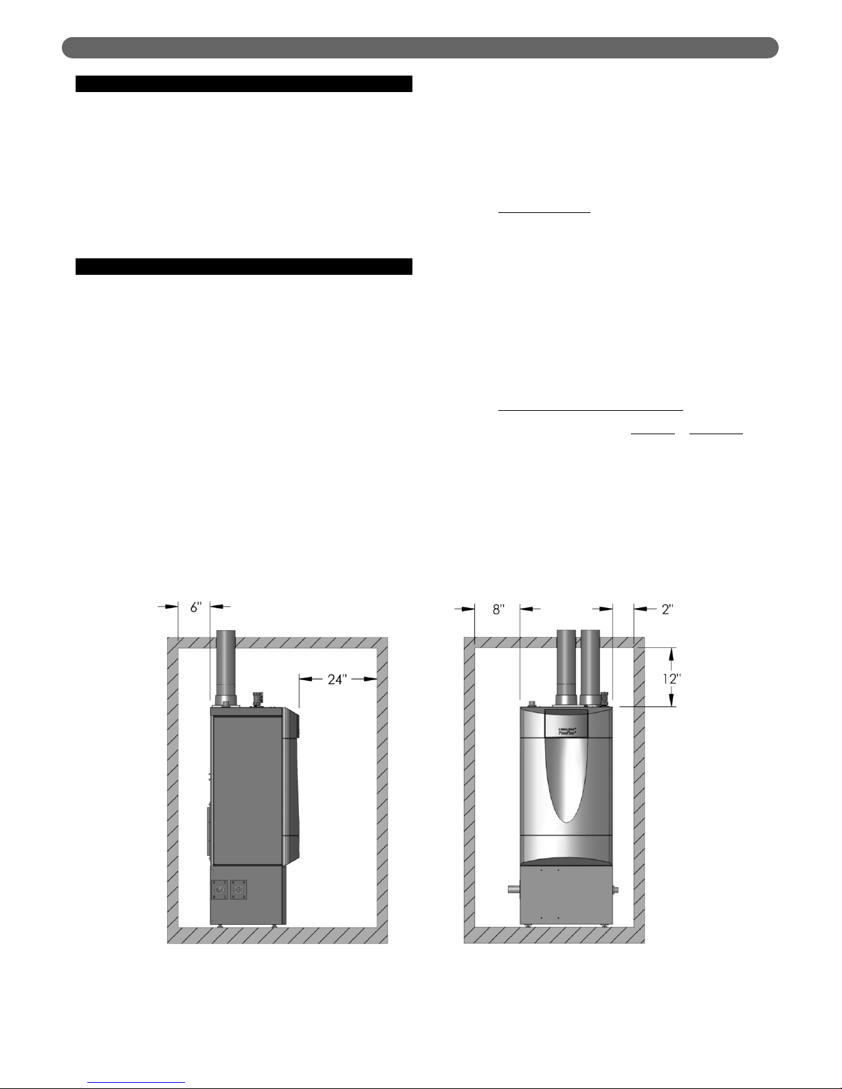
C. ACCESSIBILITY CLEARANCES
1. The PureFire boiler is certified for closet installations
with zero clearance to combustible construction. In
addition, it is design certified for use on combustible
floors.
2. Figure 1.1 shows the minimum recommended
clearances to allow reasonable access to the boiler for
Models PFW-200 and PFW-399. However, local
codes or special conditions may require greater
clearances.
E. D. COMBUSTION AND
VENTILATION AIR
D. COMBUSTION AND VENTILATION AIR
1. The PureFire boiler is designed for operation with
combustion air piped directly to the boiler from
outside the building (sealed combustion). Combustion
air may be supplied from within the building only if
adequate combustion air and ventilation air is
provided in accordance with the National Fuel Gas
Code or applicable provisions of the local building
code. Subsections 3 through 10 as follows are based
on the National Fuel Gas Code requirements.
2. If the combustion air is piped directly to the boiler
from outside the building, no additional combustion
or ventilation air is required. Otherwise, follow the
National Fuel Gas Code recommendations
summarized in subsections 3 through 10.
3. Required Combustion Air Volume: The total required
volume of indoor air is to be the sum of the required
volumes for all appliances located within the space.
Rooms communicating directly with the space in
which the appliances are installed and through
combustion air openings sized as indicated in
Subsection 3 are considered part of the required
volume. The required volume of indoor air is to be
determined by one of two methods.
a. Standard Method
: The minimum required volume
of indoor air (room volume) shall be 50 cubic feet
per 1000 BTU/Hr (4.8 m3/kW). This method is to
be used if the air infiltration rate is unknown or if
the rate of air infiltration is known to be greater
than 0.6 air changes per hour. As an option, this
method may be used if the air infiltration rate is
known to be between 0.6 and 0.4 air changes per
hour. If the air infiltration rate is known to be
below 0.4 then the Known Air Infiltration Rate
Method must be used. If the building in which this
appliance is to be installed is unusually tight, PB
Heat recommends that the air infiltration rate be
determined.
b. Known Air Infiltration Rate Method
:
where:
I
fan
= Input of the fan assisted appliances
assisted in Btu/hr
ACH = air change per hour (percent of the
volume of the space exchanged per
hour, expressed as a decimal)
Note: These calculations are not to be used for
infiltration rates greater than 0.60 ACH.
Figure 1.1: Minimum Accessibility Clearances – PFW-200 & PFW-399
3
PREINSTALLATION
15 ft
3
I
fan
ACH 1000
Btu
/
hr
Required Volume
fan
=
⎛
⎜
⎝
⎛
⎜
⎝
Page 6
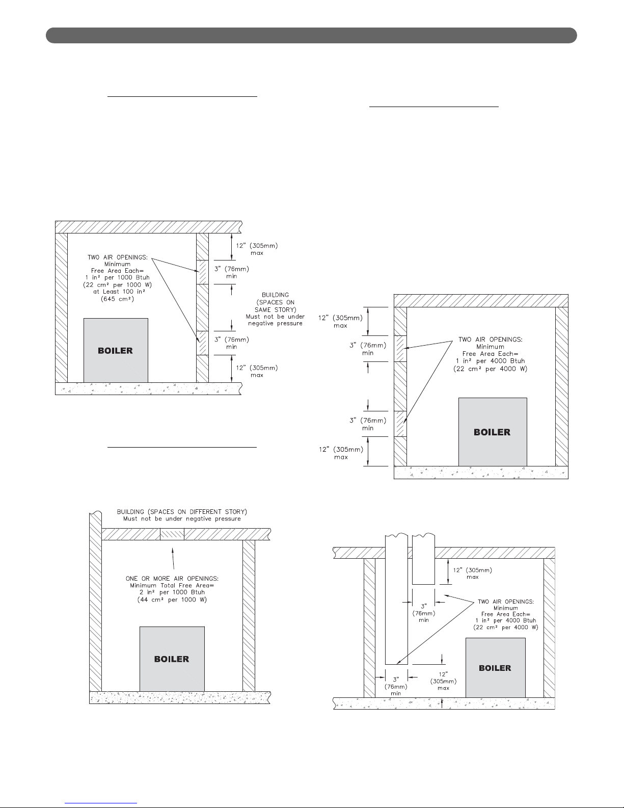
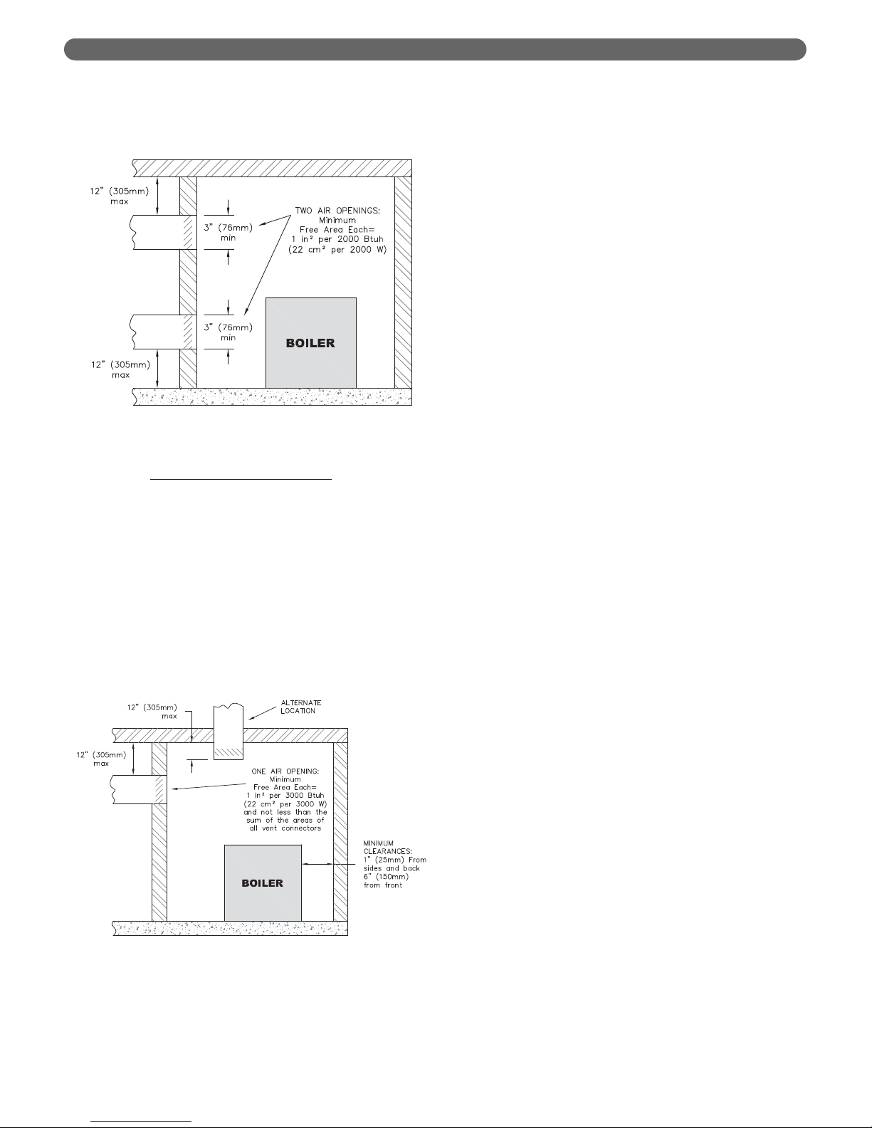
4. Indoor Air Opening Size and Location: Openings
connecting indoor spaces shall be sized and located as
follows:
a. Combining Spaces on the Same Floor
: Provide
two permanent openings communicating with
additional spaces that have a minimum free area
of 1 in
2
per 1000 Btu/hr (22 cm2per 1000 W) of
the total input rating of all gas fired equipment but
not less than 100 in
2
(645 cm2). One opening is to
begin within 12 inches (305 mm) from the top of
the space and the other is to begin within 12
inches (305 mm) from the floor. The minimum
dimension of either of these openings shall be 3
inches (76 mm), see Figure 1.2 for an illustration
of this arrangement.
b. Combining Spaces on Different Floors
: Provide
one or more permanent openings communicating
with additional spaces that have a total minimum
free area of 2 in
2
per 1000 Btu/hr (44 cm2per
1000 W) of total input rating of all equipment, see
Figure 1.3 for an illustration of this arrangement.
5. Outdoor Combustion Air: Outdoor combustion air is
to be provided through one or two permanent
openings. The minimum dimension of these air
openings is 3 inches (76 mm).
a. Two Permanent Opening Method
: Provide two
permanent openings. One opening is to begin
within 12 inches (305 mm) of the top of the space
and the other is to begin within 12 inches (305
mm) of the floor. The openings are to
communicate directly or by ducts with the
outdoors or with spaces that freely communicate
with the outdoors. The size of the openings shall
be determined as follows:
i. Where communicating directly or through
vertical ducts with the outdoors each opening
shall have a minimum free area of 1 in2 per
4000 Btu/hr (22 cm
2
per 4000 W) of total
input rating for all equipment in the space, see
Figure 1.4 for openings directly
communicating with the outdoors or Figure
1.5 for openings connected by ducts to the
outdoors.
Figure 1.2: Air Openings – All Air from Indoors
on the Same Floor
Figure 1.3: Air Openings – All Air from Indoors
on Different Floors
Figure 1.4: Air Openings – All Air Directly from
Outdoors
Figure 1.5: Air Openings – All Air from Outdoors
through Vertical Ducts
4
PREINSTALLATION
Page 7
ii. Where communicating with the outdoors through
horizontal ducts, each opening shall have a
minimum free area of 1 in
2
per 2000 Btu/hr (22
cm2per 2000 W) of total rated input for all
appliances in the space, see Figure 1.6.
b. One Permanent Opening Method
: Provide one
permanent opening beginning within 12 inches
(305 mm) of the top of the space. The opening
shall communicate directly with the outdoors,
communicate through a vertical or horizontal duct,
or communicate with a space that freely
communicates with the outdoors. The opening
shall have a minimum free area of 1 in
2
per 3000
Btu/hr of total rated input for all appliances in the
space and not less than the sum of the crosssectional areas of all vent connectors in the space.
The gas-fired equipment shall have clearances of
at least 1 inch (25 mm) from the sides and back
and 6 inches (150 mm) from the front of the
appliance, see Figure 1.7 for this arrangement.
6. Combination Indoor and Outdoor Combustion Air: If
the required volume of indoor air exceeds the
available indoor air volume, outdoor air openings or
ducts may be used to supplement the available indoor
air provided:
a. The size and location of the indoor openings
comply with Subsection 3.
b. The outdoor openings are to be located in
accordance with Subsection 4.
c. The size of the outdoor openings are to be sized
as follows:
where:
A
req
= minimum area of outdoor openings.
A
full
= full size of outdoor openings calculated
in accordance with Subsection 4.
V
avail
= available indoor air volume
V
req
= required indoor air volume
7. Engineered Installations: Engineered combustion air
installations shall provide an adequate supply of
combustion, ventilation, and dilution air and shall be
approved by the authority having jurisdiction.
8. Mechanical Combustion Air Supply:
a. In installations where all combustion air is
provided by a mechanical air supply system, the
combustion air shall be supplied from the
outdoors at the minimum rate of 0.35 ft
3
/min per
1000 Btu/hr (0.034 m
3
/min per 1000 W) of the
total rated input of all appliances in the space.
b. In installations where exhaust fans are installed,
additional air shall be provided to replace the
exhaust air.
c. Each of the appliances served shall be interlocked
to the mechanical air supply to prevent main
burner operation when the mechanical air supply
system is not in operation.
d. In buildings where the combustion air is provided
by the mechanical ventilation system, the system
shall provide the specified combustion air rate in
addition to the required ventilation air.
9. Louvers & Grills:
a. The required size of openings for combustion,
ventilation, and dilution air shall be based on the
net free area of each opening.
i. Where the free area through a louver or grille
is known, it shall be used in calculating the
opening size required to provide the free area
specified.
ii. Where the free area through a louver or grille
is not known, it shall be assumed that wooden
louvers will have 25% free area and metal
louvers and grilles will have 75% free area.
iii. Non-motorized dampers shall be fixed in the
open position.
b. Motorized dampers shall be interlocked with the
equipment so that they are proven in the full open
position prior to ignition and during operation of
the main burner.
Figure 1.6: Air Openings – All Air from Outdoors
through Horizontal Ducts
Figure 1.7: Air Openings – All Air from Outdoors
through One Opening
5
PREINSTALLATION
Page 8
i. The interlock shall prevent the main burner
from igniting if the damper fails to open during
burner startup.
ii. The interlock shall shut down the burner if the
damper closes during burner operation.
10. Combustion Air Ducts:
a. Ducts shall be constructed of galvanized steel or
an equivalent corrosion-resistant material.
b. Ducts shall terminate in an unobstructed space,
allowing free movement of combustion air to the
appliances.
c. Ducts shall serve a single space.
d. Ducts shall not serve both upper and lower
combustion air openings where both such
openings are used. The separation between ducts
serving upper and lower combustion air openings
shall be maintained to the source of combustion
air.
e. Ducts shall not be screened where terminating in
an attic space.
f. Horizontal upper combustion air ducts shall not
slope downward toward the source of the
combustion air.
g. The remaining space surrounding a chimney liner,
gas vent, special gas vent, or plastic piping
installed within a masonry, metal, or factory built
chimney shall not be used to supply combustion
air unless it is directly piped to the air inlet as
shown in Figure 3.9.
h. Combustion air intake openings located on the
exterior of buildings shall have the lowest side of
the combustion air intake opening at least 12
inches (305 mm) above grade.
11. Refer to Section 3 of this manual, Venting & Air Inlet
Piping, for specific instructions for piping the exhaust
and combustion air.
E. PLANNING THE LAYOUT
1. Prepare sketches and notes showing the layout of the
boiler installation to minimize the possibility of
interferences with new or existing equipment, piping,
venting and wiring.
2. The following sections of this manual should be
reviewed for consideration of limitations with
respect to:
a. Venting and Air Inlet Piping: Section 3
b. Water Piping: Section 4
c. Fuel Piping: Section 5
d. Condensate Removal: Section 6
e. Electrical Connections: Section 7
f. Boiler Control: Section 8
g. Boiler Dimensions and Ratings: Section 12
6
PREINSTALLATION
Do not install this boiler where gasoline or other
flammable liquids or vapors are stored or are in use.
WARNING
This boiler is certified as an indoor appliance. Do not
install this boiler outdoors or locate where it will be
exposed to freezing temperatures.
WARNING
Do not install this boiler in the attic.
WARNING
Page 9

7
BOILER SET-UP
A. GENERAL
1. PureFire boilers are intended for installation in an area
with a floor drain or in a suitable drain pan. Do not
install any boiler where leaks or relief valve discharge
will cause property damage.
2. The PureFire boiler is not intended to support external
piping. All venting and other piping should be
supported independently of the boiler.
3. Install the boiler level to prevent condensate from
backing up inside the boiler.
B. FLOOR STANDING INSTALLATION
1. For floor standing installations, use the leveling feet to
assure that the boiler is completely level. This will
prevent condensate from backing up in the boiler.
2. Be sure to leave adequate space for condensate
piping or a pump if required.
2. BOILER SET-UP
This boiler must be installed level to prevent
condensate from backing up inside the boiler.
CAUTION
Page 10

A. GENERAL
1. Install the PureFire boiler venting system in
accordance with these instructions and with the
National Fuel Gas Code, ANSI Z223.1/NFPA 54,
CAN/CGA B149, and/or applicable provisions of local
building codes.
2. The PureFire boiler is a direct vent appliance and is
ETL Listed as a Category IV appliance with Intertek
Testing Laboratories, Inc.
3. Sources of combustion air contaminated with chlorine,
ammonia or alkali agents must be avoided. Do not
install this boiler near a swimming pool, hot tubs or
laundry. Do not store chemicals near the boiler.
B. APPROVED MATERIALS
1. Table 3.1 lists approved materials for vent pipe (and
adhesives where applicable). Use only these materials
for exhaust vent piping.
2. PVC pipe and fittings are not to be used for venting in
confined spaces such as closet installations. Use only
CPVC or approved polypropylene (InnoFlue or
PolyPro) vent pipe under these conditions.
3. Cellular core piping is approved for inlet air piping only.
* PVC pipe/fittings are not to be used for venting within confined spaces.
Notice: Installations in Canada require compliance with
ULC S636 – Standard for Type BH Gas Venting Systems.
C. EXHAUST VENT/AIR INTAKE PIPE
LOCATION
1. Install vent piping before installing water, fuel, or
condensate piping. Working from largest to smallest
diameter reduces the complexity of piping
interferences.
2. Vent and air intake piping is to be installed so that
there is sufficient access for routine inspection as
required in Section 11 of this manual.
3. The vent piping for this boiler is approved for zero
clearance to combustible construction. However, a fire
stop must be used where the vent pipe penetrates
walls or ceilings.
4. The PureFire boiler, like all high efficiency, gas-fired
appliances, is likely to produce a vapor plume due to
condensation. Surfaces near the vent termination will
likely become coated with condensation.
5. The maximum combined vent and air inlet vent
length for the PureFire boiler is about 200 equivalent
feet (60 m). Be sure that the boiler is located such that
the maximum vent length is not exceeded.
6. Air Intake Pipe Location – Sidewall Venting:
a. Provide 1 foot (30 cm) clearance from the bottom
of the air intake pipe to the level of maximum
snow accumulation. Snow removal may be
necessary to maintain clearances.
b. Do not locate air intake pipe in a parking area
where machinery may damage the pipe.
c. Maintain a minimum of 8” horizontal distance
between exhaust vent and the air intake.
Increasing this distance minimizes the potential for
contamination of the inlet air with exhaust.
3. VENTING & AIR INLET PIPING
The venting system for this product is to be installed in
strict accordance with these venting instructions.
Failure to install the vent system properly may result in
severe personal injury, death or major property damage.
WARNING
This vent system operates under positive pressure.
Vent connectors serving appliances vented by
natural draft shall not be connected into any portion
of this venting system. Failure to comply may result
in serious injury, death or major property damage.
WARNING
Only materials listed in Table 3.1 are approved for use
with PureFire boilers. Use only these components in
accordance with these instructions. Failure to use
the correct material may result in serious injury,
death, or major property damage.
WARNING
Use of cellular core pipe for any exhaust vent
component is prohibited. Use of cellular core pipe
may result in severe personal injury, death, or major
property damage.
WARNING
If the maximum equivalent vent length is exceeded,
the maximum burner input rate may be reduced.
NOTICE
8
VENTING & AIR INLET PIPING
Table 3.1: Approved Materials for Exhaust Vent Pipe
Description Material
Conforming to
Standard
Exhaust Vent Pipe &
Fittings
PVC (Sch 40 or 80)*
ANSI/ASTM D1785
CPVC (Sch 40 or 80) ANSI/ASTM D1785
PVC-DWV*
ANSI/ASTM D2665
FasNSeal
®
UL1738 & ULC S636
PolyPro
®
ULC-S636
InnoFlue
®
UL1738 & ULC S636
Pipe Cement
(PVC & CPVC Only)
PVC/CPVC Cement ANSI/ASTM D2564
Page 11
9
VENTING & AIR INLET PIPING
d. If the vent pipe and air inlet pipe terminations
penetrate the wall at the same level the minimum
distance between them is 8" center-to-center.
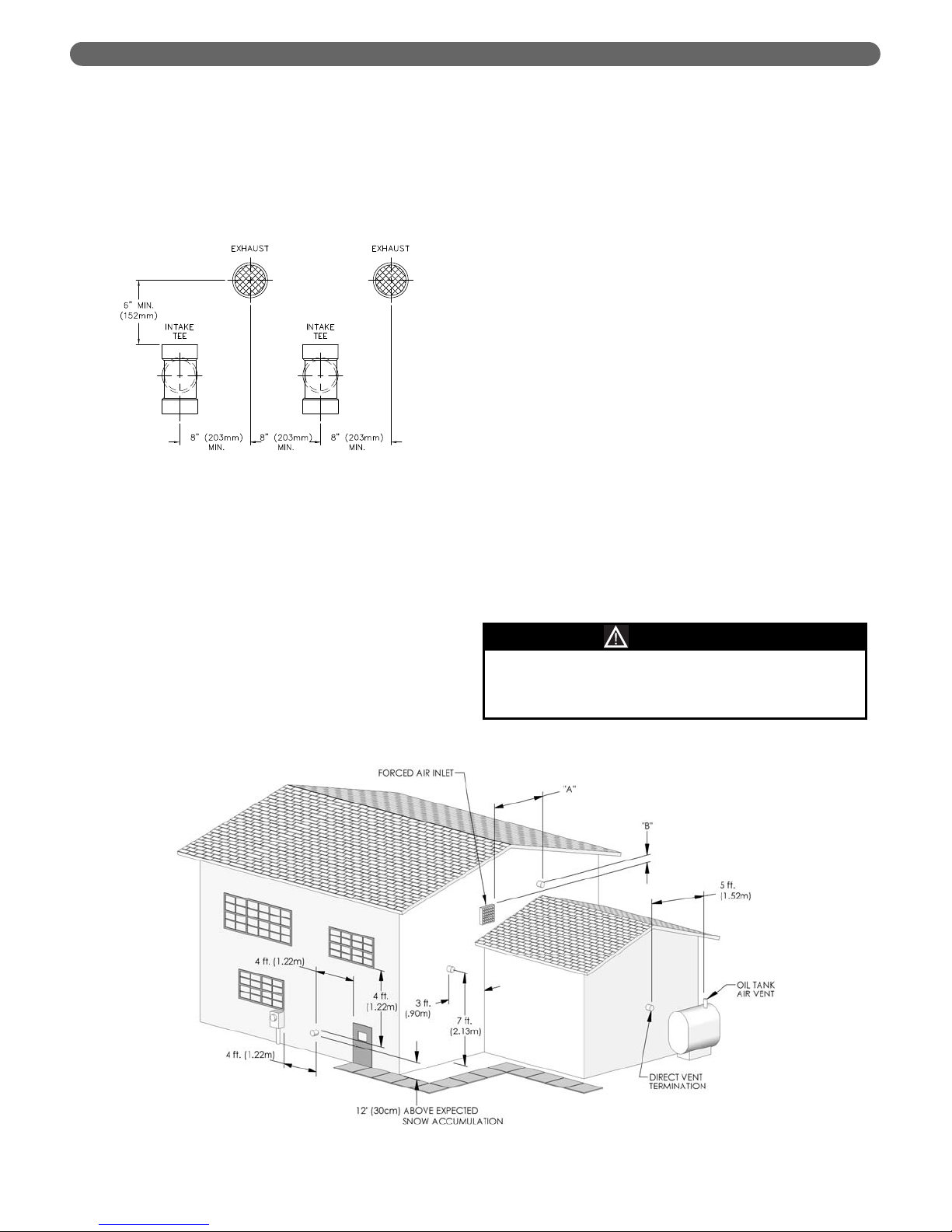
e. Multiple Boiler Installations:
• The minimum horizontal distance between the
inlet of one boiler to the exhaust of an adjacent
boiler is 8” center-to-center. In addition, the
minimum vertical distance between the exhaust
air and air inlet is 6”. See Figure 3.1.
• DO NOT CONNECT air inlet pipes together.
Air inlet must be piped separately to prevent
drawing exhaust and/or moist condensate back
through the blower of an idle boiler.
• If multiple boilers are installed without piping
the air intake to outdoors, care must be taken
to be sure that the boiler room is well
ventilated and is not negatively pressurized
when the boilers or other air moving
equipment are in operation.
f. The exhaust outlet of the vent pipe should not be
angled any more than 5º from horizontal.
g. Precautions should be taken to prevent
recirculation of flue gases to the air inlet pipe of
the boiler or other adjacent appliances.
7. Sidewall Venting Configuration:
a. See Figure 3.2 for an illustration of clearances for
location of exit terminals of direct-vent venting
systems.
• The boiler vent system shall terminate a least 3
feet (0.9 m) [“B” Figure 3.2] above any forced
air inlet located within 10 feet (3 m) [“A” Figure
3.2]. Note: This does not apply to the
combustion air intake of a direct vent appliance.
• Provide a minimum of 4 feet (1.22 m)
distance from any door, operable window, or
gravity intake into any building.
• Provide a minimum of 1 foot (30 cm) clearance
from the bottom of the exit terminal above the
expected snow accumulation level. Snow
removal may be required to maintain clearance.
• Provide a minimum of 4 feet (1.22 m)
horizontal clearance from electrical meters, gas
meters, gas regulators, and relief equipment. In
no case shall the exit terminal be above or
below the aforementioned equipment unless
the 4 foot horizontal distance is maintained.
• Do not locate the exhaust exit terminal over
public walkways where condensate could drip
and create a hazard or nuisance.
• When adjacent to public walkways, locate the
exit terminal at least 7 feet above grade.
• Do not locate the exhaust termination directly
under roof overhangs to prevent icicles from
forming or recirculation of exhaust gases from
occurring.
• Provide 3 feet clearance from the inside corner
of adjacent walls.
Figure 3.1: Vent Pipe Spacing for Multiple PureFire
Boilers
Figure 3.2: Exit Terminal Location for Mechanical Draft and Direct-Vent Venting Systems
Condensing flue gases can freeze on exterior
building surfaces which may cause discoloration and
degradation of the surfaces.
CAUTION
Page 12
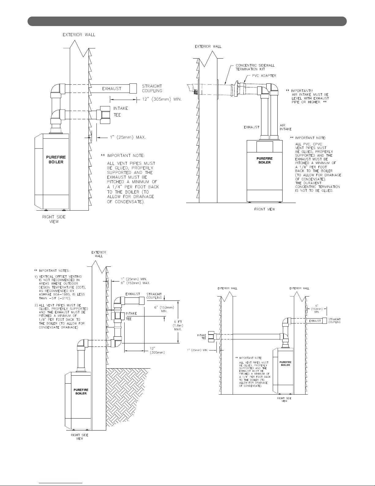
Figure 3.3: Standard Exhaust & Air Inlet Pipe
Terminations
Figure 3.4: Offset Exhaust & Air Inlet Terminations
10
VENTING & AIR INLET PIPING
Figure 3.5: Optional Concentric Vent Kit
Installation
Figure 3.6: Exhaust & Air Inlet on Opposite Walls
Page 13

b. Figure 3.3 and 3.4 show approved sidewall venting
configurations using the standard fittings supplied.
c. Figure 3.4 is only approved for locations in which
the outdoor temperature is above -5°F (-21°C) in
accordance with ASHRAE 90A-1980
recommendations.
d. Figure 3.5 shows an approved sidewall vent
configuration using an optional concentric vent
termination kit. 3” (54498) or 4” (54499).
e. Figure 3.6 shows an approved configuration with
the exhaust termination and inlet air piped to
opposite walls
f. Figure 3.7 shows an approved configuration with
combustion air supplied from indoors. Refer to
Section 1.D to be sure that there is adequate air
for combustion and ventilation at the boiler.
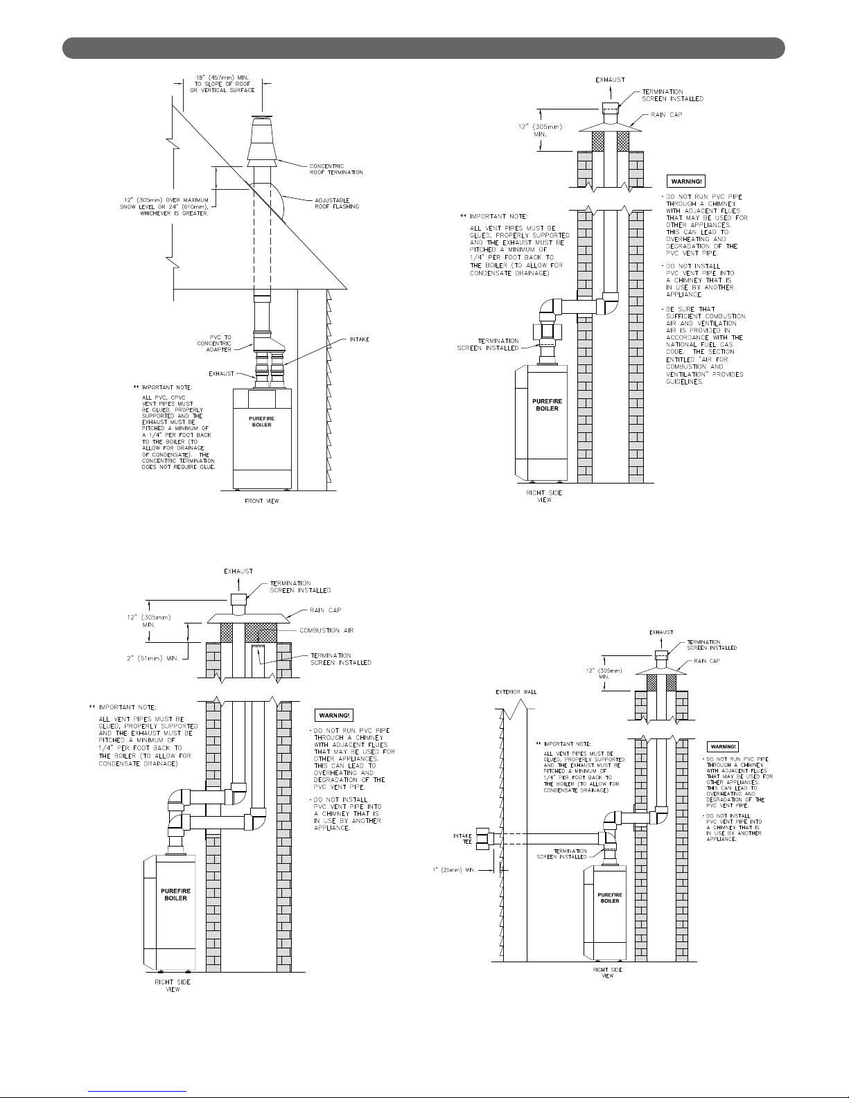
8. Vertical Venting Configuration:
a. Figure 3.8 shows the approved venting
configuration for vertical venting using the
standard fittings supplied.
• Locate the air intake pipe inlet 12" above the
expected snow accumulation on the roof
surface or 24" above the roof surface,
whichever is greater.
• Locate the end of the exhaust vent pipe a
minimum of 12" above the inlet to the air
intake pipe.
b. Figure 3.9 shows an approved vertical vent
configuration using the optional concentric vent
termination kit. 3" (54500) or 4" (54501)
c. Figure 3.10 shows an option for routing the
exhaust through an unused chimney while
bringing combustion air from the space
surrounding the vent pipe.
d. Figure 3.11 shows an option for routing the
exhaust through an unused chimney with the
combustion air supplied from inside the building.
Be sure to note the requirements for combustion
air as listed under Section 1.D. "Combustion and
Ventilation Air". These requirements are in
accordance with the National Fuel Gas Code.
e. Figure 3.12 shows an option for routing the
exhaust through an unused chimney in which
combustion air is piped in from a sidewall.
11
VENTING & AIR INLET PIPING
Figure 3.7: Sidewall Exhaust with Indoor Air
Figure 3.8: Standard Vertical Vent Installation
DO NOT USE the indoor air configuration shown in
Figure 3.7 if there are exhaust fans or other air
moving equipment (furnaces, heating boilers, etc.) in
operation in the same location. Damage to
equipment may occur from drawing combustion air
back through and idle appliance.
CAUTION
Page 14
12
VENTING & AIR INLET PIPING
Figure 3.9: Concentric Vertical Vent Installation
Figure 3.10: Venting Through A Chimney Using
Outdoor Air
Figure 3.12: Venting Through A Chimney Using
Sidewall Outside Air
Figure 3.11: Venting Through A Chimney Using
Indoor Air
Page 15

13
D. EXHAUST VENT/AIR INTAKE PIPE SIZING
1. PureFire boiler model PFW-200 is to be installed using
3” Schedule 40 or 80 PVC or CPVC piping using the
provided vent adapter. PureFire boiler model PFW-399
is to be installed using 4” Schedule 40 or 80 PVC or
CPVC using the vent adapter provided..
2. Polypropylene vent systems may be installed using
optional InnoFlue
®
or PolyPro®vent adapters. Table
3.2 shows the appropriate PB Heat stock codes.
Contact your PB Heat Representative for more
information on this option.
3. Combined systems using separate polypropylene
exhaust & air inlet pipes which transition to concentric
can also be installed. Contact your Centrotherm or
DuraVent representative for more information.
4. The total combined length of exhaust vent and air
intake piping is 200 equivalent feet (60 m).
a. The equivalent length of elbows, tees and other
fittings are listed in Table 3.3.
b. The equivalent length can be calculated as follows.
This is well below the 200 feet maximum
equivalent length. If the total is above 200
equivalent feet, alternate boiler locations or
exhaust penetration location should be considered.
E. EXHAUST VENT/AIR INTAKE
INSTALLATION
1. Figure 12.1 shows the exhaust connection on top of
the boiler, near the rear in the center.
a. The exhaust connection for the PFW-200 is 3”
male CPVC pipe. The exhaust connection for the
PFW-399 is 4” male CPVC pipe..
b. These connections are to be joined with suitable
PVC/CPVC adhesives in accordance with
manufacturers’ instructions.
2. The Air Intake connection is to the right of the exhaust.
3. Both connections are clearly marked.
4. Remove all burrs and debris from the joints and fittings.
5. Horizontal lengths of exhaust vent must be installed with
a slope of not less than 1/4" per foot (21 mm per meter)
toward the boiler to allow condensate to drain from the
vent pipe. If the vent pipe must be piped around an
obstacle that causes a low point in the piping, a drain
with an appropriate trap must be installed.
6. All piping must be fully supported. Use pipe hangers
at a minimum of 4 foot (1.22 meter) intervals to
prevent sagging of the pipe.
7. Exhaust and air inlet piping is to be supported
separately and should not apply force to the boiler.
8. Penetration openings around the vent pipe and air
intake piping are to be fully sealed to prevent exhaust
gases from entering building structures.
9. PVC & CPVC Piping:
a. Use only solid PVC or CPVC Schedule 40 or 80
pipe for exhaust venting. Cellular core PVC or
CPVC is not approved for exhaust vent.
b. All joints in vent pipe, fittings, attachment to the
boiler stub, and all vent termination joints must be
properly cleaned, primed and cemented. Use only
cement and primer approved for use with PVC or
CPVC pipe that conforms to ANSI/ASTM D2564.
c. A straight coupling is provided with the boiler to
be used as an outside vent termination. One of
the two screens is to be installed to prevent birds
or rodents from entering.
d. An air intake tee is provided with the boiler to be
used as an outside air intake termination. A screen
is to be installed to prevent birds or rodents from
entering.
VENTING & AIR INLET PIPING
This appliance uses a positive pressure venting
system. All joints must be sealed completely to
prevent leakage of flue products into living spaces.
Failure to do this may result in severe personal injury,
death or major property damage.
WARNING
Fitting Description Equivalent Length
Elbow, 90° Short Radius 5 feet
Elbow, 90° Long Radius 4 feet
Elbow, 45° Short Radius 3 feet
Coupling 0 feet
Air Intake Tee 0 feet
Stainless Steel Vent Kit 1 foot
Concentric Vent Kit 3 feet
Table 3.3: Equivalent Length of Fittings
Exhaust Air Inlet Total
Straight Length of Pipe 50' 50' 100'
90° Elbows, SR 2 x 5'= 10' 1 x 5' = 5' 15'
45° Elbows, SR 2 x 3' = 6' 6'
Conc. Vent Termination 1 x 3' = 3' 3'
Total 124'
Table 3.4: Sample Equivalent Length Calculation
Table 3.2: Polypropylene Vent Adapters
Boiler
Model
Centrotherm
InnoFlue
®
DuraVent
Pol yPro
®
PFW-200 54632 54630
PFW-399 54633 54631
Page 16

14
VENTING & AIR INLET PIPING
e. Table 3.5 shows optional concentric air
intake/exhaust terminations that are available
separately from your PB Heat distributor for use
with PureFire boilers
f. Refer to Figures 3.3 to 3.6 for sidewall venting
options using PVC or CPVC pipe.
g. Refer to Figures 3.7 & 3.8 for vertical venting
options using PVC or CPVC pipe.
F. EXHAUST TAPPING FOR VENT SAMPLE
To properly install the PureFire boiler, carbon dioxide
(CO
2
) and carbon monoxide (CO) readings must be
determined from a sample of combustion products.
1. To do this in PVC or CPVC vent pipe, a hole must be
drilled in the exhaust vent pipe:
a. Drill a 21/64” diameter hole in the exhaust vent
pipe positioned so that the combustion analyzer
probe can be inserted between 6” and 12” from
the boiler connection.
b. Tap the hole with a 1/8” NPT pipe tap.
c. Us a 1/8” NPT PVC or Teflon Pipe Plug to seal
the hole.
2. InnoFlue
®
and PolyPro®vent systems offer test port
fittings for obtaining a sample of combustion products.
See your Centrotherm or DuraVent Representative for
recommendations.
3. See Section 9.D.8 for instructions on taking
combustion readings.
G. BOILER REMOVAL FROM COMMON
VENTING SYSTEM
At the time of removal of an existing boiler, follow these
steps with each appliance remaining connected to the
common venting system placed in operation, while the
other appliances remaining connected to the common
venting system are not in operation:
Retrait de la chaudière d’un système d’évacuation
commun. Au moment de retirer une chaudière existante,
il est important de suivre les étapes suivantes pour chaque
appareil raccordé au système d’évacuation commun qui
sont en service, alors que les autres appareils demeurant
raccordés au système d’évacuation commun ne sont pas
en service :
1. Seal any unused openings in the common venting
system.
Sceller toute ouverture du système d’évacuation
commun non utilisée.
2. Visually inspect the venting system for proper size and
horizontal pitch and determine there is no blockage or
restriction, leakage, corrosion and other deficiencies
which could cause an unsafe condition.
Effectuer un contrôle visuel du système d’évacuation
pour vérifier la taille et la pente horizontale et
s’assurer qu’il n’existe aucun blocage ou obstruction,
fuite, corrosion ni tout autre problème pouvant
menacer la sécurité.
3. Insofar as is practical, close all building doors and
windows and all doors between the space in which
the appliances remaining connected to the common
venting system are located and other spaces of the
building.
Dans la mesure du possible, fermer toutes les portes
et fenêtres de l’immeuble ainsi que toutes les portes
entre l’espace dans lequel les appareils qui demeurent
raccordés au système d’évacuation commun se
trouvent et le reste de l’immeuble.
4. Turn on any clothes dryers and any appliance not
connected to common venting system. Turn on any
exhaust fans, such as range hoods and bathroom
exhausts, so they will operate at maximum speed. Do
not operate a summer exhaust fan.
Mettre en marche les sécheuses et tout autre appareil
non raccordé au système d’évacuation commun.
Mettre en marche tous les ventilateurs aspirant, tels
que les hottes de cuisinière et les ventilateurs de salle
de bain, en les faisant fonctionner à vitesse maximum.
5. Close fireplace dampers.
Ne pas faire fonctionner les ventilateurs aspirant d’été.
Fermer les registres de foyers.
6. Place in operation the appliance being inspected.
Follow the lighting instructions. Adjust thermostat so
appliance will operate continuously.
Mettre en service l’appareil à inspecter. Suivre les
instructions concernant l’allumage. Régler le
thermostat afin que l’appareil fonctionne sans arrêt.
7. Test for spillage at the draft hood relief opening after 5
minutes of main burner operation. Use the flame of a
match or candle, or smoke from a cigarette, cigar, or
pipe.
Vérifier toute fuite à l’orifice de décharge du coupetirage après que le brûleur ait fonctionné pendant 5
minutes. Utiliser la flamme d’une allumette ou d’une
chandelle ou encore la fumée d’une cigarette, d’un
cigare ou d’une pipe.
Boiler
Model
Description
Stock
Code
PFW-200
Sidewall Vent Termination Kit –
Polypro 3PPS-HK
54498
Vertical Vent Termination Kit –
Polypro 3PPS-VK
54500
PFW-399
Sidewall Vent Termination Kit –
Polypro 3PPS-HK
54499
Vertical Vent Termination Kit –
Polypro 3PPS-VK
54501
Table 3.5: Concentric Vent Termination Kits
Page 17
15
A. GENERAL
1. Size water supply and return piping in accordance
with system requirements. Do not use smaller
diameter piping than the boiler connections.
2. If the PureFire boiler is used to replace an existing
boiler, make sure that the system piping is thoroughly
cleaned and free from debris before installation.
3. In systems where sediment may exist, install a strainer
in the boiler return piping to prevent large particles
and pipe scale from entering the boiler heat
exchanger. Use a large mesh screen in the strainer.
4. Install this boiler so that the gas ignition system
components are protected from water (dripping, spraying,
etc.) during operation and service (pump replacement,
condensate trap cleaning, sensor replacement, etc.).
5. The PureFire boiler is supplied with a default tank
temperature setpoint of 120°F (49°C). However, the
setpoint can be set as high as 158°F (70°C) which can
potentially cause scald injury. If the tank temperature
is set to above 120°F (49°C), PB Heat recommends
the use of a mixing valve to provide lower
temperature water to faucets and shower heads.
B. OPERATING PARAMETERS
1. The PureFire boiler is designed to operate in an open
loop domestic water heating system under forced
circulation with a water storage tank. The system must
be completely filled with water at all times and water
must be circulating through the boiler while the unit is
firing for it to operate effectively.
2. The minimum system pressure is 14.5 PSI (69 kPa).
3. Table 4.1 lists the minimum flow rates for each
PureFire model.
4. Table 4.2 provides the water volume of the heat
exchanger including the supply and return pipes that
are attached at the factory.
5. The required temperature rise and the standard
circulating pump are sized based on the heating of
potable water with a hardness of 5 to 25 grains per
gallon and a total dissolved solids not exceeding 350
ppm. Consult the manufacturer when heating potable
water exceeding these specifications.
Heating of high hardness and/or high total dissolved
solids water may require a larger circulating pump,
and a revised temperature rise specification based on
the water chemistry of the water to be heated.
Water with a hardness of less than 5 grains per gallon
will usually have a pH which can be aggressive and
corrosive causing non-warrantable damage to the
pump, and associated piping. Corrosion due to water
chemistry generally shows up first in the hot water
system because heated water increases the rate of
corrosive chemical reactions.
C. SYSTEM COMPONENTS
1. Pressure/Temperature Gauge: A combination
pressure/temperature gauge is provided with each
boiler to be mounted in the piping from the boiler
supply to the system as shown in Figure 4.1. Most
local codes require this gauge.
2. Potable Water Expansion Tank: An expansion tank is
required to provide room for expansion of the heating
medium (water or glycol solution). Consult the expansion
tank manufacturer's instructions for specific information
regarding installation. The expansion tank is to be sized
for the required system volume and capacity.
3. Y-Type Strainer or Filter Ball
®
Valve: PB Heat
recommends the use of a strainer device in the system
to prevent dirt or sediment from clogging the heat
exchanger. A 20 mesh stainless steel screen is
adequate to protect the heat exchanger. The strainer
should be cleaned often in the first several months of
operation. The Filter Ball
®
Valve from Jomar
International incorporates a strainer into a ball valve
which allows the technician to isolate the water circuit
while cleaning the strainer.
4. WATER PIPING & CONTROLS
Table 4.1: Minimum Flow Rate
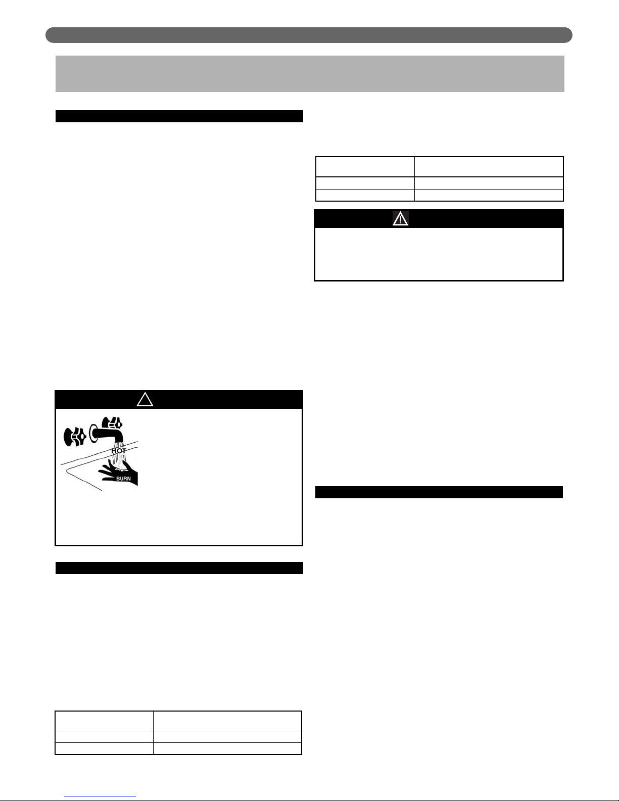
Water temperatures over 125°F
(52°C) can cause severe burns
instantly, or death from scalds.
Children, disabled, and elderly
are at the highest risk of being
scalded.
See instruction manual before
setting temperature at water heater.
Feel water before bathing or showering.
Temperature limiting valves are available, see
manual.
DANGER
!
Table 4.2: Heat Exchanger Water Capacity
WATER PIPING AND CONTROLS
Water temperature rise and maximum flow data is
based on heating potable water with a hardness of 5
to 25 grains per gallon and total dissolved solids not
exceeding 350 ppm.
NOTICE
PureFire
Model
Total Water Capacity
Gallons (Liters)
PFW-200 1.19 (4.50)
PFW-399 2.60 (9.84)
PureFire
Model
Minimum Water Flow Rate
GPM (LPM)
PFW-200 5.5 (20.8)
PFW-399 13.2 (50.0)
Page 18
16
WATER PIPING AND CONTROLS
4. Back Flow Preventer: A back flow preventer (check
valve) is required by some jurisdictions to prevent water
in the system from backing up into the city water supply.
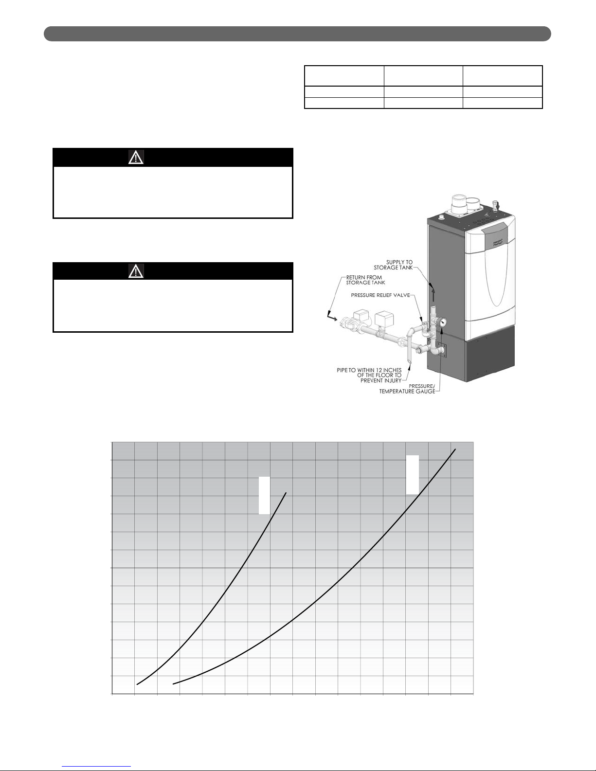
5. Pressure Relief Valve: The boiler pressure relief valve
is shipped separately for field installation. It is
extremely important to mount this relief valve in the
vertical position on the boiler supply pipe (toward the
front of the boiler).
The valve is to be installed as shown in Figure 4.1
Pipe the discharge of the relief valve to within 12"
(305 mm) of the floor and close to a floor drain.
Provide piping that is the same size or larger than the
relief valve outlet.
6. Pump: The boiler pump is to be sized to overcome the
pressure drop of the system while providing the flow
required by the boiler.
a. The pump should be sized based on gross output of
the boiler. Table 4.3 shows the Boiler Output as
reported to the Hydronics Institute Section of AHRI.
b. The required flow is calculated based on the design
temperature difference from the return to the supply of
the boiler. For a PFW-200 with a design temperature
difference of 20°F the calculation is as follows:
Output 182,000
Required Flow =
________=_________
= 18.2 GPM
Δ
T x 500 20 x 500
Figure 4.1: Relief Valve Installation - PFW-200 &
PFW-399
PureFire
Model
Max. Boiler Input
Btu/hr (kW)
Gross Output
Btu/hr (kW)
PFW-200 199,000 (58.3) 183,000 (53.6)
PFW-399 399,000 (116.9) 373,000 (109.3)
Table 4.3: Boiler Inputs and Outputs
Pipe the discharge of the relief valve as close as
possible to the floor and away from high traffic areas.
Pipe the discharge to a floor drain. Failure to do so
may result in personal injury and/or property damage.
CAUTION
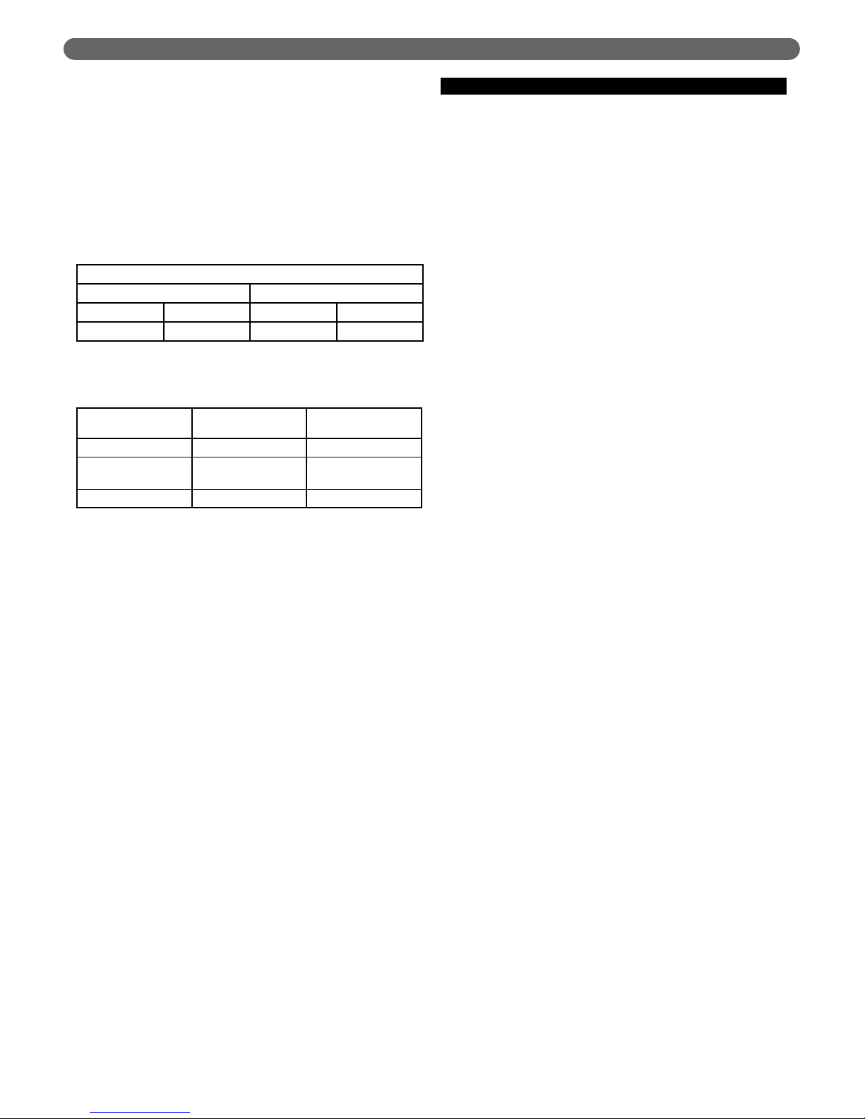
Figure 4.2: PureFire Circulator Sizing Graph
Do not operate this appliance without installing the
pressure relief valve supplied with the boiler or one
with sufficient relieving capacity in accordance with
the ASME Rating Plate on the boiler heat exchanger.
WARNING
70
65
60
55
PFW-200
50
45
40
35
30
Pressure Drop (Ft. of Water)
25
20
PFW-399
15
10
5
0
0 5 10 15 20 25 30 35 40 45 50 55 60 65 70 75 80
Flow Rate (GPM)
Page 19
17
WATER PIPING AND CONTROLS
c. The boiler pressure drop for various flow rates can
be determined using Figure 4.2, the PureFire
Boiler Pump Sizing Graph.
d. Table 4.4 provides the flow rate and pressure drop
information that corresponds to 20°F temperature
rise (ΔT). The pressure drop shown is for the
boiler only. If there is significant system pressure
drop in the circulation system between the boiler
and the tank, this should be included when
specifying pumps.
e. Table 4.5 provides a list of recommended pumps
for PureFire hot water supply boilers.
7. Flow Switch: The flow switch supplied with the boiler
is to be mounted as shown in figure 4.1 using the
fittings supplied with a minimum straight length of 5
pipe diameters before and after the switch.
D. SYSTEM PIPING
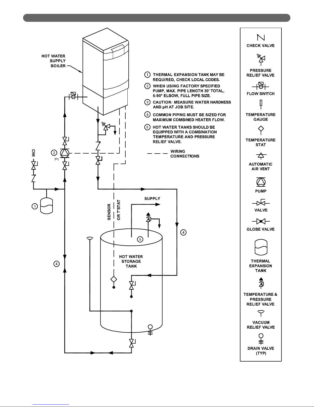
1. Figure 4.3 shows piping for a single boiler with a
single storage tank. When using the factory specified
pump, the maximum total pipe length is 30 feet (10
meters) with 6 90° elbows all at the full pipe diameter
of the pump connections.
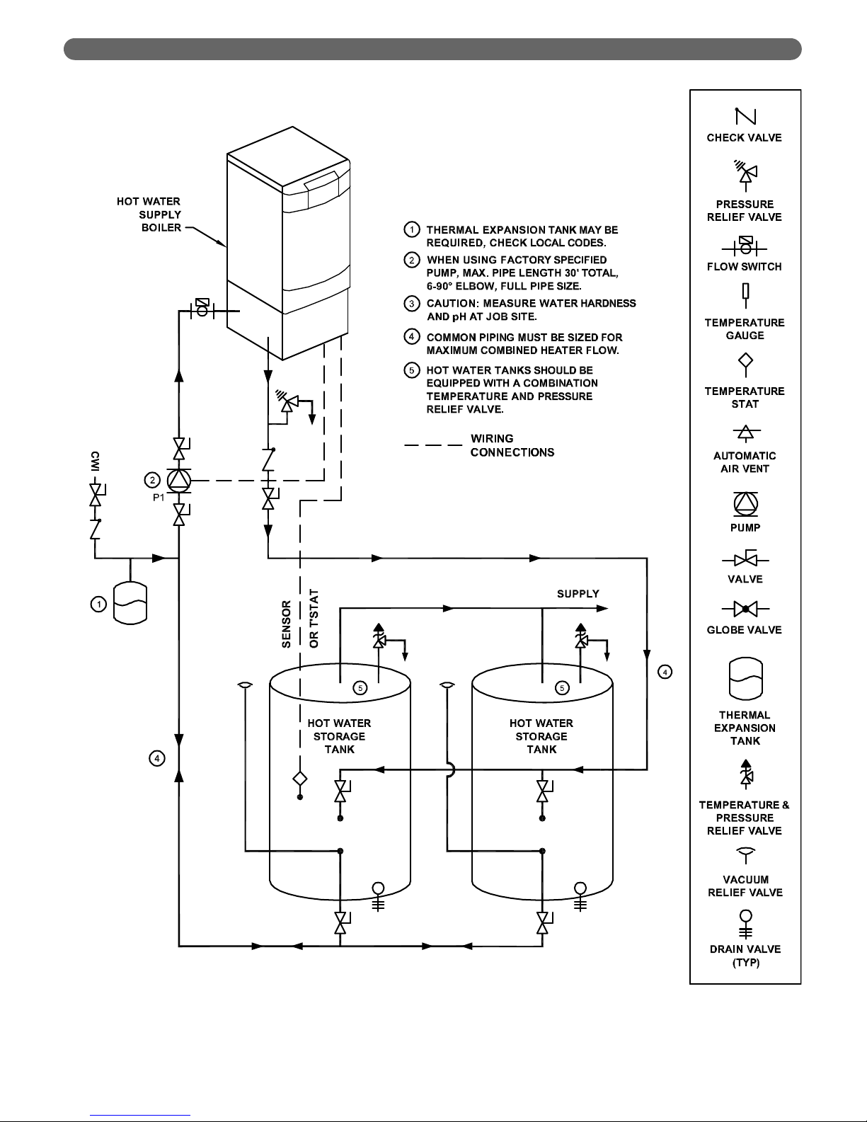
2. In Figure 4.4, a single boiler is used with multiple
water storage tanks. The pumps are piped in parallel
with reverse return piping.
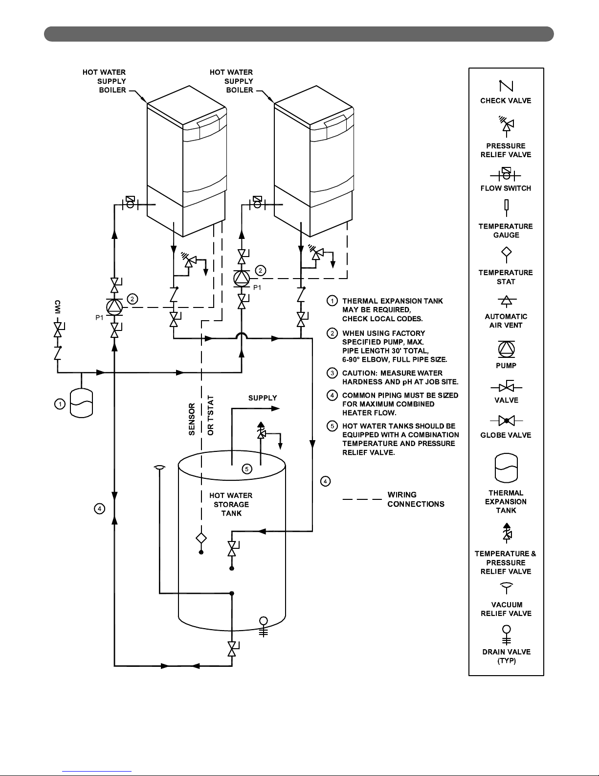
3. Figure 4.5 shows two boilers piped into a single
storage tank.
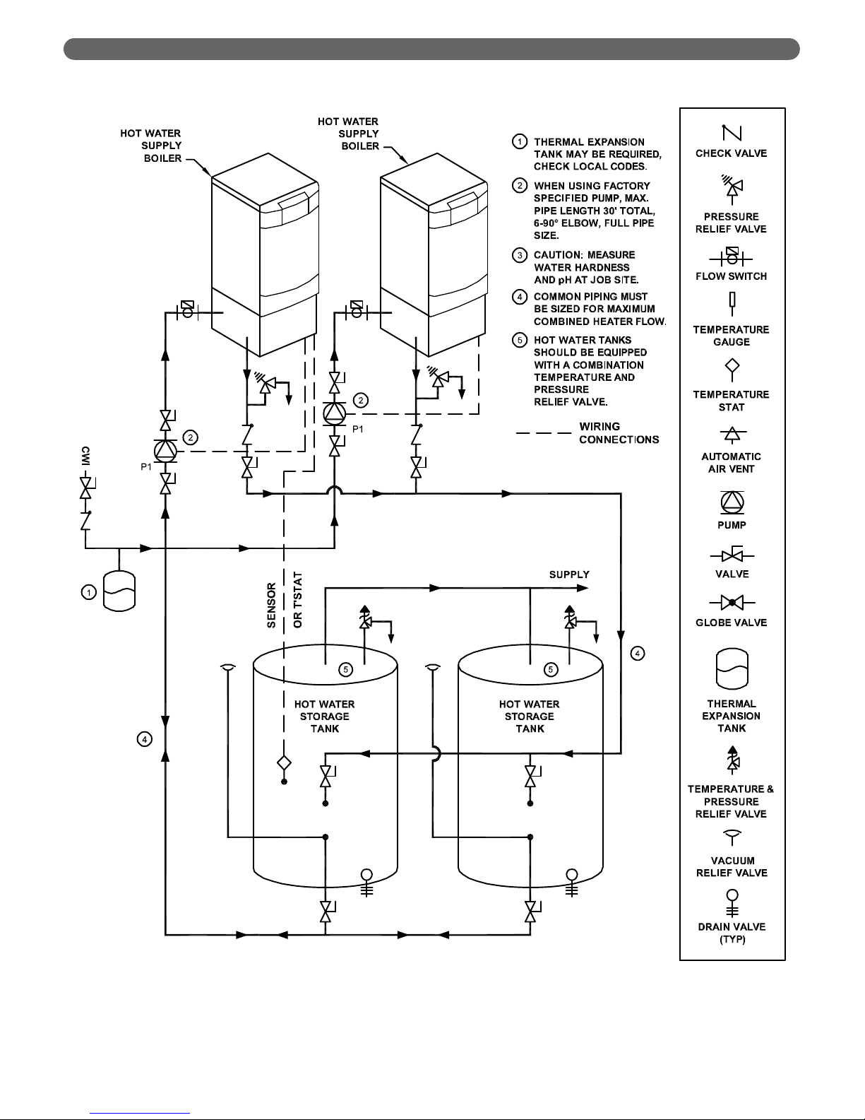
4. Figure 4.6 shows piping for two boilers and two water
storage tanks.
5. In Figure 4.7, we show a single boiler with a single
tank using a patented anti-scale principle. In this
configuration, the boiler control switches the 3-way
valve to bypass when the call for heat ends. The
pump is then operated to draw cool water from the
anti-scale buffer tank until the supply and return
temperatures equalize.
6. In Figure 4.8, a plate heat exchanger is used to isolate
the boiler from the domestic hot water supply system.
This strategy can be used if the domestic water does
not meet the water quality guidelines presented earlier
in this section. Note that a hydronic thermal
expansion tank is required in this closed-loop system.
Table 4.5: Pump Selection Chart (20°F ΔT)
Pump
Manufacturer
PFW-200 PFW-399
Bell & Gossett PL-36 PL-55
Grundfos
UPS32-80F
Medium Speed
UPS32-160F
Medium Speed
Taco 1400-20 1400-50
Table 4.4: Flow Rate and Pressure Drop for Various
System Temperature Rise Values
Flow Rate vs Pressure Drop at 20°F
PFW-200 PFW-399
GPM (LPM) Feet (m) GPM (LPM) Feet (m)
18.3 (69.3)
17.3 (5.3)
37.3 (141.2) 18.1 (5.5)
* Pumps must be bronze fitted for potable water application
Page 20
18
WATER PIPING AND CONTROLS
Figure 4.3: Schematic Piping - One Boiler with a Single Storage Tank
Page 21
19
WATER PIPING AND CONTROLS
Figure 4.4: Schematic Piping - One Boiler with Multiple Storage Tanks
Page 22
20
Figure 4.5: Schematic Piping - Two Boilers with a Single Storage Tank
WATER PIPING AND CONTROLS
Page 23
21
WATER PIPING AND CONTROLS
Figure 4.6: Schematic Piping - Two Boilers with Multiple Storage Tanks
Page 24

22
WATER PIPING AND CONTROLS
Figure 4.7: Schematic Piping - Alternate Piping with Patented Anti-Scale System
Page 25

23
WATER PIPING AND CONTROLS
Figure 4.8: Schematic Piping - One Boiler with a Single Storage Tank & Plate Heat Exchanger
Page 26

24
FUEL PIPING
A. GENERAL
1. All fuel piping to the PureFire boiler is to be in
accordance with local codes. In the absence of local
regulations refer to the National Fuel Gas Code, ANSI
Z223.1/NFPA 54.
2. Size and install fuel piping to provide a supply of gas
sufficient to meet the maximum demand of all
appliances supplied by the piping.
B. FUEL LINE SIZING
1. The required flow rate of gas fuel to the boiler can be
determined by the following.
The gas heating value can be supplied by the gas supplier.
2. As an alternative, use Table 5.1 to determine the
required gas flow rate which uses typical heating values
for natural gas and liquefied petroleum (LP) gas.
3. Table 5.2 shows the maximum flow capacity of
several pipe sizes based on 0.3" of pressure drop.
a. The values shown are based on a gas specific
gravity of 0.60 (Typical for natural gas).
b. Multiply the capacities listed by the correction
factors listed for gas with a specific gravity other
than 0.60 to obtain the corrected capacity.
4. Size and install the fuel gas supply piping for no more
than 0.5 inches of water pressure drop between the
gas regulator and the boiler.
C. GAS SUPPLY PIPING - INSTALLATION
1. Do not install any piping directly in front of the boiler
or along either side. Always provide access to the
front cover and side panel openings.
2. Install a sediment trap as shown in Figure 5.1. Be sure
to allow clearance from the floor or other horizontal
surface for removal of the pipe cap.
3. Install a ground joint union between the sediment trap
and the boiler to allow service to the appliance.
4. Install a service valve as shown in Figure 5.1 to allow
the gas supply to be interrupted for service.
5. Maintain a minimum distance of 10 feet (3048 mm)
between the gas pressure regulator and the boiler.
5. FUEL PIPING
Use a pipe joint sealing compound that is resistant to
liquefied petroleum gas. A non-resistant compound
may lose sealing ability in the presence of this gas,
resulting in a gas leak. Gas leaks may potentially
cause an explosion or fire.
WARNING
Pipe
Length
ft (m)
1/2" NPT
Pipe
3/4" NPT
Pipe
1" NPT
Pipe
1-1/4"
NPT
Pipe
1-1/2"
NPT
Pipe
10
(3.0)
132
(3.7)
278
(7.9)
520
(14.7)
1,050
(29.7)
1,600
(45.3)
20
(6.1)
92
(2.6)
190
(5.4)
350
(9.9)
730
(20.7)
1,100
(31.1)
30
(9.1)
73
(2.1)
152
(4.3)
285
(8.1)
590
(16.7)
890
(25.2)
40
(12.2)
63
(1.8)
130
(3.7)
245
(6.9)
500
(14.2)
760
(21.5)
50
(15.2)
56
(1.6)
115
(3.3)
215
(6.1)
440
(12.5)
670
(19.0)
60
(18.3)
50
(1.4)
105
(3.0)
195
(5.5)
400
(11.3)
610
(17.3)
70
(21.3)
46
(1.3)
96
(2.7)
180
(5.1)
370
(10.5)
560
(15.9)
80
(24.4)
43
(1.2)
90
(2.5)
170
(4.8)
350
(9.9)
530
(15.0)
90
(27.4)
40
(1.1)
84
(2.4)
160
(4.5)
320
(9.1)
490
(13.9)
100
(30.5)
38
(1.1)
79
(2.2)
150
(4.2)
305
(8.6)
460
(13.0)
The values are based on a specific gravity of 0.60 (typical for
natural gas). See Table 4.3 for capacity correction factors for
gases with other specific gravities.
Specific Gravity 0.50 0.55 0.60 0.65 0.70 0.75
Correction Factor 1.10 1.04 1.00 0.96 0.93 0.90
Specific Gravity 0.80 0.85 0.90 1.00 1.10 1.20
Correction Factor 0.87 0.84 0.82 0.78 0.74 0.71
Specific Gravity 1.30 1.40 1.50 1.60 1.70 1.80
Correction Factor 0.68 0.66 0.63 0.61 0.59 0.58
Table 5.2: Pipe Capacity:
Maximum Capacity of pipe in cubic feet per hour (cubic meters
per hour) with a pressure drop of 0.3" of water (75 Pa).
Boiler Input Rate
Gas Heating Value
Input Rate
(
ft
³
/
hr
)
=
(
Btu
/
hr
)
(
Btu
/
ft
³
)
Table 5.1: Required Fuel Input
PureFire
Model
Required Input Rate*
Natural Gas
ft3/hr (m3/hr)
LP Gas
ft3/hr (m3/hr)
PFW-200 199 (5.6) 80 (2.3)
PFW-399 399 (11.3) 160 (4.5)
* Natural gas input rates are based on 1,000 Btu/ft3, LP input
rates are based on 2,500 Btu/ft
3
.
Page 27

25
6. Check all gas piping for leaks prior to placing the
boiler in operation. Use an approved gas detector,
non-corrosive leak detection fluid, or other leak
detection method. If leaks are found, turn off gas flow
and repair as necessary.
7. Figure 5.1 shows the gas shutoff valve for the boiler.
This valve is to be used in addition to the gas service
valve shown upstream of the sediment trap.
D. GAS SUPPLY PIPING - OPERATION
1. The gas line must be properly purged of air to allow
the boiler to operate properly. Failure to do so may
result in burner ignition problems.
2. Table 5.3 shows the maximum and minimum fuel gas
supply pressure to be measured at the gas valve inlet
pressure tap. This pressure tap is depicted in Figure 5.2.
a. Gas pressure below 3.5 inches of water may result
in burner ignition problems.
b. Gas pressure above 13.5 inches of water may
result in damage to the automatic gas valve.
3. To check the gas supply pressure to on the gas valve:
a. Turn off the power at the service switch.
b. Close the gas shutoff valve.
c. Using a flat screwdriver, turn the screw inside the inlet
tap fitting (see Figure 5.2) one turn counter clockwise.
d. Attach the tube from the manometer to the
pressure tap fitting.
e. Open the gas valve and start the boiler.
f. Read and record the gas pressure while the boiler
is firing.
g. Turn off the boiler and close the gas shutoff valve.
h. Remove the manometer tube from the pressure
tap fitting.
i. Turn the internal screw clockwise to close the valve.
j. Turn on the gas shutoff valve and boiler service
switch.
k. Fire the boiler and check for fuel gas odor around
the gas valve. If an odor is evident check to make
sure that the pressure tap fitting is closed.
4. All gas piping must be leak tested prior to placing the
boiler in operation.
a. If the leak test pressure requirement is higher than
13.5 inches of water column, the boiler must be
isolated from the gas supply piping system.
b. If the gas valve is exposed to pressure exceeding
13.5 inches of water column, the gas valve must
be replaced.
5. Install the boiler such that the gas ignition system
components are protected from water (dripping,
spraying, rain, etc.) during operation and service
(pump replacement, condensate collector and
neutralizer cleanout, control replacement etc.)
E. MAIN GAS VALVE - OPERATION
1. Figure 5.2 is an illustration of the gas valve/venturi
assembly for the PureFire boiler.
a. Adjustments should not be made to the gas valve
without instrumentation to measure carbon
dioxide (CO
2
) and carbon monoxide (CO)
emissions in the vent pipe.
Do not subject the gas valve to more that 1/2 psi (13.5"
W.C.) of pressure. Doing so may damage the gas valve.
CAUTION
Table 5.3: Maximum and Minimum Fuel Pressure
Figure 5.1: Gas Supply Pipe and Shut-off
FUEL PIPING
Figure 5.2: Gas Valve/Venturi
Fuel Type
Pressure Inches W.C. (Pa)
Minimum Maximum
Natural Gas 3.5 13.5
LP Gas 3.5 13.5
When checking for leaks, do not use matches,
candles, open flames or other methods that provide
an ignition source. This may ignite a gas leak
resulting in a fire or explosion.
WARNING
Page 28

26
b. Turning the throttle screw clockwise will decrease
the gas flow (decreasing CO
2
) and turning it
counterclockwise will increase the gas flow rate
(increasing CO
2
). Markings adjacent to the throttle
screw show + and – indicating this operation.
c. The recommended CO
2
settings are given in Table
5.4. In no case should the boiler be allowed to
operate with CO emissions above 150 ppm.
2. Refer to Section 3, Venting and Air Intake for
information on obtaining vent samples from this boiler.
FUEL PIPING
Table 5.4: Recommended Combustion Settings
Natural Gas LP Gas
Low Fire High Fire Low Fire High Fire
Carbon Dioxide (CO2)
8.8% to 10.0% 8.5% to 9.5% 9.8% to 11.0% 9.5% to 10.5%
Carbon Monoxide (CO) < 50 ppm < 100 ppm < 50 ppm < 100 ppm
Excess Oxygen (O2)
3.4% to 5.4% 4.2% to 6.0% 4.2% to 6.0% 4.9% to 6.5%
Excess Air 17.3% to 31.0% 22.4% to 35.8% 22.4% to 35.8% 27.3% to 40.1%
Page 29

27
A. GENERAL
1. The disposal of all condensate into public sewage
systems is to be in accordance with local codes and
regulations. In the absence of such codes, follow these
instructions.
2. Proper piping and removal of condensation from
combustion is critical to the operation of a condensing
appliance. Follow these instructions carefully to assure
that your boiler operates correctly.
3. Depending on several factors, the condensate from
gas fired condensing appliances may have a pH value
as low as 2.5 (similar to cola soft drinks). Some local
codes require the use of neutralization equipment to
treat acidic condensate.
B. CONDENSATE SYSTEM
The PureFire condensate system is designed to prevent
condensate from backing up into the heat exchanger, trap
the condensate to prevent combustion gases from
escaping and neutralize acidic condensate. Refer to Figure
6.1 for an illustration of the system components.
1. Condensate Drain Hoses: The PFW-200 and PFW
399 have a drain hose attached directly to the
combustion chamber and one connected to a
bulkhead connection on top of the boiler. In systems
with long exhaust vent runs, the exhaust vent should
be connected to the condensate system as shown in
figure 6.2. This connection will drain to the boiler’s
condensate trap and neutralization system.
2. Condensate Collector Container: The condensate
collector is the semi-transparent container in the base
of the boiler near the back. This container collects the
condensate and acts as part of the trap to prevent
combustion gases from escaping. The container is
fitted with a float switch that prevents the boiler from
operating if the condensate line is clogged.
3. Condensate Float Switch: This switch will prevent the
boiler from operating if the condensate outlet is
clogged before the level of condensate reaches the
heat exchanger.
6. CONDENSATE DRAIN PIPING
Figure 6.1: Condensate Trap System
Figure 6.2: Separate Vent Condensate Drain
Installation
CONDENSATE DRAIN PIPING
Page 30

28
4. Condensate Neutralizer Container: The condensate
neutralizer is an additional semi-transparent container
near the front of the boiler. Fill this container with the
condensate neutralizer provided. The neutralizer will
be consumed during normal operation and should be
checked periodically to determine if the addition of
neutralizer is required. Neutralizer is available in 1 lb
bags (#54159) from your PB Heat Distributor.
5. Bulkhead fitting: The bulkhead fitting allows the
condensate tubing to pass through the jacket without
providing a path for leakage from the jacket. A PVC
TEE is to be attached to the outlet of this fitting to
prevent siphoning of the trap.
6. Neutralizer: Condensate neutralizer is provided in a
package with the boiler to fill the condensate
neutralizer container (Item 4).
7. Neutralizer Cap: This cap provides access for adding
and inspecting the condensate neutralizer.
8. Condensate Drain Tube: This pre-formed tube
connects the condensate system to the bulkhead
fitting for attachment to an external drain.
C. CONDENSATE DRAIN PIPE MATERIAL
The condensate drain is to be piped using PVC,
polypropylene, or other material resistant to acidic
condensate. Do not use steel, brass or galvanized pipe for
this purpose. The acidic condensate will attack most
metals and corrode.
D. CONDENSATE DRAIN PIPE SIZING
The bulkhead fitting for condensate connection is for 3/4"
schedule 40 PVC Pipe. Be sure to use 3/4" or larger
tubing from the boiler to the drain.
E. CONDENSATE DRAIN PIPE INSTALLATION
1. Connect a 3/4" schedule 40 PVC Tee to the outlet of
the bulkhead fitting as shown in Figure 6.3. Pipe from
the bottom of the tee to a suitable drain.
2. Be sure that the piping slopes away from the boiler
with a pitch of 1/4" per foot of pipe.
3. If the boiler condensate drain is above the level of a
gravity drain, a condensate pump should be used.
Table 6.1 lists several available brands. Contact your
PB Heat Distributor for availability.
Brand Name Model Number
Little Giant VCMA-15UL
Beckett CB151LSUL
Hartell KT-15-1UL
Table 6.1: Recommended Condensate Pumps
Figure 6.3: Condensate Drain Piping
CONDENSATE DRAIN PIPING
Page 31

29
A. GENERAL
This appliance is to be wired in accordance with local
codes and regulations as defined by the Authority having
jurisdiction. In absence of such local codes, the PureFire
boiler is to be wired in accordance with the latest edition
of the National Electrical Code, ANSI/NFPA 70.
B. CUSTOMER CONNECTIONS
1. Electrical knockouts are provided on the top panel of
the boiler to connect supply wiring, pump wiring and
wiring to various instruments.
2. Electrical terminals are located behind the User
Interface and can be accessed by loosening the two
nuts shown in Figure 7.1.
a. Remove one of the nuts and leave the other fully
loosened in order to leave the display interface
panel connected to the appliance.
b. The terminals can be removed by gently pulling
them away from their wired blocks. This allows
the installer to easily attach wires to the connector
before plugging it into the block.
3. Figure 7.2 shows customer wiring connections for the
PFW-200 and PFW-399 boilers.
a. Terminals 1 & 2 on the left side of the control cabinet
are for low voltage connection to a switch that
enables boiler operation. This is to be switched off to
prevent boiler operation during service.
b. Terminals 5 & 6 on the left side of the control
cabinet are for connection to either a DHW Tank
Sensor provided (54157) or to a tank thermostat
depending on the operating mode of the system.
c. Terminals 9 & 10 are to be connected to the flow
switch provided and/or low voltage contacts of a
low water cutoff device (supplied by others).
d. Terminals 11 & 12 on the left side are for
connecting multiple boilers together using a
cascade link which is described in Section 8.
e. Terminals 17 & 18 on the right side are provided
for either a pump or 3-way valve if used. This
operation is described in Section 8.
f. Terminals 21 & 22 on the right are for connection
to the boiler circulating pump. A boiler circulator
is always to be connected to assure circulation
during burner operation.
g. Terminals 23 & 24 on the right are for the
incoming 120 volt power supply.
h. Terminals 25 & 26 on the right provide power for
a probe-type low water cutoff device. Be sure to
remove any jumper that connect the 120 vac
power to the device contacts so line voltage isn’t
applied to the low voltage terminals (9 & 10).
i. Terminals 27 through 30 all connect to the ground
bus for any line voltage ground connections.
j. Terminal 31 & 32 are connect dry alarm contact
connections for use with an alarm or phone dialer.
These terminals are active only if the optional
PFA-1 adapter is used.
4. Note that the service switch does not disconnect
power to the convenience outlet.
C. INTERNAL WIRING
Figure 7.3 shows the complete boiler wiring schematic for
the PureFire boiler. The following is a list of internal
wiring components.
1. User Interface: The user interface is attached to the
front of the electrical junction box and is accessible by
removing the tinted lens on the front of the boiler.
This interface allows users and installers to
communicate with the control.
2. Supply/Return Sensors: These thermistors located on
the left header provide supply (boiler outlet) and return
(boiler inlet) temperature information to the control.
7. ELECTRICAL CONNECTIONS
Figure 7.1: Electrical Terminal Access
ELECTRICAL CONNECTIONS
The maximum pump/3-way valve load is 10 amps. If
the load on terminals 17 & 18 or terminals 21 & 22 is
greater than 10 amps, install isolation relays.
CAUTION
DO NOT Apply line voltage power to terminals 9 & 10.
If a jumper is included in the low water cutoff device
to supply power to the contacts, it must be removed
before powering the boiler. Failure to do so may
cause damage to the boiler.
CAUTION
Page 32

30
Be sure to only use a 12 kΩ thermistor for this boiler.
3. Limit Switch: This component is located on the left
header and is differentiated from the sensors by a red
Molex
®
connector. This is a high temperature limit
switch that, when used in combination with the Argus
integrated primary control, is listed in accordance with
the UL353 standard for Limit Controls. It will prevent
the boiler from operating if the supply water
temperature reaches a temperature above 195°F
(91°C). Once tripped, the boiler requires a manual
reset at the boiler display interface. Be sure to only
use the PureFire limit switch for this boiler.
4. Flue Sensor: This thermistor provides flue
temperature information to the control. It is located in
the vent connection inside the appliance jacket.
5. Condensate Drain Float Switch: This switch is
mounted in the condensate collector below the heat
exchanger in the rear of the cabinet.
6. Service Switch: Service Switch: The service switch
interrupts the power to the controls to allow service to
be performed. It does not disconnect incoming power
and/or power to the convenience outlet.
7. Convenience Outlet: The convenience outlet is
provided for a condensate pump during operation. It
is not switched with the service switch to allow its use
during maintenance.
8. Flame Sensor: The flame sensor uses the principal of
flame rectification to sense the burner flame. This is
located on the right side of the heat exchanger front
plate. After ignition, the control also senses flame
through the ignition electrode.
9. Gas Valve: The gas valve is connected through a
special cord and connector. The connector is attached
to the valve with a screw.
10. Ignition Electrode: This electrode is located on the left
side of the heat exchanger front plate. A 10,000 volt
charge is initiated by the control to provide a spark for
lighting the burner. After the burner lights, and no
spark is present, the control uses this electrode as a
second source of flame detection.
11. Combustion Air Fan: The combustion air fan has two
connections. There is a 120 volt power connection (3wire) and a low voltage control connection (4-wire).
12. Relay Module: A relay module is provided that
isolates the pump terminals on the integrated primary
control. Current loads higher than the allowable 10
amps will require additional isolation relays.
Figure 7.2: Customer Connections for PFW-200 & PFW-399 Boilers
ELECTRICAL CONNECTIONS
The service switch does not disconnect power from
the convenience outlet.
WARNING
Page 33

31
Figure 7.3: Internal Wiring Schematic for PFW-200 & PFW-399 Boilers
ELECTRICAL CONNECTIONS
Page 34

A. IGNITION SEQUENCE
Figure 8.1 shows the ignition sequence for the PureFire
boiler control. Table 8.1 describes each step in the
sequence in detail. The boiler control provides dual
sensing of the flame to maximize the reliability. The
control senses the burner flame with both the flame
sensor and the ignition electrode.
32
BOILER CONTROL: INTERNAL WIRING & OPERATION
8. BOILER CONTROL: INTERNAL
WIRING & OPERATION
Figure 8.1: Ignition Cycle – Graphical Representation
Table 8.1: Ignition Sequence
Period Demand Status User Interface Display
Standby
No demand is present.
If the power is on to the boiler and there is no DHW demand, the user interface will display “Standby” and show the boiler supply
temperature in the lower right corner of the screen. The time, in 24 hour format, is shown in the upper right. When a demand is
present, the boiler begins the ignition cycle.
Pre Purge
A DHW demand must be present to initiate ignition.
Once initiated the boiler will light.
When a demand is present, the control starts the combustion air fan. The fan speed then increases to ignition speed and the user
interface displays “DOMESTIC HOT WATER” along with “Trial for ignition.” This screen is displayed until the burner is lit and
stable or until a fault occurs. Once the ignition sequence begins it will continue through ignition even if the demand has ended.
Igntion Cycle
Safety On/Off
Standby
Pre-Purge
Demand
Fan
Pump
Gas Valve
Ignitor
Flame Signal
Pre-Ignition
Ignition
Purge
Burner On
Post Purge 1
Post Purge 2
Pump Post
State
On
Off
High
Ignition
Low
Off
On
Off
On
Off
On
Off
On
Off
Maximum 24 hours
2 seconds
4 seconds
5 seconds
2 seconds
320 milliseconds
maximum
10 seconds
minimum
30 seconds
Depends on
boiler settings
Page 35

33
BOILER CONTROL: INTERNAL WIRING & OPERATION
Period Demand Status User Interface Display
Safety
On/Off
A DHW demand has no influence in the Safety On/Off period.
The Safety On/Off step will continue even if the demand has
ended.
This step very quickly opens and closes the gas valve relays and determines if the control is operating correctly.
Pre-Ignition
A demand has no influence in the Pre-Ignition period.
Once the internal check is complete, the control begins a Pre-Ignition sequence. The igniter is energized while the gas valve
remains off. If a flame is detected at the end of the pre-ignition period a lockout will occur.
Ignition
A demand has no influence in the Ignition period.
The following displays occur on ignition failure only.
The igniter remains energized for the first 4 seconds of the Ignition period. For the final 2 seconds of the Ignition period, the igniter is
turned off and the control checks for a flame signal through both the ignition electrode and the flame sensor. If no flame signal is
present at the end of the Ignition period, the control initiates a post-purge and then begins the ignition cycle again. If there are three
consecutive ignition failures, the control will post purge and lockout.
Burner On
A demand must be present for the control to stay in this
period.
Once the flame signal is established, the burner will run until the demand is satisfied, the setpoint is exceeded, or a blocking error
occurs. The maximum run period for the burner is 24 hours. If the boiler runs continuously for 24 hours, the control will override
the demand and turn off the burner. After this a restart will occur and the burner will continue to run.
Post Purge 1
After the Post Purge period begins, a demand will be ignored
until after this period.
The following screen is displayed when the demand has ended.
During post purge 1, the control monitors the flame signal to be sure that the flame has extinguished. If a flame is detected after
the maximum 10 second time period, a control lockout will occur.
Post Purge 2
During this period a demand has no effect on operation.
The following screen will be displayed if the supply temperature
exceeds the target setpoint.
During this period, the combustion air fan runs at high speed to purge combustion gases from the heat exchanger. The minimum
setting for the fan post purge is 30 seconds. This can be increased to 90 seconds at the installer level of access.
Pump Purge
No demand is present.
The operation of the pumps and the boiler depend on the heat demand status.
Table 8.1: Ignition Sequence (continued)
Page 36

34
B. USER MENU
To access the User Menu, simply press the Menu key on
the display interface. Figure 8.2 shows the menu that will
appear:
Use the
Þ
and Ýkeys to move the arrow pointer to the
desired menu option. Then press Select to choose it.
1. USER MENU – STATUS
a. Current Setpoint
:
If the water tank is equipped with the tank
temperature sensor supplied with the unit,
choosing “Status” will display the tank
temperature. If an independent thermostat is used,
the boiler supply temperature will be displayed.
These screens are shown in Figure 8.3 and 8.4:
b. Sensor Temperatures:
Pressing the Þkey advances to the next status
screen which shows the Supply, Return and Tank
temperature sensor readings (Figure 8.5). If there
is no tank sensor, the reading for DHW will show
“CALL” or “NO CALL”. Pressing the
Þ
key again
shows the System and Exhaust Vent temperature
readings (Figure 8.6).
c. Circulator Status:
Pressing the
Þ
key once more shows the status of
the General Circulator Output (Terminals 21 &
22) and the DHW Circulator Output (Terminals 17
& 18). The display will indicate if the circulators
are On or Off. See Figure 8.7.
2. USER MENU – SETTINGS
a. DHW Tank Setpoint & Offset
:
If the water tank is equipped with the tank
temperature sensor supplied with the unit,
choosing “Settings” from the user menu will
display the screens shown in Figure 8.8 & 8.9.
The “Offset” value is added to the “Tank
Setpoint” to provide a target setpoint for the boiler
supply (outlet) temperature, “Boiler SP”, when the
unit is firing. To change the value, press the
Select key and the value will begin flashing. Use
the
Þ
and Ýkeys to decrease or increase the
value and then press Select again to save the
value. Table 8.2 shows the minimum, default and
maximum value for each of these parameters.
b. DHW Boiler Setpoint
:
If the water tank is using an independent
thermostat to control the tank temperature, the
screen shown in Figure 8.10 is displayed:
These values can be changed by using the
Select,
Þ
and Ýkeys as described above. Table
8.3 shows the value range for this parameters.
Figure 8.2: User Menu
Figure 8.3: Setpoint Status Display – Tank
Figure 8.4: Setpoint Status Display – Supply
Figure 8.5: Sensor Temperature Display #1
Figure 8.6: Sensor Temperature Display #2
Figure 8.7: Circulator Status
Figure 8.8: DHW Supply Offset & Boiler Setpoint
Figure 8.9: DHW Tank Setpoint
Parameter Minimum Default Maximum
Tank Setpoint 50°F (10°C) 140°F (60°C) 195°F (90°C)
Offset 0°F (0°C) 18°F (10°C) 36°F (20°C)
Table 8.2: Tank Setpoint & Offset Ranges
Note that the Boiler SP will not exceed 195°F (90°C) if the sum
of the Tank Setpoint and offset are above that value and the
boiler will not target the higher value.
Figure 8.10: DHW Supply Setpoint
Parameter Minimum Default Maximum
Boiler Setpoint 50°F (10°C) 180°F (82°C) 195°F (90°C)
Table 8.3: Boiler Supply Setpoint Range
BOILER CONTROL: INTERNAL WIRING & OPERATION
Page 37

c. Time & Date:
After setting the target setpoints, press the
Þ
key
to view the current time and date.
These values may be changed by pressing Select.
The day of the week will begin flashing. Use the
Þ
and Ýkeys to select the desired day of the
week, then press Select again. Now the “Date”
value will flash. Use the
Þ
and Ýkeys to choose
the date and press Select. Adjust the month,
year, hour and minute using the same procedure.
Pressing Select will save the values.
d. Temperature Units
:
Pressing the
Þ
key will display the Temperature
Units menu. See Figure 8.12.
Press Select to change the value and then use
the
Þ
and Ýkeys to toggle between “Fahrenheit
°F” and “Celsius °C”.
3. User Menu – Messages
a. Last Lock
:
Figure 8.13 shows the screen that displays the last
error requiring a manual reset of the control that
occurred with the control. Locking errors are in
the form of A## and are listed in Table 10.2 in
the Troubleshooting Section of this manual. A
value of 255 indicates that no locking errors have
occurred.
b. Last Block
:
Figure 8.14 represents the screen that shows the
last blocking error that occurred with this control.
Blocking errors are in the form of E## and are
listed in Table 10.1 in the Troubleshooting Section
of this manual. A value of 255 indicates that no
blocking errors have occurred.
C. INSTALLER MENU
To access the Installer Menu, press the Menu and Select
key on the display interface simultaneously and hold
them until the INSTALLER MENU is displayed. Figure
8.15 shows the menu:
Use the
Þ
and Ýkeys to move the arrow pointer to the
desired menu option. Then press Select to choose it.
1. Installer Menu – Status
a. Current Setpoint
:
If the water tank is equipped with the tank
temperature sensor included with the boiler, the
current tank setpoint is displayed on this screen
(Figure 8.16). If the tank is equipped with an
independent thermostat, then the current boiler
supply setpoint is displayed (Figure 8.17).
b. Fan Speed
:
Press
Þ
key to advance to screen #2 (Figure
8.18) which shows the current fan speed in
revolutions per minute (RPM). In addition, this
screen displays the minimum fan speed (Low
Power) for the particular model. Pressing the
Þ
key advances to screen #3 (Figure 8.19) which
shows the ignition fan speed and the maximum
fan speed (Hi Power) for the unit. The ignition
speed is the fan speed that the control targets
when the burner ignites.
Figure 8.11: Time & Date Settings
Figure 8.12: Temperature Units
Figure 8.13: Messages – Last Locking Error
Figure 8.14: Messages – Last Blocking Error
Figure 8.15: Installer Menu
r
r
y
g
f
Figure 8.16: Current Tank Setpoint – Tank Sensor
Figure 8.17: Current Boiler Supply Setpoint –
Supply Sensor
Figure 8.18: Fan Speed (Current & Low Power)
ST
A
2SUT▲
Fan Speed
Cu
r
r
en t 0RPM
Low Powe
r
1350RPM
▼
35
BOILER CONTROL: INTERNAL WIRING & OPERATION
INSTALLER MENU
Status
Bo i l e
Se
S
vice Notif.
stem Test
Se t t i ngs
Cascade Set t i n
De
au l t
s
Page 38

36
c. Flame Signal/Failures:
Pressing the
Þ
key advances the display to screen
#4 shown in Figure 8.20. This shows the current
flame signal as well as the any flame failures which
may have occurred since the boiler was installed.
Since the boiler control has a short lag time
between receiving the flame signal and displaying
it, a flame signal log records the flame signal at
half second intervals during the last 2 seconds of
the ignition period. Press the
Þ
key to advance
through status screen #5 & #6. Screen #5 (Figure
8.21) shows the readings at 1.5 seconds (Meas. 1)
and 1.0 seconds (Meas. 2) before the end of the
ignition sequence. Screen #6 (Figure 8.22)
displays the readings 0.5 seconds (Meas. 3) and at
the end of the ignition sequence (Meas. 4). This
may be helpful to determine the cause of an
ignition failure.
d. Ignition Attempts
:
Pressing the
Þ
key again advances the display to
screen #7 as shown in Figure 8.23. This screen
logs successful and failed ignition attempts. The
total of these two numbers is the number of
ignition attempts by the control.
e. Boiler Run Time
:
Once again, pressing the
Þ
key advances to the
next status screen. Screen #8 (Figure 8.24)
displays the total run time of the control which
includes the total of all time that the control is
powered but not in Standby.
f. Blocking Errors
:
Blocking errors prevent the boiler from operating
until the condition causing the error is corrected.
When the error is corrected, the boiler will
continue to operate. Screen #9 shows the last
blocking error to occur along with the relative time
of the error (Figure 8.25). The error number in the
format E## corresponds to the English language
description at the bottom of the screen. A complete
list of Blocking Errors is provided in Table 10.1 in
the Troubleshooting section of this manual.
Pressing the Select key displays the same error,
as shown in Figure 8.26, but now shows the time
between this error and the previous error in its
history. In this case, the “0” in the upper right
corner is flashing to indicate that this was the last
error to occur.
Pressing the
Ý
key while the “0” is flashing will
show the previous error in the control history and
the number “1” will flash in the upper right. See
Figure 8.27.
The Ýkey can be used to look at all 15 of the
blocking errors in the control history. When error
#255 is displayed (Figure 8.28), this indicates that
no errors occurred and the remainder of the errors
displayed will show this message.
Figure 8.19: Fan Speed (Ignition & High Power)
ST
A
3SUT▲
Fan Speed
I
g
ni t i on 4650RPM
Hi Powe
r
5940RPM
▼
Figure 8.20: Flame Signal & Flame Failures
ST
A
4SUT▲
Flame
Si
g
na l 9 . 6u
A
Fa i l ures 0
▼
Figure 8.21: Flame Signal Log – Last Ignition
#1 & #2
BO I L ER SE T T I NGS 5▲
V
en t Mat erial:
P
V
C
▼
Figure 8.22: Flame Signal Log – Last Ignition
#3 & #4
ST
A
6SUT▲
Flame
Meas . 3 6. 2u
A
Meas . 4 6. 5u
A
▼
Figure 8.23: Ignition Attempts
ST
A
7SUT▲
I
g
ni t ion
A
ttempts
Success
f
ul 1200
1deliaF
▼
Figure 8.24: Boiler Run Time
ST
A
8SUT▲
Bo i l e
r
Run T i me
700HR
▼
Figure 8.25: Blocking Error Status Screen
Figure 8.26: Blocking Error – History Screen 0
Figure 8.27: Blocking Error – History Screen 1
BOILER CONTROL: INTERNAL WIRING & OPERATION
Page 39

37
g. Locking Errors:
Locking errors indicate a condition which requires
someone to press the Reset key on the display to
allow the boiler to resume operation. These errors
are maintained in nonvolatile memory so that a
power cycle will not clear the error. Screen #10
(Figure 8.29) shows the last locking error and the
relative time it occurred.
The error number in the A## format corresponds
to the English Language description at the bottom
of the screen. A complete list of locking errors is
provided in Table 10.2 in the Troubleshooting
section of this manual. Pressing the Select key
displays the same error but now shows the time
between this error and the previous error in its
history. See Figure 8.30. In this case, the “0” in
the upper right corner is flashing to indicate that
this was the last error to occur.
Pressing the Ýkey while the “0” is flashing advance
to the previous error in the control history and the
number “1” will flash in the upper right as shown in
Figure 8.31. The
Ý
key can be used to look at all
15 of the blocking errors in the control history.
When error #255 is displayed (Figure 8.32), this
indicates that no errors occurred and the
remainder of the errors displayed will show this
message. Pressing the Menu/Return exits the
control history screen.
2. Installer Menu – Boiler Settings
a. DHW Mode
:
Choosing “Boiler Settings” from the Installer Menu
displays the DHW Mode screen depicted in Figure
8.33.
The DHW mode is used to choose between several
different configurations. Press the Select key
causes the mode number to flash. Use the Þand
Ý
keys to change the mode to the desired number.
Press the Select key again to save the new value.
Table 8.4 shows the available DHW Mode options:
Figure 8.28: Blocking Error – History Screen Error
#255
Figure 8.29: Locking Error Status Screen
Figure 8.30: Locking Error – History Screen 0
Figure 8.31: Locking Error – History Screen 1
Figure 8.32: Locking Error – History Screen Error
#255
Figure 8.33: DHW Mode Screen
BO I L ER SE T T I NGS 1
DHW mod e MODE : 1
DHW S t o
r
ewith
Senso
r
▼
BOILER CONTROL: INTERNAL WIRING & OPERATION
Table 8.4: DHW Modes
DHW Mode Description
1
Storage Tank with Temperature Sensor - Default
Using the 12 kΩ thermistor supplied with the boiler, the control directly monitors the storage tank temperature and fires the
boiler to maintain the desired temperature. Store Warm Hold: By monitoring the tank temperature, the control can determine if
the temperature drop is due to a hot water demand or to standby losses. For standby losses, the boiler will only fire at the
minimum input for maximum system efficiency.
2
Storage Tank with Separate Thermostat
In this mode, the control targets a fixed boiler setpoint temperature responding to a contact closure which indicates a call for heat.
The “Store Warm Hold” function will not be functional
if the DHW tank mode is set to 2. This requires a
DHW tank sensor.
NOTICE
Be sure to use only the tank sensor provided. Other
sensors may not provide accurate tank temperatures
and may cause severe personal injury due to scalding.
WARNING
In DHW Mode 1, DHW Store with Sensor, the display
screen will blink continuously if the sensor is not
connected to terminals #5 & #6.
NOTICE
Page 40

38
b. DHW Pump Post Purge:
After the storage tank is satisfied and the
combustion blower post-purge stops, the control
will continue to run the DHW Circulator (Terminals
#21 & 22) until the difference between the supply
and return temperatures on the boiler are less than
TDiff from screen #3 (Figure 8.35). The time that
this circulator runs is limited by the value of Max
DHW Pump Postpurge Time selected on Screen
#2 (Figure 8.34).
Table 8.5 shows the range and default values for
both the Max DHW Postpurge Time and Min.
Supply/Return Temperature Difference (TDiff).
c. Installation Location & Vent Material
:
To determine the suitable maximum vent
temperature limit, the boiler control uses the
Installation Location and the Vent Material. Screen
#4, shown in Figure 8.36, allows selection of the
Installation Location. Screen #5, shown in Figure
8.37, allows selection of the Vent Material.
Table 8.6 shows the vent temperature limit based
on vent material and installation location (due to
National Codes).
If the vent temperature approaches the vent
temperature limit, the control will reduce the input
rate of the boiler. If the input rate is at its
minimum (1% of modulation) and the vent
temperature is still at or above the limit
temperature, the control will turn off the boiler. An
error code of E30, High Stack Temperature, will
be displayed.
The minimum signal that the control can read
from the vent temperature sensor is 50°F (10°C). If
the vent temperature falls below this, the boiler
will monitor the boiler supply and return
temperatures while it is firing. If the water supply
temperature is below 120°F (49°C) and the return
temperature is below 80°F (27°C) the boiler will
operate normally. If either of these temperatures
exceed the indicated value, the control will limit
the boiler input to minimum firing rate (1% of
modulation). This is done to prevent overheating
of the exhaust vent material.
d. Freeze Protection
:
This feature is intended to protect from freezing
temperatures in the boiler system. If the supply
temperature drops below the freeze protection
starting point, the DHW pump (Terminals #21 &
22) are activated. If the supply temperature drops
more than 9°F (5°C) below this temperature, the
control starts the burner and operates it at it
minimum input rate (1% of modulation). Figure
8.38 shows the screen used to adjust the Freeze
Protection temperature start. This is under the
Boiler Settings screen on the Installer Menu.
Table 8.7 shows the minimum, default and
maximum temperature values for this parameter.
Figure 8.34: Maximum Pump Post-purge Time
BO I L ER SE T T I NGS 2▲
Ma x DH
W
Pump
Pos t Pu
r
g
eTime
60sec
▼
Figure 8.35: Min. Supply/Return Temperature
Difference
BO I L ER SE T T I NGS 3▲
Supp l
y
Re t urn
TD i
f
f
4°F
▼
Figure 8.36: Installation Location Selection
BO I L ER SE T T I NGS 4▲
Instal lat ion
Loca t i on
U S
A
▼
Figure 8.37: Vent Material Selection
BO I L ER SE T T I NGS 5▲
V
en t Mat erial:
P
V
C
▼
Figure 8.38: Freeze Protection Starting
Temperature
BO I L ER SE T T I NGS 6▲
F
r
eeze Protect ion
sta
r
ts at : 50°F
▼
Parameter Minimum Default Maximum
Freeze Protection start at: 45°F (7°C) 50°F (10°C) 56°F (13°C)
Table 8.7: Freeze Protection Value Range
BOILER CONTROL: INTERNAL WIRING & OPERATION
Table 8.6: Vent Temperature Limit Parameters
Vent Material
Installation Location
USA (Default) Canada
PVC (Default) 190°F (80°C) 149°F (65°C)
CPVC 230°F (110°C) 190°F (80°C)
Polypropylene 230°F (80°C) 230°F (80°C)
Stainless Steel 250°F (80°C) 250°F (80°C)
Table 8.5: DHW Pump Purge Parameters
Parameter Minimum Default Maximum
Max DHW Pump
Postpurge Time
0 sec (pump
postpurge disabled)
60 seconds 255 seconds
Min. Supply/Return
Temp. Difference
0°F 4°F 18°F
Page 41

e. Additional Safety Functions:
• The installer can choose between a low water
cut-off (LWCO) or a flow switch to prevent
firing of the boiler without sufficient water in
the system. Figure 8.39 shows the selection
screen for Additional Safety Functions.
• The control is shipped with LowWaterCO as a
default setting and includes a factory supplied
jumper that allows the boiler to operate if this
safety device is not installed. Table 8.8 shows
the available options for this parameter.
• If the boiler is set to flow switch, the control
first checks to assure that the circuit is open
before turning on the pump. Once the pump is
on, the control requires the flow switch circuit
to be closed.
• The system can accept both a LWCO and flow
switch as long as they are wired in series so
that the circuit opens when there is no flow in
the boiler.
f. Blower Post Purge
:
The installing contractor can increase the blower
post-purge time from the 30 second minimum up
to 120 seconds in 1 second increments. Figure
8.40 shows the Blower Post-purge Setting screen.
Table 8.9 shows the range of values for the Blower
Post-purge time. Keep in mind that increasing the
blower post-purge time can adversely affect the
efficiency of the boiler.
3. Installer Menu - Service Notification
a. The boiler allows the service technician to set up
notifications for routine maintenance. When
enabled, the notification can be set up on Hours
of Operation, Cycles, or on a pre-determined
date. When the notification criteria are met, the
screen shown in Figure 8.41 is displayed with
“SERVICE” flashing.
b. To reset the hour or cycle counters, press the
Select key on Screen #1 under Service
Notification shown in Figure 8.42.
c. Screen #2, shown in Figure 8.43, is used to set
the notification criteria. Table 8.10 shows the
choices for this parameter:
d. To set the number of hours until notification, press
the Select key while viewing Screen #3, shown
in Figure 8.44, and press the
Þ
and Ýkeys to
change the number of hours in 100 hour
increments.
e. Similarly to set the number of cycles, press the
Select key while viewing Screen #4 shown in
Figure 8.45 and press the t and s keys to change
the number of cycles in 1000 cycle increments.
Figure 8.39: Additional Safety Functions Selection
BO I L ER SE T T I NGS 7▲
A
dd i t i ona l
Sa
f
et
y
Func t ions
Low
W
aterCO
▼
Parameter Default Alternate
Additional Safety Functions LowWaterCO Flow Switch
Table 8.8: Additional Safety Function Values
Figure 8.40: Blower Post-purge Setting
BO I L ER SE T T I NGS 8▲
Blowe
r
Pos t Pu
r
g
eTime
30sec
▼
Parameter Minimum Default Maximum
Blower Post-purge Time 30 seconds 30 seconds 120 seconds
Table 8.9: Blower Post Purge Time Value Range
Figure 8.41: Service Notification Status
Figure 8.42: Reset Notification Time or Cycles
Figure 8.43: Notification Criteria
Criteria Minimum Default Maximum
Off Notification Disabled (Default)
HRS 0 HRS 4000 HRS 8000 HRS
CYCLES 0 CYC 20,000 CYC 50,000 CYC
DATE Set Date, Month & Year
Table 8.10: Notification Criteria
Figure 8.44: Notification on Hours
Figure 8.45: Notification on Cycles
39
BOILER CONTROL: INTERNAL WIRING & OPERATION
Page 42

40
f. Finally, to set a fixed date:
• Press the Select key while viewing Screen #5,
shown in Figure 8.46, and press the t and s
keys to change the Date (0-31). Press the
Select key again to advance to the Month.
• Press the
Þ
and Ýkeys to change the Month
(JAN-DEC). Press the Select key again to
advance to the Year.
• Press the
Þ
and Ýkeys to change the Year.
Press the Select key again to save.
4. Installer Menu – System Test
a. To allow service technicians to run the system at a
fixed input rate for commissioning and
troubleshooting purposes, the boiler control is
equipped with a System Test function.
b. Use the
Þ
and Ýkeys to move the arrow pointer
to the desired menu option. Then press Select to
choose it.
c. Choosing “Low Power” will operate the boiler at
its minimum input rate. A “SYSTEM TEST”
message will blink at the top of the status screen
and the boiler will run at it minimum temperature
unless either the temperature of the tank or boiler
supply is at or above the setpoint. In this case, the
control will not fire until both temperatures are
below the setpoint.
d. When the boiler first starts, the modulation rate
indication display the ignition modulation rate
(approximately 70%) lower left of the screen.
Once the burner is lit, the input rate will drop to it
minimum and 1% will be displayed to indicate
minimum modulation rate. See Figure 8.48.
e. Similarly, choosing “Maximum Power” will operate
the boiler at its rated capacity. With this selected
the display will show 100% after ignition is
established.
5. Installer Menu – Default Settings
a. The boiler allows a service person to reset all of
the boiler settings to the default settings that were
set up at the factory. To reset the default values
choose “Default Values” from the Installer Menu.
Figure 8.49 shows the Factory Defaults Reset
screen. Simply press the Select key to reset the
factory default values.
b. The control also allows the service technician to
Save and then Restore site default settings. The
screens depicted in Figure 8.50 and 8.51 show
these options.
6. Installer Menu – Cascade Settings (Multiple
Boilers)
a. The boiler allows system designs that include up
to 8 boilers cascading operation without the use of
external sequencing controls.
b. Figure 8.52 illustrates the wiring for
interconnecting cascaded boilers. No other wiring
is required between the boilers.
c. Managing Boiler Designation: To set up the
cascade system, one of the boilers is to be
designated the Managing boiler. This will be the
boiler that controls the system and will be
connected to the tank temperature sensor or tank
thermostat.
• First , switch the Master Switch Lever to the
“ON” position. The Master Switch Lever is in
the “ON” position when it is moved toward
the center of the printed circuit board as
shown in Figure 8.53.
• Next, from the installer menu, choose Cascade
Settings from the Installer Menu. Figure 8.54
shows the Address Selection screen that is
used to identify boilers in the cascade system.
Press the Select key and then use the
Ý
key
to change from “0” (indicating a stand-alone
boiler) to “1” (indicating the Managing Boiler).
Figure 8.46: Notification on Date
Figure 8.47: System Test Menu
Figure 8.48: System Test Status Display
Figure 8.49: Restore Factory Defaults
Figure 8.50: Save Site Defaults
Figure 8.51: Restore Site Defaults
BOILER CONTROL: INTERNAL WIRING & OPERATION
Page 43

d. Dependent Boiler Designation: Dependent boilers
must have different boiler addresses “2” to “8”.
Each dependent boiler must be connected to a
circulating pump. Table 8.11 shows address
selections for Stand-alone, Managing &
Dependent boilers.
e. Cascade Operation: When a call for hot water is
present, either from a thermostat or a by sensing
low tank temperature, the master boiler chooses a
lead boiler based on the Cascade Rotation Interval
(See Below).
• The control starts the lead boiler. After the
start delay time, each boiler in the cascade
system is started in succession.
The default value of this parameter is the
minimum to prevent a long delay before
starting another boiler. If the delay is
significant, it is possible that the tank
temperature will fall before all boilers are in
operation. If many boilers are installed and the
load is highly variable, consider using two
cascade systems. In this case, the tank sensors
for each system can be placed such that the
second group of boilers only comes on if there
is a very large load.
Figure 8.54: Cascade Address Selection
CASCADE
A
ddress Sel ect i on
Bo i l e
r
A
ddress : 0
▼
Parameter
Stand-alone
(Default)
Managing
Boiler
Dependent
Boilers
Boiler Address 0 1 2-8
Table 8.11: Boiler Address Selection Range
Figure 8.55: Start Delay Time
C
A
SCADE ▲
Sta
r
tDelayTi me:
10sec
▼
Parameter Minimum Default Maximum
Start Delay Time 10 seconds 10 seconds
240 seconds
(4 minutes)
Table 8.12: Start Delay Time Range
41
BOILER CONTROL: INTERNAL WIRING & OPERATION
Figure 8.52: Interconnection of Cascade Link Wires
Figure 8.53: Switching the Master Switch to the
“ON” position
Page 44

42
• With all the boilers operating, the system will
modulate the gas input to each of the boilers
to follow the system load. The control uses the
Stop Delay Time and the Stop Boiler
Differential values to determine when to drop
a boiler from the sequence.
If the tank temperature exceeds the Tank
Setpoint + the Stop Boiler Differential for
longer than the Stop Delay Time, it will stop
one of the boilers.
• The control uses the Tank Setpoint + the
Offset Temperature as set in the User menu to
provide a Boiler Supply Setpoint. It will then
offset this setpoint up or down to meet the
tank temperature. The Calculated Setpoint
Max Offset Up (Figure 8.58) and Calculated
Setpoint Max Offset Down (Figure 8.59) are
used to limit this offset. Increasing either of
these parameters may cause the system to
react more quickly, but may result in frequent
cycling. It may be necessary to reduce the Max
Offset Up to prevent a lockout on boiler limit.
Table 8.13 shows the range of values for these
parameters.
• The control also uses the Next Boiler Stop
Rate to determine when to shed a boiler from
the cascade system. Figure 8.60 and Table
8.14 show the screen and the range of values.
• The Cascade Rotation Interval (Figure 8.61)
will change the frequency at which the control
will change the lead boiler in the system.
• Table 8.15 shows how the Rotation Interval
affects the boiler rotation sequence.
Figure 8.56: Cascade Stop Delay Time
C
A
SCADE ▲
Stop Dela
y
Time :
1min
▼
Figure 8.57: Cascade Stop Boiler Differential
Parameter Minimum Default Maximum
Stop Delay Time 1 minute 1 minute 15 minutes
Stop Boiler Differential 1°F 18°F 45°F
Table 8.12: Start Delay Time Range
Figure 8.58: Calculated Setpoint Max Offset Up
C
A
SCADE ▲
Ca l cu l a t ed Se t p o i n t
Ma x o
f
f
set up:
18°F
▼
Figure 8.59: Calculated Setpoint Max Offset Down
C
A
SCADE ▲
Ca l cu l a t ed Se t p o i n t
Ma x o
f
f
set dow n :
9°F
▼
Parameter Minimum Default Maximum
Calculated Setpoint
Max Offset Up
0°F 18°F 36°F
Calculated Setpoint
Max Offset Down
0°F 9°F 36°F
Table 8.13: Calculated Setpoint Max Offset
Up/Down
Figure 8.60: Next Boiler Stop Rate
C
A
SCADE ▲
Nex t Bo i l e
r
Stop
r
ate:
9%
▼
Parameter Minimum Default Maximum
Next Boiler Stop Rate 5% 9% 40%
Table 8.14: Next Boiler Stop Rate
Figure 8.61: Rotation Interval
C
A
SCADE ▲
Rotat ion Inte
r
val
5Da
y
s
▼
Days of
Operation
1 Day 3 Days 5 days
1 1-2-3-4 1-2-3-4 1-2-3-4
2 2-3-4-1 1-2-3-4 1-2-3-4
3 3-4-1-2 1-2-3-4 1-2-3-4
4 4-1-2-3 2-3-4-1 1-2-3-4
5 1-2-3-4 2-3-4-1 1-2-3-4
6 2-3-4-1 2-3-4-1 2-3-4-1
7 3-4-1-2 3-4-1-2 2-3-4-1
8 4-1-2-3 3-4-1-2 2-3-4-1
9 1-2-3-4 3-4-1-2 2-3-4-1
10 2-3-4-1 4-1-2-3 2-3-4-1
11 3-4-1-2 4-1-2-3 3-4-1-2
12 4-1-2-3 4-1-2-3 3-4-1-2
Table 8.15: Rotation Interval (4 Boilers)
BOILER CONTROL: INTERNAL WIRING & OPERATION
Page 45

43
A. GENERAL
1. Confirm that all water, gas and electricity are turned off.
2. Verify that the water piping, venting & air intake
piping, gas piping, electrical wiring and electrical
components are installed in accordance with the
manufacturer’s instructions. Be sure that the boiler is
installed in accordance with this manual and good
engineering practice.
3. Turn on electricity and gas to the boiler
B. CHECK WATER PIPING
1. Fill the boiler and system with water, making certain
to purge all air from the system. Open each vent in
the system until all air is released and water begins to
be discharged. Then close the vent.
2. The pressure reducing valve on the fill line will
typically allow the system to be pressurized to 12 PSI.
Consult manufacturers instructions for operation of
the valve and expansion tank.
3. Check joints and fittings throughout the system and
repair as required.
C. CHECK GAS PIPING
1. Turn on gas to the boiler using the shut-off valve
upstream of the sediment trap. Be sure that the gas
shut-off valve supplied with the boiler is in the closed
position.
2. Connect a manometer to the gas supply upstream of
the supplied manual gas valve.
3. Confirm that the gas supply pressure to the boiler is
between the minimum and maximum values as
indicated in Section 5.
4. If a supply pressure check is required, isolate the
boiler and gas valve before performing the pressure
test. If the supply pressure is too high or too low,
contact the fuel gas supplier.
5. Double check the fuel gas supply pressure after the
boiler is running to be sure that the pressure doesn’t
drop off significantly under operation.
D. CHECK OPERATION
1. Be sure that the circuit between terminals #1 & #2 is
open to disable boiler operation.
2. Turn on electricity to the boiler leaving the manual gas
valves closed. Check to see that LCD display is lit.
Figure 9.1 shows the status display.
3. Refer to Section 8, Boiler Control, to set up the
control for the desired operation.
4. Close terminal #1 & #2 either with a switch or jumper
to enable boiler operation. Before opening the gas
valves, allow the boiler to attempt ignition 3 times
before locking out on Ignition Failure (A01). Then turn
the manual gas valves on and push the Reset key.
5. Use the ignition sequence, Figure 8.1 to follow the
light off and shutdown sequences and to assist in
troubleshooting operation problems. If the boiler does
not function properly, consult Section 10,
Troubleshooting.
6. After starting the boiler, be certain that all controls are
working properly and that the combustion is properly
set up. Paragraphs 7 and 8 below provide instructions
on how check combustion.
7. Check that the boiler will shut down when the supply
water temperature reaches the control setpoint.
a. Note the boiler setpoint by accessing the User
Menu, Status Display. Press the Menu key on the
keypad. Choose Status by pressing the Select
key. Use the
Þ
and Ýkeys to scroll through
available parameters. Refer to Section 8.B for
information on User Menu options.
b. Use the System Test Mode in the Installer Menu to
choose High Input Power.
c. Monitor the boiler temperature on the temperature
gauge (supplied for field mounting) and on the
Status display.
d. The boiler should shut down at the boiler setpoint
plus 10°F (5°C). If it does not shut down, turn off
the boiler and contact your PB Heat representative.
8. Check combustion readings in the boiler vent pipe.
a. For PVC or CPVC exhaust vent pipe only: Drill
and tap a 1/8" NPT threaded hole in the boiler
vent pipe within 12" (305 mm) of the boiler vent
connection. (21/64" Drill and 1/8" NPT Pipe Tap
recommended) This is to be used as the
combustion test port for the combustion analyzer.
See Figure 9.2.
b. Polypropylene vent systems from Centrotherm or
Duravent should include a sample port fitting
connected to the exhaust outlet port of the boiler.
In this case, this fitting is to be used as the test
port for the combustion analyzer.
9. START-UP PROCEDURE
START-UP PROCEDURE
Figure 9.1: Status Display DHW Disabled
Page 46

44
c. Using a combustion analyzer with the capability to
read carbon dioxide (CO
2
) and carbon monoxide
(CO), place the probe into the combustion test
port. See Figure 9.3.
d. Manually set the boiler to Maximum power by
entering the System Test Mode. See Appendix C,
Installer Menu.
• Verify that the fan speed indicated is within 30
rpm of the maximum power fan speed in
Table 12.2.
• Verify that the CO and CO
2
emissions are
within the parameters specified in Table 5.4.
e. Manually set the boiler to Low Power by entering
the System Test Mode. See Appendix C, Installer
Menu.
• Verify that the fan speed indicated is within
100 rpm of the Low Power fan speed listed in
Table 12.2.
• Verify that the CO and CO
2
emissions are
within the parameters specified in Table 5.4.
f. If the values in either of these instances falls outside
the parameters listed in Table 5.4, turn off the
boiler and contact your PB Heat representative. For
best results, the value should be set for the middle
of the range (9% for Natural Gas and 10% for
LP Gas).
g. Be sure to set the System Test mode to Off so that
the boiler will modulate correctly in accordance
with the load.
h. After removing the analysis probe from the vent
pipe, insert a PVC or Stainless Steel pipe plug into
the test port. See Figure 9.4.
i. Record the combustion readings on the “Start-up
Combustion Record” in Appendix D. It is very
important to record all of the information
requested on the sheet for follow up and
troubleshooting.
Figure 9.3: Insert Analyzer Test Probe into Test Port
Figure 9.4: Insert Pipe Plug into Test Port
START-UP PROCEDURE
Figure 9.2: Drill and Tap Combustion Test Port
Page 47

E. LIGHTING & OPERATING PROCEDURES
45
Figure 9.4: Lighting & Operating Instructions
START-UP PROCEDURE
Page 48

46
A. BLOCKING ERRORS
1. When a Blocking Error occurs the controller will
display a message and an “E” error code on the
display module.
2. These error messages and several suggested corrective
actions are included in Table 10.1.
3. Certain Blocking Errors will, if uncorrected, become
Locking Errors as described is Paragraph B.
B. LOCKING ERRORS
1. When a Locking Error occurs the controller will
display a message and an “A” error code on the
display module.
2. These error messages and several suggested corrective
actions are included in Table 10.2.
3. Press the Reset key to clear the Locking Error and
resume operation. Be sure to observe the operation of
the unit to prevent a recurrence of the fault.
4. The boiler control will retry for ignition after one hour
of being in a lockout condition. This will prevent
lockout errors from resulting in “No Heat” calls if
there is an intermittent problem.
5. The control logs the flame signal four times during the
last 2 seconds of the ignition period. This is to aid in
troubleshooting ignition errors. A flame signal below 2
micro-amps at the end of this period will result in a
lockout. If the flame signal is low, remove the flame
sensor and igniter for inspection. Also, be sure that the
lead to the flame sensor is not grounded.
10. TROUBLESHOOTING
If overheating occurs or the gas supply fails to shut
off, do not turn off electrical power to the circulating
pump. This may aggravate the problem and increase
the likelihood of boiler damage. Instead, shut off the
gas supply to the boiler at the gas service valve.
CAUTION
DANGER
When servicing or replacing components that are in
direct contact with the boiler water, be certain that:
• There is no pressure in the boiler. (Pull the release
on the relief valve. Do not depend on the pressure
gauge reading).
• The boiler water is not hot.
• The electrical power is off.
When servicing or replacing any components of this
boiler be certain that:
• The gas is off.
• All electrical power is disconnected.
WARNING
Do not use this appliance if any part has been under
water. Improper or dangerous operation may result.
Contact a qualified service technician immediately to
inspect the boiler and to repair or replace any part of
the boiler which has been under water.
WARNING
Label all wires prior to disconnection when servicing
controls. Wiring errors may cause improper and
dangerous operation. Verify proper operation after
servicing.
CAUTION
The convenience outlet is powered even when the
service switch is off.
CAUTION
TROUBLESHOOTING
Page 49

47
Table 10.1: Control Board Blocking Error Codes (automatic reset):
“E”
CODE
Error Display
Internal
No.
Error Description Corrective Action
E01
SUPPLY SENSOR
NOT CONNECTED
51 Supply sensor not connected. Check harness and sensor.
E02
RETURN SENSOR
NOT CONNECTED
52 Return sensor not connected. Check harness and sensor.
E04
DHW SENSOR
NOT CONNECTED
55 DHW sensor not connected.
If DHW Mode is not intended to be set to Mode 1,
DHW Store with Sensor, then change it to the
appropriate Mode.
Check harness and sensor.
E05 STACK SENSOR OPEN 57 Flue gas sensor open. Check vent temperature, harness, sensor.
E11 SUPPLY SENSOR SHORT 59 Supply sensor shorted. Check harness and sensor.
E12 RETURN SENSOR SHORT 60 Return sensor shorted. Check harness and sensor.
E13 STACK SENSOR SHORT 65 Flue gas sensor shorted. Check harness and sensor.
E14 DHW SENSOR SHORT 63 DHW sensor shorted. Check harness and sensor.
E19
COMMUNICATION ERROR
E2PROM ERROR
0
Problems reading from or writing
to e2prom.
Contact PB Heat Representative.
E20 FALSE FLAME DETECTED 35 False Flame detected. Verify no flame in observation port. Check Sensor.
E21 HOT/NEUTRAL REVERSED 44
Phase and neutral of mains
supply are reversed.
Verify polarity of incoming wiring. Check boiler
ground and harness.
E22 POOR GROUND 43
No earth connected or internal
hardware error.
Check boiler ground and harness.
E23 NET FREQUENCY ERROR 45
Mains frequency differs more
than 2% from 60Hz.
Contact electrical provider and/or an electrician.
E24 POOR GROUND 46 Earth connection is not ok. Check boiler ground and harness.
E25 BLOCKED VENT 38 Blocked Vent Switch is Open
Check for blocked vent pipe or blocked heat
exchanger. Check switch and tubing to switch.
E26
BLOCKED CONDENSATE
DRAIN
41 Condensate drain blocked.
Check condensate tanks, hoses, condensate switch,
and harness.
E30 HIGH STACK TEMPERATURE 39
Flue gas sensor above max flue
setpoint + diff.
If flue pipe is hot, check flue temperature and
compare to values shown Table 8.6. Check for
proper gas input and combustion readings, check
for dirty heat exchanger.
If flue pipe is not hot, check flue sensor and
harness.
E31 LOW WATER 36 Water level is too low.
Check boiler water level, low water cut-off, harness.
If a LWCO is not used, a jumper should be placed
between terminals #9 and #10, LWCO Contact.
E32 HIGH RETURN TEMP 40
Return temperature is above
194°F (90°C).
Check for reversed supply and return piping or
pump installed backwards.
E42 INTERNAL HDWRE ERROR 47 Internal hardware error. Replace control.
E45 INTERNAL HDWRE ERROR 31 Internal hardware error. Replace control.
E46 INTERNAL HDWRE ERROR 32 Internal hardware error. Replace control.
E47 INTERNAL HDWRE ERROR 33 Internal hardware error. Replace control.
E48 INTERNAL HDWRE ERROR 34 Internal hardware error. Replace control.
E51
RESET BUTTON ERROR
PLEASE WAIT.
66
Reset button pressed more than
7 times within one minute.
Wait five minutes. If error does not clear, replace
control.
TROUBLESHOOTING
Page 50

48
Table 10.2: Control Board Locking Error Codes (manual reset):
“A”
CODE
Error Display
Internal
No.
Error Description Corrective Action
A01 IGNITION ERROR 1
Three consecutive unsuccessful
ignition attempts.
1. Watch the igniter through the observation window.
2. If no spark is present, check the spark electrode
for the proper 3/16" gap.
3. Remove any corrosion from the spark electrode
with abrasive.
4. If spark is present but no flame, check the gas
supply to the boiler. Check for high or low
pressure.
5. If there is a flame, check the flame signal ignition
log in the Installer Menu. If values for flame signal
are less than 3.1 µA, check wiring connections
and clean the harness connector at the control.
6. Determine if gas valve is opening by monitoring
gas pressure.
7. Check gas presure.
A02 FLAME FAILURE 24
Three consecutive flame failures
during one demand.
1. If boiler sparks, lights briefly and then goes out:
a. Disconnect the flame sensor cable and then
retry ignition.*
b. If the flame stays lit, allow the boiler to run for
several minutes and then reattach the cable.*
c. If the problem persists, remove the flame
sensor and inspect the burner through the
sensor opening. If metal fibers are protruding
from the burner, use a blunt probe to move the
fibers away from the sensor.
d. If the problem is still present, replace the flame
sensor.
2. If the unit locks out on flame failure during
normal operation:
a. Check gas pressure at the inlet to the gas valve
(See figure 5.2) while the boiler is operating.
b. Check the flame signal in the Installer Menu
under Status. This will also show the total
number of flame failures. If the flame signal
reads less than 2.8 µA, clean the sensor and
igniter. Be sure that the wiring harness is fully
seated at the control.
c. If the flame signal is consistently low, check the
signal with the sensor disconnected. If the
flame signal improves, replace the flame sensor.
A03 OVERHEAT LIMIT OPEN 18
High Temperature Limit Open
[Set Temperature: 195°F (90.5°C)]
1. Check pump operation.
2. Assure that there is adequate flow through the
boiler by checking the status menu and assuring
less than 40°F (4.4°C) temperature rise across
the boiler.
3. Check thermistor reading on the supply
thermistor. Replace it if necessary.
A04
INTERNAL ERROR GAS VALVE
RELAY
5 Gas Valve Relay Problems. Replace control
A05
INTERNAL ERROR SAFETY
RELAY
6 Safety Relay Problems. Replace Control
A09
INTERNAL SOFTWARE ERR
RAM ERROR
9 Internal Software Error. Replace Control
A09 INTERNAL SOFTWARE ERR 27 Internal Software Error. Replace Control
A09 INTERNAL SOFTWARE ERR 28 Internal Software Error. Replace Control
A09 INTERNAL SOFTWARE ERR 29 Internal Software Error. Replace Control
A09 INTERNAL SOFTWARE ERR 30 Internal Software Error. Replace Control
A10
COMMUNICATION ERROR
E2PROM ERROR
12
No Communication with
E2prom.
Replace Control
* The flame is sensed through both the sensor and the igniter.
TROUBLESHOOTING
Page 51

49
“A”
CODE
Error Display
Internal
No.
Error Description Corrective Action
A12
SOFTWARE OUT OF DATE
E2PROM OUT OF DATE
10
Contents of e2prom is not
up-to-date.
Replace Control
A13 INTERNAL ERROR 13 Internal Software Error Replace Control
A14 INTERNAL ERROR 14 Internal Software Error Replace Control
A15 INTERNAL ERROR 16 Internal Software Error Replace Control
A16 INTERNAL ERROR 22 Internal Software Error Replace Control
A18 INTERNAL ERROR 19 Internal Software Error Replace Control
A19
FALSE FLAME DETECTED
AFTER SHUTDOWN
20
Flame signal detected 10 sec.
after closing the gas valve.
1. Check flame sensor to be sure there is no short to
ground.
2. Check igniter to be sure there is not short to
ground.
3. This could also indicate that the gas valve doesn’t
close completely.
A20
FALSE FLAME DETECTED
BEFORE IGNITION
21
Flame signal detected before gas
valve opened.
4. Check flame sensor to be sure there is no short to
ground.
Check igniter to be sure there is not short to
ground.
A23 FLOW_SW_NOT_OPEN 25 CH flow switch not working.
1. Check for electrical continuity between wires
connected to terminals 9 & 10 from field supplied
flow switch.
2. If there is continuity when the pump is off, there is
a system piping or pump control
problem.
A24 FLOW_SW_NOT_CLOSED 26 CH flow switch not working.
1. Check for electrical continuity between wires
connected to terminals 9 & 10 from the field
supplied flow switch.
2. If there is no continuity, check to be sure the
pump is working.
3. If the pump is working correctly, check the
flow switch.
A33 FAN SPEED ERROR 8
Fan speed detected is more than
300 rpm different from targeted
value for more than 60 seconds.
1. Is the fan running at full speed?
• Check 4 wire control connection to blower
and control.
• Replace harness.
2. Is the fan running at a modulated speed?
• Check 4 wire control connection to blower
and control.
• Replace harness.
3. Is the fan not running?
• Check the 3 wire power connection to the
blower and control.
• Replace harness.
• Replace Blower.
A50
RETURN HIGHER THAN
SUPPLY
11
Boiler return water temperature
higher than supply for more than
5 ignition attempts.
1. Check system piping. Assure that the water is
entering the return connection and exiting the
supply connection.
2. Compare the supply thermistor reading to the
temperature gauge, if they don’t agree, replace the
supply thermistor.
Table 10.2 (cont’d): Control Board Locking Error Codes (manual reset):
TROUBLESHOOTING
Page 52

50
Table 10.3: Control Board Warning Error Codes
“W”
CODE
Error Display
Error
Description
Corrective Action
#W02
Blinking Screen – Press “Reset” key to view this message
DHW Sensor
Open
1) Be sure the DHW Tank Sensor (54157),
provided with the boiler, is connected to
terminals #5 & #6.
2) Remove the wires from terminals #5 and
#6 on the boiler and check the resistance
between them.
a. If the resistance is above 10 k Ω, check the
resistance at the sensor.
b. If the reading at the sensor is the same,
replace the sensor.
c. If the reading at the sensor is lower, replace
the wiring.
C. WARNING ERRORS
The PureFire boiler control will display a blinking
screen under several conditions. Several of these
conditions provide the error information directly on
the screen. Table 10.3 shows sensor errors and
corresponding corrective actions.
DHW Sensor Error:
a. If the boiler control is set to operate on DHW
Mode 1 (DHW Sensor), and there is no sensor
connected the boiler will not satisfy a DHW call
for heat.
b. The display will blink and the DHW temperature
will read 14°F (-10°C) if there is an open circuit at
the sensor terminals. Pressing the “Reset” key will
display the following error screen.
c. This will also occur if the wires are not properly
connected.
d. If there is a short at the DHW sensor terminals
and the DHW mode is set to Mode 1, the DHW
system will not operate. The display will blink to
indicate a warning error. Pressing the “Reset” key
will display the following error screen.
TROUBLESHOOTING
Page 53

A. GENERAL (WITH BOILER IN USE)
General boiler observation can be performed by the
owner. If any potential problems are found, a qualified
installer or service technician/agency must be notified.
1. Remove any combustible materials, gasoline and
other flammable liquids and substances that generate
flammable vapors from the area where the boiler is
contained.
2. Remove any corrosive chemicals that may be stored
near the boiler. Chlorine, ammonia or similar products
can be very aggressive in a combustion environment.
3. Observe general boiler conditions (unusual noises,
vibrations, etc.)
4. Observe operating temperature and pressure on the
combination gauge located in the supply piping on
the left side of the boiler. Boiler pressure should never
be higher than 5 psi below the rating shown on the
safety relief valve (25 psig maximum for a 30 psig
rating). Boiler temperature should never be higher
than 240°F (116°C).
5. Check for water leaks in boiler and system piping.
6. Smell around the appliance area for gas. If you smell
gas, follow the procedure listed in the Lighting
Operating Instructions to shut down appliance in
Section 9, Start-Up Procedure Part B.
51
MAINTENANCE
11. MAINTENANCE
WARNING
Product Safety Information
Refractory Ceramic Fiber Product
This appliance contains materials made from refractory ceramic fibers (RCF). Airborne RCF
fibers, when inhaled, have been classified by the International Agency for Research on
Cancer (IARC), as a possible carcinogen to humans. After the RCF materials have been
exposed to temperatures above 1800°F (982°C), they can change into crystalline silica, which
has been classified by the IARC as carcinogenic to humans. If particles become airborne
during service or repair, inhalation of these particles may be hazardous to your health.
Avoid Breathing Fiber Particulates and Dust
Suppliers of RCF recommend the following precautions be taken when handling these
materials:
Precautionary Measures:
Provide adequate ventilation.
Wear a NIOSH/MSHA approved respirator.
Wear long sleeved, loose fitting clothing and gloves to prevent skin contact.
Wear eye goggles.
Minimize airborne dust prior to handling and removal by water misting the material and
avoiding unnecessary disturbance of materials.
Wash work clothes separately from others. Rinse washer thoroughly after use.
Discard RCF materials by sealing in an airtight plastic bag.
First Aid Procedures:
Inhalation: If breathing difficulty or irritation occurs, move to a location with fresh clean air.
Seek immediate medical attention if symptoms persist.
Skin Contact: Wash affected area gently with a mild soap and warm water. Seek immediate
medical attention if irritation persists.
Eye Contact: Flush eyes with water for 15 minutes while holding eyelids apart. Do not rub
eyes. Seek immediate medical attention if irritation persists.
Ingestion: Drink 1 to 2 glasses of water. Do not induce vomiting. Seek immediate medical
attention.
Page 54

52
B. WEEKLY (WITH BOILER IN USE)
Flush float-type low-water cut-off (if used) to remove
sediment from the float bowl as stated in the
manufacturer’s instructions.
C. ANNUALLY (BEFORE START OF
HEATING SEASON)
1. Check boiler room floor drains for proper functioning.
2. Check function of the safety relief valve by
performing the following test:
a. Check valve piping to determine that it is
properly installed and supported.
b. Check boiler operating temperature and pressure.
c. Lift the try lever on the safety relief valve to the
full open position and hold it for at least five
seconds or until clean water is discharged.
d. Release the try lever and allow the valve to close.
If the valve leaks, operate the lever two or three
times to clear the valve seat of foreign matter. It
may take some time to determine if the valve has
shut completely.
e. If the valve continues to leak, it must be replaced
before the boiler is returned to operation.
f. Check that operating pressure and temperature
have returned to normal.
g. Check again to confirm that valve has closed
completely and is not leaking.
3. Test low-water cut-off (if used) as described by the
manufacturer.
4. Test limit as described in Section 9, Part D,
“Check Operation”.
5. Test function of ignition system safety shut-off features
as described in Section 9, Part D, “Check Operation”.
6. Remove the top/front jacket panel and inspect for
any foreign debris that may have entered through air
intake vent.
7. Remove burner plate for inspection of burner and
coils. Refer to paragraph 11.E.1 for removal
procedure.
8. With boiler in operation check that condensate is
dripping from condensate tubing. Check for any
restriction in condensate drain line.
D. CONDENSATE CLEANING
INSTRUCTIONS
1. Removal of Condensate Tanks.
a. Close manual gas shutoff valve on top of boiler
and turn off power to the boiler by placing the
boiler service switch to the off position.
b. Remove the front jacket panel.
c. Remove the wing nut securing the front tank and
disconnect the tank from the upper right drain
hose. (Some condensate may spill out of this port).
d. Remove the cap from the tank and position a
container in front of the boiler and tilt the tank to
drain condensate into the container.
e. Tank and lower hose may be by removed by
disconnecting the lower hose from the rear tank.
f. Clean tank and hose with water and inspect the rear
tank for sediment in the lower connection port. The
rear tank can be removed for cleaning if required by
removing the wing nut and disconnecting the two
float switch wire leads. NOTE: Special care must be
taken when removing the hoses from the top of the
rear tank. They must be held secure and do not pull
hoses downward and away from their upper
connections to the heat exchanger and vent adapter.
g. After cleaning, replace tanks and reconnect hoses
and wire leads to float switch. Fill the front tank
with water and check for any leaks at connections.
h. Replace the front jacket panel, open the manual
gas valve and place the boiler service switch to
the on position.
2. Before re-starting the boiler follow the steps below:
a. Reconnect the thermostat wires.
b. Open the manual gas shutoff valve and reset the
thermostats.
c. Observe the boiler function to make sure you see
a condensate flow.
d. If you do not observe a condensate flow, repeat
the above procedure.
3. If the problem is not corrected at this point, it is possible
that there is a material deposit problem. Follow the Coil
Cleaning Instructions (Subsection 9E) below to dissolve
deposits and clean the heat exchanger.
The following annual inspection must be performed
by a qualified service technician.
CAUTION
When servicing or replacing components, be absolutely
certain that the following conditions are met:
• Water, gas and electricity are off.
• The boiler is at room temperature.
• There is no pressure in the boiler.
DANGER
The convenience outlet is powered even when the
service switch is off.
CAUTION
MAINTENANCE
It is extremely important to make sure there is no
blockage in the exhaust vent. Failure to do so may
result in serious personal injury or death.
WARNING
Page 55

53
MAINTENANCE
E. COMBUSTION CHAMBER COIL
INSPECTION AND CLEANING
INSTRUCTIONS
Before beginning this procedure, you must have on
hand the following items:
– a nylon or brass brush (not steel)
– “Rydlyme” (recommended for best results)
(available online www.rydlyme.com) or “CLR”
(available at most hardware stores)
1. Shut the boiler down and access the heat exchanger
using the following steps:
a. Close the manual gas shutoff valve and wait for
the unit to be cool to the touch.
b. Disconnect the condensate piping from the outside
connections (not from inside the boiler jacket) so
the flow can be observed.
c. Disconnect compression nut on gas valve inlet
and disconnect the gas valve electrical connector.
d. Remove the six 10 mm nuts from the burner
plate assembly. Disconnect wire leads to the
spark igniter and flame sensor. Disconnect two
Molex plugs from blower motor.
e. Pull the entire burner plate towards you to access
the heat exchanger coils.
2. Using a spray bottle filled with the recommended
product “Rydlyme” or “CLR”, spray liberally on the
coils, making sure the solution penetrates and
funnels down through the condensate hose. If the
condensate hose is blocked, let the chemical
penetrate for at least 15 minutes or until it drains.
3. Use the nylon or brass brush (do not use steel) and
scrub coils to remove any buildup, then vacuum the
debris from the coils.
4. Spray coils with clear water, making sure to confine
the spray to the area being cleaned (try to avoid
wetting the back ceramic wall of the unit). Flush the
combustion chamber with fresh water. At this point,
the boiler should be ready to power back up.
5. Reinstall the burner plate assembly using the
following steps:
a. Inspect the inside of the heat exchanger for dirt
and debris.
b. Install the burner plate assembly and replace the
six 10 mm nuts.
c. Reconnect the wire leads to the spark igniter,
flame sensor and gas valve. (Be sure that the
spark igniter is connected to the lead with the
thick insulation.) Reconnect the two Molex
®
plugs on the blower motor.
d. Connect the compression nut on the gas valve
inlet and reattach the gas valve electrical
connector.
e. Reset thermostats. (IMPORTANT: BE SURE
THAT THE VENT CONNECTION IS NOT
BLOCKED.)
f. Turn the power to the boiler on. Observe the
display module to assure proper operation.
g. Initiate a call for heat** and observe the
condensate flow.
h. Reconnect the condensate piping to the drain
connection.
**NOTE: When firing the boiler the first
few times you may experience some
fluttering of the gas burner that may result
in a flame lockout. This is normal and will
require you to recycle the unit until this
clears up. This is caused by water still
present in the combustion chamber.
6. Inspect exhaust vent and air intake vents for proper
support and joint integrity. Repair as necessary. Refer
to Section 5, VENTING.
7. Inspect exhaust vent and air intake vent terminations
for obstructions or corrosion. Corrosion is an
indication of exhaust gas recirculation.
It is extremely important to check for leaks when
reconnecting the gas valve. Failure to do so may
result in severe personal injury, death or major
property damage.
WARNING
Leaks in the vent system will cause products of
combustion to enter structure (vent system operates
under positive pressure).
WARNING
Significant deposits may be caused by the
recirculation of flue gases, dirt in the combustion air,
or poor fuel quality. Review Section 3: Venting of this
manual for proper venting configuration.
NOTICE
Significant deposits on the heating surface may be
the result of exhaust gases recirculating into the
combustion air. If deposits are evident, review
section 3 of this manual to be sure the exhaust vent
is installed correctly.
NOTICE
Page 56

54
12. BOILER DIMENSIONS & RATINGS
Table 12.1: Boiler Dimensions
Table 12.2: Boiler Ratings
PUREFIRE SERIES BOILER RATINGS
Boiler
Model
Input
(MBH/kW)
Heating
Capacity
(MBH/kW)
Net
Rating
(MBH/kW)
AFUE
(%)
Min. Max.
PFW-200 42/12.3 199/58.3 182/53.3 158/46.3 93.3
Gross Output
(MBH/kW)
Net
Rating
(MBH/kW)
Thermal
Efficiency
(%)
PFW-399 80/23.4 399/116.9
373/09.3
324/95.0 93.4
BOILER DIMENSIONS & RATINGS
Figure 12.1: Dimensional Drawing
PUREFIRE SERIES DIMENSIONS
Boiler
Model
“A” “B” “C” “D” “E” “F” “G” “H” “J” “K” “L”
PFW-200
16-9/16"
(421 mm)
17-3/16"
(436 mm)
40-1/2"
(1029 mm)
1"
(25 mm)
3"
(76 mm)
3/4"
(19 mm)
1-3/4"
(44 mm)
4-1/2"
(114 mm)
3"
(76 mm)
6-1/2"
(165 mm)
3-9/16"
(90 mm)
PFW-399
27-15/16"
(710 mm)
1-1/2”
(38 mm)
4"
(102 mm)
2-3/4"
(70 mm)
5-1/4"
(133 mm)
3-1/2"
(89 mm)
5-3/4"
(146 mm)
7-1/16"
(179 mm)
Page 57

55
BOILER DIMENSIONS & RATINGS
Table 12.3: Combustion Air Fan Speeds
PUREFIRE SERIES COMBUSTION AIR FAN SPEEDS
Boiler
Model
Input Rate
(MBH/kW)
Fan Speed
Low Power Ignition High Power
PFW-200 199/58.3 1350 4650 5940
PFW-399 399/116.9 1710 5790 7740
Table 12.4: PureFire Main Control Specifications
PUREFIRE SERIES MAIN CONTROL SPECIFICATIONS
Power Supply
120 VAC Nominal (102-132 VAC)
60 Hertz Nominal (40-70 Hertz)
Fuse (5562) 5 Amp, 250 VAC
Blower Voltage 120 VAC
Gas Valve Voltage 120 VAC
Thermostat Contacts 24 VAC
DHW Contacts 5 VDC
Flame Current Limits
Minimum (running): 2.8 µA
Minimum (ignition): 3.1 µA
Maximum: 10 µA
Temperature Sensors
NTC Thermistors are 12 kΩ @ 77°F (25°C) – 5 VDC
Supply Sensor: 14°F (-10°C) to 244°F (118°C)
Return Sensor : 14°F (-10°C) to 244°F (118°C)
Flue Sensor: 50°F (10°C) to 280°F (138°C)
DHW Sensor: 14°F (-10°C) to 244°F (118°C)
Listing Standards
Europe: CE EN298
North America: ANSI Z21.20 / CSA C22.2
Table 12.5: PureFire Electrical Ratings
PUREFIRE SERIES COMBUSTION AIR FAN SPEEDS
Boiler
Model
Supply
Voltage
Nominal
Freq.
Blower
Gas Valve Pumps
Max Total
Service
Current
Voltage
(VAC)
Current
(amps)
Voltage
(VAC)
Current
(amps)
Voltage
(VAC)
Max.
Current
(amps)
PFW-200
120 VAC 60 Hz 120 2.58 120
0.09
120 20.00
22.67
PFW-399 0.21 22.79
Page 58

Repair parts are available from your local PB Heat, LLC distributor or from Parts To Your
Door at 1 (610) 916-5380 (www.partstoyourdoor.com).
Note: Remember to include the boiler model number and serial number when ordering parts.
13. REPAIR PARTS
Figure 13.1: General Repair Parts
REPA IR PART S
56
Page 59

57
REPA IR PART S
Table 13.1: General Repair Parts – PFW200 & PFW399
Description
Quantity
Stock Code
PFW-200 PFW-399
1 Jacket Front Panel with Ball Studs (Provide Wiring Diagram Form No. when Ordering) 1 1 54256
2 Smoked Control Lens 1 1 54167
3 Display Module - PFW Boilers 1 1 54650
4 Display Bracket Gasket 1 1 54153
5 Display Bracket 1 1 PF2007-1
6 #6-32 Keps Nut 2 2 51553
7 #6-32 x 1/2" Long Hex Head Screw 2 2 5449
8 Flexible Gas Line 3/4" 1 1 54262
9 Gas Line Gasket 1 1 54142
10 3/4" NPT Manual Gas Shutoff Valve 1 1 51805
11 #10 x 1/2" Hex Head Sheet Metal Screw 4 4 99992
12 Lower Front Jacket Panel 1 1 PF6051
13
Left Side Jacket Panel
1 PF6049
1 PF6054
Right Side Jacket Panel
1 PF6050
1 PF6055
14 Bulkhead Fitting 2 2 54140
15 Bulkhead Fitting Gasket 2 2 54134
16 Leveling Leg 4 4 5429
17
1" NPT Brass Coupling 2 5534
1 1/2" NPT Brass Coupling 2 5551
18
1" NPT x 14 Brass Nipple 2 5557
1 1/2" NPT x 14 Brass Nipple 2 5550
19
1" NPT Brass Elbow 1 5558
1 1/2" NPT Brass Elbow 1 5553
20
1" NPT Brass Tee 1 5537
1 1/2" NPT Brass Tee 1 5554
21
1" NPT x 3" Brass Nipple 2 5559
1 1/2" NPT x 3" Brass Nipple 2 5552
22
1" NPT x 3/4" NPT Brass Reducing Bushing 1 5539
1 1/2" NPT x 3/4" NPT Brass Reducing Bushing 1 5556
23 3/4" NPT Brass Drain Valve 1 1 50756
24 Convenience Outlet 1 1 54136
25 #8-32 Keps Nut 4 4 51573
26
Control Module - PFW-200 1 54648
Control Module - PFW-399 1 54287
27 Rocker Switch (20 A, 120 VAC) 1 1 5701
28 Pump Isolation Relay Module 1 1 54610
29
3" Exhaust Vent /Air Inlet Adapter - PFW-200 1 54293
4" Exhaust Vent / Air Inlet Adapter - PFW-399 1 54294
30
3" Exhaust Vent Adapter Gasket - PFW-200 54133
4" Exhaust Vent Adapter Gasket - PFW-399 54217
31 #10 x 3/4" Phillips Pan Head Type A Screw 6 6 5611
32
3" Heat Exchanger Outlet Collar - PFW-200 1 5531
4" Heat Exchanger Outlet Collar - PFW-399 1 5532
33 Condensate Neutralizer Assembly 1 1 54204
34 Condensate Receiver Assembly 1 1 54259
35 Blocked Vent Switch (includes items 36 & 37) 1 1 54260
36 3/16" ID PVC Tubing x 12 " Long 1 1 5563
37 90 Deg Barbed Elbow Adapter Fitting 1 1 5698
38 Thermal Fuse Cover Gasket 1 1 54141
39 Thermal Fuse Cover 1 1 PF2021
– Wiring Harness (includes Right Side Terminal Block, J2MN & J4/5RM Connectors) 1 1 54629
– Wiring Harness (J6 Outputs to Relay Module) 1 1 54627
– Wiring Harness (J7 Pump Output to Relay Module) 1 1 54628
– Wiring Harness (Supply/Limit Adapter) 1 1 54421
– Wiring Harness (Includes Left Side Terminal Block & J5/J16 Connectors) 1 1 PF7021
– Wiring Harness (Gas Valve/Flame Sensor Connectors) 1 1 PF7023
– Wiring Harness (Ground Wire) 1 1 PF7024
– 10 Pole Terminal Block Push-On Connector 1 1 5450
–
6 Pole Terminal Block Push-On Connector
1 1 5547
–
Ignition Cable
1 1 54115
– Relief Valve - 125 PSI 1 1 54274
–
12 kΩ Flue Sensor
1 1 54209
– Flue Sensor Grommet 1 1 54291
– High Limit Switch 1 1 54419
–
12 kΩ Supply/Return Sensor
1 1 54418
–
12 kΩ Tank Temperature Sensor
1 1 54157
Page 60

58
Figure 13.2: Heat Exchanger/Burner Assembly Repair Parts
REPA IR PART S
Page 61

59
REPA IR PART S
Table 13.2: Heat Exchanger/Burner Assembly Repair Parts
Description
Quantity
Stock Code
PFW-200 PFW-399
1 Ignitor with Gasket 1 1 54246
2 Sensor with Gasket 1 1 54247
3 M4 x 8 mm Screw 4 4
4 M5.5 x 14 mm Screw Fine Thread (0.5) 5 5
5
Premix Channel - PFW-200 1 54249
Premix Channel - PFW-399 1 54250
6 Burner Gasket 1 1 54186
7
Premix Burner Element - PFW-200 1 54263
Premix Burner Element - PFW-399 1 54264
8 M6 Nut (Fine Thread) 6 6
9 Combustion Chamber Cover Plate (includes #10 & #12) 1 1 54248
10 Fiberglass Rope Gasket 1 1 54188
11 Gasket Rubber 1 1 54187
12 Combustion Chamber Cover Plate Insulation 1 1 54255
13 M4 x 8 mm Stainless Steel Screw 1 1
14 M4 Stainless Steel Fender Washer 1 1
15 Target Wall Insulation 1 1 54185
16
Heat Exchanger - PFW-200 1 5529
Heat Exchanger - PFW-399 1 5530
17 Blower Outlet Gasket 1 1 54122
18
Combustion Air Blower - PFW-200 1 54258
Combustion Air Blower - PFW-399 1 54257
19 M5 x 12 mm Screw 4 4
20
Blower Adapter Plate - PFW-200 1 5421
Blower Adapter Plate - PFW-399 1 5610
21 M4 x 10 mm Screw 3 3
22
Swirl Plate - PFW-200 1 54251
Swirl Plate - PFW-399 1 54252
23
Gas Valve - PFW-200 (includes #22 & #24) 1 54253
Gas Valve - PFW-399 (includes #22 & #24) 1 54254
24
M4 x 25 mm Screw (PFW-200) 3
M4 x 30 mm Screw (PFW-399) 3
Page 62

60
REPA IR PART S
Table 13.3: Optional Exhaust Vent Termination Kits
Description
Quantity
Stock Code
PFW-200 PFW-399
–
3" Concentric Sidewall Termination Kit (PolyPro 3PPS-HK) • 54498
–
4" Concentric Sidewall Termination Kit (PolyPro 4PPS-HK) • 54499
–
3" Concentric Vertical Termination Kit (PolyPro 3PPS-VK) • 54500
–
4" Concentric Vertical Termination Kit (PolyPro 4PPS-VK) • 54501
Table 13.4: Optional Polypropylene Exhaust System Adapters
Description
Quantity
Stock Code
PFW-200 PFW-399
–
3" Polypropylene Vent/Inlet Adapter (Innoflue ISAGL0303) • 54632
–
4" Polypropylene Vent/Inlet Adapter (Innoflue ISAGL0404) • 54633
–
3" Polypropylene Vent/Inlet Adapter (PolyPro 3PPS-AD) • 54630
–
4" Polypropylene Vent/Inlet Adapter (PolyPro 4PPS-AD) • 54631
Figure 13.4: Concentric Vertical Vent Termination
Figure 13.3: Concentric Horizontal Vent
Termination
Figure 13.5: Polypropylene Adapter
Page 63

61
APPENDIX A. STATUS SCREENS
APPENDIX A. STATUS SCREENS
Page 64

62
APPENDIX A. STATUS SCREENS
Page 65

63
APPENDIX A. STATUS SCREENS
Page 66

64
APPENDIX B. USER MENU
APPENDIX B. USER MENU
Page 67

65
APPENDIX B. USER MENU
Page 68

66
APPENDIX C. INSTALLER MENU
APPENDIX C. INSTALLER MENU
Page 69

67
APPENDIX C. INSTALLER MENU
Page 70

68
APPENDIX C. INSTALLER MENU
Page 71

69
APPENDIX C. INSTALLER MENU
Page 72

70
APPENDIX C. INSTALLER MENU
Page 73

71
APPENDIX C. INSTALLER MENU
Page 74

72
APPENDIX D. COMBUSTION TEST RECORD
APPENDIX D. COMBUSTION TEST RECORD
Contact:
Company Name:
Address:
Phone Number:
Fax Number:
Email Address:
Jobsite Data
Job Name:
Jobsite Address:
Boiler Data
Boiler Model: Boiler Serial No.:
Manufacture Date: Startup Date:
Gas Pressure
Static Inlet Gas Pressure
(in. w.c.) [With Boiler Off]:
Inlet Gas Pressure
Drop After Boiler Startup
(in. w.c.):
High Fire Outlet Gas
Pressure (in. w.c.):
Low Fire Outlet Gas
Pressure (in. w.c.):
Combustion Readings
Flame Signal
High Fire (µA):
Flame Signal
Low Fire (µA):
CO²High Fire (%): CO²Low Fire (%):
CO High Fire (ppm): CO Low Fire (ppm):
Fan Speed High Fire: Fan Speed Low Fire:
Excess Air
High Fire (%):
Excess Air
Low Fire (%):
Exhaust Temperature
High Fire (°F):
Exhaust Temperature
Low Fire (°F):
System Information
Water Pressure: Condensate Line Size:
Vent Length
(Total Equivalent Feet):
Vent Diameter:
PureFire Combustion Test Record
Page 75

73
NOTES
Page 76

®
Hot Water
Supply Boilers
Gas
Installation,
Operation &
Maintenance
Manual
TO THE INSTALLER:
This manual is the property of the owner and must
be affixed near the boiler for future reference.
TO THE OWNER:
This boiler should be inspected annually by a
Qualified Service Agency.
PF8234 R0 (06/14-1M)
Printed in U.S.A.©2014 PB Heat, LLC. All rights reserved.
PB HEAT, LLC
131 S. CHURCH STREET • BALLY, PA 19503
PFW-200 PFW-399
PUREFIRE
®
PFW™SERIES
CONTROLS
 Loading...