

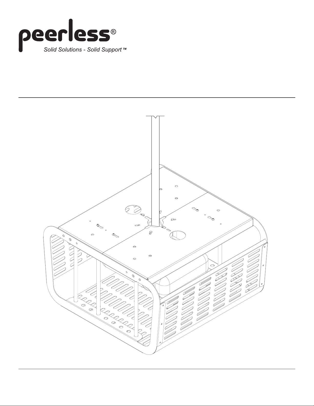
Installation and Assembly:
Projector Enclosure
Models: PE 1120, PE 1120-W
3215 W. North Ave. • Melrose Park, IL 60160 • (800) 729-0307 or (708) 865-8870 • Fax: (708) 865-2941 • www.peerlessmounts.com
ISSUED: 07-11-06 SHEET #: 055-9462-1

Note: Read entire instruction sheet before you start installation and assembly.
WARNING
• Do not begin to install your Peerless product until you have read and understood the instructions and warnings
contained in this Installation Sheet. If you have any questions regarding any of the instructions or warnings, please
call Peerless customer care at 1-800-729-0307.
• This product should only be installed by a qualified professional.
• Make sure that the supporting surface will safely support the combined load of the equipment and all attached hardware and components.
• Always use an assistant or mechanical lifting equipment to safely lift and position equipment.
• Tighten screws firmly, but do not overtighten. Overtightening can damage the items, greatly reducing their holding
power.
IMPORTANT! Turn to the appropriate page for your ceiling installation.
Applications:
Suspended Ceiling.......................................................................................................................................... page 4
Extension Column ........................................................................................................................................... page 5
Flush Mount ..................................................................................................................................................... page 6
Tools Needed for Assembly
• open-end 8 mm wrench
• open-end 1/2" wrench
For customer care call (800) 729-0307 or (708) 865-8870.
2 of 7
ISSUED: 07-11-06 SHEET #: 055-9462-1
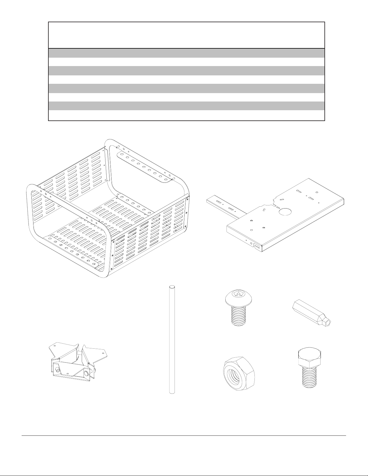
Parts List
Description Qty. Pa rt # Pa rt #
projector cage 1 055-1690 055-2690
A
top plate 2 055-0695 055-0697
B
pole clamp 1 055-0694 055-0696
C
.5" dia. X 12" rod 8 580-1163 580-2163
D
M5 x 10 mm penta pin screw 4 505-9010 500-2001
E
M5 x 1" penta pin driver 1 520-9249 520-9249
F
5/16-18 nylock nut 1 530-1009 530-1009
G
M5 x 10 mm hex screw 3 520-1324 520-2324
H
PE 1120 PE 1120-W
A
C
D
G
E
B
F
H
3 of 7
ISSUED: 07-11-06 SHEET #: 055-9462-1

Suspended Ceiling Application
WARNING
• Make sure that the supporting surface will safely support the combined load of the equipment and all attached hardware and components.
Note: If flush mount tube has been installed in suspended ceiling mount, remove it before proceeding with this step.
From the bottom up, thread extension column (EXT 006, not included) up through retaining collar in adjustable collar
1
mount plate. Align notch in extension column with hole in collar and fasten using M5 x 10 mm security screw as
shown in detail 1.
continue to extension column application on page 5 for attachment of projector enclosure...
CEILING MOUNT
FLUSH MOUNT TUBE
DETAIL 1
M5 X 10 MM
SCREW
4 of 7
ISSUED: 07-11-06 SHEET #: 055-9462-1

Extension Column Application
WARNING
• Make sure that the supporting surface will safely support the combined load of the equipment and all attached hardware and components.
Note: Refer to projector mount instruction sheet for attachment of projector mount to extension column.
Wrap pole clamp (C) around extension column (not
1
included) and secure with nylock nut (G). Hand
tighten all nylock nuts on pole clamp (C).
Note: Pole clamp (C) will work with 1" to 1-1/2"
NPT pipe.
EXTENSION
COLUMN
(NOT INCLUDED)
C
G
Slide top plates (B) together over pole clamp (C).
1-1
Slide M5 screws into keyhole slots and tighten as
shown in detail 1.
Note: If M5 screws are inaccessible from the top,
remove them from top plates and insert from the
bottom using bottom holes and keyhole slots.
C
B
BOTTOM HOLE
BOTTOM
KEYHOLE SLOT
M5 SCREW
KEYHOLE SLOT
DETAIL 1
Align slots in top plates (B) with holes in pole clamp (C) and insert three M5 x 10 mm hex screws (H). Tighten
1-2
screws using open-end 8 mm wrench (not provided).
Rotate top plates (B) and pole clamp (C) until top plates are parallel with projector. Then, tighten nylock nuts on pole
1-3
clamp using an open-end 1/2" wrench (not provided).
continue to step 2 on page 7...
H
B
C
5 of 7
ISSUED: 07-11-06 SHEET #: 055-9462-1

Flush Mount Application
WARNING
• Make sure that the supporting surface will safely support the combined load of the equipment and all attached hardware and components.
Remove M5 penta pin screws from top plates (B).
1
B
M5 PENTA PIN
SCREW
Attach top plates (B) to ceiling using outer holes
1-1
indicated in figure 1.1.
Note: It is the responsibility of the installer to
provide fasteners appropriate for the mounting
surface.
CEILING
B
fig 1.1
Note: Refer to projector mount instruction sheet for attachment of projector mount to ceiling.
Following projector mount instructions for flush mount applications, attach projector mount to ceiling through slots
1-2
indicated in figure 1.2.
CEILING
B
PROJECTOR
MOUNT
fig 1.2
6 of 7
ISSUED: 07-11-06 SHEET #: 055-9462-1

Slide rods (D) into holes of projector cage (A). Use
2
as many rods as necessary to prevent projector
from being removed from projector cage.
Note: Position rods where projector lens will not be
obstructed.
D
A
Insert pegs on one side of projector cage (A) into
3
slots of one top plate (B) and slide all the way to
last notch. Insert pegs on other side of projector
cage into slots of other top plate and slide over until
all pegs are resting on middle notches of slots.
A
B
PEG
Secure projector cage (A) to top plates (B) using
3-1
four M5 x 10 mm penta pin screws (E). Tighten
screws using penta pin driver (F).
Note: Padlock may be
used for added security.
E
B
SLOT
7 of 7
All other brand and product names are trademarks or registered trademarks of their respective owners.
ISSUED: 07-11-06 SHEET #: 055-9462-1
© 2006 Peerless Industries, Inc. All rights reserved.
Peerless is a registered trademark of Peerless Industries, Inc.
A
 Loading...