


Installation and Assembly:
Paramount™ Cable Management Channels
Model: PCC, PCC-B, PCC-S
Visit the Peerless Web Site at www.peerless-av.com
3215 W. North Ave. • Melrose Park, IL 60160 • (800) 865-2112 or (708) 865-8870 • Fax: (708) 865-2941 • www.peerless-av.com
1 of 24
ISSUED: 04-23-08 SHEET #: 120-9046-3 09-28-12
For customer care call 1-800-865-2112

Note: Read entire instruction sheet before you start installation and assembly.
WARNING
• Do not begin to install your Peerless product until you have read and understood the instructions and warnings
contained in this Installation Sheet. If you have any questions regarding any of the instructions or warnings, please
call Peerless customer care at 1-800-865-2112.
• This product should only be installed by someone of good mechanical aptitude, has experience with basic building
construction, and fully understands these instructions.
• Tighten screws fi rmly, but do not overtighten. Overtightening can damage the items, greatly reducing their holding
power.
• This product was designed and intended to be mounted to the following supporting surfaces checked below with
the hardware included in this product as specifi ed in the installation sheet. To mount this product to an alternative
supporting surface, contact Peerless customer care at 1 800 865-2112.
• This product was designed to be installed on the following wall construction only;
WALL CONSTRUCTION ADDITIONAL HARDWARE REQUIRED
x Wood Stud None
x Wood Beam None
x Solid Concrete None
x Cinder Block None
x Metal Stud None
Brick Contact Customer Service
x Drywall None
Other or unsure? Contact Customer Service
Tools Needed for Assembly
• phillips screwdriver
• drill
• 1/4" drill bit for wood stud wall
• level
Table of Contents
Parts List.................................................................................................................................................................................3
Placement and Orientation of Covers.....................................................................................................................................4
Installation to Wood Stud Or Drywall ......................................................................................................................................5
Installation to Concrete and Cinder Block ..............................................................................................................................6
Cable Management ................................................................................................................................................................7
Visit the Peerless Web Site at www.peerless-av.com
2 of 24
ISSUED: 04-23-08 SHEET #: 120-9046-3 09-28-12
For customer care call 1-800-865-2112

Before you begin, make sure all parts shown are included with your product.
White Black Silve
r
Description Qty. Part # Part # Part #
A
cover 3 590-2217 590-1217 590-4217
B
corner cover 1 590-2218 590-1218 590-4218
C
mounting base 8 590-2219 590-1219 590-4219
D
cover joint 1 590-2220 590-1220 590-4220
E end clip
2
590-2221 590-1221 590-4221
F
concrete anchor 8 590-0097 590-0097 590-0097
G
#8 x 1" phillips screw 8 520-2179 520-2179 520-2179
Parts List
Parts may appear slightly different than in illustration.
A
B
F
C
G
D
E
Visit the Peerless Web Site at www.peerless-av.com
3 of 24
ISSUED: 04-23-08 SHEET #: 120-9046-3 09-28-12
For customer care call 1-800-865-2112

Placement and Orientation of Covers
Determine location and confi guration of cable management that best routes cables from component to outlets.
1
Example of confi gurations are shown below. Cable management covers (A) can be cut for a desired length as
shown in detail 1.
NOTE: It is recommended that a hacksaw be used in order to cut cable covers to desired length prior to installation.
VERTICAL LEFT CONFIGURATION
SCREEN
OUTLET
HORIZONTAL LEFT CONFIGURATION
SCREEN
VERTICAL RIGHT CONFIGURATION
SCREEN
OUTLET
HORIZONTAL RIGHT CONFIGURATION
SCREEN
DETAIL 1
CAN BE
CUT FOR
DESIRED
LENGTH
A
OUTLET
Using a level, draw a vertical line
2
indicating the center of the covers
in the vertical orientation. Mark
mounting holes on the centerline
down the length of covers (if covers
are not cut, length will be 18").
If routing cables to left or right,
draw a level horizontal line 3"
(76 mm) below the last vertical
mounting hole. Mark the center
of the fi rst horizontal mounting
hole 3" (76 mm) to the left or right
depending on orientation.
Mark mounting holes between
vertical and horizontal mounting
holes.
LENGTH
3"
(76 mm)
18"
OR
OF CUT
COVER
3"
(76 mm)
MARK
BETWEEN
MOUNTING
HOLES
18"
OR LENGTH
OF CUT
COVER
OUTLET
18"
OR LENGTH
OF CUT
COVER
Visit the Peerless Web Site at www.peerless-av.com
4 of 24
ISSUED: 04-23-08 SHEET #: 120-9046-3 09-28-12
For customer care call 1-800-865-2112

Installation to Wood/Metal Stud Wall or Drywall
WARNING
• Installer must verify that the supporting surface will safely support the combined load of the equipment and all
attached hardware and components.
• Tighten wood screws so that mounting bases are fi rmly attached, but do not overtighten. Overtightening can dam-
age the screws, greatly reducing their holding power.
• Never tighten in excess of 25 in. • lb (2.5 N.M.).
• Hardware provided is for attachment of mount through standard thickness drywall or plaster into wood studs. Installers are responsible to provide hardware for other types of mounting situations.
Drill one 1/4" (6 mm) dia. mounting hole to a minimum depth of 1.5" for each mounting base (C).
3
Insert anchor (F) into hole, fl ush with drywall. Fasten mounting bases (C) to wall using one #8 x 1"
phillips screw (G) for each mounting base.
NOTE: Be certain channel fl anges on mounting bases are in the orientation as in fi g. 3.1 and 3.2
for left or right confi guration.
LEFT CONFIGURATION
CHANNEL
FLANGES
C
CHANNEL
FLANGES
C
C
G
fi g. 3.1
RIGHT CONFIGURATION
G
C
fi g. 3.2
CHANNEL
FLANGES
C
CHANNEL
FLANGES
C
Visit the Peerless Web Site at www.peerless-av.com
5 of 24
ISSUED: 04-23-08 SHEET #: 120-9046-3 09-28-12
For customer care call 1-800-865-2112

Installation to Solid Concrete or Cinder Block
WARNING
• When installing Peerless mounting bases on cinder block, verify that you have a minimum of 1-3/8" of actual concrete thickness in the hole to be used for the concrete anchors. Do not drill into mortar joints! Be sure to mount in a
solid part of the block, generally 1" minimum from the side of the block. Cinder block must meet ASTM C-90 specifi -
cations. It is suggested that a standard electric drill on slow setting is used to drill the hole instead of a hammer drill
to avoid breaking out the back of the hole when entering a void or cavity.
Make sure that mounting base (C) pilot holes are
3
level. Drill 1/4" (6 mm) dia. holes to a minimum depth
of 1.5" (64 mm) for each mounting base. Insert
anchors (F) in holes fl ush with mounting surface as
shown (right). Place mounting base over anchor and
secure with #8 x 1" phillips screws (G). Level, then
tighten all fasteners.
NOTE: Head of anchor must touch mounting
surface.
NOTE: Be certain channel fl anges on mounting
bases are in the orientation as in fi g. 3.1 and 3.2 of
page 5 for left or right confi guration.
1
Drill holes and insert anchors (F).
2
C
mounting
surface
F
WARNING
• Tighten screws so that mounting bases are fi rmly
attached, but do not overtighten. Overtightening can
damage screws, greatly reducing their holding power.
• Never tighten in excess of 25 in. • lb (2.5 N.M.).
Place base (C)
3
Tighten all fasteners.
C
G
G
over anchors (F) and secure with screws (G).
solid concrete
F
F
cinder block
Visit the Peerless Web Site at www.peerless-av.com
6 of 24
ISSUED: 04-23-08 SHEET #: 120-9046-3 09-28-12
For customer care call 1-800-865-2112

Cable Management
Guide cables from components into channels
4
of mounting bases (C).
Note: Be certain to route cables into the
same corresponding channels and do not
cross cables.
CORRECT
INCORRECT
C
Attach covers (A) to mounting bases (C)
5
by guiding cover fl anges on covers into
slide channels of mounting bases.
Slide covers (A) until ends of covers are
aligned with center of screws (G).
C
C
A
COVER
FLANGES
SLIDE CHANNELS
Visit the Peerless Web Site at www.peerless-av.com
C
A
7 of 24
G
G
C
ISSUED: 04-23-08 SHEET #: 120-9046-3 09-28-12
For customer care call 1-800-865-2112
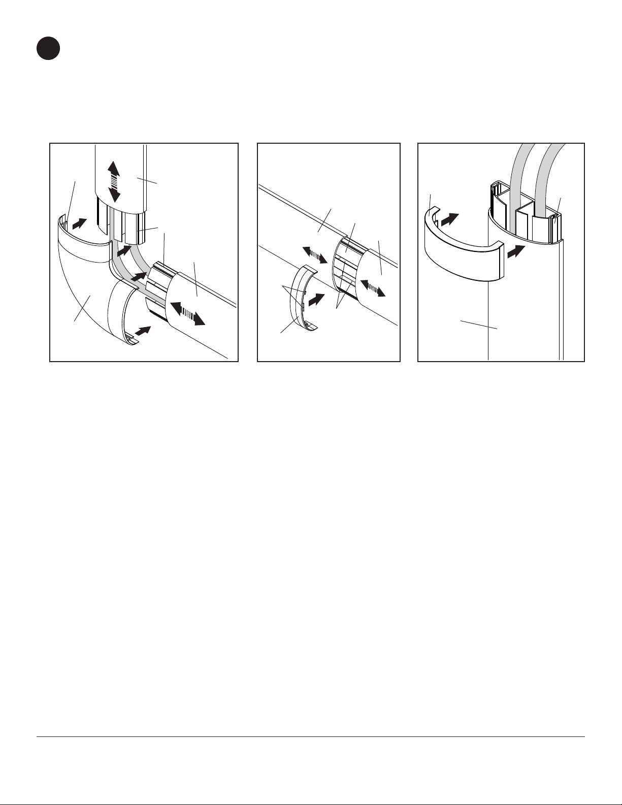
Attach corner cover (B) to mounting bases (C) by guiding corner cover fl anges into slide channels of mounting
6
bases as shown in fi gure 6.1. Note: It may be necessary to slide covers (A) apart to allow corner cover to fi t. After
corner cover is attached, slide covers under corner cover until cover fl anges contact fl anges of corner cover.
Slide apart covers (A) and align tabs of cover joint (D) with channels in mounting base (C) and attach as shown in
fi gure 6.2. Slide covers back for a fl ush fi t.
Attach end caps (E) to mounting bases (C) as shown in fi gure 6.3.
FLANGES
B
fi g 6.1
A
C
A
fi g 6.2
TABS
D
A
C
CHANNELS
A
fi g 6.3
E
A
C
Visit the Peerless Web Site at www.peerless-av.com
8 of 24
All other brand and product names are trademarks or registered trademarks of their respective owners.
ISSUED: 04-23-08 SHEET #: 120-9046-3 09-28-12
For customer care call 1-800-865-2112
© 2008, Peerless Industries, Inc. All rights reserved.
 Loading...