


Installation and Assembly:
Paramount™ Pivot for 22" - 40" (56 - 102 cm) LCD screens
Models: PP740, PWV240/BK
Features:
• Fits 22" - 40" (56 - 102 cm) LCD screens
• Two tensionable pivot points for extensive adjustment of
viewing angle
®
• VESA
• Frees up space by folding flat against the wall
75/100/200 x 100/200 x 200 compatible
U
©
L
I
USC
D
2
:
6
0
7
0
8
0
1
0
0
Max Load Capacity: 80lb (36 kg)
ISSUED: 02-05-09 SHEET #: 202-9312-1

NOTE: Read entire instruction sheet before you start installation and assembly.
WARNING
• Do not begin to install your Peerless product until you have read and understood the instructions and warnings
contained in this Installation Sheet. If you have any questions regarding any of the instructions or warnings, for US
customers please call Peerless customer care at 1-800-865-2112, for all international customers, please contact
your local distributor.
• This product should only be installed by someone of good mechanical aptitude, has experience with basic building
construction, and fully understands these instructions.
• Make sure that the supporting surface will safely support the combined load of the equipment and all attached
hardware and components.
• Never exceed the Maximum Load Capacity. See page one.
• If mounting to wood wall studs, make sure that mounting screws are anchored into the center of the studs. Use of
an "edge to edge" stud finder is highly recommended.
• Always use an assistant or mechanical lifting equipment to safely lift and position equipment.
• Tighten screws firmly, but do not overtighten. Overtightening can damage the items, greatly reducing their holding
power.
• This product is intended for indoor use only. Use of this product outdoors could lead to product failure and personal
injury.
• This product was designed to be installed on the following wall construction only;
WALL CONSTRUCTION HARDWARE REQUIRED
• Wood Stud Included
• Wood Beam Included
• Solid Concrete Included
• Cinder Block Included
• Metal Stud Do not attach except with Peerless Metal Stud Accessory Kit - WSP490;
• Brick Contact Qualified Professional
• Other or unsure? Contact Qualified Professional
Tools Needed for Assembly
• stud finder ("edge to edge" stud finder is recommended)
• phillips screwdriver
• drill
• 5/16" (8 mm) bit for concrete and cinder block wall
• 5/32" (4 mm) bit for wood stud wall
• level
Table of Contents
Parts List.................................................................................................................................................................................3
Installation to Wood Stud Wall ................................................................................................................................................4
Installation to Solid Concrete and Cinder Block .....................................................................................................................5
®
Attaching Adapter Plate to Screen with VESA
Installing to Peerless LC or PLP Model Adapter Bracket .......................................................................................................8
Cord Management and Arm Tension Adjustment ................................................................................................................10
Mounting Pattern ..........................................................................................6
2 of 20
ISSUED: 02-05-09 SHEET #: 202-9312-1

Before you begin, make sure all parts shown are included with your product.
K
y
A
Parts List
Description
wall mount assembly
concrete anchor 2 590-0320
B
retaining spacer 4 590-5005
C
1/4-20 x 13 mm flat head phillips screw 2 520-1209
D
M4 x 10 mm phillips screw 4 504-9012
E
M4 x 20 mm phillips screw 4 504-9020
F
M6 x 12 mm phillips screw 4 520-1128
G
#14 x 63.5 mm flat head wood screw 2 520-1202
H
M6 x 20 mm phillips screw 4 520-9402
I
M6 x 30 mm phillips screw 4 510-9109
J
M5 x 6 mm phillips screw 5 520-1023
K
#10 flat washer 4 540-9400
L
hook bracket 1
M
adapter plate
N
#10-32 x 6 mm flat head phillips screw 1 520-1108
O
P cable tie 1 560-1725
Parts may appear slightly different than illustrated.
A
BE
PWV240/B
PP740
Part #
Qt
.
095-0545-GB
1
095-P1346
095-P1322
1
CF
D
G
M
H
IJ
NO
3 of 20
P
KL
ISSUED: 02-05-09 SHEET #: 202-9312-1
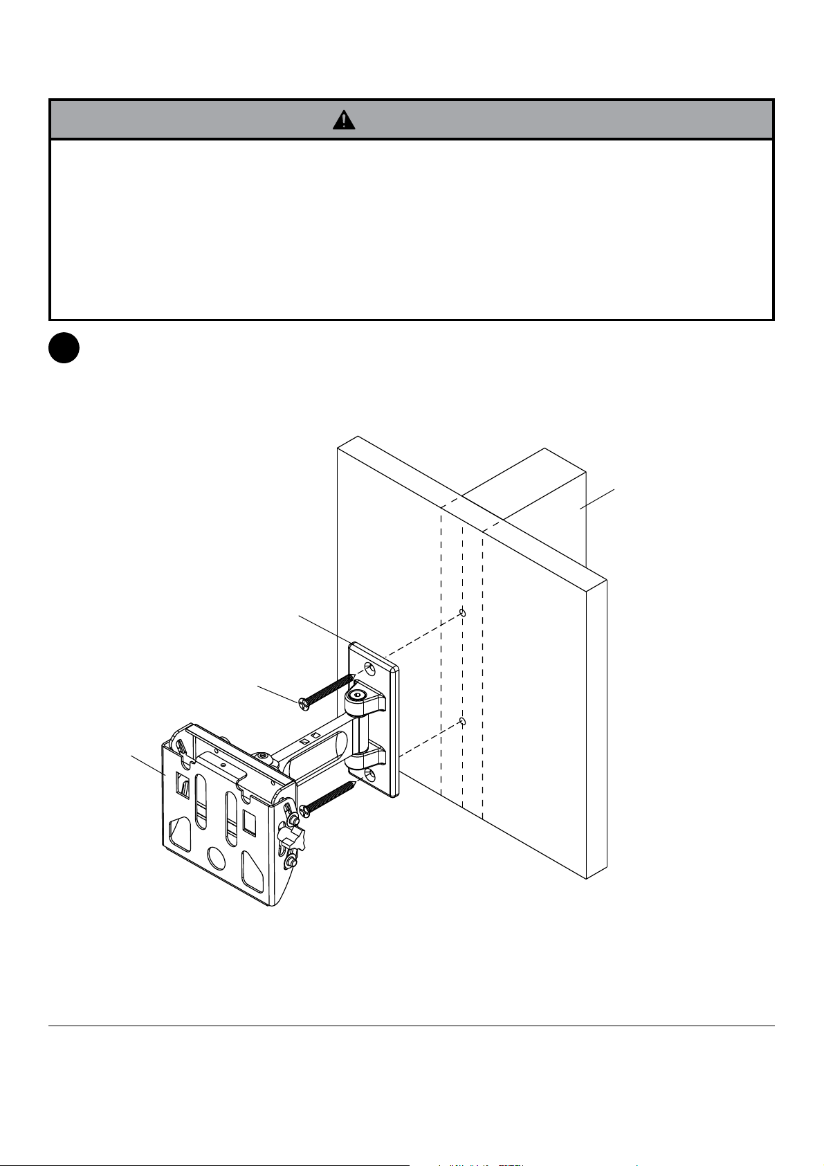
Installation to Wood Stud Wall
WARNING
• Installer must verify that the supporting surface will safely support the combined load of the equipment and all
attached hardware and components.
• Tighten wood screws so that wall plate is firmly attached, but do not overtighten. Overtightening can damage the
screws, greatly reducing their holding power.
• Never tighten in excess of 80 in. • lb (9 N.M.).
• Make sure that mounting screws are anchored into the center of the stud. The use of an "edge to edge" stud finder
is highly recommended.
• Hardware provided is for attachment of mount through standard thickness drywall or plaster into wood studs. Install-
ers are responsible to provide hardware for other types of mounting situations (not UL approved).
Using a stud finder, locate and mark the edges of the wood stud used in mounting this product. Use of an edge to
1
edge stud finder is highly recommended. Use a level to draw a vertical line down the center of the stud. Use wall
plate as template to mark center of holes along the vertical line. Drill two 5/32" (4 mm) dia. holes 2.5" (64 mm)
deep. Attach wall mount (A) to wall using two #14 x 63.5 mm flat head wood screws (H) as shown.
Skip to step 2 on page 6.
A
WOOD STUD WALL
WALL PLATE
H
4 of 20
ISSUED: 02-05-09 SHEET #: 202-9312-1

Installation to Solid Concrete and Cinder Block
WARNING
• When installing Peerless wall mounts on cinder block, verify that you have a minimum of 1-3/8" of actual concrete
thickness in the hole to be used for the concrete anchors. Do not drill into mortar joints! Be sure to mount in a
solid part of the block, generally 1" minimum from the side of the block. Cinder block must meet ASTM C-90
specifications. It is suggested that a standard electric drill on slow setting is used to drill the hole instead of a
hammer drill to avoid breaking out the back of the hole when entering a void or cavity.
• Concrete must be 2000 psi density minimum. Lighter density concrete may not hold concrete anchor.
• Make sure that the supporting surface will safely support the combined load of the equipment and all attached
hardware and components.
Level and use wall plate as template to mark center
1
of holes.
minimum depth of 2.5" (64 mm). Insert anchors (B)
in holes flush with wall. Place wall mount (A) over
anchors and secure with wood screws (H). Make
sure wall mount is level, and tighten all fasteners.
Drill two 5/16" (8 mm) dia. holes to a
1
B
Drill holes and insert anchors (B).
concrete
surface
WARNING
• Tighten screws so that wall plate is firmly attached,
but do not overtighten. Overtightening can damage
the screws, greatly reducing their holding power.
• Never tighten in excess of 80 in. • lb (9 N.M.).
WARNING
• Always attach concrete expansion anchors directly
to load-bearing concrete.
• Never attach concrete expansion anchors to
concrete covered with plaster, drywall, or other
finishing material. If mounting to concrete surfaces
covered with a finishing surface is unavoidable,
the finishing surface must be counterbored as
shown below. Be sure concrete anchors do not
pull away from concrete when tightening screws. If
plaster/drywall is thicker than 5/8" (16 mm), custom
fasteners must be supplied by installer.
INCORRECT CORRECT
wall
plate
concrete
wall
plate
concrete
2
A
H
Place plate (A) over anchors (B) and secure with screws (H).
3
Tighten all fasteners.
SOLID CONCRETE
CINDER BLOCK
B
WALL PLATE
B
CUTAWAY VIEW
plaster/
dry wall
plaster/
dry wall
5 of 20
H
A
ISSUED: 02-05-09 SHEET #: 202-9312-1

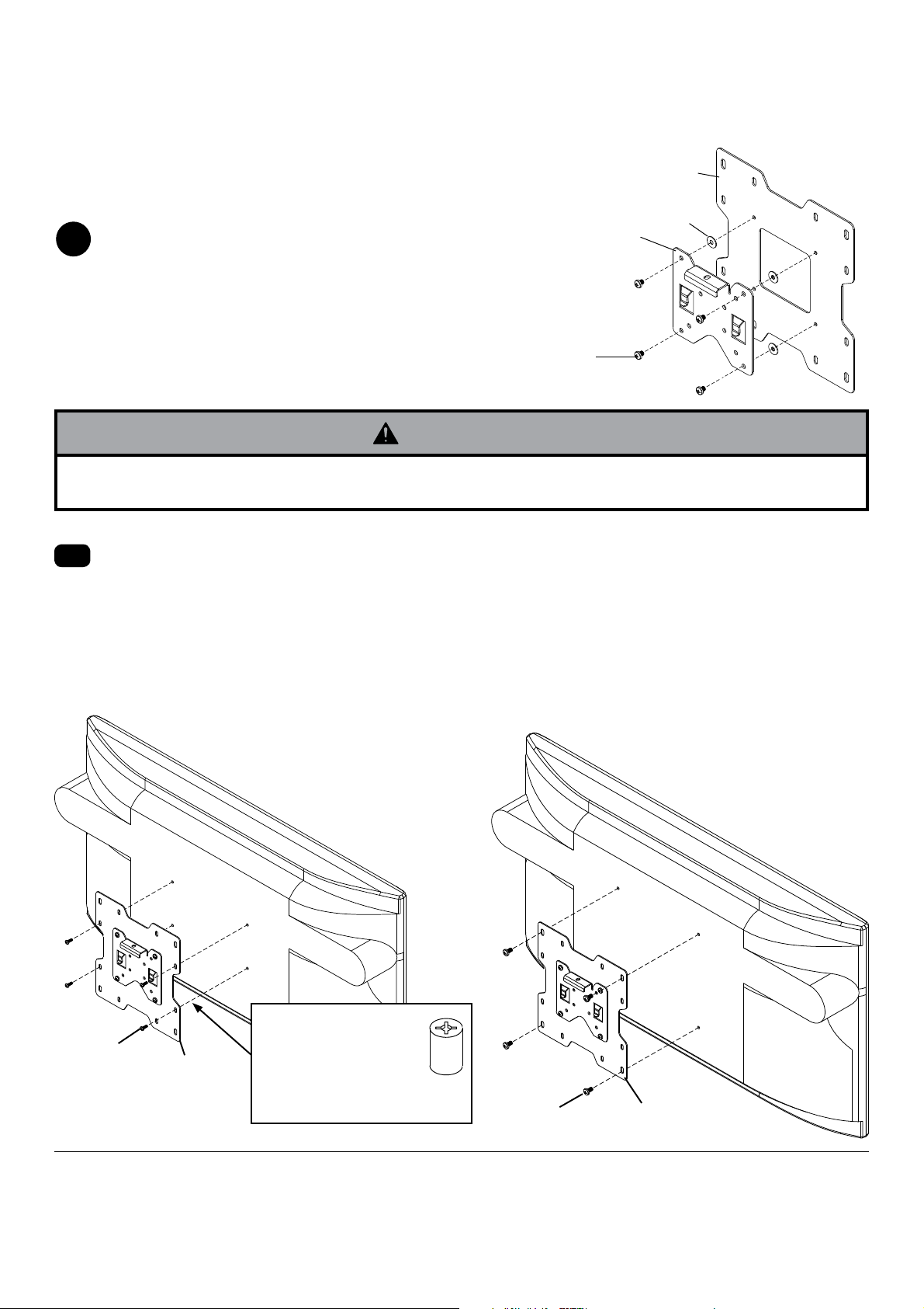
Attaching Adapter Plate to Screen with VESA® 200 x 100
or 200 x 200 Mounting Pattern
NOTE: For VESA 75 mm and 100 mm patterns, see following page.
Attach hook bracket (M) to adapter plate (N) using
2
four M5 x 6 mm screws (K) and #10 washers (L) as
shown.
M
N
L
K
WARNING
• If screws don't get three complete turns in the screen inserts or if screws bottom out and adapter plate is still not
tightly secured, damage may occur to screen or product may fail.
FOR VESA® 200 x 100 MOUNTING PATTERN:
Choose hole pattern as shown below. Attach
2-1
adapter plate (N) to back of screen using four M4 x
10 mm screws (E) as shown below.
*NOTE: If screw (E) gets less than three threads
of engagement, attach adapter plate (N) to back of
screen using four M4 x 20 mm screws (F) and four
spacers (C) as indicated below.
Skip to step 3 on page 9.
FOR VESA® 200 x 200 MOUNTING PATTERN:
Choose hole pattern as shown below. Attach adapter
plate (N) to back of screen using four M6 x 12 mm
screws (G) as shown below.
*NOTE: If screw (G) gets less than three threads
of engagement, attach adapter plate (N) to back of
screen using four M6 x 20 mm screws (I). If screw (I)
still gets less than three threads of engagement, use
four M6 x 30 mm screws (J).
Skip to step 3 on page 9.
E
*For screens with a
N
hole pattern in a pocket,
spacers (C) go between
adapter plate (N) and
screen.
C
6 of 20
G
N
ISSUED: 02-05-09 SHEET #: 202-9312-1

Attaching Hook Bracket to Screen with VESA® 75 or 100 Mounting Pattern
WARNING
• If screws don't get three complete turns in the screen inserts or if screws bottom out and bracket is still not tightly
secured, damage may occur to screen or product may fail.
FOR VESA® 75 MOUNTING PATTERN:
Choose hole pattern as shown below. Attach hook
2
bracket (M) to back of screen using four M4 x 10
mm screws (E) as shown below.
*NOTE: If hole pattern is in a pocket, attach hook
bracket (M) to back of screen using four M4 x 20
mm screws (F) and four retaining spacers (C) as
indicated below.
M
FOR VESA® 100 MOUNTING PATTERN:
Choose hole pattern as shown below. Attach hook
bracket (M) to back of screen using four M4 x 10
mm screws (E) as shown below.
E
*For screens with a
hole pattern in a pocket,
spacers (C) go between
hook bracket (M) and
screen.
C
7 of 20
M
E
ISSUED: 02-05-09 SHEET #: 202-9312-1

For screen compatibility please refer to the LCD or plasma interface list on our website www.peerlessmounts.com or
call customer care for a screen specific adapter bracket LC or PLP models (not UL evaluated).
FOR INSTALLING TO PEERLESS LC MODEL ADAPTER BRACKET
NOTE: Refer to LC model adapter bracket instruction sheet for attachment of adapter bracket to screen.
NOTE: Either M5 x 6 mm or M5 x 10 mm screws are included with the LC model adapter bracket.
WARNING
• If screws don't get three complete turns in the screen inserts or if screws bottom out and bracket is still not tightly
secured, damage may occur to screen or product may fail.
Attach hook bracket (M) to adapter bracket using four M5 x 6 mm or M5 x 10 mm screws.
2
GENERIC ADAPTER BRACKET
M
M5 X 6 MM OR M5 X 10 MM SCREW
FOR INSTALLING TO PEERLESS PLP MODEL ADAPTER BRACKET
NOTE: Refer to PLP model adapter bracket instruction sheet for attachment of adapter bracket to screen.
NOTE: M5 x 10 mm screws are included with the PLP model adapter bracket.
Attach hook bracket (M) to adapter bracket using four M5 x 10 mm screws.
2
GENERIC ADAPTER BRACKET
M
M5 X 10 MM SCREW
8 of 20
ISSUED: 02-05-09 SHEET #: 202-9312-1

Installing and Removing Flat Panel Screen
To attach screen to wall mount (A), lower hook
3
bracket (M) with screen at an angle into pockets of
wall mount as shown in figure 3.1. Once clips are
engaged, push down to seat clips in pockets as
shown in figure 3.2. Insert and tighten M5 phillips
screw (K) to lock screen to wall mount as shown in
figure 3.3.
To remove screen from mount, loosen screw (K)
and lift screen off of mount.
SCREEN
K
M
CLIP
WARNING
• Do not lift more weight than you can handle. Use ad-
ditional man power or mechanical lifting equipment
to safely handle placement of the screen.
• Failure to lock hook bracket (M) with screw (K) can
cause screen to come off mount if hit accidentally.
CAUTION
• Do not tighten screws with excessive force.
Overtightening can cause damage to mount. Tighten
screws to 20 in. • lb (2.26 N.M.) maximum torque.
Adjust tension knob on side of mount shown in
4
fig. 4.1 to desired tension to balance your screen
size and weight.
Push or pull from top or bottom of screen to adjust
tilt as shown. The tilt can be adjusted to a maximum
of 15° forward or 5° backward.
fig. 3.1
POCKET
A
fig. 3.3
fig. 3.2
CAUTION
• Do not tighten screws with excessive force.
Overtightening can cause damage to mount. Tighten
screws to 40 in. • lb (4.5 N.M.) maximum torque.
CAUTION
• Be careful not to pinch fingers when opening and
closing mount from the wall.
Roll screen to desired position (5° clockwise or
4-1
counter-clockwise). Insert #10-32 x 6 mm flat head
phillips screw (O) to lock screen into position as
shown in figure 4.2.
9 of 20
TENSION KNOB
O
fig. 4.2
fig. 4.1
ISSUED: 02-05-09 SHEET #: 202-9312-1

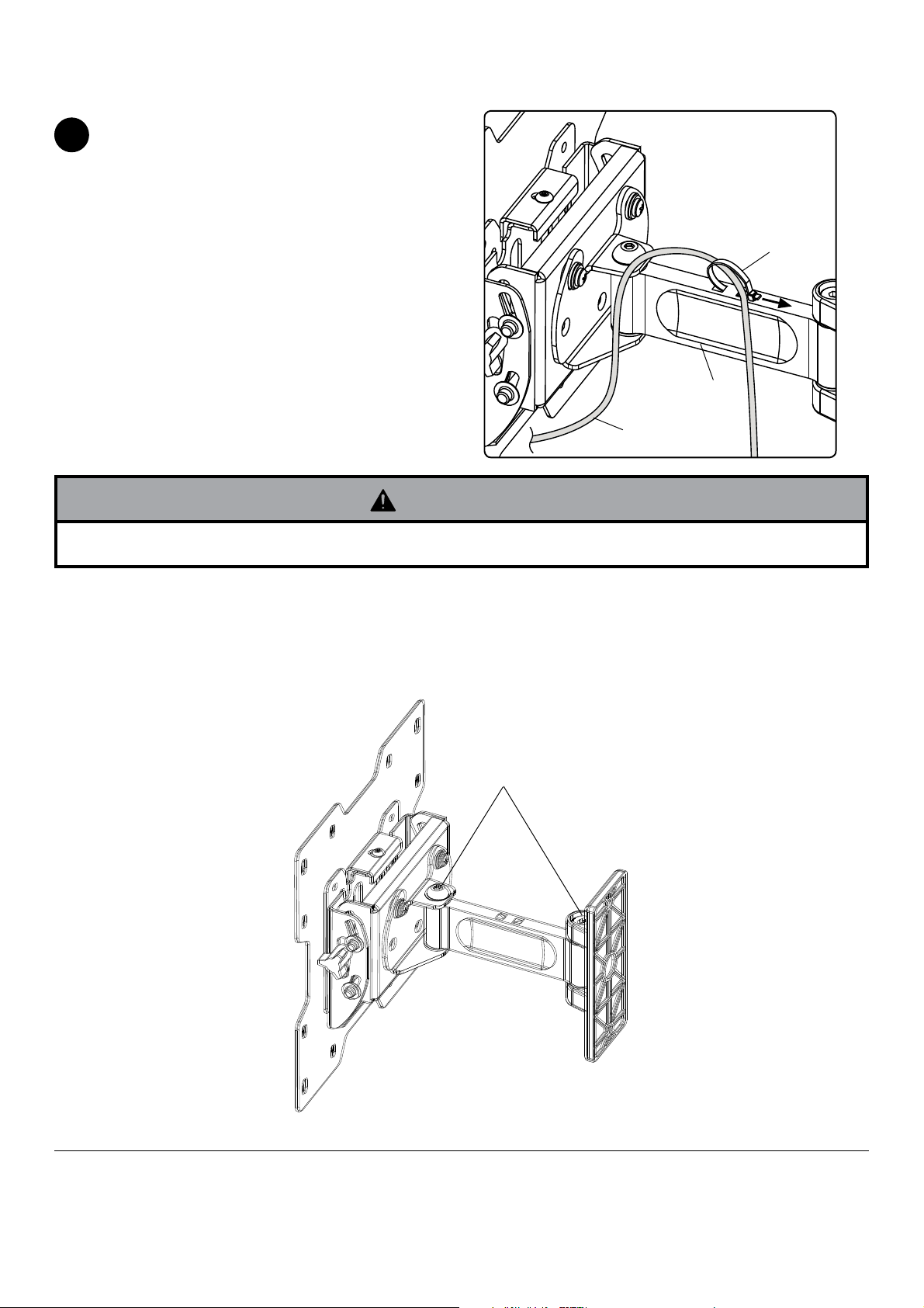
Cord Management and Arm Tension Adjustment
CORD MANAGEMENT: Tighten cable to top of wall
5
mount assembly arm (A) using cable tie (P).
P
A
CORD
WARNING
• Do not remove screw or loosen screw until it is no longer engaged with the mount. Doing so may cause the screen
to fall.
ARM TENSION ADJUSTMENT: If more or less tension is desired in the arm pivot points, do the following:
• To increase tension, turn tension screw(s) clockwise with allen wrench.
• To reduce tension, turn tension screw(s) counter-clockwise with allen wrench.
NOTE: Do not turn more than half a turn.
TENSION
SCREWS
10 of 20
ISSUED: 02-05-09 SHEET #: 202-9312-1

Anbringung und Zusammenbau:
Paramount™-Schwenkhalterung für LCD-Bildschirme
von 23-40 Zoll (56 - 102 cm)
Models: PP740, PWV240/BK
Merkmale:
• Für LCD-Bildschirme von 22 bis 40 Zoll (56 - 102 cm)
• Zwei spannbare Gelenke bieten vielseitige
Einstellmöglichkeiten des Betrachtungswinkels
• Kompatibel mit VESA® 75/100/200 x 100/200 x 200
• Flach an die Wand klappbare Ausführung spart Platz
U
©
L
I
USC
D
2
:
6
0
7
0
8
0
1
0
0
Maximale Tragfähigkeit: 80lb (36 kg)
AUSGEGEBEN: 02-05-09 BLATT NR.: 202-9312-1

HINWEIS: Lesen Sie die gesamte Anleitung, bevor Sie mit der Anbringung und dem Zusammenbau beginnen.
ACHTUNG
• Beginnen Sie mit der Anbringung Ihres Peerless-Produkts erst, nachdem Sie die in dieser Montageanleitung enthaltenen Anleitungen und
Achtungshinweise gelesen und sich gründlich mit ihnen vertraut gemacht haben. Falls Sie Fragen hinsichtlich irgendeiner der Anleitungen oder
Achtungshinweise haben, wenden Sie sich in den USA bitte an den Peerless-Kundendienst unter der Rufnummer 1-800-865-2112. Kunden im
Ausland wenden sich bitte an den örtlichen Vertragshändler.
• Dieses Produkt darf nur von Personen mit guten mechanischen Fähigkeiten montiert werden, die über Erfahrung in den Grundlagen der
Baukonstruktion verfügen und diese Anleitungen vollkommen verstehen.
• Vergewissern Sie sich, dass die tragende Fläche das Gesamtgewicht der Geräte und allen daran angebrachten Befestigungsteilen und
Komponenten sicher tragen kann.
• Die maximale Tragfähigkeit darf niemals überschritten werden. Siehe Seite 11.
• Achten Sie bei der Anbringung an Holzständern darauf, dass die Befestigungsschrauben jeweils in der Mitte der Holzständer verankert sind. Am
besten eignet sich ein Balkenfinder mit genauer Kantenanzeige.
• Ziehen Sie immer eine zusätzliche Person heran oder verwenden Sie mechanische Hebegeräte, um Geräte sicher zu heben und zu positionieren.
• Ziehen Sie die Schrauben fest an, ohne sie zu überdrehen. Durch Überdrehen können die Teile beschädigt werden, wodurch ihr Haltevermögen
stark reduziert wird.
• Dieses Produkt ist nur für den Gebrauch innerhalb von Gebäuden bestimmt. Eine Verwendung dieses Produkts im Freien kann zu Produktausfall
und Personenschaden führen.
• Dieses Produkt wurde nur für die Anbringung an den folgenden Wandkonstruktionen ausgelegt:
WANDKONSTRUKTION ERFORDERLICHE BEFESTIGUNGSTEILE
• HOLZSTÄNDER INBEGRIFFEN
• HOLZBALKEN INBEGRIFFEN
• MASSIVBETON INBEGRIFFEN
• PORENBETONSTEIN INBEGRIFFEN
• METALLSTÄNDER NUR MIT METALLSTÄNDER-ZUBEHÖRSATZ VON PEERLESS ANBRINGEN - WSP490;
• ZIEGEL QUALIFIZIERTEN FACHMANN KONSULTIEREN
• ANDERE ODER NICHT SICHER? QUALIFIZIERTEN FACHMANN KONSULTIEREN
Für den Zusammenbau erforderliche Werkzeuge
• Balkenfinder (Balkenfinder mit genauer Kantenanzeige empfohlen)
• Kreuzschlitzschraubendreher
• Bohrer
• 5/16 Zoll (8 mm) Bit für Beton- und Porenbetonsteinwand
• 5/32 Zoll (4 mm) Bit für Holzständerwand
• Wasserwaage
Inhaltsverzeichnis
Teileliste ................................................................................................................................................................................13
Anbringung an Wand Holzständerreihen ..............................................................................................................................14
Anbringung an Massivbeton oder Porenbetonstein .............................................................................................................15
Befestigung der Adapterplatte am Bildschirm unter Verwendung von VESA-Montagemuster .............................................16
Befestigung an Peerless-Adapterhalterung Modell LC oder PLP .........................................................................................18
Kabelführung und Einstellung der Armspannung ................................................................................................................20
12 of 20
AUSGEGEBEN: 02-05-09 BLATT NR.: 202-9312-1

Bevor Sie beginnen, stellen Sie sicher, dass alle Teile gezeigt werden, die mit Ihrem Produkt.
K
A
r
Teileliste
Beschreibung
Wandhaltereinheit
betondübel 2 590-0320
B
beibehaltung abstandhalter 4 590-5005
C
1/4-20 x 13 Zoll Kreuzschlitz-Senkkopfschraube 2 520-1209
D
M4 x 10 mm phillips-schraube 4 504-9012
E
M4 x 20 mm phillips-schraube 4 504-9020
F
M6 x 12 mm phillips-schraube 4 520-1128
G
#14 x 63.5 Zoll Kreuzschlitz-Senkkopfschraube 2 520-1202
H
M6 x 20 mm phillips-schraube 4 520-9402
I
M6 x 30 mm phillips-schraube 4 510-9109
J
M5 x 6 mm phillips-schraube 5 520-1023
K
#10 flache Scheibe 4 540-9400
L
Hakenhalterung 1
M
Adapterplatte
N
#10-32 x 6 Zoll Kreuzschlitz-Senkkopfschraube 1 520-1108
O
P Kabelbinde
DieTeile können leicht anders als dargestellt.
A
BE
Anz. Teilenr #
1
1
1 560-1725
CF
PWV240/B
PP740
095-0545-GB
095-P1346
095-P1322
D
G
M
H
IJ
NO
13 of 20
P
KL
AUSGEGEBEN: 02-05-09 BLATT NR.: 202-9312-1

Anbringung an Wand Holzständerreihen
ACHTUNG
• Bei der Anbringung muss darauf geachtet werden, dass die Wand die kombinierte Last von Bildschirm und allen Befestigungsteilen und
-komponenten tragen kann.
• Ziehen Sie die Schrauben fest genug an, dass die Wandplatte sicher befestigt ist, doch ohne sie zu überdrehen. Durch Überdrehen können die
Schrauben beschädigt werden, wodurch ihr Haltevermögen stark reduziert wird.
• Das Drehmoment darf 80 in. • lb (9 Nm.) auf keinen Fall überschreiten.
• Achten Sie darauf, dass die Befestigungsschrauben jeweils in der Mitte der Holzständer verankert werden. Am besten eignet sich ein Balkenfinder
mit genauer Kantenanzeige.
• Die mitgelieferten Befestigungsteile sind für die Befestigung des Halters durch Trocken- oder Putzwand standardmäßiger Stärke in Holzständer
vorgesehen. Für die Anbringung an anders konstruierten Wänden müssen andere (nicht UL-zugelassene) Befestigungsteile verwendet werden.
Hinweis: Wenn ein Bildschirm mit einem Gewicht über 45 kg montiert werden soll, wird die Befestigung an drei Holzständern nahegelegt.
Fahren Sie auf Seite 6 fort. Bestimmen Sie die Kanten der Ständer mithilfe eines Balkenfinders. Am besten eignet sich ein Balkenfinder mit
1
genauer Kantenanzeige. Verwenden Sie die Kanten als Richtlinie und ziehen Sie eine senkrechte Linie entlang der Mitte der Ständer. Halten
Sie die Wandplatte als Schablone an die Wand. Die oberen Montageschlitze sollten sich oberhalb der gewünschten Bildschirmmitte befinden
(siehe Abbildung 1.1). HINWEIS: Die Position der Wandplatte hängt von der Bildschirmneigung ab. Richten Sie die Platte waagerecht aus und
markieren Sie den Mittelpunkt der zwei Montagebohrungen. Achten Sie darauf, dass die Montagebohrungen sich jeweils auf der Mittellinie der
Holzständer befinden. Bohren Sie zwei Löcher mit einem Durchmesser von 4 mm (5/32 Zoll) und einer Tiefe von 64 mm (2,5 Zoll). Achten Sie
darauf, dass die Wandplatte waagerecht ist und befestigen Sie sie wie in Abbildung 1.2 gezeigt mit zwei Nr. 14 x 63,5 mm Holzschrauben (C).
FAHREN SIE MIT SCHRITT 2 AUF SEITE 16 FORT.
A
HOLZSTÄNDERWAND
WANDPLATTE
H
14 of 20
AUSGEGEBEN: 02-05-09 BLATT NR.: 202-9312-1

Anbringung an Massivbeton oder Porenbetonstein
ACHTUNG
• Bei der Anbringung von Peerless-Wandhaltern an Porenbetonstein muss sichergestellt werden, dass die tatsächliche Stärke des Betons, in
den das Loch für die Betondübel gebohrt wird, mindestens 35 mm (1 3/8 Zoll) beträgt. Bohren Sie nicht in Mörtelfugen! Achten Sie darauf,
dass die Anbringung an einem massiven Teil des Blocks erfolgt, im Allgemeinen mindestens 25 mm (1 Zoll) von der Blockseite entfernt. Die
Porenbetonsteine müssen den Spezifikationen der ASTM-Norm C-90 entsprechen. Wir empfehlen, zum Bohren des Lochs anstelle eines
Schlagbohrers einen standardmäßigen Elektrobohrer bei niedriger Einstellung zu verwenden, um zu verhindern, dass die Bohrungsrückseite beim
Eintritt in einen Leer- oder Hohlraum ausbricht.
• Die Betondruckfestigkeit muss mindestens 2000 psi betragen. In Beton mit geringerer Druckfestigkeit kann der Betondübel u. U. nicht halten.
• Vergewissern Sie sich, dass die Wand das Vierfache des Gesamtgewichts von Geräten und allen daran angebrachten Befestigungsteilen und
Komponenten sicher tragen kann.
Achten Sie darauf, dass die Wandplatte (A) waagerecht ist
und verwenden Sie sie als Schablone zum Markieren der
1
beiden Montagebohrungen. Bohren Sie zwei Löcher mit einem
Durchmesser von 8 mm (5/16 Zoll) und einer Mindesttiefe von
64 mm (2,5 Zoll). Stecken Sie Dübel (B) in die Löcher, bis diese
bündig mit der Wand abschließen (siehe Abbildung rechts). Halten
Sie die Wandplatte auf den Dübeln fest und befestigen Sie sie mit
zwei Nr. 14 x 63,5 mm Schrauben (H). Richten Sie sie waagerecht
aus und ziehen Sie dann sämtliche Befestigungsteile an.
1
Bohren Sie Löcher und setzen Sie die Dübel (D) ein.
BEFESTIGUNGSFLÄCHE
B
ACHTUNG
• Ziehen Sie die Schrauben fest genug an, dass die Wandplatte
sicher befestigt ist, doch ohne sie zu überdrehen. Durch
Überdrehen können die Schrauben beschädigt werden, wodurch ihr
Haltevermögen stark reduziert wird.
• Das Drehmoment darf 80 in. • lb (9 Nm.) auf keinen Fall
überschreiten.
ACHTUNG
• Betonspreizdübel müssen stets direkt am tragenden Beton
angebracht werden.
• Betonspreizdübel dürfen auf keinen Fall an Beton befestigt
werden, der mit Verputz, Trockenwandmaterial oder anderem
Deckschichtmaterial bedeckt ist. Falls es nicht vermeiden lässt,
die Montage an einer Betonfläche mit Deckschicht vorzunehmen,
muss wie nachstehend dargestellt eine Senkung in die Deckschicht
gebohrt werden. Vergewissern Sie sich, dass die Betondübel beim
Anziehen der Schrauben nicht vom Beton weg gezogen werden.
Falls der Verputz bzw. das Trockenwandmaterial dicker ist als 16
mm (5/8 Zoll), müssen von der für die Montage zuständigen Person
Spezialbefestigungsteile bereitgestellt werden.
FALSCH RICHTIG
WAND-
PLATTE
BETON
WAND-
PLATTE
BETON
H
A
B
2
Halten Sie die Platte (A) über die Dübel (B) und befestigen Sie sie
mit Schrauben (H).
3
Ziehen Sie alle Befestigungsteile an.
MASSIVBETON
PORENBETONSTEIN
B
SCHNITTANSICHT
VERPUTZ/
RIGIPS
VERPUTZ/
RIGIPS
15 of 20
WANDPLATTE
H
A
AUSGEGEBEN: 02-05-09 BLATT NR.: 202-9312-1
BEFESTIGUNG VON ADAPTERPLATTE AN BILDSCHIRM
UNTER VERWENDUNG VON VESA®-MONTAGEMUSTER
200 X 100 ODER 200 X 200
HINWEIS: DIE VESA-MUSTER 75 MM UND 100 MM SIND AUF DER
FOLGENDEN SEITE AUFGEFÜHRT.
Bringen Sie die Hakenhalterung (M) mit vier M5 x 6 mm Schrauben (K) und Scheiben Nr. 10 (L) wie dargestellt an der Adapter-
2
platte (N) an.
M
N
L
K
ACHTUNG
• Sind die Schrauben nicht um drei volle Umdrehungen in die Löcher des Bildschirms eingeschraubt oder stoßen sie unten an und die Halterung
ist noch immer nicht sicher befestigt, kann der Bildschirm beschädigt werden oder das Produkt kann versagen.
BEI MONTAGEMUSTER VESA® 200 x 100:
Wählen Sie das Lochmuster (siehe Abbildung weiter unten).
2-1
Befestigen Sie die Adapterplatte (N) mit Hilfe von vier M4 x 10 mm
Schrauben (E) wie unten dargestellt an der Rückseite des Bildschirms.
*Hinweis: Wenn die Schraube (E) sich um weniger als drei
Gewindegänge einschrauben lässt, bringen Sie die Adapterplatte (N)
mit Hilfe von vier M4 x 20 mm Schrauben (F) und vier Abstandhaltern
(C) wie unten gezeigt an der Rückseite des Bildschirms an.
MIT SCHRITT 3 AUF SEITE 19 FORTFAHREN
BEI MONTAGEMUSTER VESA® 200 x 200:
Wählen Sie das Lochmuster (siehe Abbildung weiter unten).
Befestigen Sie die Adapterplatte (N) mit Hilfe von vier M6 x 12
mm Schrauben (G) wie unten dargestellt an der Rückseite des
Bildschirms. *Hinweis: Falls die Schraube (G) sich um weniger
als drei Gewindegänge einschrauben lässt, bringen Sie die
Adapterplatte (N) mit Hilfe von vier M6 x 20 mm Schrauben (I)
an der Rückseite des Bildschirms an. Falls die Schraube (I) sich
noch immer um weniger als drei Gewindegänge einschrauben
lässt, verwenden Sie vier M6 x 30 mm Schrauben (J).
MIT SCHRITT 3 AUF SEITE 19 FORTFAHREN
E
N
*Bei Bildschirmen mit Lochmuster in einer Vertiefung
werden Abstandhalter (C)
zwischen Hakenhalterung
(M) und Bildschirm verwendet.
C
16 of 20
G
N
AUSGEGEBEN: 02-05-09 BLATT NR.: 202-9312-1

Befestigung der Hakenhalterung am Bildschirm unter Verwendung von
Montagemuster VESA® 75 oder 100
ACHTUNG
• Sind die Schrauben nicht um drei volle Umdrehungen in die Löcher des Bildschirms eingeschraubt oder stoßen sie unten an und die Halterung
ist noch immer nicht sicher befestigt, kann der Bildschirm beschädigt werden oder das Produkt kann versagen.
BEI MONTAGEMUSTER VESA® 75:
Wählen Sie das Lochmuster (siehe Abbildung weiter unten).
2
Befestigen Sie die Hakenhalterung (M) mit Hilfe von vier M4 x 10
mm Schrauben (E) wie unten dargestellt an der Rückseite des
Bildschirms.
*Hinweis: Wenn das Lochmuster sich in einer Vertiefung befindet, bringen Sie die Hakenhalterung (M) mit Hilfe von vier M4
x 20 mm Schrauben (F) und vier Abstandhaltern (C) wie unten
dargestellt an der Rückseite des Bildschirms an.
M
BEI MONTAGEMUSTER VESA® 100:
Wählen Sie das Lochmuster (siehe Abbildung weiter unten).
Befestigen Sie die Hakenhalterung (M) mit Hilfe von vier M4 x 10
mm Schrauben (E) wie unten dargestellt an der Rückseite des
Bildschirms.
E
*Bei Bildschirmen mit Lochmuster in einer Vertiefung
werden Abstandhalter (C)
zwischen Hakenhalterung
(M) und Bildschirm verwendet.
C
17 of 20
M
E
AUSGEGEBEN: 02-05-09 BLATT NR.: 202-9312-1

Die Schnittstellenliste für LCD- oder Plasmabildschirme auf unserer Website www.peerlessmounts.com gibt Auskunft über die Kompatibilität Ihres
Bildschirms. Sie können sich auch telefonisch mit unserem Kundendienst in Verbindung setzen und eine bildschirmspezifische Adapterhalterung des
Modells LC oder PLP anfordern (nicht von UL geprüft).
BEFESTIGUNG AN PEERLESS-ADAPTERHALTERUNG MODELL LC
Hinweis: Informationen zur Befestigung der Adapterhalterung am Bildschirm können dem Anleitungsblatt für die Adapterhalterung des Modells
LC entnommen werden.
Hinweis: Im Lieferumfang der Adapterhalterung des Modells LC sind M5 x 10 mm Schrauben enthalten.
Befestigen Sie die Hakenhalterung (M) mit Hilfe von vier M5 x 6 mm oder M5 x 10 mm.
ACHTUNG
• Sind die Schrauben nicht um drei volle Umdrehungen in die Löcher des Bildschirms eingeschraubt oder stoßen sie unten an und die Halterung
ist noch immer nicht sicher befestigt, kann der Bildschirm beschädigt werden oder das Produkt kann versagen.
Befestigen Sie die Hakenhalterung (M) mit Hilfe von vier M5 x 10 mm Schrauben an der Adapterhalterung.
2
GENERISCHE ADAPTERPLATT
M
SCHRAUBE M5 X 6 MM ODER M5 X 10 MM
BEFESTIGUNG AN PEERLESS-ADAPTERHALTERUNG MODELL PLP
Hinweis: Informationen zur Befestigung der Adapterhalterung am Bildschirm können dem Anleitungsblatt für die Adapterhalterung des Modells
PLP entnommen werden.
Hinweis: Im Lieferumfang der Adapterhalterung des Modells PLP sind M5 x 10 mm Schrauben enthalten.
Befestigen Sie die Hakenhalterung (M) mit Hilfe von vier M5 x 6 mm oder M5 x 10 mm.
Befestigen Sie die Hakenhalterung (M) mit Hilfe von vier M5 x 10 mm Schrauben an der Adapterhalterung.
2
GENERISCHE ADAPTERPLATTE
M
SCHRAUBE M5 X 10 MM
18 of 20
AUSGEGEBEN: 02-05-09 BLATT NR.: 202-9312-1

Anbringung und Abnahme des Flachbildschirms
Zur Befestigung des Bildschirms am Wandhalter (A) halten Sie
den Bildschirm schräg und senken die Hakenhalterung (M) wie in
3
Abbildung 3.1 dargestellt in die Aussparungen des Wandhalters
ab. Nachdem die Klemmen eingerastet sind, drücken Sie sie nach
unten, um sie in die Aussparungen einzupassen (siehe Abbildung
3.2). Setzen Sie die M5 Kreuzschlitzschraube (K) ein und ziehen
Sie sie fest, um den Bildschirm wie in Abbildung 3.3 dargestellt am
Wandhalter zu befestigen.
Zum Abnehmen des Bildschirms vom Halter lösen Sie die Schraube
(K) und heben den Bildschirm vom Halter ab.
BILDSCHIRM
K
M
KLEMME
ACHTUNG
• Heben Sie nicht schwerer, als Ihre Kräfte es zulassen. Ziehen
Sie eine zweite Person hinzu oder verwenden Sie mechanische
Hebegeräte, um die sichere Platzierung des Bildschirms zu
gewährleisten.
• Wenn die Hakenhalterung (M) nicht mit der Schraube (K) gesichert wird, kann der Bildschirm bei versehentlichem Anstoßen
vom Halter herabfallen.
VORSICHT
• Ziehen Sie die Schrauben nicht zu fest an. Durch Überdrehen
kann der Halter beschädigt werden. Das maximale Drehmoment
zum Festziehen der Schrauben darf 20 in • lb (2,26 Nm) nicht
überschreiten.
Stellen Sie den in Abbildung 4 auf der Halterseite dargestellten
Spannknopf auf die gewünschte Spannung für die Größe und das
4
Gewicht Ihres Bildschirms ein. Ziehen Sie an der Oberkante des
Bildschirms bzw. drücken Sie die Unterkante, um die Neigung
einzustellen (siehe Abbildung). Die maximale Neigung beträgt 15°
nach vorne bzw. 5° nach hinten.
VORSICHT
• Ziehen Sie die Schrauben nicht zu fest an. Durch Überdrehen
kann der Halter beschädigt werden. Das maximale Drehmoment
zum Festziehen der Schrauben darf 40 in • lb (4.5 Nm) nicht
überschreiten.
AUSSPARUNG
A
Addildung. 3.3
Addildung. 3.1 Addildung. 3.2
SPANNKNOPF
VORSICHT
• Achten Sie darauf, nicht kneifen, wenn die Finger
drücken Bildschirm aus dem Boden.
Bewegen Sie zum Einstellen der gewünschten Querneigung
4-1
den Bildschirm in die entsprechende Stellung (5° nach rechts
oder links). Setzen Sie die Nr. 10-32 x 1/2 Zoll KreuzschlitzSenkkopfschraube (O) ein, um den Bildschirm wie in Abbildung
4.2 dargestellt in der Position zu verriegeln.
Addildung. 4.1
19 of 20
O
Addildung. 4.2
AUSGEGEBEN: 02-05-09 BLATT NR.: 202-9312-1
Kabelführung und Einstellung der Armspannung
KABELFÜHRUNG: Befestigen Sie das Kabel mit Hilfe von Kabel-
bindern (P) an der Oberseite des Arms der Wandhaltereinheit (A).
5
P
A
KABEL
ACHTUNG
• Die Schraube darf nicht entfernt bzw. soweit gelöst werden, dass sie nicht mehr in den Halter eingreift, da ansonsten der Bildschirm herabfallen
kann.
lEinstellung der Armspannung: Wenn die Spannung in den Gelenken des Arms erhöht oder verringert werden soll, gehen Sie wie folgt vor:
• Zum Erhöhen der Spannung drehen Sie die Spannungsschraube(n) mit einem Inbusschlüssel nach rechts.
• Zum Verringern der Spannung drehen Sie die Spannungsschraube(n) mit einem
HINWEIS: Drehen Sie die Schraube um nicht mehr als eine halbe Umdrehung.
SPANNUNGSSCHRAUBEN
20 of 20
AUSGEGEBEN: 02-05-09 BLATT NR.: 202-9312-1
Alle anderen Marken- und Produktnamen sind eingetragene Marken der jeweiligen Eigentümer.
© 2009, Peerless Industries, Inc. Alle Rechte vorbehalten.
Peerless Industries, Inc.
3215 W. North Ave.
Melrose Park, IL 60160
www.peerlessmounts.com
 Loading...