

Installation and Assembly:
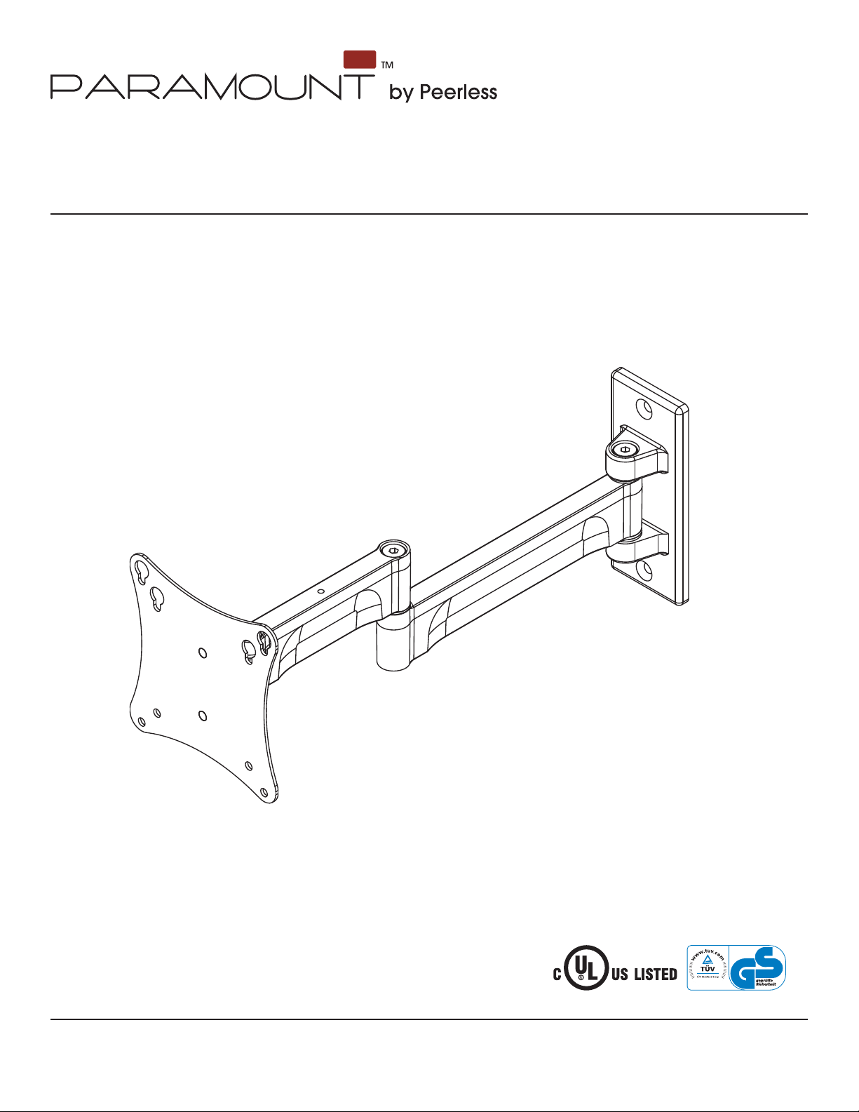
Paramount™ Articulating Wall Arm for 10" - 24" displays with
VESA 75 or 100 mounting patterns
Model: PA730, PA730-S
I
D
:
0
Max UL Load Capacity: 25 lb (11.34 kg)
2300 White Oak Circle • Aurora, Il 60502 • (800) 865-2112 • Fax: (800) 359-6500 • www.peerlessmounts.com
ISSUED: 06-18-07 SHEET #: 095-9269-6 02-15-12
2
6
7
0
8
0
1
0
0
Notes: Read entire instruction sheet before you start installation and assembly.
WARNING
• Do not begin to install your Peerless product until you have read and understood the instructions and warnings
contained in this Installation Sheet. If you have any questions regarding any of the instructions or warnings, for US
customers please call Peerless customer care at 1-800-865-2112, for all international customers, please contact
your local distributor.
• This product should only be installed by someone of good mechanical aptitude, has experience with basic building
construction, and fully understands these instructions.
• Make sure that the supporting surface will safely support the combined load of the equipment and all attached
hardware and components.
• Never exceed the Maximum UL Load Capacity. See page one.
• If mounting to wood wall studs, make sure that mounting screws are anchored into the center of the studs. Use of
an "edge to edge" stud fi nder is highly recommended.
• Always use an assistant or mechanical lifting equipment to safely lift and position equipment.
• Tighten screws fi rmly, but do not overtighten. Overtightening can damage the items, greatly reducing their holding
power.
• This product is intended for indoor use only. Use of this product outdoors could lead to product failure and personal
injury.
• This product was designed to be installed on the following wall construction only;
WALL CONSTRUCTION HARDWARE REQUIRED
• Wood Stud Included
• Wood Beam Included
• Solid Concrete Included
• Cinder Block Included
• Brick Contact Qualifi ed Professional (not evaluated by UL)
• Other or unsure? Contact Qualifi ed Professional
Tools Needed for Assembly
• stud fi nder ("edge to edge" stud fi nder is recommended)
• phillips screwdriver
• drill
• 5/16" (8mm) bit for concrete and cinder block wall
• 5/32" (4mm) bit for wood stud wall
• level
Table of Contents
Parts List.................................................................................................................................................................................3
Installation to Wood Stud Wall ................................................................................................................................................3
Installation to Solid Concrete and Cinder Block .....................................................................................................................4
Attaching Front Plate to Display Using VESA 75 or 100mm Mounting Patterns ....................................................................5
Cord management ..................................................................................................................................................................6
2 of 20
ISSUED: 06-18-07 SHEET #: 095-9269-6 02-15-12
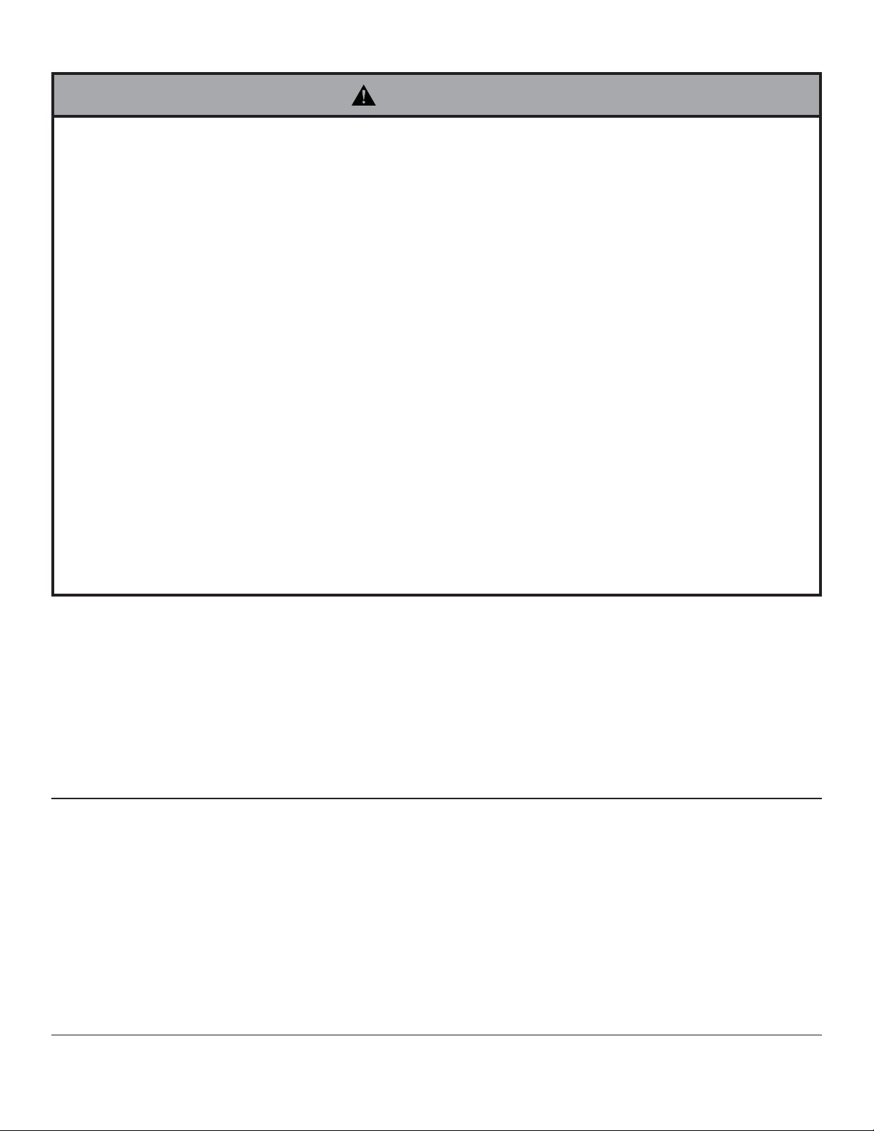
Before you begin, make sure all parts shown are included with your product.
Parts may appear slightly different than illustrated.
Parts List
Description Qty. Part # Part #
AA wall arm assembly 1 095-P1709 095-4709
A M4 x 12 mm phillips screw 4 504-9013 504-2013
B M4 x 20 mm phillips screw 4 504-9020 504-2014
C retaining spacer 4 590-5005 590-5003
D #14 x 2-1/2" wood screws 2 520-1202 520-2165
E 5 mm allen wrench 1 560-9640 560-9640
F concrete anchor 2 590-0320 590-0320
G cable ties 2 560-9711 560-2004
H cable tie anchor 2 590-1290 590-1290
I 3/16" allen wrench 1 560-0071 560-0071
J 8-32 x 1/4" flat head screw 2 520-1622 520-2622
AA
PA730 PA730-S
G
E
A
H
C
DFB
I
J
Installation to Wood Stud Wall
Using a stud fi nder, locate and mark the edges of the wood stud used in mounting this product. Use of an edge to
1
edge stud fi nder is highly recommended. Use a level to draw a vertical line down the center of the stud. Use wall
plate as template to mark center of holes along the vertical line. Drill two 5/32" (4mm) dia. holes 2-1/2" (64mm)
deep. Attach wall arm assembly (AA) to wall using two #14 x 2-1/2" fl at head wood screws (D) as shown in fi gure
1.1.
WARNING
• Installer must verify that the supporting surface will
safely support the combined load of the equipment
and all attached hardware and components.
• Tighten wood screws so that wall plate is fi rmly at-
tached, but do not overtighten. Overtightening can
damage the screws, greatly reducing their holding
power.
• Never tighten in excess of 80 in. • lb (9 N.M.).
• Make sure that mounting screws are anchored into
the center of the stud. The use of an "edge to edge"
stud fi nder is highly recommended.
Skip to step 2.
WOOD STUD
AA
3 of 20
D
ISSUED: 06-18-07 SHEET #: 095-9269-6 02-15-12
fi g. 1.1
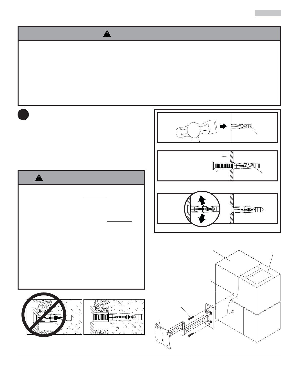
Installation to Solid Concrete and Cinder Block
WARNING
• When installing Peerless wall mounts on cinder block, verify that you have a minimum of 1-3/8" (35mm) of actual
concrete thickness in the hole to be used for the concrete anchors. Do not drill into mortar joints! Be sure to mount
in a solid part of the block, generally 1" (25mm) minimum from the side of the block. Cinder block must meet ASTM
C-90 specifi cations. It is suggested that a standard electric drill on slow setting is used to drill the hole instead of a
hammer drill to avoid breaking out the back of the hole when entering a void or cavity.
• Concrete must be 2000 psi density minimum. Lighter density concrete may not hold concrete anchor.
• Make sure that the wall will safely support four times the combined load of the equipment and all attached hardware
and components.
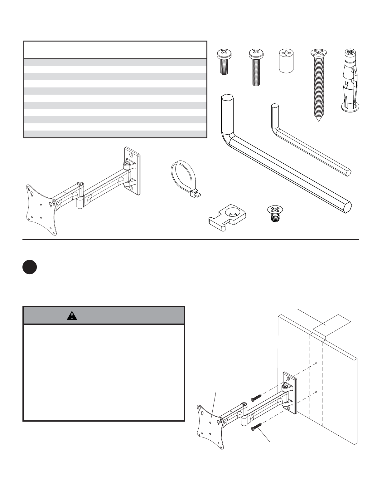
Level and use wall plate as template to mark
1
center of holes. Drill two 5/16" (8mm) dia. holes
to a minimum depth of 2-1/2" (64mm). Insert
anchors (F) in holes fl ush with wall. Place wall
arm assembly (AA) over anchor and secure with
wood screws (D). Make sure wall arm is level, and
tighten all fasteners.
WARNING
• Tighten screws so that wall plate is fi rmly attached,
but do not overtighten. Overtightening can damage
screws, greatly reducing their holding power.
• Never tighten in excess of 80 in. • lb (9 N.M.).
• Always attach concrete expansion anchors directly to
load-be aring concrete.
• Never attach concrete expansion anchors to concrete
covered with plaster, drywall, or other fi nishing
material. If mounting to concrete surfaces covered
with a fi nishing surface is unavoidable (not evaluated
by UL), the fi nishing surface must be counterbored
as shown below. Be sure concrete anchors do not
pull away from concrete when tightening screws. If
plaster/drywall is thicker than 5/8" (16mm), custom
fasteners must be supplied by installer (not evaluated
by UL).
1
concrete
surface
F
Drill holes and insert anchors (F).
2
Place wall plate (AA) over anchors (F) and secure with screws (D).
3
Tighten all fasteners.
SOLID CONCRETE
AA
D
F
CINDER
BLOCK
AA
CUTAWAY VIEW
plaster/
dry wall
INCORRECT CORRECT
concrete
AA
plaster/
dry wall
concrete
4 of 20
F
D
AA
ISSUED: 06-18-07 SHEET #: 095-9269-6 02-15-12
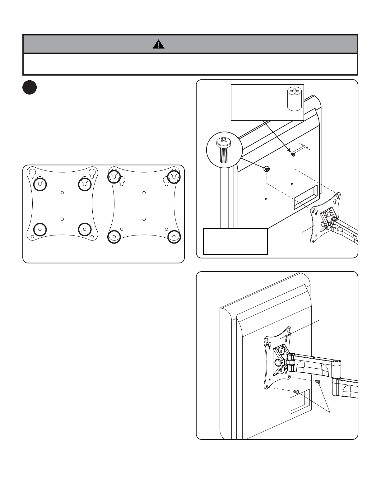
Attaching Front Plate to Display Using VESA 75 or 100mm Mounting Patterns
WARNING
• If screws don't get three complete turns in the display inserts or if screws bottom out and bracket is still not tightly
secured, damage may occur to display or product may fail.
Insert two M4 x 12mm screws (A) into top two
2
holes of display, leaving approximately 1/4" (6mm)
of exposed thread. Hook screws onto keyslots of
adapter plate as indicated in fi gures 2.1 and 2.2.
*NOTE: If hole pattern is in a pocket, insert two
M4 x 20mm screws (B) with two retaining spacers
(C) into top two holes of display as indicated right.
Insert two M4 screws (A or B) through bottom
holes of adapter plate as shown in fi gure 2.3.
fi g. 2.1
FOR VESA® 75
MOUNTING PATTERN:
FOR VESA 100
MOUNTING PATTERN:
fi g. 2.2
*For displays with
a hole pattern in a
pocket, spacers (C) go
between adapter plate
and display.
A
Display may appear
slightly different
than illustrated
C
1/4"
ADAPTER
PLATE
5 of 20
fi g. 2.3
ADAPTER
PLATE
A,B
ISSUED: 06-18-07 SHEET #: 095-9269-6 02-15-12
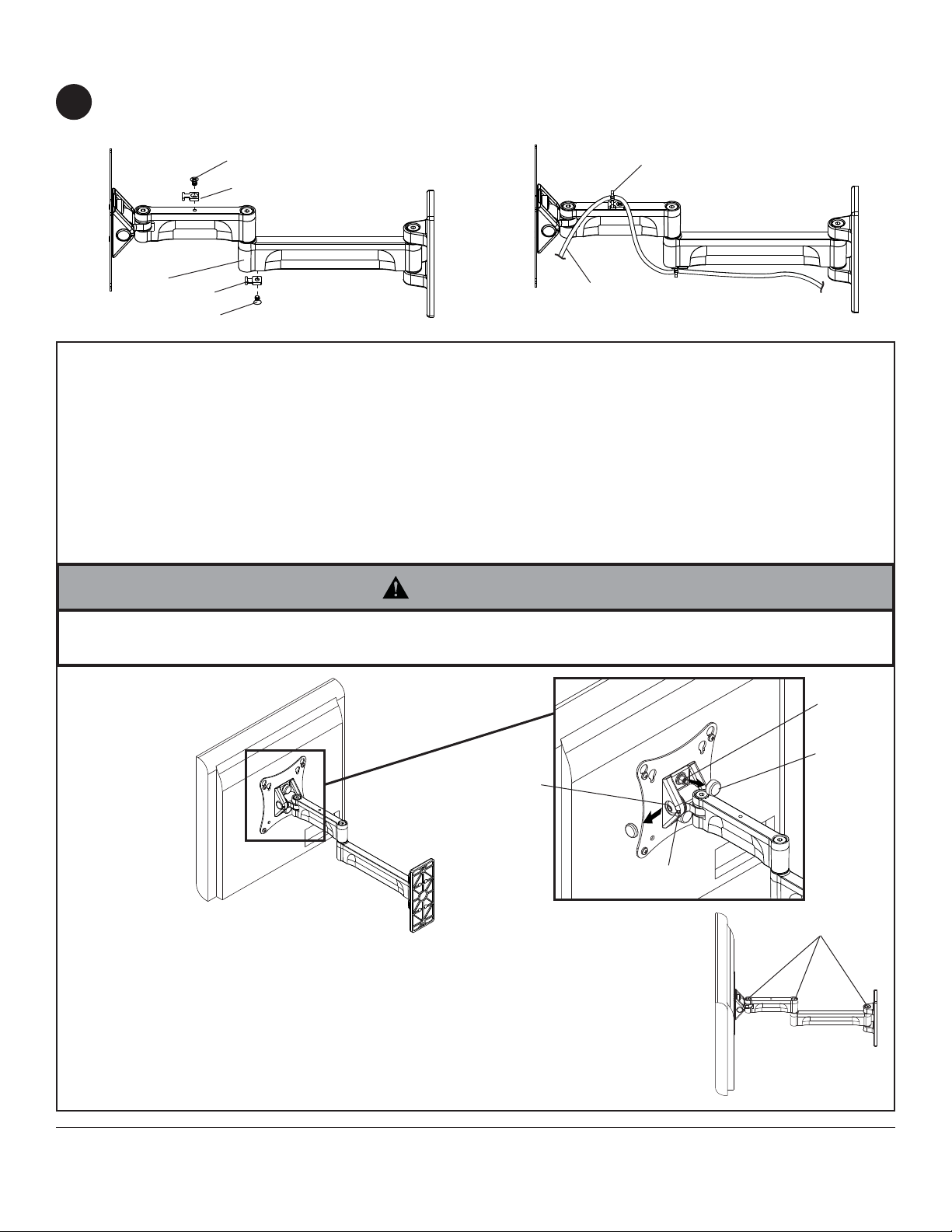
Cord Management
Attach cable tie anchor (H) to top or bottom of wall arm (AA) using screw (J) as shown in fi gure 3.1. Secure
3
cables to wall arm (AA) using cable tie (G) as shown in fi gure 3.2.
J
G
H
AA
H
J
fi g. 3.1
DISPLAY
CABLES
fi g. 3.2
OPTIONAL
NOTE: Adjustment points (socket screws) are factory torqued for optimal performance. This factory torque setting is
recommended to prevent the display from slipping over time. If more or less tension is desired follow this optional
step. You may not achieve optimal torque value if factory torque settings are adjusted.
If more or less tension is desired in the tilt mechanism, do the following:
• To adjust tilt, insert a fl at head screw driver into slot and remove cap covering the socket screw. Tighten or loosen
socket screw no more than half a turn using 5mm allen wrench (E) as shown in detail 1.
• To adjust roll, remove snap caps covering the 10-32 nylock nuts as shown in detail 1. Loosen 10-32 nylock nuts half
a turn and adjust roll position. Retighten 10-32 nylock nuts after display is in desired roll position.
WARNING
• Do not loosen socket screws or nylock nuts to the point they become disengaged from the mount. Doing so may
cause the display to fall.
10-32
NYLOCK
NUT
SNAP CAP
SOCKET
SCREW
SLOT
DETAIL 1
If more or less tension is desired in the arm pivot points, do the following:
• To increase tension, turn socket screw clockwise with 3/16" allen wrench (I).
• To reduce tension, turn socket screw counter-clockwise with 3/16" allen
wrench (I). Do not turn more than half a turn.
SOCKET SCREWS
6 of 20
All other brand and product names are trademarks or registered trademarks of their respective owners.
ISSUED: 06-18-07 SHEET #: 095-9269-6 02-15-12
© 2012, Peerless Industries, Inc. All rights reserved.
Peerless Industries, Inc.
2300 White Oak Circle
Aurora, Il 60502
www.peerlessmounts.com

Instalación y ensamblaje:
Paramount ™ brazo articulado pared de 10" - 24" con pantalla
de montaje VESA 75 o 100 patrón.
Modelo: PA730, PA730-S
I
D
:
0
Máxima UL capacidad: 25 lb (11.34 kg)
2300 White Oak Circle • Aurora, Il 60502 • (800) 865-2112 • Fax: (800) 359-6500 • www.peerlessmounts.com
PUBLICADO: 06-18-07 HOJA #: 095-9269-6 02-15-12
2
6
7
0
8
0
1
0
0

Español
NOTA: Lea la hoja de instrucciones completa antes de comenzar la instalación y el ensamblaje.
ADVERTENCIA
• No comience a instalar su producto de Peerless hasta haber leído y entendido las instrucciones y las advertencias
contenidas en la Hoja de Instalación. Si tiene alguna pregunta acerca de cualquiera de las instrucciones o las
advertencias, por favor, llame a Servicio al Cliente de Peerless al 1-800-865-2112 si está en EE. UU. Si es un cliente
internacional, por favor, comuníquese con su distribuidor local.
• Este producto sólo debe ser instalado por una persona que tenga una buena aptitud mecánica, que tenga
experiencia en construcción básica de edifi cios y que entienda estas instrucciones en su totalidad.
• Asegúrese de que la superfi cie de apoyo sostendrá, con seguridad, la carga combinada del equipo y todos los
fi jadores y componentes.
• Nunca sobrepase la capacidad máxima de soportar carga aceptada por Underwriters Laboratories. Vea la página 7.
• Si va a instalar el producto en una pared con montantes de madera, asegúrese de que los tornillos de montaje estén
anclados en el centro de los montantes. Se recomienda utilizar un localizador de montantes de "borde a borde".
• Siempre cuente con la ayuda de un asistente o utilice un equipo mecánico de izar para levantar y colocar el equipo
con más seguridad.
• Apriete los tornillos con fi rmeza, pero no en exceso. Apretarlos en exceso puede dañar los artículos y puede
disminuir signifi cativamente su fuerza de fi jación.
• Este producto está diseñado para uso en interiores solamente. Utilizar este producto en exteriores podría causar
fallas del producto y lesiones a individuos.
• Este producto fue diseñado para ser instalado en paredes con la siguiente construcción solamente:
CONSTRUCCIÓN DE LA PARED ACCESORIOS NECESARIOS
• Montante de madera Incluido
• Viga de madera Incluido
• Concreto macizo Incluido
• Bloque de hormigón de escorias Incluido
• Ladrillo Comuníquese con un profesional califi cado (no evaluados por UL)
• ¿Otra superfi cie o no está seguro? Comuníquese con un profesional califi cado
Herramientas necesarias para el ensamblaje
• localizador de montantes (se recomienda uno de "borde a borde")
• destornillador phillips
• taladro
• broca de 5/16" (8mm) para paredes de concreto y de bloque de hormigón de escorias
• broca de 5/32" (4mm) para paredes con montantes de madera
• nivel
Contenido
Lista de piezas........................................................................................................................................................................9
Instalación en una pared con montante de madera ...............................................................................................................9
Instalación en una pared de concreto macizo o de bloques de hormigón de escorias ....................................................... 10
Fijación de la placa de montaje a pantallas con confi guraciones de montaje VESA 75 ó 100 ............................................11
Manejo de cables ................................................................................................................................................................ 12
8 de 20
PUBLICADO: 06-18-07 HOJA #: 095-9269-6 02-15-12

Antes de comenzar, asegúrese de que su producto contiene todas las piezas que se muestran.
Las piezas pueden verse un poco distintas a la ilustración.
Español
Lista de piezas
Descripción Cant.
AA armazón del brazo de pared 1 095-P1709 095-4709
A tornillos phillips M4 x 12 mm 4 504-9013 504-2013
B tornillos phillips M4 x 20 mm 4 504-9020 504-2014
C espaciador de retención 4 590-5005 590-5003
D tornillos para madera de 14 x 2-1/2" 2 520-1202 520-2165
E llave allen de 5 mm 1 560-9640 560-9640
F concrete anchors 2 590-0320 590-0320
F anclaje para concreto 2 590-0320 590-0320
G sujetacables 2 560-9711 560-2004
H anclaje del sujetacables 2 590-1290 590-1290
I llave allen de 3/16" 1 560-0071 560-0071
J tornillos phillips 8-32 x 1/4" 2 520-1622 520-2622
AA
PA730 PA730-S
o
de pieza
N.
N.° de pieza
G
E
H
CD FBA
I
J
Instalación en el montante de madera de una pared
Con un detector de montantes, localice y marque los bordes del montante de madera donde se montará este
1
producto. Se recomienda enfáticamente que se utilice un detector de "borde a borde". Use un nivel para trazar
una línea vertical a lo largo del centro del montante. Use la placa de pared como plantilla para marcar el centro
de los hoyos a lo largo de la línea vertical. Taladre dos hoyos de 5/32" (4mm) de diámetro y 2-1/2" (64mm) de
profundidad. Fije el montaje del gancho de pared (AA) a la pared con dos tornillos de cabeza plana para madera
#14 x 2-1/2" (D), según se muestra en la ilustración 1.1.
PARED CON MONTANTE
ADVERTENCIA
• Cerciórese de que la superfi cie de soporte apoye
con seguridad la carga combinada del equipo y todo
el hardware y componentes unidos.
• Ajuste los tornillos para que la placa de pared esté
adherida con fi rmeza pero no los apriete demasiado.
Al apretarlos demasiado, se pueden dañar y reducir
en gran medida su capacidad para agarrar.
• Nunca apriete en exceso de 80 plg. • lib. (9 N.M.).
• Asegúrese de que los tornillos de montaje
estén anclados del centro de los montantes. Se
recomienda enfáticamente que se utilice un detector
de "borde a borde".
DE MADERA
AA
Pase al paso 2.
9 de 20
D
PUBLICADO: 06-18-07 HOJA #: 095-9269-6 02-15-12
fi g. 1.1

Español
Instalación en una pared de concreto macizo o de
bloques de hormigón de escorias
ADVERTENCIA
• Cuando instale soportes de pared Peerless en bloques de hormigón de escorias, verifi que que tengan un mínimo de
1-3/8" (35mm) de superfi cie efectiva de concreto en el agujero que va a utilizar para los anclajes de concreto. ¡No
perfore en las juntas de mortero! Asegúrese de instalar el soporte en una parte sólida del bloque, generalmente a un
mínimo de 1" (25mm) del costado del bloque. El bloque de hormigón de escorias debe ser de conformidad con las
especifi caciones C-90 de ASTM. Se sugiere taladrar el agujero con un taladro eléctrico normal en velocidad lenta en
vez de un taladro percutor para evitar romper la parte trasera del agujero al entrar en un espacio o cavidad.
• El concreto debe tener una densidad mínima de 2000 psi. Un concreto menos denso podría no ser capaz de sujetar
el anclaje para concreto.
• El instalador debe verifi car que la superfi cie de apoyo sea capaz de soportar fi rmemente la carga combinada del
equipo y todos los herrajes y componentes.
Nivele y use la placa de pared como plantilla
1
para marcar el centro de los hoyos. Taladre
dos hoyos de 5/16" (8mm) de diámetro a una
profundidad mínima de 2-1/2" (64mm). Inserte las
expansiones (F) en los hoyos a ras de la pared.
Coloque el montaje del gancho de pared (AA)
sobre la expansión y fíjelo con tornillos de madera
(D). Asegúrese de que el gancho de pared esté
nivelado y ajuste todos los tornillos.
1
Perfore los agujeros y después inserte los anclajes (F).
2
AA
superfi cie de
concreto
F
ADVERTENCIA
• Apriete los tornillos de tal modo que la placa de apoyo
quede fi rmemente sujeta, pero no los apriete en
exceso. El apriete excesivo puede dañar los tornillos,
reduciendo enormemente su fuerza de fi jación.
• Nunca apriete más de 80 pulg-lb (9 N•m).
• Siempre fi je los anclajes de expansión directamente
al concreto que soporta carga.
• Nunca fi je los anclajes de expansión a una pared
de concreto recubierta con yeso, tabiques de yesocartón u otro material de acabado. Si el montaje a
superfi cies de concreto recubiertas con una superfi cie
de acabado es inevitable (no evaluados por UL), será
necesario escariar el acabado, como se muestra más
abajo. Asegúrese de que los anclajes de concreto
no se alejen del concreto al apretar los tornillos. Si el
grosor de la pared de yeso/tabique de yeso-cartón
es mayor que 5/8" (16mm), el instalador deberá
suministrar fi jaciones especiales (no evaluados por
UL).
INCORRECTO
concreto
AAAA
CORRECTO
concreto
D
Coloque la placa (AA) sobre los anclajes (F) y fíjela con
los tornillos (D).
3
Apriete todas las fi jaciones.
CONCRETO MACIZO
F
D
AA
F
BLOQUE DE
HORMIGÓN DE
ESCORIAS
VISTA EN CORTE
yeso / tabique de yeso-cartón
10 de 20
PUBLICADO: 06-18-07 HOJA #: 095-9269-6 02-15-12

Español
Fijación de la placa de montaje a pantallas con confi guraciones de montaje
VESA® 75 ó 100
ADVERTENCIA
• Si los tornillos no pueden atornillarse tres vueltas completas en los insertos de la pantalla, o si los tornillos topan
fondo y la escuadra todavía no está fi rmemente sujeta, se podría dañar la pantalla o causar la falla del producto.
2
fi g. 2.1
Coloque dos tornillos M4 x 12mm (A) en los
dos agujeros superiores de la pantalla; deje
aproximadamente 1/4" (6mm) de la rosca
expuesta. Enganche los tornillos en las ranuras de
la placa adaptadora como se indica en las fi guras
2.1 y 2.2.
*NOTA: Si la confi guración de agujeros está en
una cavidad, coloque dos tornillos M4 x 20mm (B)
con dos espaciadores de retención (C) en los dos
agujeros superiores como se indica "correcto".
Coloque dos tornillos M4 (A o B) a través del
agujeros inferior de la placa adaptadora como se
muestra en la fi gura 2.3.
fi g. 2.2
*En el caso de las pantallas
que tienen la confi guración de
agujeros en una cavidad, los
espaciadores (C) van entre la
placa adaptadora y la pantalla.
A
La pantalla puede
verse un poco diferente
a la ilustración.
C
1/4"
PLACA
ADAPTADORA
EN EL CASO DE LA
CONFIGURACIÓN DE
MONTAJE DE VESA® 75
EN EL CASO DE LA
CONFIGURACIÓN DE
MONTAJE DE VESA® 100
11 de 20
fi g. 2.3
PLACA
ADAPTADORA
A,B
PUBLICADO: 06-18-07 HOJA #: 095-9269-6 02-15-12
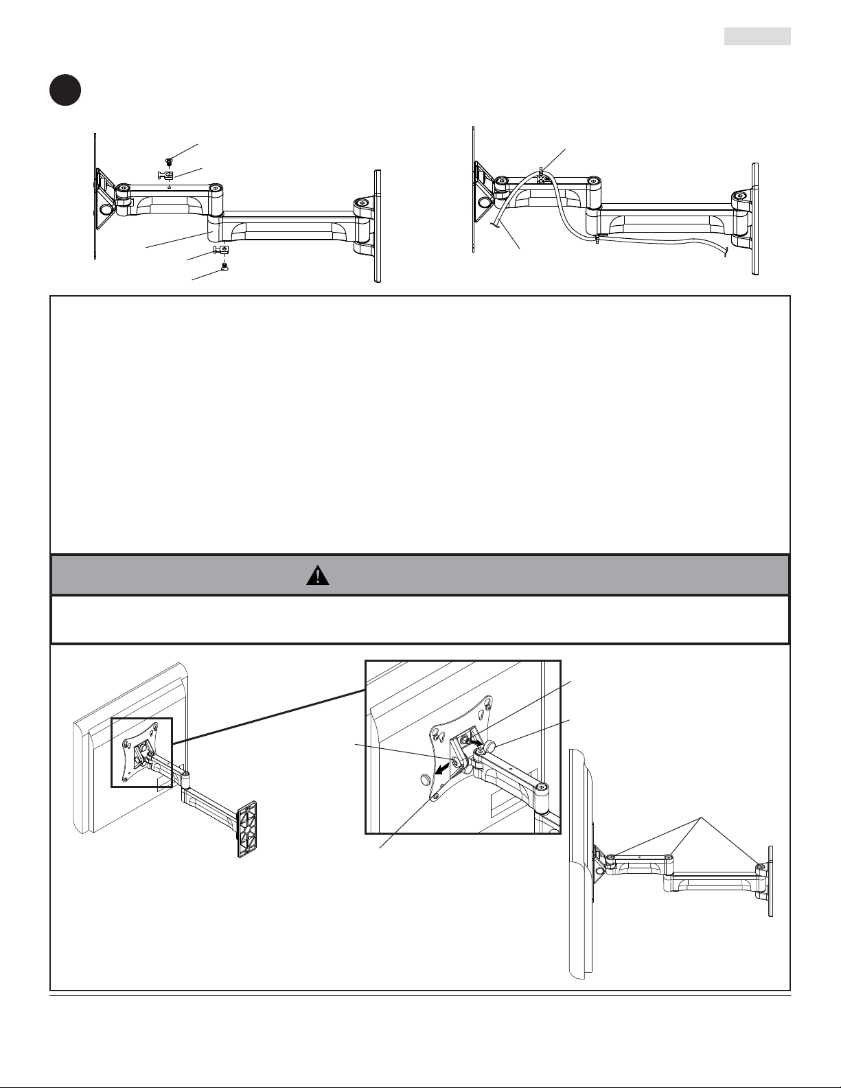
Manejo de cables
Fije el anclaje del sujetacables (H) a la parte superior o inferior del brazo de pared (AA) utilizando un tornillo (J),
3
como se muestra en la fi gura 3.1. Fije los cables al brazo de pared (AA) utilizando el sujetacables (G), como se
muestra en la fi gura 3.2.
Español
J
G
H
AA
H
J
fi g. 3.1
CABLES DE
LA PANTALLA
fi g. 3.2
OPCIONAL
NOTA: Los puntos de ajuste (tornillos de cabeza hueca) se fi jan y se aprietan en la fábrica para un
funcionamiento óptimo. Se recomienda el ajuste de torsión de fábrica para evitar que la pantalla se deslice con
el tiempo. Si desea darles más o menos tensión, siga este paso opcional. Es posible que no logre darles el par
tosor de fábrica si afl oja los puntos de ajuste.
Si desea más o menos tensión en el mecanismo de inclinación, haga lo siguiente:
• Para ajustar la inclinación, inserte un destornillador para tornillos de cabeza plana en la ranura y quite la
cubierta que tapa el tornillo de cabeza hueca. No apriete ni afl oje el tornillo de cabeza hueca más de media
vuelta; utilice una llave allen (E) de 5mm, como se muestra en el detalle 1.
• Para ajustar la rotación, quite las tapas a presión de las tuercas Nylock 10-32, como se muestra en el detalle
1. Afl oje las tuercas Nylock 10-32 media vuelta y ajuste la posición de rotación. Vuelva a apretar las tuercas
Nylock 10-32 cuando la pantalla esté en la posición de rotación deseada.
ADVERTENCIA
• No afl oje los tornillos de cabeza hueca ni las tuercas Nylock hasta el punto en que se salgan del soporte. Hacerlo
podría causar que se caiga la pantalla.
DETALLE 1
TORNILLO DE
CABEZA HUECA
RANURA
Si desea más o menos tensión en los puntos giradores del brazo,
haga lo siguiente:
• Para aumentar la tensión, gire el tornillo de cabeza hueca en el sentido
del movimiento de las manecillas del reloj con la llave allen de 3/16" (I).
• Para reducir la tensión, gire el tornillo de cabeza hueca en el sentido
contrario al movimiento de las manecillas del reloj con la llave allen (I).
No lo gire más de media vuelta.
TUERCA NYLOCK DEL
NÚMERO 10-32
TAPA DE PRESIÓN
TORNILLO DE
CABEZA HUECA
12 de 20
Cualesquiera otras marcas y nombres de productos son marcas comerciales o registradas de sus respectivos dueños.
PUBLICADO: 06-18-07 HOJA #: 095-9269-6 02-15-12
© 2012, Peerless Industries, Inc. Todos los derechos reservados.
Peerless Industries, Inc.
2300 White Oak Circle
Aurora, Il 60502
www.peerlessmounts.com

Installation et assemblage:
Support mural articulé Paramount™ pour écrans de
10 - 24 po compatibles à la norme de montage VESA 75 ou 100
Modèle: PA730, PA730-S
I
D
2
:
6
0
7
0
8
0
1
0
0
Capacité de charge UL maximale: 25 lb (11.34 kg)
2300 White Oak Circle • Aurora, Il 60502 • (800) 865-2112 • Fax: (800) 359-6500 • www.peerlessmounts.com
PUBLIÉ LE: 06-18-07 FEUILLE no: 095-9269-6 02-15-12
Français
REMARQUE: lisez entièrement la fi che d’instructions avant de commencer l’installation et l’assemblage.
AVERTISSEMENT
• Ne commencez pas à installer votre produit Peerless avant d’avoir lu et assimilé les instructions et les avertissements
contenus dans cette fi che d’installation. Pour toute question concernant les instructions ou les avertissements,
veuillez appeler le service à la clientèle de Peerless au 1-800-865-2112; tous les clients internationaux sont priés de
contacter leur distributeur local.
• Ce produit doit être installé uniquement par quelqu’un possédant une bonne aptitude à la mécanique, une expérience
de la construction immobilière et ayant bien compris ces instructions.
• Assurez-vous que la surface de support puisse soutenir sans danger la charge totale de l’équipement ainsi que des
pièces et composants qui y sont attachés.
• Ne dépassez jamais la capacité de charge maximum établie par l’UL. Reportez-vous à la page 13.
• Lors d’une installation sur un mur à montants en bois, assurez-vous que les vis de montage sont ancrées au centre
des montants. L’utilisation d’un localisateur de montants " bord à bord " est fortement recommandée.
• Pour lever et positionner l’équipement en toute sécurité, faites-vous toujours aider par une autre personne ou utilisez
un dispositif de levage mécanique.
• Serrez fermement les vis, mais sans excès. Un serrage excessif peut endommager les composants et en réduire
considérablement la capacité de support.
• Ce produit est conçu uniquement pour un usage intérieur. L’utilisation de ce produit à l’extérieur peut causer une
défaillance du produit et des blessures corporelles.
• Ce produit a été conçu uniquement pour une installation sur les types de murs ci-dessous :
TYPE DE MUR PIÈCES DE FIXATION REQUISES
• Montant en bois Incluses
• Poutre en bois Incluses
• Béton plein Incluses
• Bloc de béton de mâchefer Incluses
• Brique Contacter un professionnel qualifi é (non évalué UL)
• Autre, ou vous n’êtes pas sûr ? Contacter un professionnel qualifi é
Outils nécessaires au montage
• localisateur de montants (un localisateur de montants " bord à bord " est recommandé)
• tournevis phillips
• perceuse
• foret de 5/16 po (8mm) pour les murs à block de béton
• foret de 5/32 po (4mm) pour les murs à montants en bois
• niveau
Table des matières
Liste des pièzas ....................................................................................................................................................................15
Installation sur un mur à montant en bois.............................................................................................................................15
Installation sur du béton plein ou un bloc de béton de mâchefer .........................................................................................16
Fixation de la plaque de montage à un écran compatible à la norme de montage VESA 75 ou 100 ..................................17
Organisation des câbles .......................................................................................................................................................18
14 sur 20
PUBLIÉ LE: 06-18-07 FEUILLE no: 095-9269-6 02-15-12

Avant de commencer, veillez à ce que toutes les pièces énumérées soient incluses.
o
Les pièces peuvent différer légèrement de l’illustration.
Français
Liste des pièces
Description Qté Pièce no° Pièce no°
AA bras de montage mural 1 095-P1709 095-4709
A vis Phillips M4 x 12 mm 4 504-9013 504-2013
B vis Phillips M4 x 20 mm 4 504-9020 504-2014
C entretoise 4 590-5005 590-5003
vis à bois n
D
E clè hexagonale 5 mm 1 560-9640 560-9640
F concrete anchors 2 590-0320 590-0320
F chevilles d'ancrage pur béton 2 590-0320 590-0320
G attaches de câble 2 560-9711 560-2004
H fixez l’ancrage 2 590-1290 590-1290
I clè hexagonale 3/16 po 1 560-0071 560-0071
J vis Phillips 8-32 x 1/4 po 2 520-1622 520-2622
14 x 2-1/2 po
AA
PA730 PA730-S
2 520-1202 520-2165
G
E
H
CD FBA
I
J
Installation sur un mur à colombages de bois
À l’aide d’un localisateur de colombages, trouvez et marquez les bords du colombage sur lequel sera monté ce
1
dispositif. L’emploi d’un localisateur des poteaux d’ossature " bord à bord " est fortement recommandé. À l’aide
d’un niveau, tracez une ligne verticale le long du centre du colombage. Servez-vous de la plaque murale comme
d’un gabarit pour marquer le centre des trous le long de cette ligne verticale. Percez deux trous de 4mm (5/32 po)
de diamètre et de 64mm (2-1/2 po) de profondeur dans le centre des colombages. Attachez le bras mural (AA)
au mur à l’aide de deux vis pour bois cruciformes à tête plate no 14 x 64mm (2-1/2 po) (D) tel qu’illustré à la fi gure
1.1.
AVERTISSEMENT
• L’installateur doit s’assurer que la surface de support
pourra soutenir sans danger le poids combiné de
l’appareil, de toute sa visserie et de tous ses composants.
• Serrez les vis jusqu’à ce que la plaque murale soit
fermement fi xée, mais ne les serrez pas trop. Un
serrage excessif pourrait endommager les vis, ce qui
réduirait sensiblement leur capacité de support.
• Ne serrez jamais à un couple supérieur à 80 po/lb
(9 N.m).
• Assurez-vous que les vis de montage sont bien
fi xées au centre des poteaux d’ossature. L’emploi
d’un localisateur des poteaux d’ossature " bord à
bord " est fortement recommandé.
AA
PLAQUE MURALE
D
Passez à l’étape 2.
fi g. 1.1
15 sur 20
PUBLIÉ LE: 06-18-07 FEUILLE no: 095-9269-6 02-15-12
Français
Installation sur du béton plein ou un bloc de béton de mâchefer
AVERTISSEMENT
• Si vous installez des montures murales Peerless sur un bloc de béton de mâchefer, vérifi ez que vous disposez d’une
épaisseur de béton d’au moins 35mm (1 3/8 po) dans le trou destiné aux ancrages de béton. Ne percez pas dans
les joints de mortier ! Veillez à effectuer le montage dans une partie pleine du bloc, généralement à au moins 25mm
(1 po) du côté du bloc. Le bloc de béton de mâchefer doit être conforme aux spécifi cations de l’ASTM C-90. Pour
percer le trou, il est conseillé d’utiliser une perceuse électrique standard sur un réglage bas au lieu d’un marteau
perforateur, afi n d’éviter de briser la partie arrière du trou lorsque vous pénétrez un vide ou une cavité.
• Le béton doit avoir une densité minimum de 2 000 psi. Un béton de densité moindre risquerait de ne pas retenir un
ancrage de béton.
• Assurez-vous que la surface de support pourra soutenir sans danger la charge combinée de l’équipement, de toute
sa visserie et de tous ses composants.
Assurez-vous que la plaque murale est bien de
1
niveau et servez-vous-en comme d’un gabarit pour
marquer le centre des trous. Percez deux trous
de 8mm (5/16 po) de diamètre sur une profondeur
minimum de 64mm (2-1/2 po). Insérez les
chevilles (F) dans les trous à ras du mur. Placez le
bras mural (AA) sur la cheville et fi xez-le à l’aide
des vis à bois (D). Assurez-vous que le bras mural
est bien de niveau, et serrez tous les organes
d’assemblage.
1
Percez des trous et insérez les ancrages (F).
2
AA
surface en
béton
F
AVERTISSEMENT
• Serrez les vis de manière que la plaque murale
soit fermement fi xée, mais sans excès. Un serrage
excessif peut endommager les vis et en réduire
considérablement le pouvoir de maintien.
• Ne serrez jamais à plus de 9 Nm (80 po-lb).
• Fixez toujours des ancrages de béton directement sur
du béton porteur.
• Ne fi xez jamais d’ancrages sur du béton recouvert de
plâtre, une cloison sèche ou autre matériau de fi nition.
Si vous ne pouvez pas éviter d’effectuer le montage
sur du béton recouvert d’une surface de fi nition (non
évalué UL), celle-ci doit être chambrée, comme indiqué
cidessous. Assurez-vous que les ancrages de béton ne
se séparent pas du béton lorsque vous serrez les vis.
Si l’épaisseur du plâtre / de la cloison sèche dépasse
16mm (5/8 po), des fi xations adaptées devront être
fournies par l’installateur (non évalué UL).
INCORRECT CORRECT
AA
plâtre /
VUE EN COUPE
cloison sèche
béton
AA
plâtre /
cloison sèche
béton
D
Placez la plaque (AA) sur les ancrages (F) et fi xez avec
des vis (D).
3
Serrez toutes les fi xations.
BÉTON PLEIN
F
D
AA
F
BLOC DE
BÉTON DE
MÂCHEFER
16 sur 20
PUBLIÉ LE: 06-18-07 FEUILLE no: 095-9269-6 02-15-12

Français
Fixation de la plaque de montage à un écran compatible à la norme de
montage VESA 75 ou 100
AVERTISSEMENT
• Si les vis ne sont pas enfoncées de trois tours complets dans les inserts ou si elles sont serrées au maximum sans
parvenir à fi xer solidement le support, l’écran peut être abîmé ou le produit détérioré.
2
fi g. 2.1
Insérez deux vis M4 x 12mm (A) dans les trous
supérieurs du moniteur, en laissant environ 6mm
(1/4 po) de fi letage exposé. Accrochez les vis
aux boutonnières de la plaque d’adaptation tel
qu’indiqué sur les fi gures 2.1 et 2.2.
*REMARQUE : Si les trous sont percés très près
les uns des autres, insérez deux vis M4 x 20mm
(B) et deux entretoises de retenue (C) dans les
deux trous supérieurs du moniteur, tel qu’indiqué
ci-contre.
Insérez deux vis M4 (A ou B) dans les trous
inférieurs de la plaque d’adaptation, tel qu’illustré
à la fi gure 2.3.
fi g. 2.2
* Dans le cas d’un moniteur dont
les trous sont percés très près
les uns des autres, mettez des
entretoises (C) entre la plaque
d’adaptation et le moniteur.
A
Certains écrans peuvent
être légèrement différents
de celui illustré ici.
C
1/4"
PLAQUE
D’ADAPTATION
POUR UNE
DISPOSITION DE
MONTAGE VESAMD 75
POUR UNE
DISPOSITION DE
MONTAGE VESAMD 100
17 sur 20
fi g. 2.3
PLAQUE
D’ADAPTATION
A,B
PUBLIÉ LE: 06-18-07 FEUILLE no: 095-9269-6 02-15-12

Organisation des câbles
Fixez l’ancrage (H) de l’attache de câble sur le haut ou le bas du bras mural (AA) à l’aide de vis (J), tel qu’illustré
3
à la fi gure 3.1. Attachez les câbles au support mural (AA) à l’aide de l’attache de câble (G), tel qu’illustré à la
fi gure 3.2.
Français
J
G
H
AA
H
J
fi g. 3.1
CÂBLES DE
L’ÉCRAN
fi g. 3.2
FACULTATIF
REMARQUE : Le couple de serrage des points de réglage (vis à tête creuse) est réglé en usine pour assurer une
performance optimale. Il est conseillé d’utiliser ce réglage d’usine pour empêcher l’écran de glisser au fi l du temps.
Si vous souhaitez augmenter ou diminuer la tension, veuillez suivre cette étape facultative. Vous risquez de ne pas
obtenir un serrage optimal si vous modifi ez les réglages d’usine.
Pour augmenter ou diminuer la tension du dispositif d’inclinaison, procédez comme suit :
• Pour régler l’inclinaison, insérez un tournevis plat dans la fente et retirez le capuchon recouvrant la vis à tête
creuse. Serrez ou desserrez la vis à tête creuse à un maximum d’un demi-tour à l’aide d’une clé hexagonale de
5mm (E) comme illustré dans le dessin de détail 1.
• Pour régler le pivotement latéral, retirez les capuchons à pression recouvrant les écrous Nylock 10-32 comme
illustré dans le dessin de détail 1. Desserrez les écrous Nylock 10-32 d’un demi-tour et réglez la position de
pivotement latéral. Resserrez les écrous Nylock 10-32 lorsque l’écran est dans la position de pivotement latéral
souhaitée.
AVERTISSEMENT
• Ne pas desserrer les vis à tête creuse ni les écrous Nylock au point où ils se détachent de l’assemblage. Cela
risquerait de faire tomber l’écran.
DÉTAIL 1
VIS À TÊTE CREUSE
FENTE
Pour augmenter ou diminuer la tension des points de pivotement
du bras, procédez comme suit :
• Pour augmenter la tension, tournez la vis à tête creuse dans le sens
des aiguilles d’une montre à l’aide d’une clé hexagonale de 3/16 po (I).
• Pour diminuer la tension, tournez la vis à tête creuse dans le sens
contraire des aiguilles d’une montre à l’aide de la clé hexagonale (I).
Ne tournez pas de plus d’un demi-tour.
18 sur 20
Tous les autres noms de marques et de produits sont des marques de commerce ou déposées de leurs propriétaires respectifs.
PUBLIÉ LE: 06-18-07 FEUILLE no: 095-9269-6 02-15-12
ÉCROU NYLOCK 10-32
CAPUCHON
ENCLIQUETABLE
VIS À TÊTE CREUSE
© 2012, Peerless Industries, Inc. Tous droits réservés.
Peerless Industries, Inc.
2300 White Oak Circle
www.peerlessmounts.com
Aurora, Il 60502

LIMITED FIVE-YEAR WARRANTY
Peerless Industries, Inc. ("Peerless") warrants to original end-users of Peerless® products will be free from defects in material and workmanship, under normal
use, for a period of fi ve years from the date of purchase by the original end-user (but in no case longer than six years after the date of the product’s manufacture).
In no event shall the duration of any implied warranty of merchantability or fi tness for a particular purpose be longer than the period of the applicable
express warranty set forth above. Some states do not allow limitations on how long an implied warranty lasts, so the above limitation may not apply to you.
This warranty does not cover damage caused by (a) service or repairs by the customer or a person who is not authorized for such service or repairs by Peerless,
(b) the failure to utilize proper packing when returning the product, (c) incorrect installation or the failure to follow Peerless’ instructions or warnings when installing,
In no event shall Peerless be liable for incidental or consequential damages or damages arising from the theft of any product, whether or not secured
by a security device which may be included with the Peerless® product. Some states do not allow the exclusion or limitation of incidental or consequential
This warranty is in lieu of all other warranties, expressed or implied, and is the sole remedy with respect to product defects. No dealer, distributor, installer or other
person is authorized to modify or extend this Limited Warranty or impose any obligation on Peerless in connection with the sale of any Peerless® product.
At its option, Peerless will repair or replace, or refund the purchase price of, any product which fails to conform with this warranty.
using or storing the product, or (d) misuse or accident, in transit or otherwise, including in cases of third party actions and force majeure.
damages, so the above limitation or exclusion may not apply to you.
This warranty gives specifi c legal rights, and you may also have other rights which vary from state to state.
www.peerlessmounts.com
© 2012 Peerless Industries, Inc.
Español
GARANTÍA LIMITADA DE CINCO AÑOS
Peerless Industries, Inc. (Peerless) les garantiza a los usuarios fi nales originales de los productos Peerless® que los productos Peerless® estarán libres de
defectos de materiales o de manufactura, en condiciones de uso normal, durante un periodo de cinco (5) años a partir de la fecha en la que el usuario fi nal
original compre cualquier producto (pero, en ningún caso, durante un periodo mayor de 6 años después de la fecha de manufactura del producto). Queda a la
La duración de toda garantía implícita de comerciabilidad o de idoneidad para un propósito en particular no sobrepasará en caso alguno el periodo
de vigencia de la garantía explícita correspondiente indica en lo anterior. Algunos Estados no permiten que se establezcan limitaciones en relación con el
Esta garantía no cubre daños causados por (a) trabajos de mantenimiento o de reparación hechos por el cliente o alguna persona que no esté autorizada por
Peerless para realizar dichos trabajos de mantenimiento o de reparación, (b) no empacar el producto como es debido si lo devuelve, (c) hacer una instalación
incorrecta o no seguir las instrucciones o las advertencias de Peerless al instalar, utilizar o guardar el producto o (d) el mal uso o los accidentes, en tránsito o en
Peerless no tendrá responsabilidad en ningún caso de daños y perjuicios incidentales o indirectos o de daños y perjuicios que surjan por el robo de
cualquier producto, ya sea que el mismo esté o no esté asegurado con un dispositivo de seguridad que se haya incluido con el producto de Peerless®.
Algunos Estados no permiten que se excluyan o se establezcan limitaciones en relación con los daños y perjuicios incidentales o indirectos, de manera que es
Esta garantía remplaza toda otra garantía, expresa o implícita, y es el único recurso en lo que respecta a los defectos del producto. Ningún concesionario,
distribuidor, instalador ni ninguna otra persona está autorizada a modifi car o extender esta Garantía Limitada ni a imponer obligación alguna a Peerless en
Esta garantía concede derechos específi cos creados por ley y es posible que usted, además, tenga otros derechos que varían de acuerdo con el Estado donde
discreción de Peerless, reparar, reemplazar o rembolsar el precio de compra de cualquier producto que no cumpla esta garantía.
periodo de duración de una garantía implícita, de manera que es posible que la limitación expuesta en lo anterior no sea pertinente a usted.
otras circunstancias, incluidos los casos relacionados con las acciones de terceros o una fuerza mayor.
posible que la limitación o la exclusión expuesta en lo anterior no sea pertinente a usted.
relación con la venta de cualquier producto de Peerless®.
se encuentre.
www.peerlessmounts.com
19 of 20
© 2012 Peerless Industries, Inc.
ISSUED: 06-18-07 SHEET #: 095-9269-6 02-15-12
Français
GARANTIE DE CINQ ANS
Peerless Industries, Inc. (" Peerless ") garantit aux utilisateurs fi naux d’origine des produits PeerlessMD que lesdits produits ne présenteront aucun défaut de
matériau ou de main-d’œuvre, dans la mesure où ils sont utilisés normalement, pendant une période de cinq ans à compter de la date d’achat par l’utilisateur fi nal
d’origine (mais en aucun cas plus de six ans après la date de fabrication du produit). Peerless, à sa discrétion, réparera ou remplacera tout produit non conforme
La durée de toute garantie implicite de qualité commerciale ou d'application à un usage particulier n'excédera en aucun cas la durée de la garantie
applicable expressément stipulée plus haut. Certains états ou provinces n’autorisent pas la limitation de la durée d’une garantie implicite, et la limitation ci-
Cette garantie ne couvre pas les dommages causés par (a) un entretien ou des réparations effectués par l'acheteur ou une personne non autorisée par Peerless
à effectuer un tel entretien ou de telles réparations, (b) un emballage inadéquat lors de l’expédition d’un produit retourné, (c) une installation incorrecte ou le non-
respect des instructions ou mises en garde de Peerless lors de l'installation, l'utilisation ou le rangement du produit, ou (d) une mauvaise utilisation ou un accident
Peerless ne peut en aucun cas être tenu responsable de quelque dommage accessoire ou indirect que ce soit ni de dommages résultant du vol
d’un quelconque produit, que celui-ci ait été ou non protégé par un dispositif de sécurité intégré à un produit PeerlessMD. Certains états ou provinces
n’autorisent pas l'exclusion ou la restriction des dommages accessoires ou indirects, et il est possible que les restrictions ou exclusions ci-dessus ne s'appliquent
Les dispositions de cette garantie remplacent toute autre garantie expresse ou implicite et constituent le seul recours possible en cas de défectuosité d’un
produit. Aucun marchand, distributeur, installateur ou autre personne n’est autorisé à modifi er ou étendre la portée de cette garantie limitée, ni à imposer quelque
Cette garantie offre des droits juridiques particuliers auxquels peuvent s’ajouter d’autres droits, susceptibles de varier d’une province ou d’un état à l’autre.
survenu lors d’un transport ou autrement, y compris l'intervention de tiers et les cas de force majeure.
obligation ce que soit à Peerless en ce qui concerne la vente de tout produit PeerlessMD.
aux termes de cette garantie, ou en remboursera le prix d’achat.
dessus peut donc ne pas vous être applicable.
pas à votre cas.
www.peerlessmounts.com
© 2012 Peerless Industries, Inc.
20 of 20
ISSUED: 06-18-07 SHEET #: 095-9269-6 02-15-12
 Loading...