

Page 1
Installation and Assembly - Multi-Channel Speaker
Accessory
Models: MSA-301,
MSA-301S
IMPORTANT! Read entire instruction sheet before you start inst allation and assembly .
NOTE: For use with FS-3200 C and FS-3200 LR speakers only
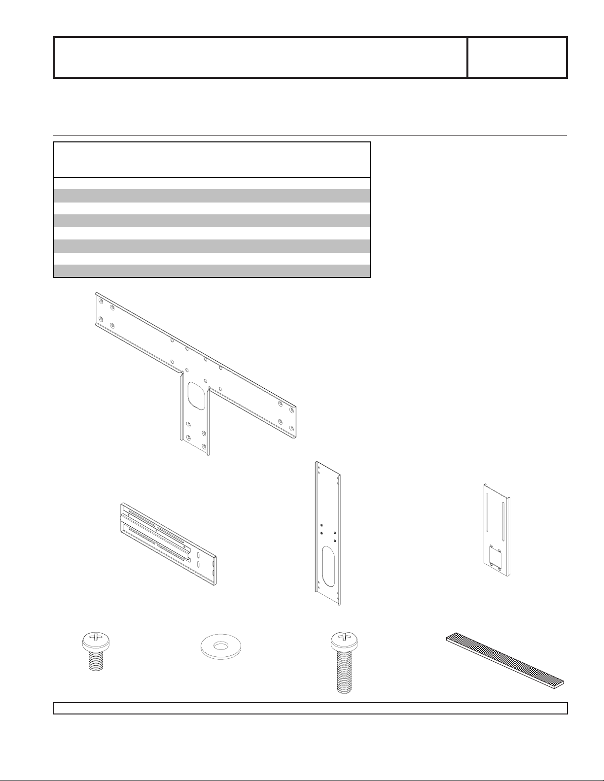
Parts Li st
De scrip tio n Qty. Part # Par t #
cros s support 1 087-1051 087-4051
A
side ext ens i on 2 087-1054 087-4054
B
speak er bracket 3 087-1057 087-4057
C
ext ens i on brac k et bottom 1 087-1050 087-4050
D
M5 x 10 m m phil l ips s crew 24 520-1233 520-1233
E
#10 SAE flat washer 12 540-9400 540-9400
F
M5 x 20 m m phil l ips s crew 12 510-1208 510-1208
G
adhesive velc ro 3 600-1018 600-1018
H
Note: some parts may not appear exactly as illustrated.
MSA-301 MSA-301S
A
MAXIMUM LOAD CAPACITY :
50 lb (22.68 kg)
B
D
C
E
Visit the Peerless Web Site at www.peerlessmounts.com For customer care call 1-800-865-2112 or 708-865-8870.
F
G
1 of 3
H
ISSUED: 02-09-07 SHEET #: 087-9014-1
Page 2
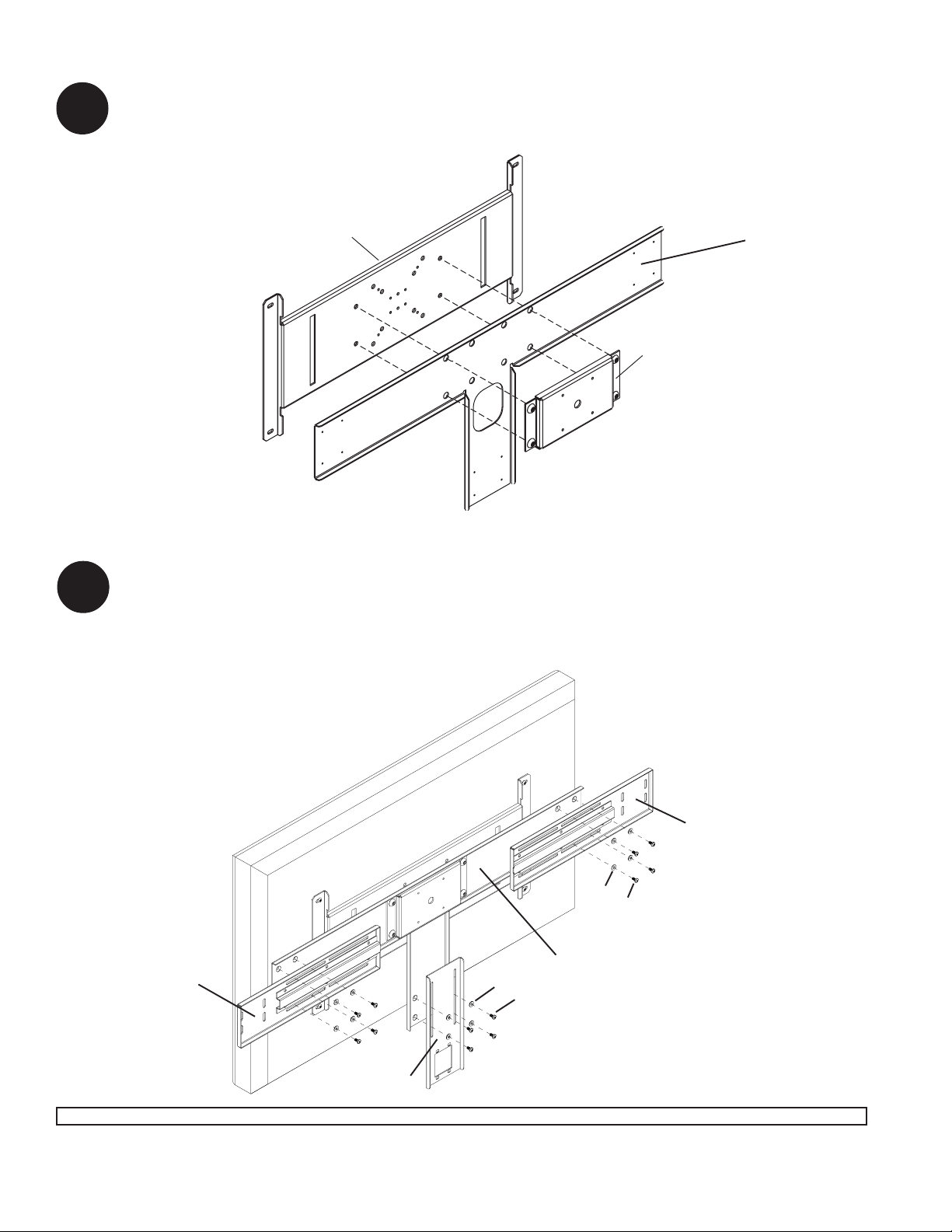
Installation to adapter plate
Loosen screws on plasma adapter. Then place cross support bracket (A) between plasma adapter and mount.
1
Tighten screws through cross support bracket to plasma adapter securely. Refer to adapter plate instructions for
installation of screen.
Note: some parts may not
appear exactly as illustrated.
PLASMA ADAPTER
A
MOUNT
Installation of Extension Brackets
Position side extension brackets (B) on both sides of cross support bracket (A) and align hole slots to allow for
desired position of left and right speakers. Loosely attach with eight sets of M5 x 10mm screws and flat washers (E, F).
2
Do not fully tighten screws to allow for position adjustments when attaching left and right speakers.
Position bottom extension bracket (D) on lower arm of cross support bracket (A), then attach with four sets of M5 x
10mm screws and flat washers (E, F). Do not fully tighten screws to allow for position adjustments when attaching
center speaker.
B
F
E
A
F
B
E
D
2 of 3
Visit the Peerless Web Site at www.peerlessmounts.com For customer care call 1-800-865-2112 or 708-865-8870.
ISSUED: 02-09-07 SHEET #: 087-9014-1
Page 3

Installation of Speakers
Position speaker brackets (C) to speakers using correct hole pattern as shown below and attach using twelve
M5 x 20mm screws (G).
3
RIGHT
SPEAKER
C
G
LEFT
SPEAKER
CENTER
SPEAKER
C
4
C
G
G
Attach speaker brackets (C) to side extension brackets (B) and extension bottom bracket (D) using twelve M5 x 10mm
screws (E). Position speakers to desired location and fully tighten fasteners connecting side extension brackets (B)
and extension bottom bracket (D) to cross support bracket (A).
Note: If positioning speakers against screen, additional support can be achieved using adhesive velcro strips (H).
Place adhesive velcro strips (H) on sides and bottom of screen and firmly press speakers against velcro before
securing side and bottom extension brackets (B, D).
C
A
E
H
B
C
H
D
B
C
3 of 3
Visit the Peerless Web Site at www.peerlessmounts.com For customer care call 1-800-865-2112 or 708-865-8870.
E
ISSUED: 02-09-07 SHEET #: 087-9014-1
All other brand and product names are trademarks or registered trademarks of their respective owners.
© 2007, Peerless Industries, Inc. All rights reserved.
 Loading...