

Page 1
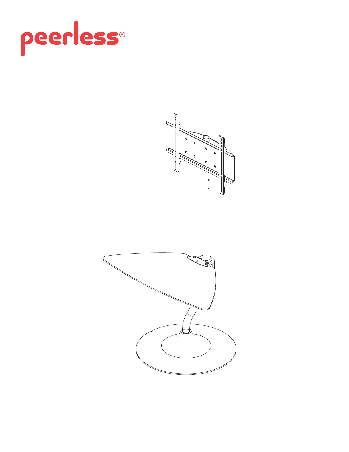
Installation and Assembly: 32" - 46" Flat Panel TV Stand
Model: FPZ-646
1 of 33
Max Load Capacity:
100 lb (45 kg) screen
25 lb (11 kg) per shelf
ISSUED: 1-25-11 SHEET #: 125-9150-7 09-28-12
Page 2
NOTE: Read entire instruction sheet before you start installation and assembly.
WARNING
• Do not begin to install your Peerless product until you have read and understood the instructions and warnings
contained in this Installation Sheet. If you have any questions regarding any of the instructions or warnings, for US
customers please call Peerless customer care at 1-800-865-2112, for all international customers, please contact
your local distributor.
• This product should only be installed by someone of good mechanical aptitude, and fully understands
these instructions.
• Never exceed the Maximum Load Capacity on page 1.
• Always use an assistant or mechanical lifting equipment to safely lift and position equipment.
• Tighten screws fi rmly, but do not overtighten. Overtightening can damage the items, greatly reducing their holding
power.
• The stand is not affi xed or secured to the fl oor, and may therefore tip over and/or fall if screen and/or stand is
shaken or hit. Always monitor children and do not let children play alone around stand as they could get hurt by a
falling screen. Not recommended for use in areas with heavy traffi c.
Tools Needed for Assembly
• level
• phillips screwdriver
Table of Contents
Parts List............................................................................................................................................................................ 3, 4
Assembling stand ...................................................................................................................................................................5
Attaching Universal Adapter Plate or Dedicated Adapter Plate ..............................................................................................6
Installing Adapter Brackets ....................................................................................................................................................8
Cord Management ................................................................................................................................................................11
2 of 33
ISSUED: 1-25-11 SHEET #: 125-9150-7 09-28-12
Page 3
A
V
Y
A
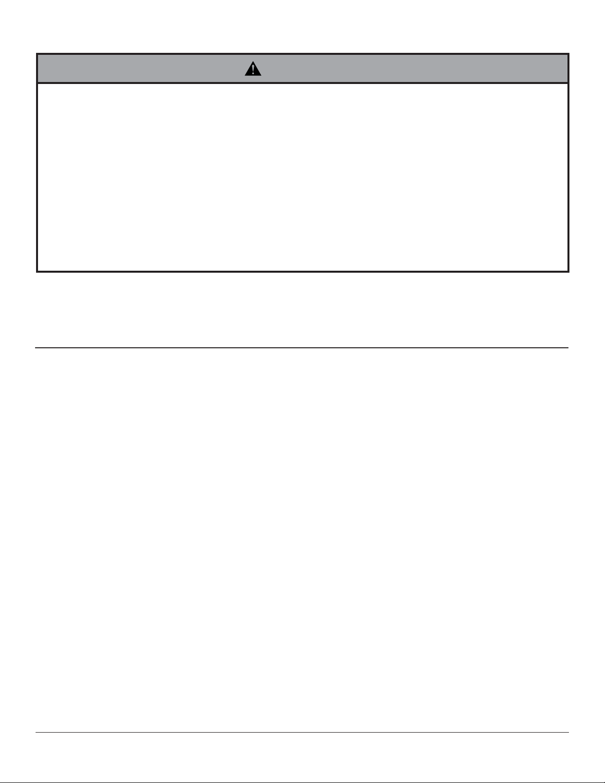
Parts List
Description
adapter plate
B 1 104-P1075
vertival tube
C 1 201-P1159
shelf clamp bracket
D 1 104-P1072
shelf support bracket
E adapter bracket 2 201-P1512
F top cover 1 590-P1340
G bottom cover 1 590-P1341
H support base 1 590-1039
I shelf support 1 104-P1073
J button bumper 9 590-1209
K 1/4-20 x 20 mm decorative screw 2 520-2326
L 5/16-18 x 2" socket screw 2 520-1116
M 5/16 nut 2 530-9306
N M10 x 15 mm socket screw 4 520-9262
O 6 mm allen wrench 1 560-9716
P 4 mm allen wrench 1 560-9646
Q adapter support plate 1 104-P1074
R M5 x 55 mm socket pin screw 1 520-1302
S M5 nut 1 530-9409
T 1/4-20 x 1.75" carriage bolt 2 560-1764
U 1/4-20 nut 2 530-9302
M5 x 10 mm socket pin screw 4 520-1063
W glass shelf 1 590-0208
X cable tie 5 560-9711
18" mesh sleeve 2 600-1014
Z 3/16" allen wrench 1 560-0071
A
plastic bushing 1 590-1378
Qty. Part #
1 201-P1016
C
D
A
F
B
E
G
S
K
L
H
MN
R
O
I
J
P Q
W
Z
T
UV
Y
X
AA
3 of 33
ISSUED: 1-25-11 SHEET #: 125-9150-7 09-28-12
Page 4
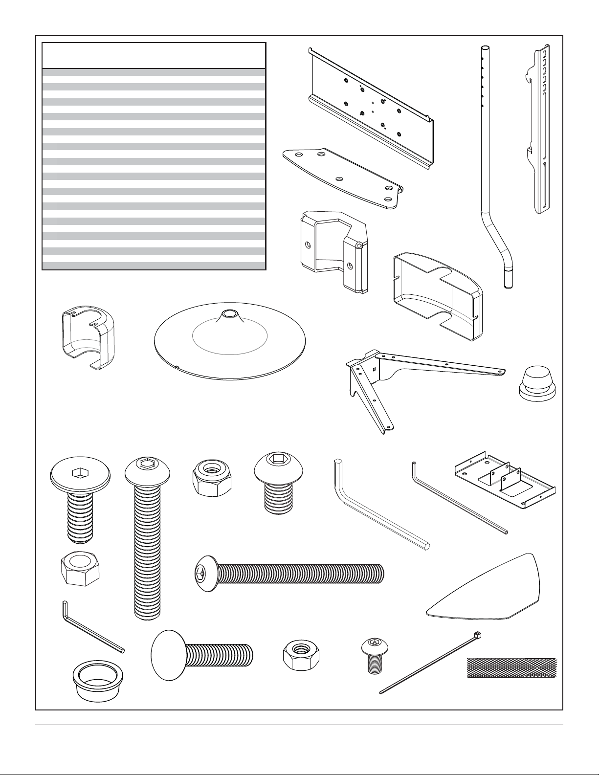
Security Adapter Bracket Fasteners
M5 x 12mm (4)
(520-1064)
M5 x 25mm (4)
(520-1122)
M6 x 12mm (4)
(520-1050)
M6 x 25mm (4)
(520-1211)
M8 x 12mm (4)
(520-1724)
M8 x 25mm (4)
(520-1101)
.75" spacer (4)
(540-1059)
Multi-washer (4)
(580-1398)
4 of 33
ISSUED: 1-25-11 SHEET #: 125-9150-7 09-28-12
Page 5
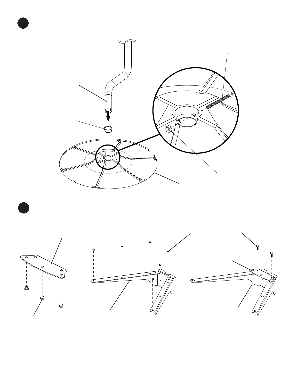
Attach vertical tube (B) to support base (H) using one plastic bushing (AA), one M5 x 55 mm socket screw (R), and
1
M5 nut (S) as shown in detail 1. Tighten M5 x 55 mm socket pin screw (R) using 4 mm allen wrench (X).
R
DETAIL 1
B
AA
H
Press three button bumpers (J) into shelf clamp bracket (C) as shown in fi gure 2.1
2
Press six button bumpers (J) into shelf support (I) as shown in fi gure 2.2.
Loosely fasten two 1/4-20 x 20 mm decorative screws (K) as shown in fi gure 2.3.
C
I
J
S
J
K
C
I
Figure 2.1 Figure 2.2
5 of 33
Figure 2.3
ISSUED: 1-25-11 SHEET #: 125-9150-7 09-28-12
Page 6
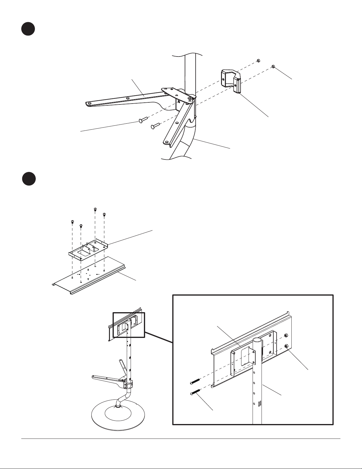
Attach shelf support (I) to vertical tube (B) with clamp bracket (D) using two 1/4-20 x 1.25" carriage bolts (T), and
3
1/4-20 nuts (U).
I
U
D
T
B
Attach adapter support plate (Q) to adapter plate (A) with four M10 x 15 mm socket screws (N)
4
using allen wrench (O) as shown in fi gure 4.1.
Attach adapter support plate (Q) to vertical tube (B) using two 5/16-18 x 2" socket screws (L), and 5/16 nuts (M)
as shown in detail 2.
N
A
Q
DETAIL 2
Q
M
6 of 33
B
L
ISSUED: 1-25-11 SHEET #: 125-9150-7 09-28-12
Page 7
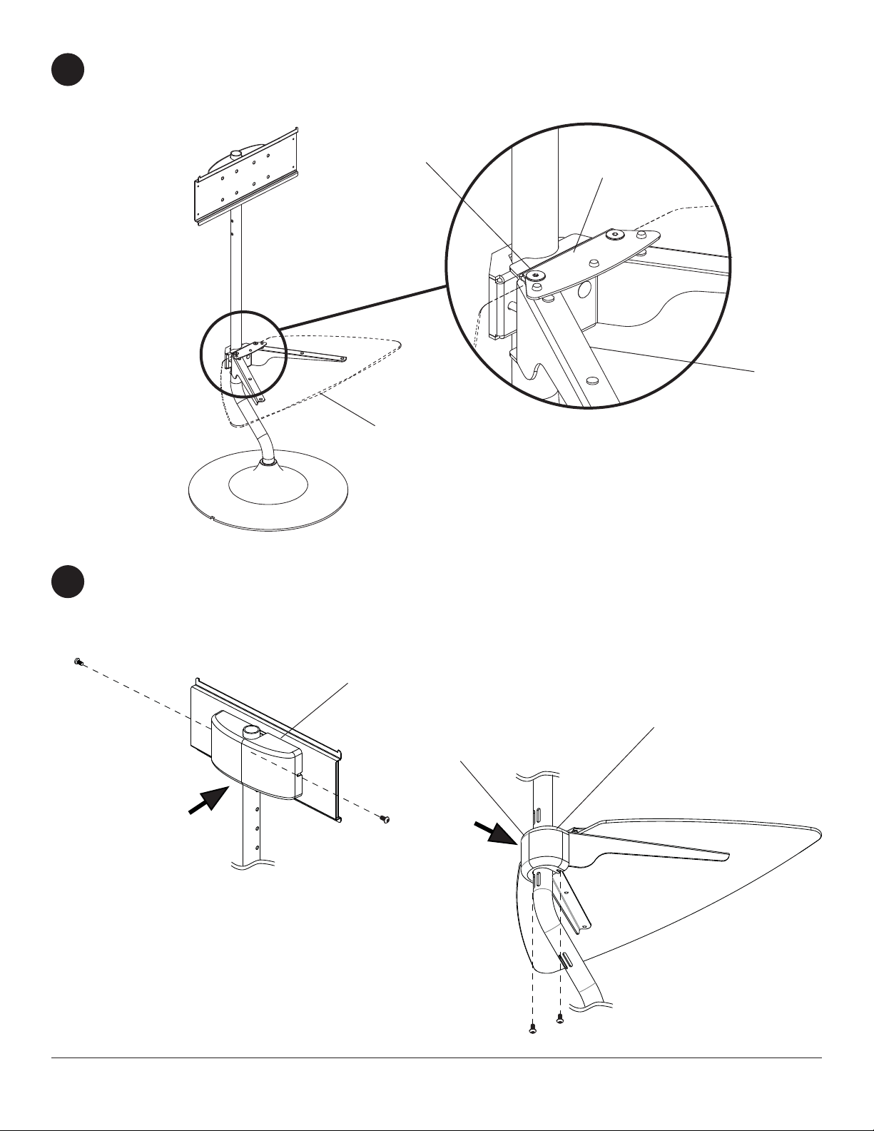
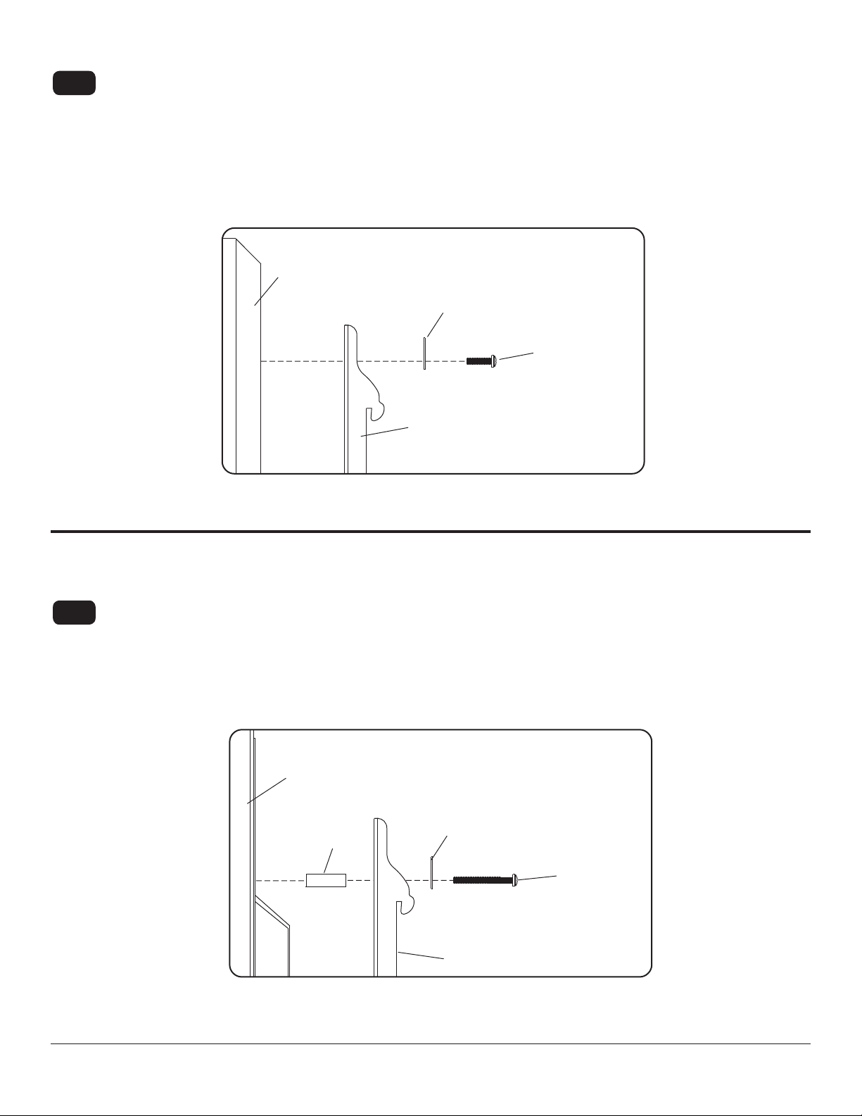
Position glass shelf (W) on top of shelf support (I) and under shelf clamp bracket (C) as shown below.
5
Secure glass shelf (W) in place by tightening two pre-installed 1/4-20 x 20 mm decorative screws (K)
as shown in detail 3.
K
C
I
W
Attach top cover (F) to adapter support plate (Q) with two M5 x 10 mm socket pin screws (V) as shown below.
6
Attach bottom cover (G) to clamp bracket (D) with two M5 x 10 mm socket pin screws (V) as shown below.
DETAIL 3
V
F
G
D
FIGURE 6.1
7 of 33
FIGURE 6.2
V
ISSUED: 1-25-11 SHEET #: 125-9150-7 09-28-12
Page 8
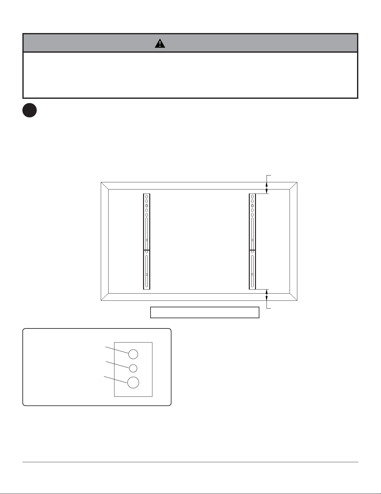
Installing Adapter Brackets
WARNING
• Tighten screws so adapter brackets are fi rmly attached. Do not tighten with excessive force. Overtightening can
cause stress damage to screws, greatly reducing their holding power and possibly causing screw heads to become
detached. Tighten to 40 in. • lb (4.5 N.M.) maximum torque.
• If screws don't get three complete turns in the screen inserts or if screws bottom out and bracket is still not tightly
secured, damage may occur to screen or product may fail.
To prevent scratching the screen, set a cloth on a fl at, level surface that will support the weight of the screen. Place
7
screen face side down. If screen has knobs on the back, remove them to allow the adapter brackets to be attached.
Place adapter brackets (E) on back of screen, align to holes, and center on back of screen as shown below. Attach
the adapter brackets to the back of the screen using the appropriate combination of screws, multi-washers, and
spacers as shown in fi gure 7.1 and 7.2.
NOTE: Top and bottom holes must always be used.
Verify that all holes are properly aligned, and then tighten screws using a phillips screwdriver.
X
MEDIUM HOLE FOR M5 SCREWS
SMALL HOLE FOR M4 SCREWS
LARGE HOLE FOR M6 SCREWS
E
MULTI-WASHER
CENTER BRACKETS
VERTICALLY ON BACK OF
SCREEN
Note: "X" dimensions should be equal.
Notes:
• The number of fasteners used will vary, depending
upon the type of screen.
• Multi-washers and spacers may not be used,
depending upon the type of screen.
• Use the corresponding hole in the multi-
washer that matches your screw size as shown.
X
NOTE: For fl at back screens proceed to step 7-1. For bump-out or recessed back screen skip to step 7-2.
8 of 33
ISSUED: 1-25-11 SHEET #: 125-9150-7 09-28-12
Page 9
For Flat Back Screen
Begin with the shortest length screw, hand thread through multi-washer and adapter bracket into screen as shown
7-1
below. Screw must make at least three full turns into the mounting hole and fi t snug into place. Do not over tighten.
If screw cannot make three full turns into the screen, select a longer length screw from the baffl ed fastener pack.
Repeat for remaining mounting holes, level brackets and tighten screws.
NOTE: Spacers may not be used, depending upon the type of screen.
fi g. 7.1
SCREEN
MULTI-WASHER
SCREW
ADAPTER
BRACKET (E)
If you have any questions, please call Peerless customer care at 1-800-865-2112.
For Bump-out or Recessed Back Screen
Begin with longer length screw, hand thread through multi-washer, adapter bracket and spacer in that order into
7-2
screen as shown below. Screw must make at least three full turns into the mounting hole and fi t snug into place.
Do not over tighten. If screw cannot make three full turns into the screen, select a longer length screw from the
baffl ed fastener pack. Repeat for remaining mounting holes, level brackets and tighten screws.
SCREEN
SPACER
fi g. 7.2
MULTI-WASHER
SCREW
ADAPTER BRACKET (E)
If you have any questions, please call Peerless customer care at 1-800-865-2112.
9 of 33
ISSUED: 1-25-11 SHEET #: 125-9150-7 09-28-12
Page 10

Mounting and Removing Flat Panel Screen
WARNING
• Always use an assistant or mechanical lifting equipment to safely lift and position the plasma television.
Hook adapter brackets (E) onto adapter plate (A), then slowly swing screen in as shown. Turn screws clockwise at
8
least six times to prevent screen from being removed as shown in detail 4.
NOTE: Tighten using 4 mm allen wrench (P).
Screen can be adjusted horizontally if desired.
NOTE: It is important to lock screen down! To lock the screen down, tighten screws to adapter bracket as shown
in detail 4.
To remove screen from mount, loosen screws, swing screen away from mount and lift screen off of mount.
SCREWS
A
A
E
E
DETAIL 4
10 of 33
ISSUED: 1-25-11 SHEET #: 125-9150-7 09-28-12
Page 11

Run screen cables through two 18" mesh sleeves (Y) as shown below.
9
Secure screen cables and two 18" mesh sleeves (Y) to vertical tube (B) with fi ve cable ties (X) into slots on back of
vertical tube (B).
SCREEN
B
Y
SLOTS
X
Y
11 of 33
ISSUED: 1-25-11 SHEET #: 125-9150-7 09-28-12
Page 12

Español
Instalación y ensamblaje: Estante para televisor de pantalla
plana de 32" - 46"
Modelos: FPZ-646
12 de 33
Máxima capacidad de carga:
100 lb (45 kg) screen
25 lb (11 kg) per shelf
PUBLICADO: 1-25-11 HOJA #: 125-9150-7 09-28-12
Page 13

Español
NOTE: Read entire instruction sheet before you start installation and assembly.
ADVERTENCIA
• No comience a instalar su producto de Peerless hasta haber leído y entendido las instrucciones y las advertencias
contenidas en la Hoja de Instalación. Si tiene alguna pregunta acerca de cualquiera de las instrucciones o las advertencias, por favor, llame a Servicio al Cliente de Peerless al 1-800-865-2112 si está en EE. UU. Si es un cliente
internacional, por favor, comuníquese con su distribuidor local.
• Este producto sólo debe ser instalado por una persona que tenga una buena aptitud mecánica, que tenga experiencia en construcción básica de edifi cios y que entienda estas instrucciones en su totalidad.
• Asegúrese de que la superfi cie de apoyo sostendrá, con seguridad, la carga combinada del equipo y todos los fi -
jadores y componentes.
• Nunca sobrepase la capacidad máxima de soportar carga.
• Siempre cuente con la ayuda de un asistente o utilice un equipo mecánico de izar para levantar y colocar el equipo
con más seguridad.
• Apriete los tornillos con fi rmeza, pero no en exceso. Apretarlos en exceso puede dañar los artículos y puede disminu-
ir signifi cativamente su fuerza de fi jación.
Herramientas necesarias para el ensamblaje
• destornillador phillips
• nivel
Vea la página 12.
Contenido
Lista de piezas..................................................................................................................................................................... 14
poner el apoyo juntos ..........................................................................................................................................................16
Fijar la placa de adaptador universal o placa adaptadora Dedicado .................................................................................. 17
Instalación de los soportes adaptadores ............................................................................................................................. 19
Llevar los cables de la pantalla ........................................................................................................................................... 22
13 de 33
PUBLICADO: 1-25-11 HOJA #: 125-9150-7 09-28-12
Page 14

Español
C
d
N.od
A
V
Y
A
Lista de piezas
Descripción
placa adaptadora
B 1 104-P1075
tubo vertical
C 1 201-P1159
soporte de abrazadera para repisas
D 1 104-P1072
soporte sostenedor para repisas
E 2 201-P1512
soporte adaptador
F cubierta superior 1 590-P1340
G cubierta inferior 1 590-P1341
H base sostenedora 1 590-1039
I soporte de apoyo para repisas 1 104-P1073
J 9 590-1209
paragolpe de botón
K 2 520-2326
tornillo decorativo de 1/4-20 x 20
L 2 520-1116
tornillo de cabeza hueca de 5/16-18 x 2/1.75”
M tuerca de 5/16 2 530-9306
N 4 520-9262
tornillo de cabeza hueca M10 x 15 mm
O 1 560-9716
llave allen de 6 mm
P 1 560-9646
llave allen de 4 mm
Q 1 104-P1074
placa adaptadora sostenedora
R 1 520-1302
tornillo pasador de cabeza hueca de M5 x 55 mm
S tuerca de M5 1 530-9409
T 2 560-1764
perno de cabeza redonda de 1/4-20 x 1.75"
U tuerca de 1/4-20 2 530-9302
tornillo pasador de cabeza hueca de M5 x 10 mm
W 1 590-0208
repisa de cristal
X sujetacables 5 560-9711
funda de malla de 18”
llave allen de 3/16”
Z 1 560-0071
casquillo de plástico
A
G
H
antida
1 201-P1016
4 520-1063
2 600-1014
1 590-1378
e pieza
C
D
A
B
E
F
I
J
S
Z
AA
K
L
MN
R
T
UV
O
P
Q
W
Y
X
14 de 33
PUBLICADO: 1-25-11 HOJA #: 125-9150-7 09-28-12
Page 15

Español
Fijaciones de seguridad para los soportes adaptadores
M5 x 12mm (4)
(520-1064)
M5 x 25mm (4)
(520-1122)
M6 x 12mm (4)
(520-1050)
M6 x 25mm (4)
(520-1211)
M8 x 12mm (4)
(520-1724)
M8 x 25mm (4)
(520-1101)
.75" espaciador (4)
(540-1059)
arandela múltiple (4)
(580-1398)
15 de 33
PUBLICADO: 1-25-11 HOJA #: 125-9150-7 09-28-12
Page 16

Fije el tubo vertical (B) en la base sostenedora (H) utilizando un casquillo de plástico (AA), un tornillo pasador de
1
cabeza hueca de M5 x 55 mm (R) y una tuerca de M5 (S), como se muestra en el detalle 1.
R
DETALLE 1
B
AA
Español
S
H
Inserte tres paragolpes de botón (J) en el soporte de abrazadera para repisas (C), como se muestra
2
en la fi gura 2.1.
Inserte seis paragolpes de botón (J) en el soporte de apoyo para repisas (I), como se muestra en la fi gura 2.2.
Ajuste los dos tornillos decorativos de 1/4-20 x 20 mm (K) sin apretarlos, como se muestra en la fi gura 2.3.
C
J
K
C
I
I
J
FIGURA 2.1
FIGURA 2.2
16 de 33
FIGURA 2.3
PUBLICADO: 1-25-11 HOJA #: 125-9150-7 09-28-12
Page 17

Fije el soporte de apoyo para repisas (I) en el tubo vertical (B) con el soporte sostenedor (D) utilizando dos pernos
3
de cabeza redonda (T) y dos tuercas de 1/4-20 (U).
I
U
D
T
B
Fije la placa adaptadora sostenedora (Q) a la placa adaptadora (A) con cuatro tornillos de cabeza hueca (N)
4
utilizando una llave allen (O).
Fije la placa adaptadora sostenedora (Q) en el tubo vertical (B) utilizando dos tornillos de cabeza hueca de 5/16-18
x 2” (L) y dos tuercas de 5/16 (M), como se muestra en el detalle 2.
Español
N
A
Q
DETALLE 2
Q
M
17 de 33
B
L
PUBLICADO: 1-25-11 HOJA #: 125-9150-7 09-28-12
Page 18

Coloque la repisa de cristal (W) encima del soporte de apoyo para repisas (I) y debajo del soporte de abrazadera
5
para repisas (C), como se muestra abajo. Fije la repisa de cristal (W) en su lugar apretando los dos tornillos
decorativos de 1/4-20 x 20 mm (K) preinstalados, como se muestra en el detalle 3.
K
C
Español
I
W
Coloque la cubierta superior (F) a la placa adaptadora de apoyo (Q) con dos M5 x 10 mm tornillos de cabeza
6
hueca pasador (V) como se muestra en la fi gura 6.1.
Fije la cubierta inferior (G) para fi jar el soporte (D) con dos M5 x 10 mm tornillos de cabeza hueca pasador (V)
como se muestra en la fi gura 6.2.
V
DETALLE 3
F
G
D
FIGURA 6.1
18 de 33
FIGURA 6.2
V
PUBLICADO: 1-25-11 HOJA #: 125-9150-7 09-28-12
Page 19

Instalación de los soportes adaptadores
ADVERTENCIA
• Apriete los tornillos de tal modo que los soportes adaptadores queden fi rmemente sujetos. No apriete aplicando
demasiada fuerza. El apriete excesivo puede causar daño por esfuerzo a los tornillos, reduciendo enormemente su
fuerza de fi jación y causando el posible desprendimiento de sus cabezas. Apriete los tornillos a 40 pulg-lb (4.5 N•m)
de par torsor máximo.
• Si los tornillos no pueden atornillarse con tres vueltas completas en los insertos de la pantalla, o si los tornillos topan
fondo y la placa todavía no está fi rmemente sujeta, se podría dañar la pantalla o causar la falla del producto.
Para no rayar la pantalla, coloque un trapo sobre una superfi cie plana y nivelada que sostenga el peso de la pan-
2
talla. Coloque la pantalla boca abajo. Si la pantalla tiene perillas en la parte trasera, quíteselas para poder fi jar los
soportes adaptadores. Coloque los soportes adaptadores (E) en la parte trasera de la pantalla, alinéelos con los
agujeros y centralícelos en la parte trasera de la pantalla, como se muestra abajo. Fije los soportes adaptadores
en la parte trasera de la pantalla utilizando la combinación adecuada de tornillos, arandelas y espaciadores, como
se muestra en la fi gura 7.1 o en la fi gura 7.2.
NOTA: Siempre se tienen que usar los agujeros superiores y los inferiores.
Verifi que que todos los agujeros estén debidamente alineados y luego apriete los tornillos usando un destornillador
phillips.
X
ARANDELA MÚLTIPLE
CENTRE LOS SOPORTES
VERTICALMENTE EN LA
E
NOTA: Las dimensiones “X” deben ser iguales.
AGUJERO MEDIANO PARA
AGUJERO PEQUEÑO PARA
AGUJERO GRANDE PARA
PARTE TRASERA DE LA
PANTALLA
TORNILLOS M5
TORNILLOS M4
TORNILLOS M6
Notas:
• La cantidad de fi jaciones utilizada variará según el tipo
de pantalla.
• Es posible que no tenga que usar las arandelas
múltiples y los espaciadores, dependiendo del tipo de
pantalla.
• Use el agujero correspondiente en la arandela múltiple
que coincida con el tamaño de su tornillo, como se
muestra en la fi gura 7.2.
X
NOTA: En el caso de los televisores que tienen la parte posterior plana, pase al paso 7-1. En el caso de los televisores
que tienen la parte posterior abultada o empotrada, pase al paso 7-2.
19 of 33
ISSUED: 1-25-11 SHEET #: 125-9150-7 09-28-12
Page 20

Instalación de un televisor que tiene la parte posterior plana
Comience con uno de los tornillos más cortos, enrósquelo, con la mano, a través de la arandela y el soporte
7-1
adaptador a la parte posterior de la pantalla, como se muestra abajo. El tornillo debe dar, por lo menos, tres
vueltas completas dentro del agujero de instalación y debe quedar ajustado en su lugar. No apriete los tornillos en
exceso. Si el tornillo no puede dar tres vueltas completas al entrar en la parte posterior de la pantalla, seleccione
un tornillo más largo de los sujetadores identifi cados y clasifi cados en las divisiones del empaque plástico. Siga el
mismo procedimiento con los agujeros de instalación restantes, nivele los soportes y apriete los tornillos.
NOTA: Es posible que no necesite usar los espaciadores, dependiendo del tipo de pantalla.
Español
PANTALLA
ARANDELA MÚLTIPLE
SOPORTE ADAPT ADOR (E)
Si tiene alguna pregunta, por favor, llame a servicio al cliente de Peerless al 1-800-865-2112.
FIGURA 7.1
TORNILLO
Instalación de un televisor que tiene la parte posterior abultada o empotrada
Comience con uno de los tornillos más largos, enrósquelo, con la mano, a través de la arandela, el soporte
7-2
adaptador y el espaciador, en ese orden, a la parte posterior de la pantalla, como se muestra abajo. El tornillo
debe dar, por lo menos, tres vueltas completas dentro del agujero de instalación y debe quedar ajustado en su
lugar. No apriete los tornillos en exceso. Si el tornillo no puede dar tres vueltas completas al entrar en la parte
posterior de la pantalla, seleccione un tornillo más largo de los sujetadores identifi cados y clasifi cados en las
divisiones del empaque plástico. Siga el mismo procedimiento con los agujeros de instalación restantes, nivele los
soportes y apriete los tornillos.
FIGURA 7.2
PANTALLA
SPACER
Si tiene alguna pregunta, por favor, llame a servicio al cliente de Peerless al 1-800-865-2112.
20 de 33
ARANDELA MÚLTIPLE
TORNILLO
SOPORTE ADAPT ADOR (E)
PUBLICADO: 1-25-11 HOJA #: 125-9150-7 09-28-12
Page 21

Español
Montaje y desmontaje de la pantalla plana
ADVERTENCIA
• Siempre cuente con un asistente o con un equipo mecánico de izar para levantar y colocar los televisores de pantalla
plana con más seguridad.
Enganche los soportes adaptadores (E) en la placa de pared (A). Entonces gire la pantalla lentamente, como
8
se muestra. Déles, por lo menos, seis vueltas a los tornillos de seguridad en el sentido del movimiento de las
manecillas del reloj con una llave allen de seguridad (FF).
La pantalla se puede ajustar horizontalmente si lo desea.
NOTA: Para trabar la pantalla, apriete los tornillos de seguridad a la placa de pared, como se muestra en la
sección transversal.
Para quitar la pantalla del soporte, afl oje los tornillos de seguridad, gire la pantalla retirándola del soporte y
levántela para sacarla del soporte.
ATENCIÓN
• No apriete los tornillos aplicando demasiada fuerza. El
apriete excesivo podría dañar el soporte. Apriete los
tornillos a 40 pulg-lb (4.5 N•m) de par torsor máximo.
TORNILLOS
DE SEGURIDAD
A
E
SECCIÓN
TRANSVERSAL
A
E
21 de 33
PUBLICADO: 1-25-11 HOJA #: 125-9150-7 09-28-12
Page 22

Llevar los cables de la pantalla a través de dos mangas de malla de 18” (Y) como se muestra en la fi gura.
9
Asegure los cables de la pantalla y dos de 18” mangas de malla (Y) en el tubo vertical (B) con cinco ataduras de
cables (X) en las ranuras en la parte posterior del tubo vertical (B).
PANTALLA
B
Y
Español
LAS RANURAS
X
Y
22 de 33
PUBLICADO: 1-25-11 HOJA #: 125-9150-7 09-28-12
Page 23

Installation et montage: 32"- 46" télé à écran plat
Modèles: FPZ-646
Français
23 sur 33
Capacité de charge
maximale préconisée:
100lb (45 kg) écran
25 lb (11 kg) étagère en verre
PUBLIÉ LE : 1-25-11 FEUILLE no : 125-9150-7 09-28-12
Page 24

Français
REMARQUE: lisez entièrement la fi che d’instructions avant de commencer l’installation et l’assemblage.
AVERTISSEMENT
• Ne commencez pas à installer votre produit Peerless avant d’avoir lu et assimilé les instructions et les avertissements contenus dans cette fi che d’installation. Pour toute question concernant les instructions ou les avertissements,
veuillez appeler le service à la clientèle de Peerless au 1-800-865-2112; tous les clients internationaux sont priés de
contacter leur distributeur local.
• Ce produit doit être installé uniquement par quelqu’un possédant une bonne aptitude à la mécanique, une expérience
de la construction immobilière et ayant bien compris ces instructions.
• Assurez-vous que la surface de support puisse soutenir sans danger la charge totale de l’équipement ainsi que des
pièces et composants qui y sont attachés.
• Ne dépassez jamais la capacité de charge maximum. Reportez-vous à la page 23.
• Pour lever et positionner l’équipement en toute sécurité, faites-vous toujours aider par une autre personne ou utilisez
un dispositif de levage mécanique.
• Serrez fermement les vis, mais sans excès. Un serrage excessif peut endommager les composants et en réduire
considérablement la capacité de support.
Outils nécessaires au montage
• tournevis phillips
• niveau
Table des matières
Liste des pièces ....................................................................................................................................................................25
Installation sur un mur à doubles montants en bois .............................................................................................................27
Installation sur du béton plein ou un bloc de béton de mâchefer .........................................................................................28
Installation de support inclinables.........................................................................................................................................30
d’écran les câbles ................................................................................................................................................................33
24 sur 33
PUBLIÉ LE : 1-25-11 FEUILLE no : 125-9150-7 09-28-12
Page 25

Français
A
V
Y
A
Liste des pièces
Description
plaque d’adaptation
B 1 104-P1075
tube vertical
C 1 201-P1159
pince de fixation pour étagère
D 1 104-P1072
patte de support pour étagère
E 2 201-P1512
support adaptateur
F couvercle supérieur 1 590-P1340
G couvercle inférieur 1 590-P1341
H base de support 1 590-1039
I support pour étagère 1 104-P1073
embout de protection
J 9 590-1209
vis décorative 1/4-20 x 20 mm
K 2 520-2326
vis à tête creuse 1/4-20 x 2 po
L 2 520-1116
M écrou 5/16 2 530-9306
vis à tête creuse M10 x 15 mm
N 4 520-9262
clé hexagonale de 6 mm
O 1 560-9716
clé hexagonale de 4 mm
P 1 560-9646
plaque du support d’adaptation
Q 1 104-P1074
vis à tête creuse M5 x 55 mm
R 1 520-1302
S Écrou M5 1 530-9409
T 2 560-1764
boulon de carrosserie de 1/4-20 x 1,75 po
U écrou 1/4-20 2 530-9302
vis à tête creuse M5 x 10 mm
W 1 590-0208
étagère en verre
X attache de câble 5 560-9711
enveloppe en maille de 18 po
Z 1 560-0071
clé hexagonale de 3/16 po
bague en plastique
A
G
H
Qté Pièce no
1 201-P1016
4 520-1063
2 600-1014
1 590-1378
C
D
A
B
E
F
I
S
Z
K
L
MN
R
T
UV
O
P
J
Q
W
Y
X
AA
25 sur 33
PUBLIÉ LE : 1-25-11 FEUILLE no : 125-9150-7 09-28-12
Page 26

Fixations de sécurité du support adaptateur
Français
M5 x 12mm (4)
(520-1064)
M5 x 25mm (4)
(520-1122)
M6 x 12mm (4)
(520-1050)
M6 x 25mm (4)
(520-1211)
M8 x 12mm (4)
(520-1724)
M8 x 25mm (4)
(520-1101)
.75" entretoise (4)
(540-1059)
rondelle tout usage (4)
(580-1398)
26 sur 33
PUBLIÉ LE : 1-25-11 FEUILLE no : 125-9150-7 09-28-12
Page 27

Fixez le tube vertical (B) à la base de support (H) à l’aide d’une bague en plastique (AA), d’une vis à tête creuse
1
M5 x 55 mm (R) et d’un écrou M5 (S) comme illustré dans le dessin de détail 1.
R
DÉTAIL 1
B
AA
Français
S
H
Enfoncez trois embouts de protection (J) dans la pince de fi xation pour étagère (C) comme illustré à la fi gure 2.1
2
Enfoncez six embouts de protection (J) dans le support pour étagère (I) comme illustré à la fi gure 2.2.
Serrez légèrement deux vis décoratives (K) de 1/4-20 x 20 mm (K) comme illustré à la fi gure 2.3.
C
J
K
C
I
I
J
Figure 2.1 Figure 2.2
27 sur 33
Figure 2.3
PUBLIÉ LE : 1-25-11 FEUILLE no : 125-9150-7 09-28-12
Page 28

Fixez le support pour étagère (I) au tube vertical (B) avec la pince de fi xation pour étagère (D) à l’aide de deux
3
boulons de carrosserie 1/4-20 x 1,25 po (T) et d’écrous 1/4-20 (U).
I
U
D
T
B
Fixez la plaque du support d’adaptation (Q) à la plaque d’adaptation (A) avec quatre vis à tête creuse M10 x 15
4
mm (N) à l’aide d’une clé hexagonale (O).
Fixez la plaque du support d’adaptation (Q) au tube vertical (B) à l’aide de deux vis à tête creuse 5/16-18 x 2 po (L)
et d’écrous 5/16 (M) comme illustré dans le dessin de détail 2.
Français
N
A
Q
DÉTAIL 2
Q
M
28 sur 33
B
L
PUBLIÉ LE : 1-25-11 FEUILLE no : 125-9150-7 09-28-12
Page 29

Placez l’étagère en verre (W) sur le support pour étagère (I) et sous la pince de fi xation pour étagère (C) comme
5
illustré ci-dessous. Fixez l’étagère en verre (W) en place en serrant les deux vis décoratives 1/4-20 x 20 mm
préinstallées (K) comme illustré dans le dessin de détail 3.
K
C
Français
I
W
Fixez le couvercle supérieur (F) à la plaque de support adaptateur (Q) avec deux M5 x 10 mm vis à tête creuse (V)
6
comme le montre la fi gure 6.1.
Fixez le couvercle inférieur (G) pour le support de serrage (D) avec deux M5 x 10 mm vis à tête creuse (V) comme
le montre la fi gure 6.2.
DÉTAIL 3
V
F
G
D
FIGURE 6.1
29 sur 33
FIGURE 6.2
V
PUBLIÉ LE : 1-25-11 FEUILLE no : 125-9150-7 09-28-12
Page 30

Français
Installation des supports adaptateurs
AVERTISSEMENT
• Serrez les vis de manière que les supports adaptateurs soient solidement fi xés. N’employez pas une force excessive
pour serrer. Un serrage excessif peut causer des contraintes risquant d’endommager les vis, de réduire considérablement leur pouvoir de maintien et de décoller les têtes des vis. Serrez les vis à un couple maximum de 4,5 Nm (40
po-lb).
• Si les vis ne sont pas enfoncées de trois tours complets dans les inserts ou si elles sont serrées au maximum sans
parvenir à maintenir solidement le support, l’écran peut être abîmé ou le produit détérioré.
Pour éviter de rayer l’écran, placez un chiffon sur une surface plate et horizontale capable de soutenir le poids de
7
l’écran. Placez l’écran sens dessus dessous. Si l’écran est muni de boutons à l’arrière, enlevez-les pour pouvoir
fi xer les supports adaptateurs. Placez les supports adaptateurs (E) à l’arrière de l’écran, alignez-les sur les trous
et centrez-les sur l’arrière de l’écran, comme illustré ci-dessous. Fixez les supports adaptateurs à l’arrière de
l’écran à l’aide des vis, rondelles et entretoises appropriées, comme illustré à la fi gure 7.1 ou 7.2.
REMARQUE : Les trous supérieurs et inférieurs doivent toujours être utilisés.
Vérifi ez que tous les trous sont correctement alignés, puis serrez les vis à l’aide d’un tournevis cruciforme.
X
RONDELLE UNIVERSELLE
E
CENTREZ LES SUPPORTS
VERTICALEMENT À L’ARRIÈRE
DE L’ÉCRAN
X
REMARQUE : LES DIMENSIONS « X » DOIVENT ÊTRE ÉGALES.
TROU MOYEN POUR VIS M5
PETIT TROU POUR VIS M4
GROS TROU POUR VIS M6
Remarques :
• Le nombre de fi xations utilisées varie suivant
le type d’écran.
• Il est possible que les rondelles universelles
et les entretoises ne soient pas utilisées,
suivant le type d’écran.
• Utilisez le trou correspondant dans la
rondelle universelle adaptée à la taille de vis.
REMARQUE : Pour les écrans à dos plat, exécutez l’étape 7-1. Pour les écrans à dos convexes ou concaves passez
à l’étape 7-2.
30 sur 33
PUBLIÉ LE : 1-25-11 FEUILLE no : 125-9150-7 09-28-12
Page 31

Pour les écrans à dos plat
Commencez par la vis la plus courte et vissez-la manuellement à l’écran en la faisant passer à travers la rondelle
7-1
tout usage et le support adaptateur, comme indiqué ci-dessous. La vis doit effectuer au moins trois tours complets
dans le trou de fi xation et tenir solidement en place. Ne pas trop serrer. S’il est impossible d’effectuer trois tours
de vis complets, choisissez une vis plus longue dans le jeu de fi xations à compartiments. Répétez pour le reste
des trous de fi xations, mettez les supports à niveau et resserrez les vis.
REMARQUE : Il n’est pas toujours nécessaire d’utiliser des entretoises, selon le type d’écran.
Français
ÉCRAN
Pour toute question, veuillez appeler le service à la clientèle de Peerless au 1-800-865-2112.
Pour un écran à dos convexe ou concave
Commencez par la vis la plus longue et vissez-la manuellement à l’écran en la faisant passer à travers la rondelle
7-2
tout usage, le support adaptateur et l’entretoise comme indiqué ci-dessous. La vis doit effectuer au moins
trois tours complets dans le trou de fi xation et tenir solidement en place. Ne pas trop serrer. S’il est impossible
d’effectuer trois tours de vis complets, choisissez une vis plus longue dans le jeu de fi xations à compartiments.
Répétez pour le reste des trous de fi xations, mettez les supports à niveau et resserrez les vis.
fi g 7.1
RONDELLE TOUT
USAGE
VIS
SUPPORT ADAPT ATEUR (E)
ÉCRAN
fi g 7.2
ENTRETOISE
Pour toute question, veuillez appeler le service à la clientèle de Peerless au 1-800-865-2112.
31 sur 33
RONDELLE TOUT
USAGE
VIS
SUPPORT ADAPT ATEUR (E)
PUBLIÉ LE : 1-25-11 FEUILLE no : 125-9150-7 09-28-12
Page 32

Français
Montage et démontage de l’écran plat
AVERTISSEMENT
• Pour lever et positionner l’écran plat en toute sécurité, faites-vous toujours aider par une autre personne ou utilisez un
dispositif de levage mécanique.
Accrochez les supports adaptateurs (E) à la plaque murale (A). Puis, faites pivoter lentement l’écran vers l’intérieur,
8
comme illustré. Tournez les vis de sûreté/sécurité à l’aide d’une clé hexagonale (P) au moins six fois dans le sens
horaire pour éviter le retrait de l’écran comme illustré dans la coupe transversale de la fi g. 8.1. L’écran peut être
réglé horizontalement selon le besoin comme illustré à la fi g. 8.2.
REMARQUE : Pour verrouiller l’écran, serrez les vis se sûreté/sécurité à la plaque murale comme illustré dans la
coupe transversale.
Pour retirer l’écran du support, desserrez les vis de sûreté/sécurité, faites pivoter l’écran hors du support et
soulevez-le.
ATTENTION
• N’employez pas une force excessive pour serrer
les vis. Un serrage excessif peut endommager la
monture. Serrez les vis à un couple maximum de
4,5 Nm (40 po-lb).
VIS DE
SÛRETÉ/
SÉCURITÉ
A
E
COUPE
TRANSVERSALE
A
E
FIGURE 8.1
32 sur 33
PUBLIÉ LE : 1-25-11 FEUILLE no : 125-9150-7 09-28-12
Page 33

Passer les câbles d’écran par deux manchons 18 po mesh (Y), comme illustré dans la fi gure.
9
Câbles écran sécurisé et deux manchons 18 po mesh (Y) dans le tube vertical (B) avec cinq attaches de câble (X)
dans les fentes à l’arrière du tube vertical (B).
ÉCRAN
B
Y
Français
LES FENTES
X
Y
33 sur 33
All other brand and product names are trademarks or registered trademarks of their respective owners.
PUBLIÉ LE : 1-25-11 FEUILLE no : 125-9150-7 09-28-12
© 2012 Peerless Industries, Inc. All rights reserved.
Peerless is a registered trademark of Peerless Industries, Inc.
 Loading...