

peerless-AV FPE47FH-UK-S, FPE55F-S, FPE55F-UK-S, FPE47F-S, FPE55FH-UK-S Installation And Assembly Manual
...Page 1
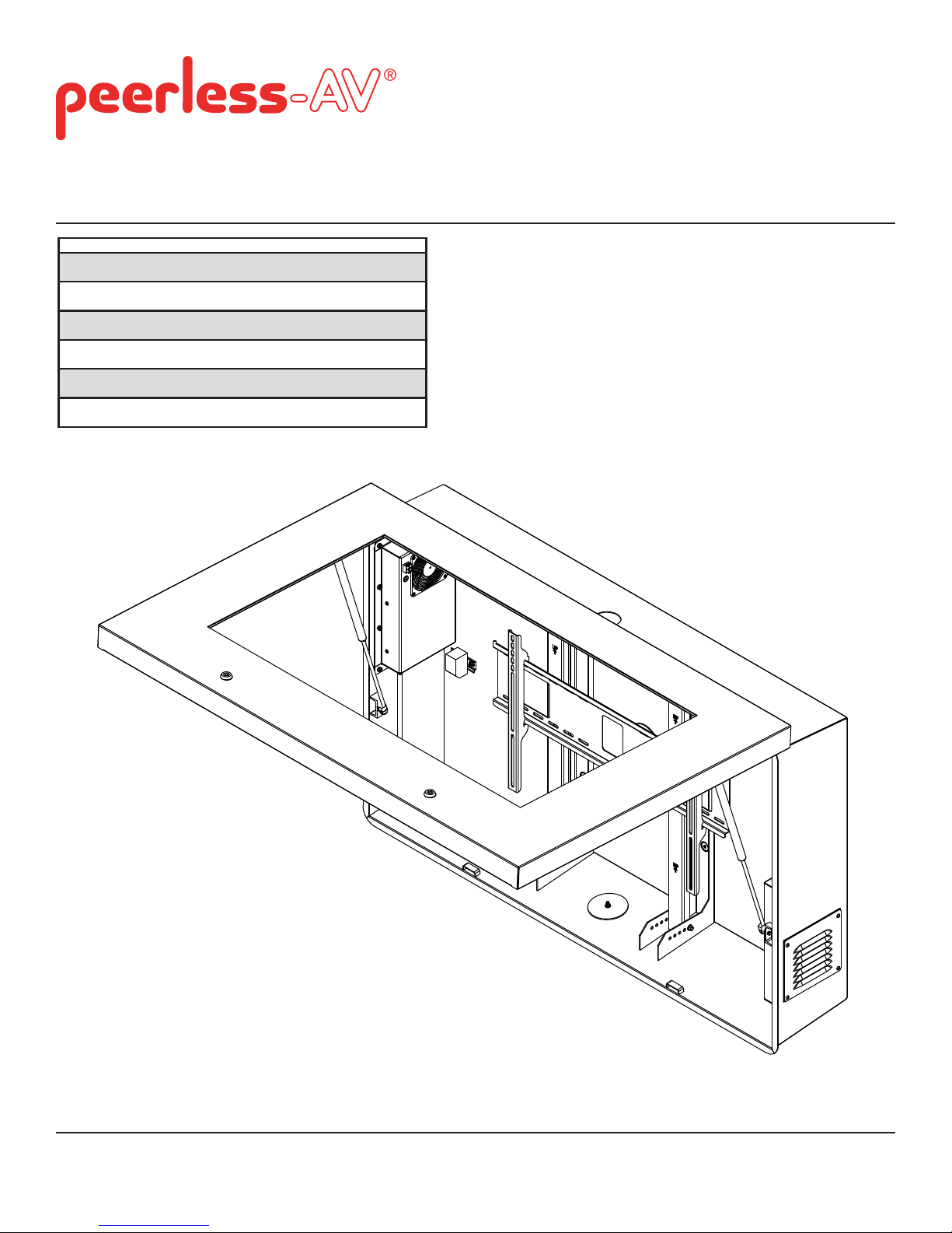
Installation and Assembly:
S
S
Peerless Environmental Enclosure for Flat Panel Displays
Model # Max Load Capacity Screen Size
FPE47F-S 250 lbs (113 kg) 46"-47"
FPE47FH-S 250 lbs (113 kg) 46"-47"
FPE55F-S 250 lbs (113 kg) 55"
FPE55FH-S 250 lbs (113 kg) 55"
FPE47F-UK-S 250 lbs (113 kg) 46"-47"
FPE47FH-UKFPE55F-UK-S 250 lbs (113 kg) 55"
FPE55FH-UKFPE47F-EU-S 250 lbs (113 kg) 46"-47"
FPE47FH-EU-S 250 lbs (113 kg) 46"-47"
FPE55F-EU-S 250 lbs (113 kg) 55"
FPE55FH-EU-S 250 lbs (113 kg) 55"
250 lbs (113 kg) 46"-47"
250 lbs (113 kg) 55"
2300 White Oak Circle • Aurora, Il 60502 • (800) 865-2112 • Fax: (800) 359-6500 • www.peerless-av.com
ISSUED: 07-12-10 SHEET #: 061-9056-8 03-05-13
Page 2
NOTE: Read entire instruction sheet before you start installation and assembly.
WARNING
• Do not begin to install your Peerless product until you have read and understood the instructions and warnings
contained in this Installation Sheet. If you have any questions regarding any of the instructions or warnings, for US
customers please call Peerless customer care at 1-800-865-2112, for all international customers, please contact
your local distributor.
• Due to outdoor environmental conditions such as strong wind gusts, heavy snow, hail, rain, etc. The environmental
enclosure and hardware, must be inspected at least once a year, and immediately following any time winds exceed
90 mph. A qualifi ed installer or inspector must check for signs of rust, loose fasteners, bent metal, etc. If evidence
of excessive wear, deterioration or any unsafe condition is observed, this product must be taken out of service
immediately. Direct all inquiries to customer care if you have any questions.
• Glass face of enclosure must avoid direct sunlight or damage to display may occur.
• This product should only be installed by someone of good mechanical aptitude, has experience with basic building
construction, and fully understands these instructions.
• Make sure that the supporting surface will safely support the combined load of the equipment and all attached
hardware and components.
• Never exceed the Maximum Load Capacity. See page one.
• If mounting to wood wall studs, make sure that mounting screws are anchored into the center of the studs. Use of
an "edge to edge" stud fi nder is highly recommended.
• Always use an assistant or mechanical lifting equipment to safely lift and position equipment.
• Tighten screws fi rmly, but do not overtighten. Overtightening can damage the items, greatly reducing their holding
power.
• This product was designed for use with other outdoor products only.
• This product was designed to be installed on the following wall construction only;
WALL CONSTRUCTION HARDWARE REQUIRED
• Wood Stud Included
• Wood Beam Included
• Solid Concrete Contact Qualifi ed Professional
• Cinder Block Contact Qualifi ed Professional
• Brick Contact Qualifi ed Professional
• Other or unsure? Contact Qualifi ed Professional
Tools Needed for Assembly
• stud fi nder ("edge to edge" stud fi nder is
recommended)
• drill
Table of Contents
Parts List ............................................................................................................................................................................... 3
Removing bay door ............................................................................................................................................................ 5-6
Wall installation .......................................................................................................................................................................7
Depth Adjustment .............................................................................................................. .....................................................8
Wall plate installation ..............................................................................................................................................................9
Reinstalling door ................................................................................................................................................................. 10
Attaching vertical brackets to display ............................................................................................................................ 11-12
Mounting display.................................................................................................................................................................. 13
Setting Thermostat ............................................................................................................ ..................................................14
Filter Replacement .............................................................................................................................................................. 16
• phillips screwdriver, 5 mm allen wrench,
fl athead screwdriver
• 5/32" (4 mm) bit for wood stud wall
• level
• hammer
2 of 50
ISSUED: 07-12-10 SHEET #: 061-9056-8 03-05-13
Page 3
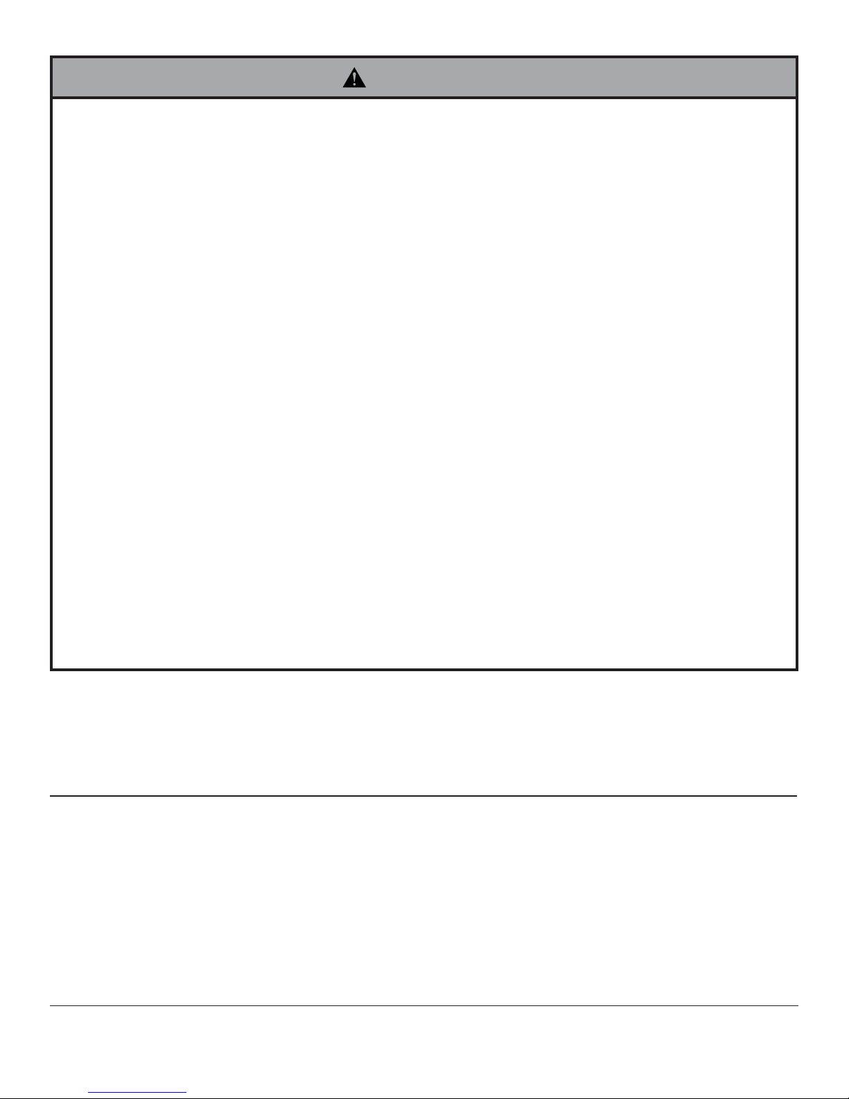
Before you begin, make sure all parts shown are included with your product.
r
y
t
Parts may appear slightly different than illustrated.
Parts List
Description Qty. Part #
A enclosure assembly 1 see chart
B adapter brackets 2 201-P1513
C wood screws 6 5S1-015-C03
sealed washe
E
F ROXTEC cable seal 1 600-0107
ke
G
H 12 mm flat head screw 4 520-2325
serrated locknu
I
J wall plate 1 201-P1018
K cord cover plate assembly (not shown) 2 061-7285
L 4 mm allen wrench 1 560-1727
1/2" spacer
M
6 540-4067
1 600-0116
4 530-2021
6 540-1059
Enclosure Assembly (A)
Model # Part #
FPE47F-S 061-7327
FPE47FH-S
FPE55F-S 061-7328
FPE55FH-S
FPE47F-UK-S 061-7585
FPE47FH-UK-S
FPE55F-UK-S 061-7586
FPE55FH-UK-S
FPE47F-EU-S 061-7590
FPE47FH-EU-S
FPE55F-EU-S 061-7592
FPE55FH-EU-S
B
A
061-7564
061-7565
061-7579
061-7583
061-7589
061-7591
C
J
F
E
L
H
G
I
M
3 of 50
ISSUED: 07-12-10 SHEET #: 061-9056-8 03-05-13
Page 4
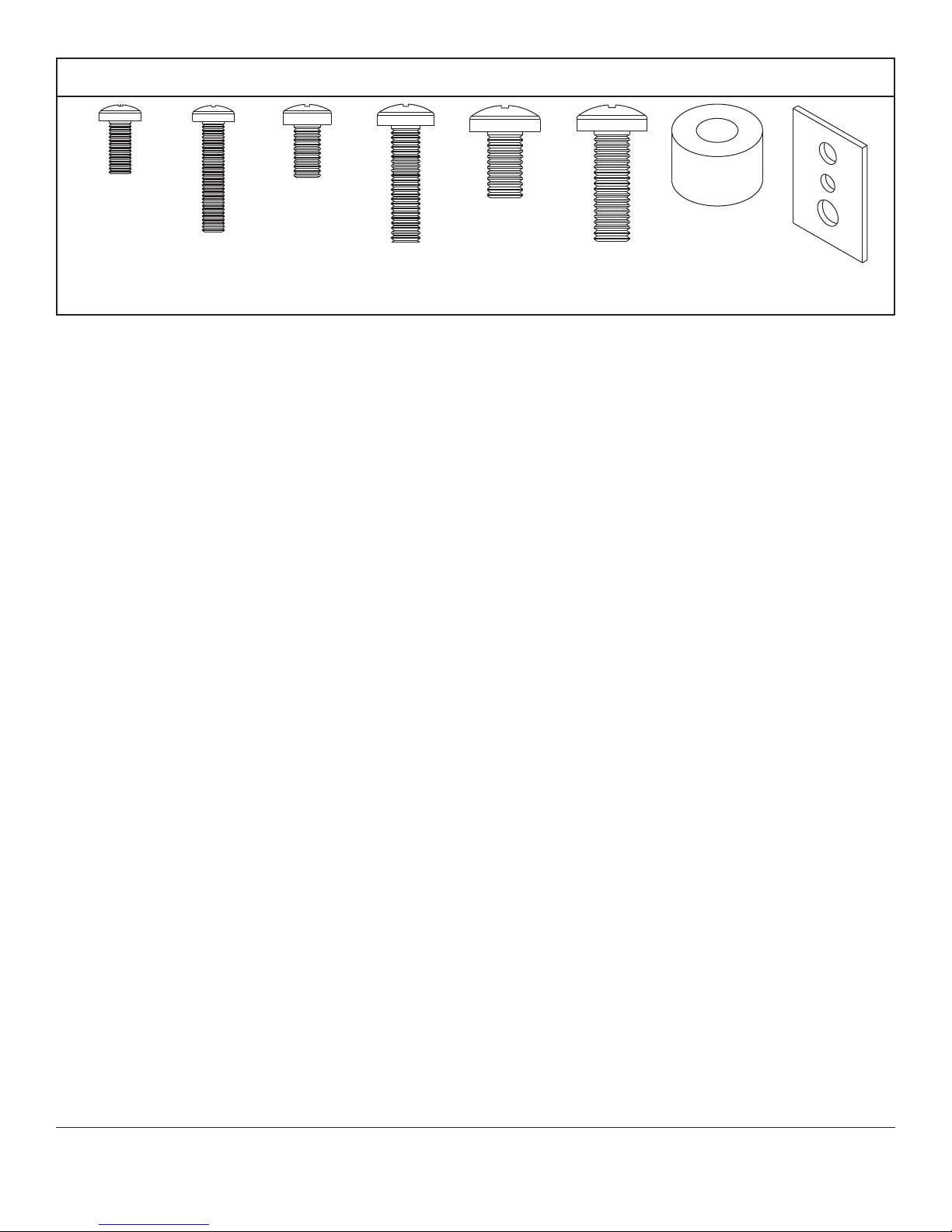
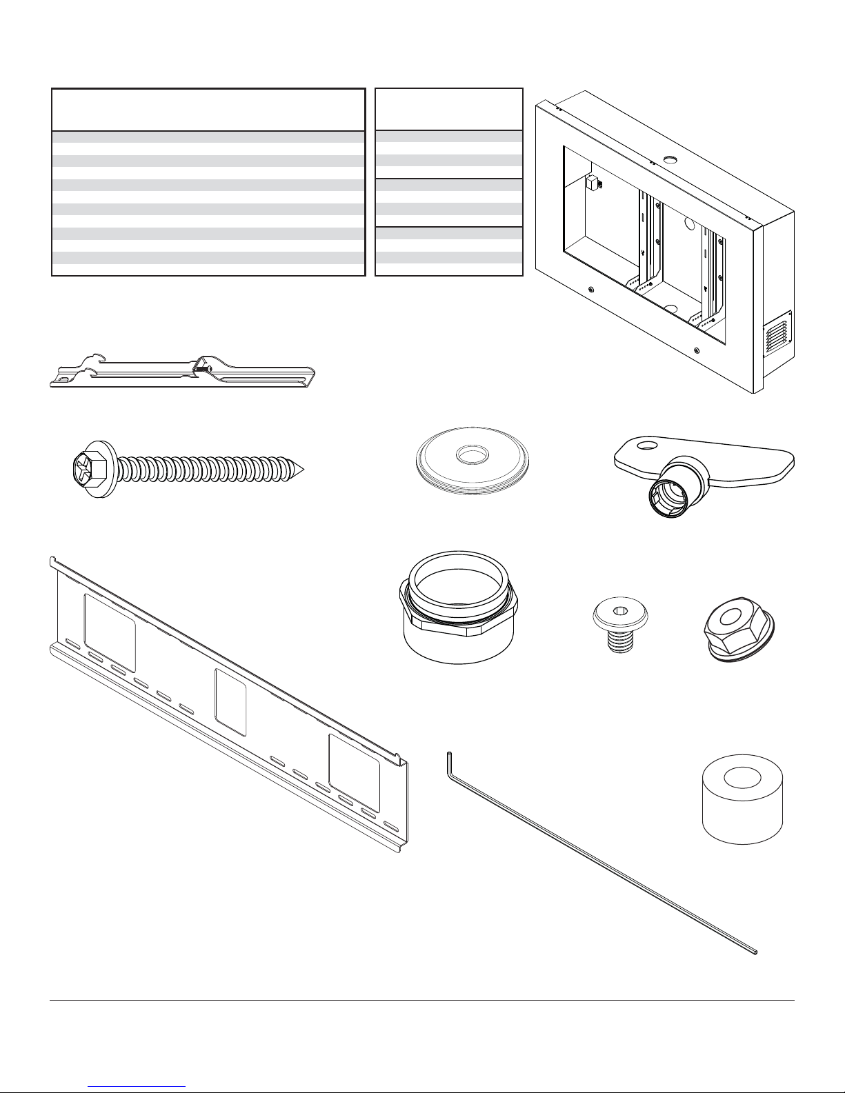
Adapter Bracket Fasteners
M5 x 12 mm (4)
(520-1027)
M5 x 25 mm (4)
(520-9543)
M6 x 12 mm (4)
(520-1128)
M6 x 25 mm (4)
(520-1208)
M8 x 12 mm (4)
(520-9571)
M8 x 25 mm (4)
(520-1031)
.75" spacer (4)
(540-1059)
Multi-washer (4)
(580-1398)
4 of 50
ISSUED: 07-12-10 SHEET #: 061-9056-8 03-05-13
Page 5
Optional Removal of Bay Door
WARNING
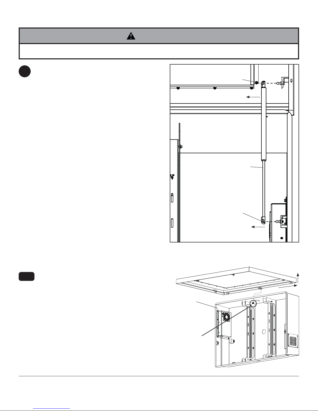
• Grasp bay door fi rmly. Bay door will swing freely when gas springs are removed.
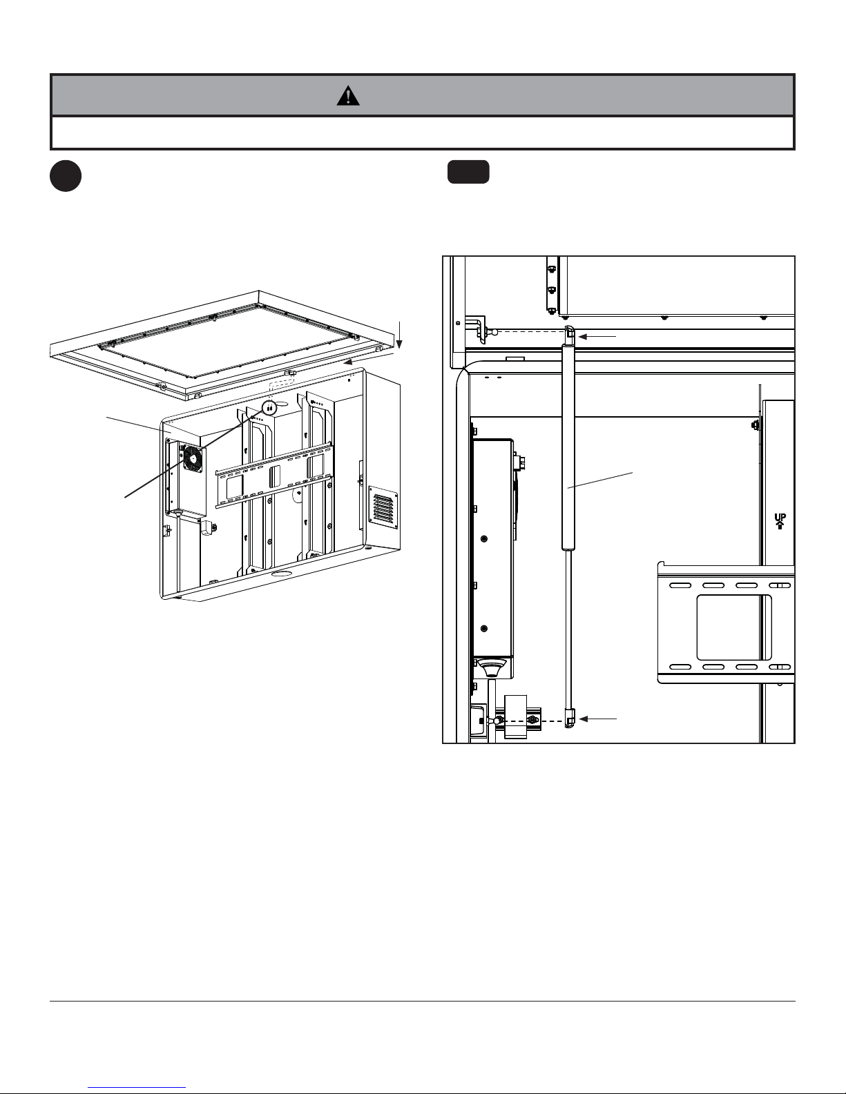
Bay door may be removed for ease of installation
1
to mounting surface. NOTE: Removal of bay door
is optional. Installation may be completed without
removing bay door.
Insert fl athead screwdriver under brass clip of gas
spring shown in detail 1 and pry up. NOTE: Do not
remove brass clip from gas spring. Pull gas spring
away from bay door.
BRASS CLIP
BAY DOOR
MAIN
ENCLOSURE
ASSEMBLY
GAS SPRING
1-1
BRASS CLIP
DETAIL 1
Remove center set of 10-24 x .5" phillips screws
from inside of enclosure assembly (A) as shown in
fi gure 1.1. Slide bay door to the right to disengage
hinges and lift off of enclosure assembly.
A
10-24 x .5"
PHILLIPS SCREWS
5 of 50
fi g. 1.1
ISSUED: 07-12-10 SHEET #: 061-9056-8 03-05-13
Page 6

1-2
Removal of Rear Supports: Remove 3" serrated
washer head screws and locknuts at top and
bottom of rear supports as shown in detail 2 and
lift rear supports out.
LOCKNUT
3" SCREW
REAR SUPPORT
LOCKNUT
DETAIL 2
Installing Cables
Cables may be routed through top, bottom, or rear of main enclosure assembly. An additional available option for
2
cable entry while maintaining the waterproof seal of the enclosure is the ROXTEC cable gland (F).
Install ROXTEC hardware to top, bottom, or rear of enclosure assembly (A). NOTE: If cables are routed through
rear enclosure assembly hole, wall mount is required for mounting to wall.
Follow the ROXTEC manufacturers' instructions for installation included in ROXTEC cable gland (F) box.
Install cord cover plate assembly (K) to remaining open holes of enclosure assembly (A) as shown in detail 3.
3" SCREW
6 of 50
A
K
DETAIL 3
ISSUED: 07-12-10 SHEET #: 061-9056-8 03-05-13
Page 7
Installation to Wood Stud Wall
WARNING
• DO NOT lift more weight than you can handle. Always use an assistant or mechanical lifting equipment to safely lift
and position enclosure assembly (A).
• Installer must verify that the supporting surface will safely support the combined load of the equipment and all
attached hardware and components.
• Tighten wood screws so that the enclosure assembly is fi rmly attached, but do not overtighten. Overtightening can
damage the screws, greatly reducing their holding power.
• Never tighten in excess of 80 in. • lbs. (9 N.M.).
• Make sure that mounting screws are anchored into the center of the stud. The use of an "edge to edge" stud fi nder
is highly recommended.
• Hardware provided is for attachment of mount through standard thickness drywall or plaster into wood studs.
Installers are responsible to provide hardware for other types of mounting situations.
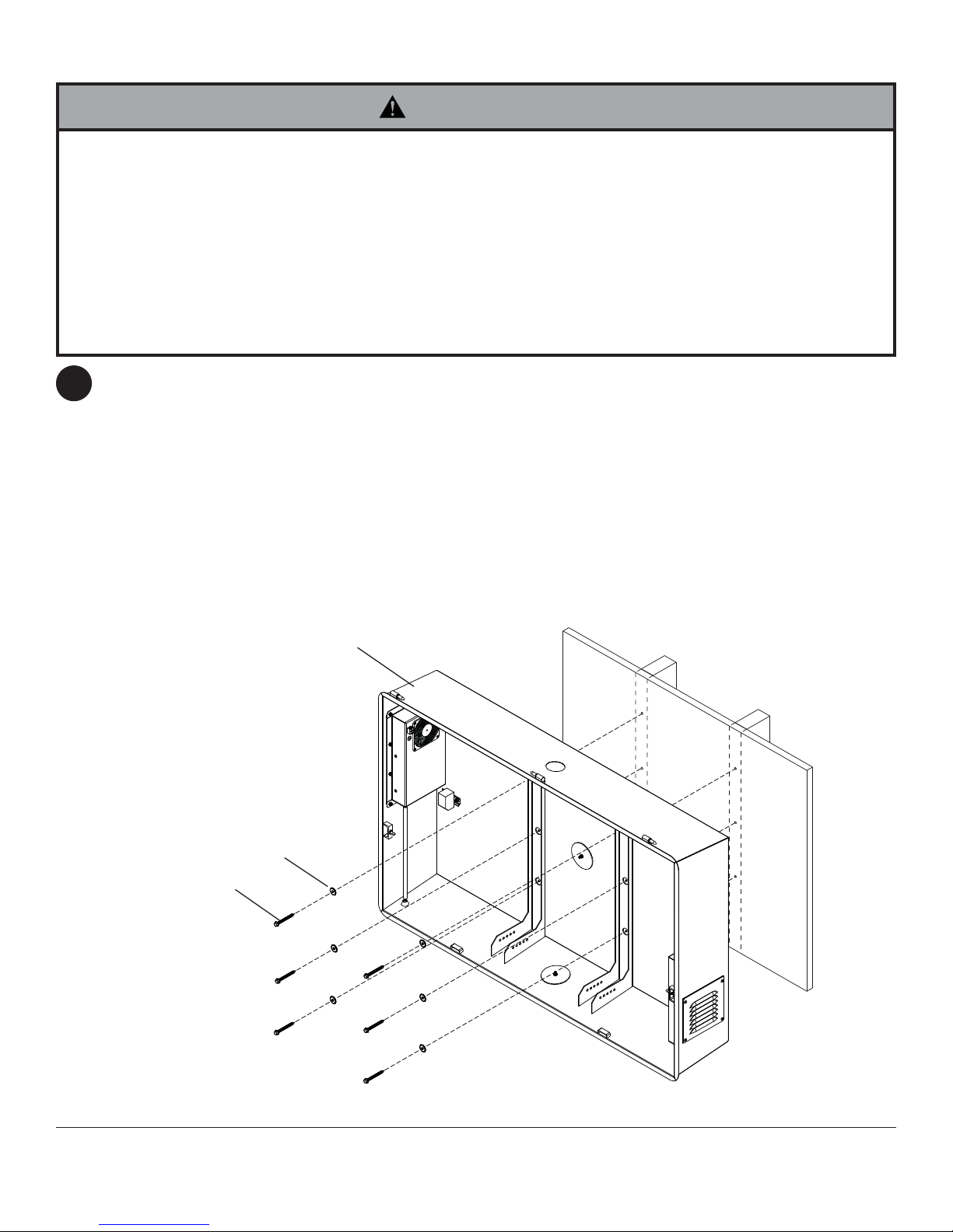
NOTE: This step is for mounting enclosure assembly (A) fl ush against supporting surface. For use with
3
mount, follow instructions provided with wall mount.
Use a stud fi nder to locate the edges of the studs and draw a vertical line down each stud’s center. Place
enclosure assembly (A) on wall as a template, level and mark the center of the six mounting holes. Make sure
that the mounting holes are on the stud centerlines. Drill six 5/32" (4 mm) dia. holes 2.5" (64 mm) deep. Make
sure that the enclosure is level and secure it using six 2.5" wood screws (C) and six washers (E) as shown in
fi gure 3.1.
NOTE: If cord cover plate assembly (K) is used on the rear of the enclosure, you may use the 1/2" spacer (M)
between enclosure assembly and wall surface.
C
E
A
fi g. 3.1
7 of 50
ISSUED: 07-12-10 SHEET #: 061-9056-8 03-05-13
Page 8
Depth Adjustment
WARNING
• Failure to allow this space for air circulation and to allow heat to dissipate from the display may effect the visual appearance and/or cause damage to your display.
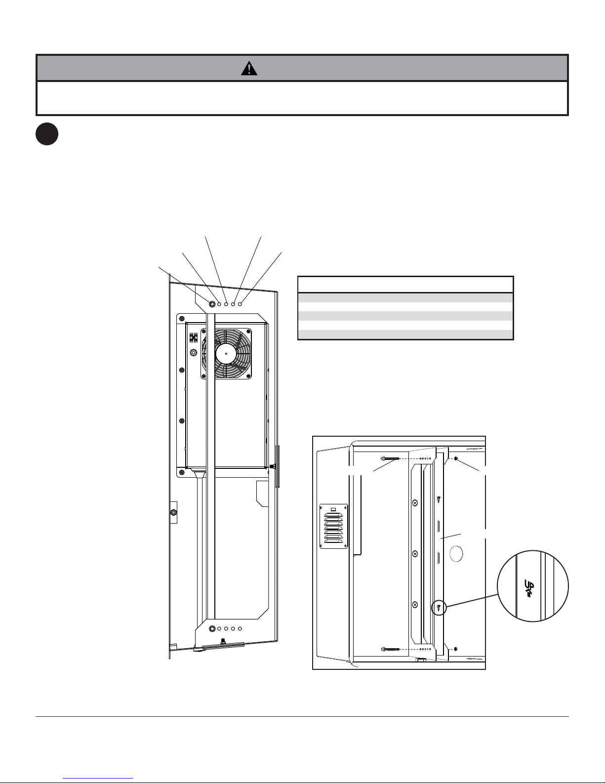
NOTE: The installed display should allow a 1/2" air gap between the front of the display and the interior surface of
4
the window. A display mounted directly against the window will create a dead air space that traps heat which may
affect the funtionality of both the display and the enclosure mount.
Measure the depth of your display. Choose the appropriate fi xed stop-position from the chart below. Reinstall rear
supports with 3" serrated washer head screws and locknuts into appropriate fi xed stop-position as shown in fi gure
4.1. NOTE: Be sure "UP" arrow of rear support is pointing up as shown in fi gure 4.2.
Do not tighten fasteners.
FIXED STOP-POSITION #3 FIXED STOP-POSITION #4
FIXED STOP-POSITION #2
FIXED STOP-POSITION #1
FIXED STOP-POSITION #5
Depth of Display
1-1/8" - 2-1/8" (29 - 54 mm) #1
1-3/4" - 2-3/4" (44 - 70 mm) #2
2-3/8" - 3-3/8" (60 - 86 mm) #3
3" - 4" (76 - 102 mm) #4
3-5/8" - 4-5/8" (92 - 117 mm) #5
3" SCREW
Fixed Stop-Position
REAR SUPPORT
LOCKNUT
fi g. 4.1
8 of 50
fi g. 4.2
ISSUED: 07-12-10 SHEET #: 061-9056-8 03-05-13
Page 9
Wall Plate Installation
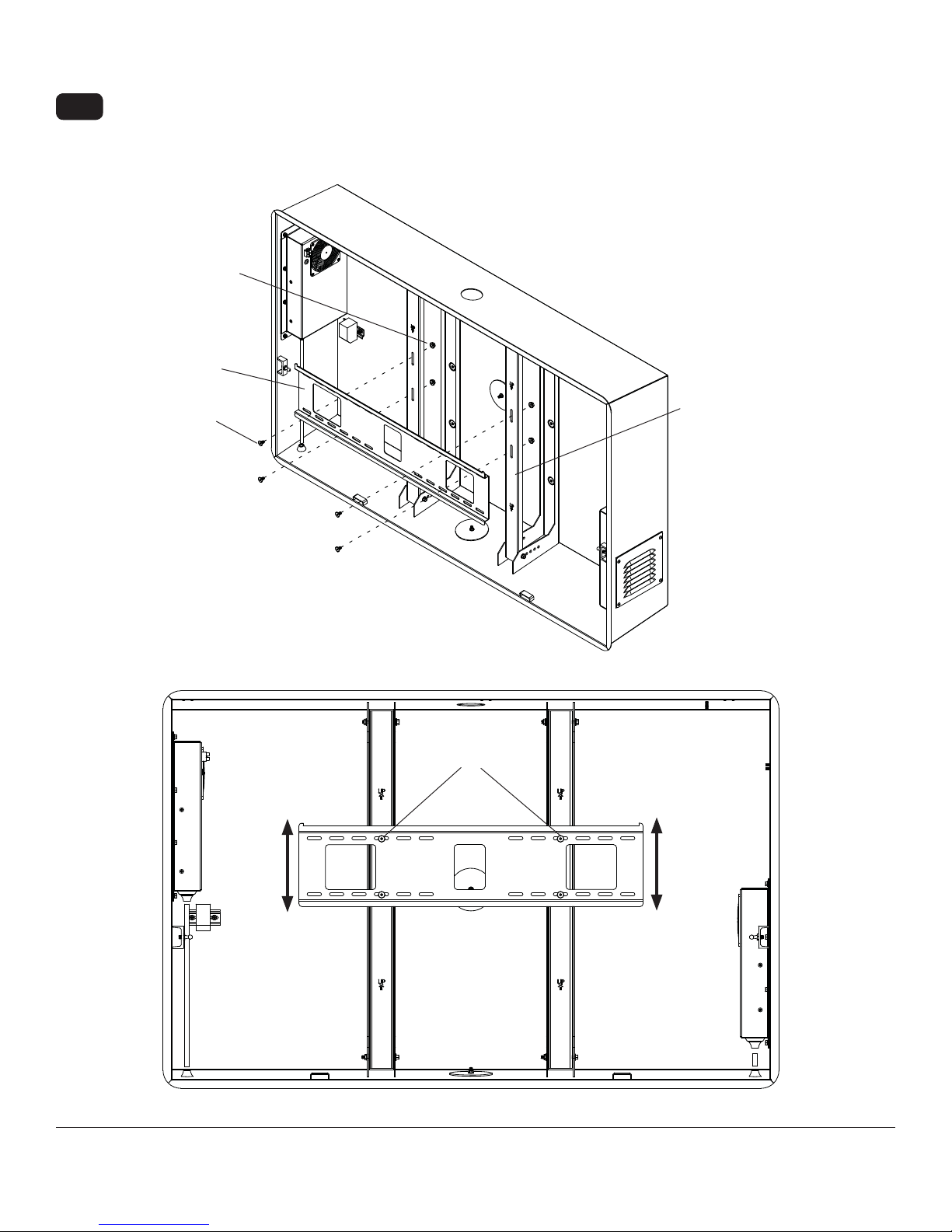
4-1
Attach wall plate (J) to rear supports with four 12 mm fl at head screws (H) and four serrated locknuts (I). Slide
wall plate (J) to desired position (+/- 3/4") vertically.
Level wall plate and tighten 12 mm fl at head screws (H) using 4 mm allen wrench (L).
I
J
REAR SUPPORT
H
H
9 of 50
ISSUED: 07-12-10 SHEET #: 061-9056-8 03-05-13
Page 10
Reinstalling Bay Door
WARNING
• Grasp bay door fi rmly. Bay door will swing freely when gas springs are removed.
If bay door was removed in step 1, lower bay door
5
onto enclosure assembly and slide to the left to
engage hinges. Align holes of center hinge with
holes of enclosure assembly (A). Reinstall two
10-24 x .5" phillips screws to inside of enclosure
assembly as shown in fi gure 5.1.
A
10-24 x .5"
PHILLIPS
SCREWS
5-1
Secure both gas springs to sides of bay door by
pressing on as shown in detail 4.
NOTE: Be sure thin end of gas spring is
attached to main enclosure assembly.
BAY DOOR
MAIN ENCLOSURE
ASSEMBLY
GAS SPRING
fi g. 5.1
DETAIL 4
10 of 50
ISSUED: 07-12-10 SHEET #: 061-9056-8 03-05-13
Page 11
Installing Adapter Brackets
WARNING
• Tighten screws so adapter brackets are fi rmly attached. Do not tighten with excessive force. Overtightening can cause
stress damage to screws, greatly reducing their holding power and possibly causing screw heads to become detached. Tighten to 40 in. • lb (4.5 N.M.) maximum torque.
• If screws don't get three complete turns in the display inserts or if screws bottom out and bracket is still not tightly
secured, damage may occur to display or product may fail.
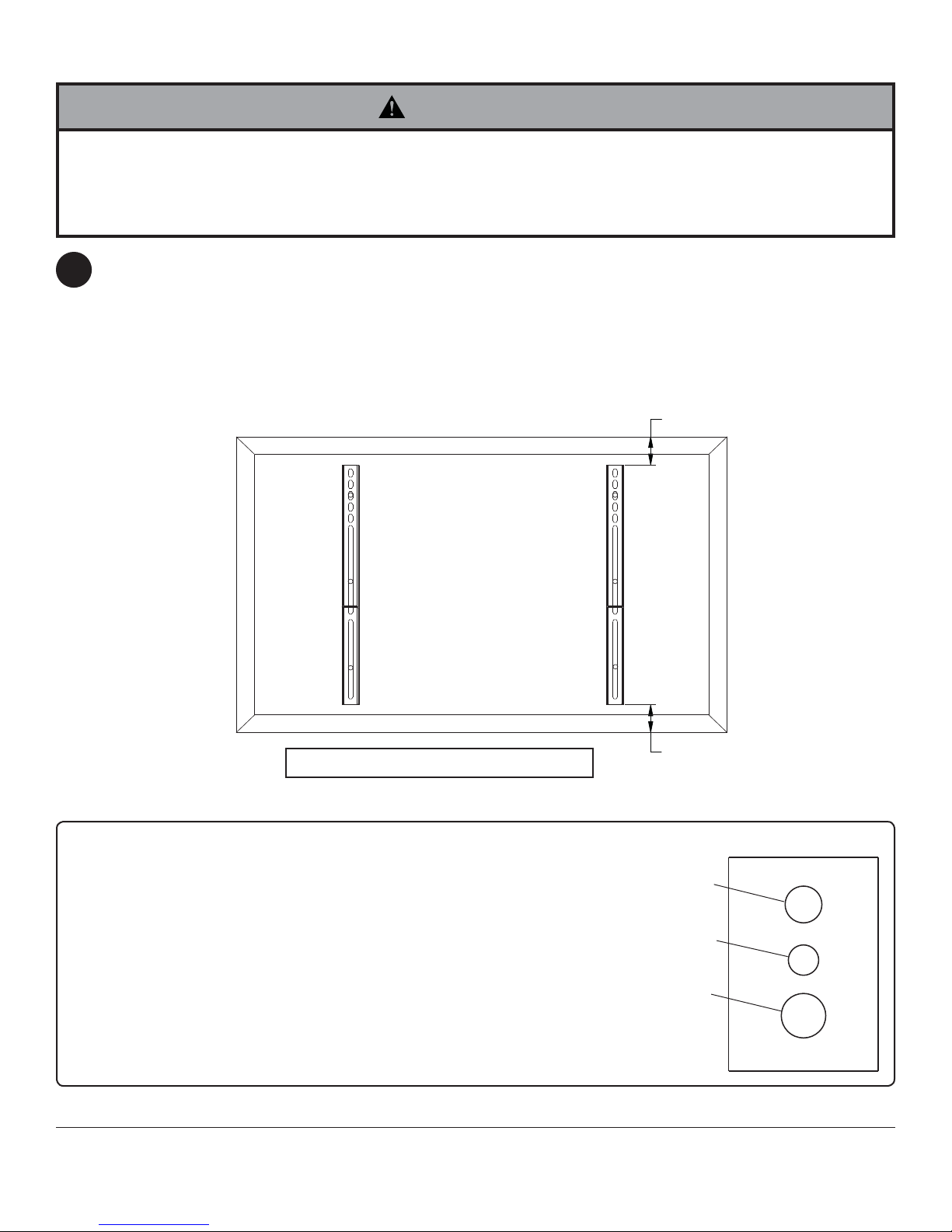
To prevent scratching the display, set a cloth on a fl at, level surface that will support the weight of the display.
6
Place display face side down. If display has knobs on the back, remove them to allow the adapter brackets to be
attached. Place adapter brackets (B) on back of display, align to holes, and center on back of display as shown
below. Attach the adapter brackets to the back of the display using the appropriate combination of screws, multiwashers and spacers as shown in steps 6-1 and 6-2.
NOTE: Top and bottom holes must always be used.
Verify that all holes are properly aligned, and then tighten screws using a phillips screwdriver.
X
CENTER BRACKETS VERTICALL Y
ON BACK OF DISPLAY
B
NOTE: "X" dimensions should be equal.
Notes:
• The number of fasteners used will vary, depending
upon the type of display.
• Multi-washers and spacers may not be used,
depending upon the type of display.
• Use the corresponding hole in the multi-washer
that matches your screw size as shown.
X
MULTI-WASHER
MEDIUM HOLE FOR M5 SCREWS
SMALL HOLE FOR M4 SCREWS
LARGE HOLE FOR M6 SCREWS
11 of 50
ISSUED: 07-12-10 SHEET #: 061-9056-8 03-05-13
Page 12
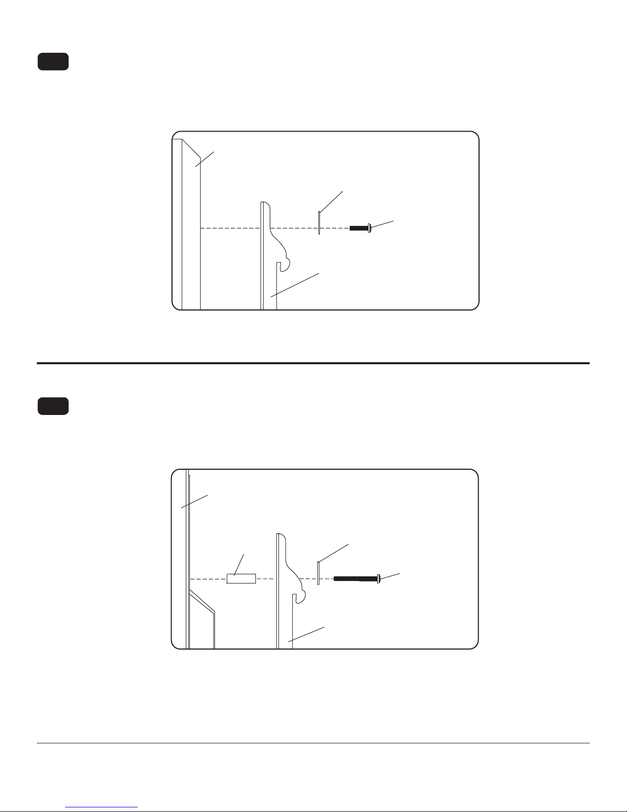
For Flat Back Display
Begin with the shortest length screw, hand thread through multi-washer and adapter bracket into display as
6-1
shown below. Screw must make at least three full turns into the mounting hole and fi t snug into place. Do not
over tighten. If screw cannot make three full turns into the display, select a longer length screw from the baffl ed
fastener pack. Repeat for remaining mounting holes, level brackets and tighten screws.
NOTE: Spacers may not be used, depending upon the type of display.
Display
MULTI-WASHER
SCREW
ADAPTER BRACKET (B)
If you have any questions, please call Peerless customer care at 1-800-865-2112.
For Bump-out or Recessed Back Display
Begin with longer length screw, hand thread through multi-washer, adapter bracket and spacer in that order into
6-2
display as shown below. Screw must make at least three full turns into the mounting hole and fi t snug into place.
Do not over tighten. If screw cannot make three full turns into the display, select a longer length screw from the
baffl ed fastener pack. Repeat for remaining mounting holes, level brackets and tighten screws.
Display
SPACER
MULTI-WASHER
SCREW
ADAPTER BRACKET (B)
If you have any questions, please call Peerless customer care at 1-800-865-2112.
12 of 50
ISSUED: 07-12-10 SHEET #: 061-9056-8 03-05-13
Page 13
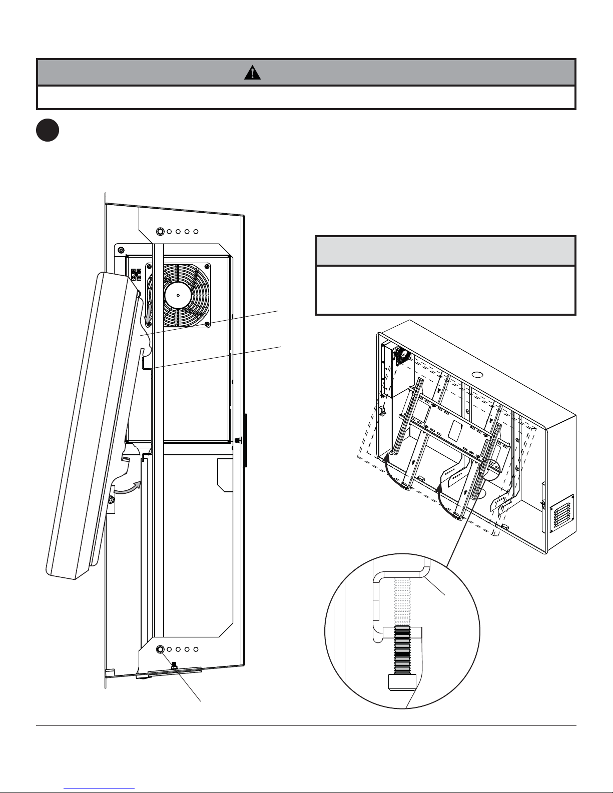
Mounting Flat Panel Display
WARNING
• Always use an assistant or mechanical lifting equipment to safely lift and position the fl at panel displays.
Hook adapter brackets (B) onto wall plate (J) then
7
slowly swing display in as shown in fi gure 7.1.
Remove 3" serrated washer head screws from
bottom of rear supports. Swing rear supports up to
access safety/security screws as shown in fi gure
7.2.
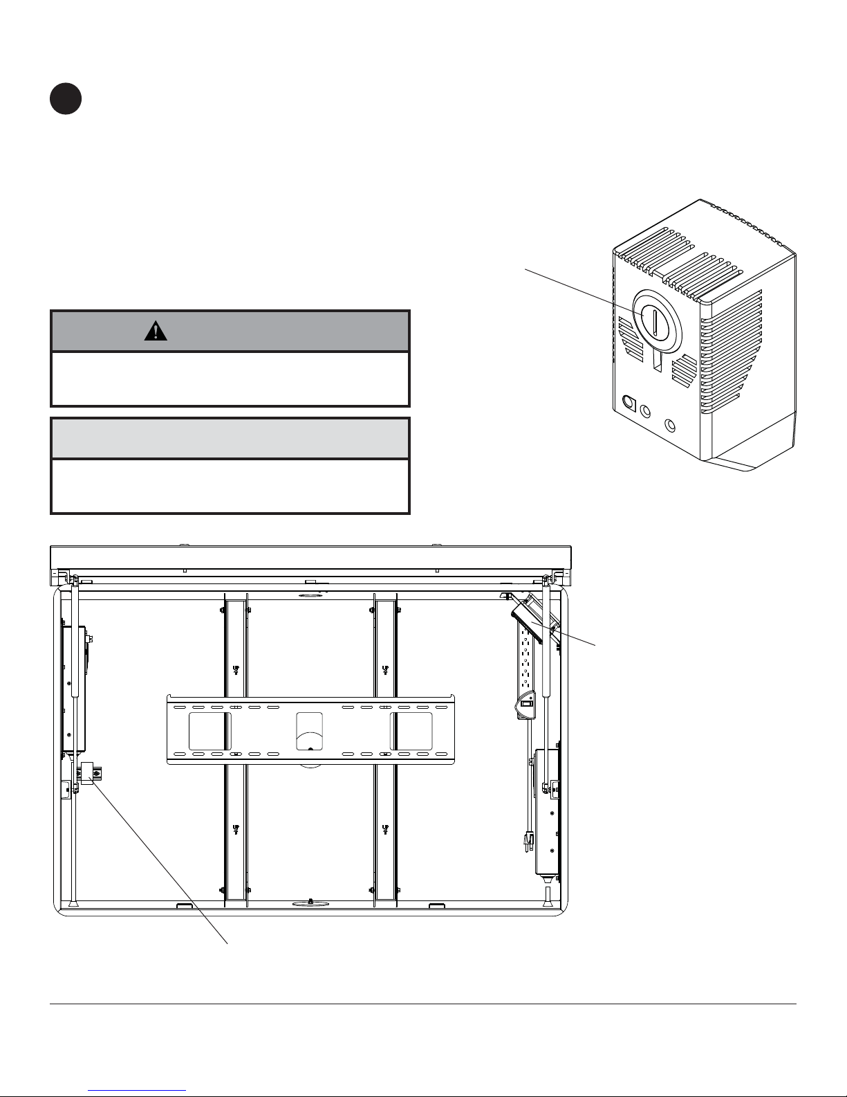
Turn safety/security screws, using 4 mm allen
wrench (L), clockwise at least six times to prevent
display from being removed as shown in detail 5.
NOTE: To lock the display down, tighten safety
screws to wall plate as shown in detail 5.
Route cables through ROXTEC cable seal and plug
into appropriate connection. Reinstall 3" serrated
washer head screws and locknuts to bottom of rear
supports. Tighten all fasteners.
CAUTION
• Do not postion AV and power cables close to heater
or damge to cables may occur. See next page for
more information.
B
J
fi g. 7.1
3" SERRA TED W ASHER
HEAD SCREWS
13 of 50
fi g. 7.2
J
B
DETAIL 5
ISSUED: 07-12-10 SHEET #: 061-9056-8 03-05-13
Page 14
Setting Thermostat
Refer to display manufacturers' requirements for optimal environment temperature. If display manufacturer's
8
requirments state that cooler or warmer temperatures are acceptable, use a fl atblade screwdriver to adjust dial to
desired temperature.
NOTE: Thermostat inside enclosure assembly will determine at what time the Exhaust Fan will initiate. The Intake
Fan will operate at all times. For all other questions, refer to thermostat instruction sheet included in enclosure
assembly.
HEATER INFORMATION (FPE47FH-S,FPE55FH-S only)
Thermostat of heater is not adjustable. The heater will turn
on at 40°±7° and will turn off at 60°±5°.
Heater uses a 20 amp fuse.
DIAL
WARNING
• Frame of heater will be hot when turned on. Turn
heater off allowing frame to cool prior to service.
CAUTION
• Do not postion AV and power cables close to heater
or damge to cables may occur.
HEATER
THERMOSTAT
14 of 50
ISSUED: 07-12-10 SHEET #: 061-9056-8 03-05-13
Page 15
Locking Environmental Enclosure
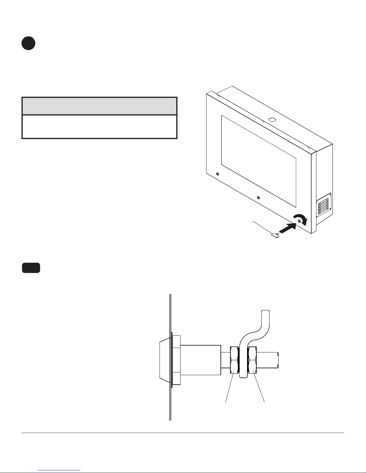
Gently lower bay door. Using key (G) rotate door locks clockwise until key cannot turn. Make sure that the key has
9
fully rotated to seal enclosure. If key does not fully rotate, door lock may need to be adjusted for a looser seal. See
step 9-1 below for door lock adjustment.
NOTE: Gasket seal of bay door must be fully compressed to allow for a water tight seal. Test seal of door by
inserting a sheet of paper in between the door seal and the enclsosure seal. If the sheet of paper is easily removed,
door lock may need to be adjusted for a tighter seal. See step 9-1 below for door lock adjustment.
CAUTION
• Be careful not to pinch your fi ngers when opening and
closing bay door.
NUMBER OF LOCKS
ON DOOR MAY VARY
FROM ILLUSTRATION
Door Lock Adjustment
To allow for a tighter seal, loosen top nut of door locks 1/4" then tighten bottom nut of door locks against lock tab.
9-1
To allow for a more loose seal, loosen bottom nut of door locks 1/4" then tighten top nut of door locks against lock
tab.
FRONT OF BAY DOOR
G
15 of 50
TOP NUT BOTTOM NUT
ISSUED: 07-12-10 SHEET #: 061-9056-8 03-05-13
Page 16

Fan Filter Replacment
Filterfan replacement fi ltermats are sold separately at www.fi lterfanusa.com, for Filterfan model PF 22000.
10
Remove cover from Filterfan on side of enclosure assembly (A) as shown in fi gure 10.1. Remove and replace
fi ltermat as shown in fi gure 10.2.
L
L
U
P
fi g. 10.1
fi g. 10.2
16 of 50
All other brand and product names are trademarks or registered trademarks of their respective owners.
ISSUED: 07-12-10 SHEET #: 061-9056-8 03-05-13
© 2013, Peerless Industries, Inc. All rights reserved.
Page 17

Instalación y Ensamblaje:
S
S
Caja ecológica Peerless para pantallas planas
Nº de Modelos Capacidad máxima de soportar tamaño de la pantalla
FPE47F-S 250 lbs (113 kg) 46"-47"
FPE47FH-S 250 lbs (113 kg) 46"-47"
FPE55F-S 250 lbs (113 kg) 55"
FPE55FH-S 250 lbs (113 kg) 55"
FPE47F-UK-S 250 lbs (113 kg) 46"-47"
FPE47FH-UK-
FPE55F-UK-S 250 lbs (113 kg) 55"
FPE55FH-UKFPE47F-EU-S 250 lbs (113 kg) 46"-47"
FPE47FH-EU-S 250 lbs (113 kg) 46"-47"
FPE55F-EU-S 250 lbs (113 kg) 55"
FPE55FH-EU-S 250 lbs (113 kg) 55"
250 lbs (113 kg) 46"-47"
250 lbs (113 kg) 55"
2300 White Oak Circle • Aurora, Il 60502 • (800) 865-2112 • Fax: (800) 359-6500 • www.peerless-av.com
PUBLICADO: 07-12-10 HOJA#: 061-9056-8 03-05-13
Page 18

Español
NOTA: Lea la hoja de instrucciones completa antes de comenzar la instalación y el ensamblaje.
ADVERTENCIA
• No comience a instalar su producto de Peerless hasta haber leído y entendido las instrucciones y las advertencias contenidas en
la Hoja de Instalación. Si tiene alguna pregunta acerca de cualquiera de las instrucciones o las advertencias, por favor, llame a
Servicio al Cliente de Peerless al 1-800-865-2112 si está en EE. UU. Si es un cliente internacional, por favor, comuníquese con su
distribuidor local.
• Debido a las condiciones ambientales de exteriores como fuertes ráfagas de viento, nieve intensa, granizo, lluvia, etc. La
caja ecológica, junto con su soporte, tubo de extensión y tornillería, se deben inspeccionar cuando menos una vez al año e
inmediatamente después de cualquier ocasión en que los vientos excedan de 90 mph. Un instalador o inspector califi cado deberá
revisar que no haya signos de corrosión, fi jadores sueltos, metal doblado, etc. Si hay señales de desgaste excesivo, deterioro
o cualquier condición insegura, inmediatamente deberá de retirar de servicio este producto. Si tiene alguna pregunta, diríjase al
servicio a clientes.
• Pantallas de vidrio del local deberá evitar la luz solar directa o dañar para el monitor se puede producir.
• Este producto sólo debe ser instalado por una persona que tenga una buena aptitud mecánica, que tenga experiencia en
construcción básica de edifi cios y que entienda estas instrucciones en su totalidad.
• Asegúrese de que la superfi cie de apoyo sostendrá, con seguridad, la carga combinada del equipo y todos los fi jadores y compo-
nentes.
• Nunca sobrepase la capacidad máxima de soportar carga.
• Si va a instalar el producto en una pared con montantes de madera, asegúrese de que los tornillos de montaje estén anclados en
el centro de los montantes. Se recomienda utilizar un localizador de montantes de "borde a borde".
• Siempre cuente con la ayuda de un asistente o utilice un equipo mecánico de izar para levantar y colocar el equipo con más seguridad.
• Apriete los tornillos con fi rmeza, pero no en exceso. Apretarlos en exceso puede dañar los artículos y puede disminuir signifi cati-
vamente su fuerza de fi jación.
• Este producto fue diseñado para su uso con otros productos al aire libre.
• Este producto fue diseñado para ser instalado en paredes con la siguiente construcción solamente:
CONSTRUCCIÓN DE LA PARED ACCESORIOS NECESARIOS
• Montante de madera Incluido
• Viga de madera Incluido
• Concreto macizo Comuníquese con un profesional califi cado
• Bloque de hormigón de escorias Comuníquese con un profesional califi cado
• Ladrillo Comuníquese con un profesional califi cado
• ¿Otra superfi cie o no está seguro? Comuníquese con un profesional califi cado
Vea la página 17.
Herramientas necesarias para el
ensamblaje
• localizador de montantes (se recomienda uno de "borde
a borde")
• taladro
• broca de 5/32" (4 mm) para paredes con montantes de
madera
• nivel
• martillo
• destornillador phillips, llave allen de 5 mm, destornillador
de punta plana
Tabla de contenido
Lista de piezas..................................................................................................................................................................... 19
Retirar la puerta del compartimiento .............................................................................................................................. 21-22
Instalación a la pared .......................................................................................................................................................... 23
Ajuste de profundidad.......................................................................................................................................................... 24
Instalación de la placa de pared .......................................................................................................................................... 25
Reinstalar la puerta ............................................................................................................................................................. 26
Fijar los soportes verticales a la pantalla........................................................................................................................27-28
Montaje de la pantalla ......................................................................................................................................................... 29
Ajuste del termostato ........................................................................................................................................................... 30
Cambio del fi ltro................................................................................................................................................................... 32
18 de 50
PUBLICADO: 07-12-10 HOJA#: 061-9056-8 03-05-13
Page 19

Antes de comenzar, asegúrese de que su producto contiene todas las piezas que se muestran.
o
Las piezas pueden verse un poco distintas a la ilustración.
Español
Lista de piezas
Descripción Cant. Nº de pieza
A unidad de caja 1 ver tabla
soportes adaptadores
B
C tornillos para madera 6 5S1-015-C03
arandelas de sellad
E
F casquillo prensacable ROXTEC 1 600-0107
llave
G
H tornillos de cabeza plana de 12 mm 4 520-2325
contratuercas dentadas
I
J placa de pared 1 201-P1018
K placa de cubierta del cordón (no se muestra) 2 061-7285
L llave Allen de 4 mm 1 560-1727
espaciador de 1/2"
M
2 201-P1513
6 540-4067
1 600-0116
4 530-2021
6 540-1059
B
C
Unidad de Caja (A)
Nº de Modelos
FPE47F-S 061-7327
FPE47FH-S
FPE55F-S 061-7328
FPE55FH-S
FPE47F-UK-S 061-7585
FPE47FH-UK-S
FPE55F-UK-S
FPE55FH-UK-S
FPE47F-EU-S 061-7590
FPE47FH-EU-S 061-7589
FPE55F-EU-S 061-7592
FPE55FH-EU-S
Nº de pieza
061-7564
061-7565
061-7579
061-7586
061-7583
061-7591
E
A
G
J
F
L
H
I
M
19 de 50
PUBLICADO: 07-12-10 HOJA#: 061-9056-8 03-05-13
Page 20

Sujetadores Para Los Soportes Adaptadores
Español
M5 x 12 mm (4)
(520-1027)
M5 x 25 mm (4)
(520-9543)
M6 x 12 mm (4)
(520-1128)
M6 x 25 mm (4)
(520-1208)
M8 x 12 mm (4)
(520-9571)
M8 x 25 mm (4)
(520-1031)
.75" espaciador
(4)
(540-1059)
arandela
múltiple (4)
(580-1398)
20 de 50
PUBLICADO: 07-12-10 HOJA#: 061-9056-8 03-05-13
Page 21

Español
Retiro Opcional de la Puerta del Compartimiento
ADVERTENCIA
• Sujete fi rmemente la puerta del compartimiento. La puerta del compartimiento girará libremente cuando se retiren
los amortiguadores de gas.
Se puede retirar la puerta del compartimiento para
1
facilitar la instalación a la superfi cie de montaje.
NOTA: Retirar la puerta del compartimiento es
opcional. Se puede completar la instalación sin
retirar la puerta del compartimiento.
Inserte un destornillador plano debajo del
clip de latón del amortiguador de gas que se
muestra en el detalle 1 y extráigalo. NOTA: No
retire el clip de latón del amortiguador de gas.
Extraiga el amortiguador de gas de la puerta del
compartimiento.
COMPARTIMIENTO
CLIP DE LATÓN
PUERTA DEL
UNIDAD
DE CAJA
PRINCIPAL
1-1
Retire el juego central de tornillos Phillips de
10-24 x .5" del interior de la unidad de caja (A)
como se muestra en la fi gura 1.1. Deslice la
puerta del compartimiento hacia la derecha para
que salgan las bisagras y levante la unidad de
caja para sacarla.
AMORTIGUADOR
DE GAS
CLIP DE LATÓN
DETALLE 1
A
TORNILLOS PHILLIPS
DE 10-24 x .5"
21 de 50
fi g. 1.1
PUBLICADO: 07-12-10 HOJA#: 061-9056-8 03-05-13
Page 22

1-2
Retiro de los soportes posteriores: Retire los
tornillos de cabeza hueca con arandela dentada
de 3" y las contratuercas en la parte superior
e inferior de los soportes posteriores como se
muestra en el detalle 2 y levante los soportes
posteriores para sacarlos.
CONTRATUERCA
Español
3" TORNILLOS
SOPORTE POSTERIOR
CONTRATUERCA
3" TORNILLOS
DETALLE 2
Instalación de Cables
Los cables se pueden canalizar a través de la parte superior, inferior o trasera de la unidad de caja principal. Una
2
opción adicional existente para la entrada de los cables y a la vez mantener el sello hermético de la caja es el
casquillo prensacable ROXTEC (F).
Instale la tornillería ROXTEC a la parte superior, inferior o trasera de la unidad de caja (A). NOTA: Si se pasan los
cables por el orifi cio trasero de la unidad de caja, se requiere un soporte de pared para montarlo a la pared.
Para la instalación, siga las instrucciones del fabricante de ROXTEC que se incluyen en la caja del casquillo
prensacable ROXTEC (F).
Instale la unidad de la placa de cubierta del cordón
(K) a los orifi cios abiertos restantes de la unidad de
caja (A) como se muestra en el detalle 3.
22 de 50
A
K
DETALLE 3
PUBLICADO: 07-12-10 HOJA#: 061-9056-8 03-05-13
Page 23

Español
Instalación en una pared con montantes de madera
ADVERTENCIA
• NO levante más peso del que pueda manipular. Utilice siempre un asistente o equipo mecánico de izar para levantar con seguridad y colocar la unidad de caja (A).
• El instalador tiene que asegurarse de que la superfi cie de apoyo sostendrá, con seguridad, la carga combinada del
equipo y todos los fi jadores y componentes.
• Apriete los tornillos de madera de manera que la placa de pared se fi je fi rmemente, pero no en exceso. Apretar los
en exceso puede dañar los tornillos y puede disminuir signifi cativamente su fuerza de fi jación.
• Nunca apriete a más de 80 pulg-lb (9 N•m).
• Asegúrese de que los tornillos de montaje estén anclados en el centro del montante. Se recomienda utilizar un
localizador de montantes de "borde a borde".
• Los accesorios para la instalación que se proveen son para fi jar el soporte a montantes de madera a través de
tabique de yeso-cartón o yeso de espesor estándar. Los instaladores son responsables de suministrar los accesorios necesarios para otros tipos de instalaciones.
NOTA: Este paso es para montar la unidad de caja (A) empotrada contra una superfi cie de apoyo. Para
3
usarse con soporte, siga las instrucciones provistas con el soporte de pared.
Utilice un localizador de montantes para localizar los bordes de los montantes y trace una línea vertical por el
centro de cada montante. Coloque la unidad de caja (A) sobre la pared como plantilla, nivele y marque el centro
de los seis agujeros de montaje. Asegúrese de que los agujeros de montaje estén sobre las líneas que trazó por
el centro de los montantes. Taladre seis agujeros de 5/32" (4 mm) de diámetro y 2.5" (64 mm) de profundidad.
Asegúrese de que la caja esté nivelada y fíjela usando seis tornillos para madera de 2.5" (C) y seis arandelas (E)
como se muestra en la fi gura 3.1.
NOTA: Si se usa una unidad de placa de cubierta del cordón (K) en la parte trasera de la caja, se puede usar el
espaciador de 1/2" (M) entre la unidad de caja y la superfi cie del muro.
C
E
A
fi g. 3.1
23 de 50
PUBLICADO: 07-12-10 HOJA#: 061-9056-8 03-05-13
Page 24

Español
Ajuste de Profundidad
ADVERTENCIA
• Si no deja este espacio para la circulación del aire y permitir que se disipe el calor de la pantalla, se puede afectar
la apariencia visual de su pantalla y/o provocar daños a la misma.
NOTA: La pantalla instalada debe contar con 1/2" de separación de aire entre el frente de la pantalla y la
4
superfi cie interior de la ventana. Una pantalla que se monta directamente contra la ventana creará un espacio de
aire muerto que atrapa el calor y puede afectar la funcionalidad tanto de la pantalla como del montante de la caja.
Mida la profundidad de su pantalla. Escoja en la siguiente tabla la posición fi ja de descanso adecuada. Reinstale
los soportes posteriores con tornillos de cabeza hueca con arandela dentada de 3" y contratuercas en la posición
fi ja de descanso adecuada como se muestra en la fi gura 4.1. NOTA: Compruebe que la fl echa "UP" del soporte
posterior apunte hacia arriba como se muestra en la fi gura 4.2.
No apriete los fi jadores.
POSICIÓN FIJA DE DESCANSO #3 POSICIÓN FIJA DE DESCANSO #4
POSICIÓN FIJA DE DESCANSO #2
POSICIÓN FIJA DE DESCANSO #1
POSICIÓN FIJA DE DESCANSO #5
POSICIÓN FIJA DE
PROFUNDIDAD DE LA PANTALLA
1-1/8" - 2-1/8" (29 - 54 mm) #1
1-3/4" - 2-3/4" (44 - 70 mm) #2
2-3/8" - 3-3/8" (60 - 86 mm) #3
3" - 4" (76 - 102 mm) #4
3-5/8" - 4-5/8" (92 - 117 mm) #5
DESCANSO
fi g. 4.1
24 de 50
3" TORNILLOS
PUBLICADO: 07-12-10 HOJA#: 061-9056-8 03-05-13
CONTRATUERCA
SOPORTE POSTERIOR
fi g. 4.2
Page 25

Instalación de la Placa de Pared
Español
4-1
Fije la placa de pared (J) a los soportes posteriores con cuatro tornillos de cabeza plana de 12 mm (H) y cuatro
contratuercas dentadas (I). Deslice verticalmente la placa de pared (J) a la posición deseada (+/- 3/4").
Nivele la placa de pared y apriete los tornillos de cabeza plana de 12 mm (H) con una llave Allen de 4 mm (L).
I
J
SOPORTE POSTERIOR
H
H
25 de 50
PUBLICADO: 07-12-10 HOJA#: 061-9056-8 03-05-13
Page 26

Español
Reinstalación de la puerta del compartimiento
ADVERTENCIA
• Sujete fi rmemente la puerta del compartimiento. La puerta del compartimiento girará libremente cuando se retiren
los amortiguadores de gas.
Si en el paso 1 retiró la puerta del compartimiento,
5
baje la puerta del compartimiento a la unidad de
caja y deslícela a la izquierda para que entren
las bisagras. Alinee los orifi cios de la bisagra del
centro con los orifi cios de la unidad de caja (A).
Reinstale dos tornillos Phillips de 10-24 x .5" en
la parte interior de la unidad de caja como se
muestra en la fi gura 5.1.
A
TORNILLOS
PHILLIPS DE
10-24 x .5"
5-1
Fije ambos amortiguadores de gas a los
costados de la puerta del compartimiento,
presionando como se muestra en el detalle 4.
NOTA: Asegúrese de que el extremo delgado
del amortiguador de gas quede fi jo a la puerta
del compartimiento.
PUERTA DEL
COMPARTIMIENTO
UNIDAD DE CAJA
PRINCIPAL
AMORTIGUADOR
DE GAS
fi g. 5.1
26 de 50
DETALLE 4
PUBLICADO: 07-12-10 HOJA#: 061-9056-8 03-05-13
Page 27

Instalación de los soportes adaptadores
ADVERTENCIA
• Apriete los tornillos de manera que los soportes adaptadores se fi jen con fi rmeza. No los apriete con
fuerza excesiva. Apretar los tornillos en exceso puede causarles daño por forzarlos y puede disminuir
signifi cativamente su fuerza de fi jación y podría causar el desprendimiento de las cabezas de los tornillos.
Apriete los tornillos a un máximo de 40 pulg-lb (4.5 N•m) de par torsor.
• Si no se les da tres vueltas completas a los tornillos en los insertos de la pantalla o si los tornillos topan fondo
y el soporte todavía no está fi rme, se podría dañar la pantalla o el producto podría no funcionar bien.
Para no rayar la pantalla, coloque un trapo sobre una superfi cie plana y nivelada que sostenga el peso de la pan-
6
talla. Coloque la pantalla boca abajo. Si la pantalla tiene perillas en la parte trasera, quíteselas para poder fi jar los
soportes adaptadores.
Coloque los soportes adaptadores (B) en la parte trasera de la pantalla, alinéelos con los agujeros y centralícelos
en la parte trasera de la pantalla, como se muestra abajo. Fije los soportes adaptadores en la parte trasera de la
pantalla utilizando la combinación adecuada de tornillos, arandelas múltiples y espaciadores, como se muestra en
la paso 6-1 o en el paso 6-2.
NOTA: Siempre se tienen que usar los agujeros superiores y los agujeros inferiores de la pantalla.
Verifi que que todos los agujeros estén debidamente alineados y luego apriete los tornillos usando un destornillador
phillips.
X
Español
ARANDELA MÚLTIPLE
CENTRALICE
LOS SOPORTES
VERTICALMENTE
B
EN LA PARTE
TRASERA DE LA
PANTALLA
X
NOTA: LAS DIMENSIONES "X" DEBEN SER IGUALES.
NOTAS:
AGUJERO MEDIANO PARA TORNILLOS M5
AGUJERO PEQUEÑO PARA TORNILLOS M4
AGUJERO GRANDE PARA TORNILLOS M6
• El número de sujetadores que se
utilizará variará, dependiendo del tipo
de pantalla.
• Es posible que no necesite las
arandelas múltiples y los espaciadores,
dependiendo del tipo de pantalla.
• Utilice el agujero correspondiente de la
arandela múltiple que sea del mismo
tamaño del tornillo.
NOTA: En el caso de los televisores que tienen la parte posterior plana, pase al paso 6-1. En el caso de los televisores
que tienen la parte posterior abultada o empotrada, pase al paso 6-2.
27 de 50
PUBLICADO: 07-12-10 HOJA#: 061-9056-8 03-05-13
Page 28

Instalación de un televisor que tiene la parte posterior plana
Comience con uno de los tornillos más cortos, enrósquelo, con la mano, a través de la arandela múltiple y el
6-1
soporte adaptador (B) a la parte posterior de la pantalla, como se muestra abajo. El tornillo tiene que dar, por lo
menos, tres vueltas completas dentro del agujero de montaje y debe quedar ajustado en su lugar. No apriete los
tornillos en exceso. Si el tornillo no puede dar tres vueltas completas al entrar en la parte posterior de la pantalla,
seleccione un tornillo más largo de los sujetadores identifi cados y clasifi cados en las divisiones del empaque
plástico. Siga el mismo procedimiento con los agujeros de instalación restantes, nivele los soportes y apriete los
tornillos.
NOTA: Es posible que no necesite usar los espaciadores, dependiendo del tipo de pantalla.
PANTALLA
ARANDELA MÚLTIPLE
TORNILLOS
SOPORTE ADAPT ADOR (B)
Español
Si tiene alguna pregunta, por favor, llame a Servicio al Cliente de Peerless al 1-800-865-2112.
Instalación de un televisor que tiene la parte posterior abultada o empotrada
Comience con uno de los tornillos más largos, enrósquelo, con la mano, a través de la arandela múltiple, el
6-2
soporte adaptador (B) y el espaciador, en ese orden, a la parte posterior de la pantalla, como se muestra abajo.
El tornillo tiene que dar, por lo menos, tres vueltas completas dentro del agujero de montaje y debe quedar
ajustado en su lugar. No apriete los tornillos en exceso. Si el tornillo no puede dar tres vueltas completas al entrar
en la parte posterior de la pantalla, seleccione un tornillo más largo de los sujetadores identifi cados y clasifi cados
en las divisiones del empaque plástico. Siga el mismo procedimiento con los agujeros de instalación restantes,
nivele los soportes y apriete los tornillos.
PANTALLA
ESPACIADOR
ARANDELA MÚLTIPLE
TORNILLOS
Si tiene alguna pregunta, por favor, llame a Servicio al Cliente de Peerless al 1-800-865-2112.
SOPORTE ADAPT ADOR (B)
28 de 50
PUBLICADO: 07-12-10 HOJA#: 061-9056-8 03-05-13
Page 29

Instalación de la Pantalla Plana
ADVERTENCIA
• Siempre cuente con un asistente o con un equipo mecánico de izar para levantar y colocar los televisores de
pantalla plana con más seguridad.
Español
Enganche los soportes adaptadores (B) en la placa
7
de pared (J) y luego gire la pantalla lentamente
hacia dentro, como se muestra en la fi gura 7.1.
Retire los tornillos de cabeza hueca con arandela
dentada de 3" de la parte inferior de los soportes
posteriores. Gire hacia arriba los soportes
posteriores para tener acceso a los tornillos de
seguridad como se muestra en la fi gura 7.2.
B
J
Usando una llave Allen de 4 mm (L), gire a la
derecha los tornillos de seguridad cuando menos
seis veces para evitar que se retire la pantalla como
se muestra en el detalle 5. NOTA: Para trabar la
pantalla, apriete los tornillos de seguridad a la placa
de pared, como se muestra en el detalle 5.
Pase los cables por sello de cables ROXTEC y
enchufe en la conexión adecuada. Reinstale los
tornillos de cabeza hueca con arandela dentada
de 3" y las contratuercas a la parte inferior de los
soportes posteriores. Apriete todos los fi jadores.
PRECAUCIÓN
• No coloque los cables audio/vídeo y los cables de
alimentación cerca de la calefacción o daños a los
cables se puede producir. Véase la página siguiente
para más información.
TORNILLOS DE CABEZA HUECA
fi g. 7.1
CON ARANDELA DENTADA DE 3"
29 de 50
fi g. 7.2
J
B
DETALLE 5
PUBLICADO: 07-12-10 HOJA#: 061-9056-8 03-05-13
Page 30

Ajuste del Termostato
Consulte los requerimientos de la temperatura ambiental óptima con el fabricante de la pantalla. Si los
8
requerimientos del fabricante de la pantalla indican que son aceptables las temperaturas más frescas o más
calientes, use un destornillador de pala para ajustar la carátula a la temperatura deseada.
NOTA: El termostato dentro de la unidad de caja determinará en qué momento se activa el extractor. El ventilador
de admisión funcionará en todo momento. Si tiene alguna pregunta, consulte la hoja de instrucciones del
termostato que se incluye con la unidad de caja.
INFORMACIÓN DEL CALENTADOR (solamente
FPE47FH-S,FPE55FH-S)
El termostato del calentador no es ajustable. El calentador
se encenderá a 40°±7° y se apagará a 60°±5°.
El calentador usa un fusible de 20 amp.
CARÁTULA
ADVERTENCIA
• Marco del calentador se calienta cuando está encendido. Apagar el calentador que permite el marco
para enfriar antes del servicio.
Español
PRECAUCIÓN
• No coloque los cables audio/vídeo y los cables de
alimentación cerca de la calefacción o daños a los
cables se puede producir.
CALENTADOR
TERMOSTATO
30 de 50
PUBLICADO: 07-12-10 HOJA#: 061-9056-8 03-05-13
Page 31

Bloqueo de la Caja Ecológica
Suavemente baje la puerta del compartimiento. Use una llave (G) para girar a la derecha las cerraduras de la
9
puerta hasta que no de vuelta la llave. Compruebe que la llave haya dado vuelta completamente para sellar la caja.
Si la llave no da vuelta completamente, es posible que sea necesario ajustar la cerradura de la puerta para que el
sello quede más suelto. Vea más adelante el paso 9-1 para el ajuste de la cerradura de la puerta.
NOTA: La junta de sellado de la puerta del compartimiento debe estar bien comprimida para permitir que quede
hermético. Pruebe el sello de la puerta insertando una hoja de papel entre el sello de la puerta y el sello de la caja.
Si puede retirar fácilmente la hoja, es posible que necesite ajustar la cerradura de la puerta para que quede bien
sellada. Vea más adelante el paso 9-1 para el ajuste de la cerradura de la puerta.
PRECAUCIÓN
• Tenga cuidado de no pillarse los dedos al abrir y
cerrar puerta de la bahía.
Español
EL NUMERO DE CERRADURAS
EN LA PUERTA PUEDE SER
DIFERENTE A LA ILUSTRACIÓN
Ajuste de la cerradura de la puerta
Para permitir un sello más ajustado, afl oje la tuerca superior de las cerraduras de la puerta 1/4" y luego apriete la
9-1
tuerca inferior de las cerraduras de la puerta contra la lengüeta trabadora.
Para permitir un sello más fl ojo, afl oje la tuerca inferior de las cerraduras de la puerta 1/4" y luego apriete la
tuerca superior de las cerraduras de la puerta contra la lengüeta trabadora.
FRENTE DE LA PUERTA DEL
COMPARTIMIENTO
G
TUERCA SUPERIOR TUERCA INFERIOR
31 de 50
PUBLICADO: 07-12-10 HOJA#: 061-9056-8 03-05-13
Page 32

Cambio del fi ltro del ventilador
Los fi ltros para reemplazo del Filterfan se venden por separado en www.fi lterfanusa.com, para el modelo PF 22000
10
de Filterfan.
Retire la cubierta del Filterfan del lado de la unidad de caja (A) como se muestra en la fi gura 10.1. Retire y cambie
el fi ltro como se muestra en la fi gura 10.2.
L
L
U
P
Español
fi g. 10.1
fi g. 10.2
32 de 50
Cualesquiera otras marcas y nombres de productos son marcas comerciales o registradas de sus respectivos dueños.
PUBLICADO: 07-12-10 HOJA#: 061-9056-8 03-05-13
© 2013, Peerless Industries, Inc. Todos los derechos reservados.
Page 33

Installation et montage :
S
S
Enceinte de Protection Peerless pour Écrans Plats
Modèles nº Capacité de charge maximale Taille de l'écran
FPE47F-S 250 lbs (113 kg) 46 - 47 po
FPE47FH-S 250 lbs (113 kg) 46 - 47 po
FPE55F-S 250 lbs (113 kg) 55 po
FPE55FH-S 250 lbs (113 kg) 55 po
FPE47F-UK-S 250 lbs (113 kg) 46 - 47 po
FPE47FH-UKFPE55F-UK-S 250 lbs (113 kg) 55 po
FPE55FH-UKFPE47F-EU-S 250 lbs (113 kg) 46 - 47 po
FPE47FH-EU-S 250 lbs (113 kg) 46 - 47 po
FPE55F-EU-S 250 lbs (113 kg) 55 po
FPE55FH-EU-S 250 lbs (113 kg) 55 po
250 lbs (113 kg) 46 - 47 po
250 lbs (113 kg) 55 po
2300 White Oak Circle • Aurora, Il 60502 • (800) 865-2112 • Fax: (800) 359-6500 • www.peerless-av.com
PUBLIÉ LE: 07-12-10 FEUILLE no: 061-9056-8 03-05-13
Page 34

Français
REMARQUE: lisez entièrement la fi che d’instructions avant de commencer l’installation et l’assemblage.
AVERTISSEMENT
• Ne commencez pas à installer votre produit Peerless avant d’avoir lu et assimilé les instructions et les avertissements contenus
dans cette fi che d’installation. Pour toute question concernant les instructions ou les avertissements, veuillez appeler le service à
la clientèle de Peerless au 1-800-865-2112; tous les clients internationaux sont priés de contacter leur distributeur local.
• En raison des conditions de température extérieure telles que vents forts, neige abondante, grêle, pluie, etc. l'enceinte de
protection, ainsi que son support, son tube de rallonge et ses pièces de fi xation, doivent être inspectés au moins une fois par
année et immédiatement après des vents de plus de 90 mi/h (145 km/h) Un installateur ou un inspecteur qualifi é doit vérifi er
les signes de rouille, de fi xations desserrées, de métal tordu, etc. Si l'inspection révèle une usure excessive, une détérioration
ou un danger quelconque, ce produit doit être mis hors service immédiatement. Pour toute question, veuillez vous adresser au
service à la clientèle.
• Écrans de verre de l'enceinte doit éviter les rayons directs du soleil ou des dommages à d'affi chage peuvent se produire.
• Ce produit doit être installé uniquement par quelqu’un possédant une bonne aptitude à la mécanique, une expérience de la
construction immobilière et ayant bien compris ces instructions.
• Assurez-vous que la surface de support puisse soutenir sans danger la charge totale de l’équipement ainsi que des pièces et composants qui y sont attachés.
• Ne dépassez jamais la capacité de charge maximum. Reportez-vous à la page 33.
• Lors d’une installation sur un mur à montants en bois, assurez-vous que les vis de montage sont ancrées au centre des montants.
L’utilisation d’un localisateur de montants « bord à bord » est fortement recommandée.
• Pour lever et positionner l’équipement en toute sécurité, faites-vous toujours aider par une autre personne ou utilisez un dispositif
de levage mécanique.
• Serrez fermement les vis, mais sans excès. Un serrage excessif peut endommager les composants et en réduire considérablement la capacité de support.
• Ce produit a été conçu pour être utilisé avec d'autres produits à l'extérieur uniquement.
• Ce produit a été conçu uniquement pour une installation sur les types de murs ci-dessous :
TYPE DE MUR PIÈCES DE FIXATION REQUISES
• Montant en bois Incluses
• Poutre en bois Incluses
• Béton plein Contacter un professionnel qualifi é
• Bloc de béton de mâchefer Contacter un professionnel qualifi é
• Brique Contacter un professionnel qualifi é
• Autre, ou vous n’êtes pas sûr ? Contacter un professionnel qualifi é
Outils nécessaires au montage
• localisateur de montants (un localisateur de montants
« bord à bord » est recommandé)
• perceuse
• tournevis phillips, Clé Allen de 5 mm, tournevis à tête plate
• foret de 5/32 po (4 mm) pour les murs à montants en bois
• niveau
• marteau
Table des matières
Liste des pièces .............................................................................................................................................................. 35-36
Retrait de la porte de baie ................................................................................................................................................... 37
Installation au mur ............................................................................................................................................................... 39
Réglage de la profondeur .................................................................................................................................................... 40
Installation de la plaque murale ........................................................................................................................................... 41
Réinstallation de la porte ..................................................................................................................................................... 42
Fixation des supports verticaux à l'écran ......................................................................................................................43-44
Montage de l’écran .............................................................................................................................................................. 45
Réglage du thermostat ........................................................................................................................................................ 46
Remplacement du fi ltre........................................................................................................................................................ 48
34 sur 50
PUBLIÉ LE: 07-12-10 FEUILLE no: 061-9056-8 03-05-13
Page 35

Avant de commencer, veillez à ce que toutes les pièces énumérées soient incluses.
s
e
)
o
Les pièces peuvent différer légèrement de l’illustration.
Français
Liste des pièces
Description Qté Pièce nº
A montage de l'enceinte 1 voir table
B supports adaptateurs 2 201-P1513
C vis à bois 6 5S1-015-C03
rondelles étanche
E
F goupille de câble ROXTEC 1 600-0107
clé
G
H vis à tête plate de 12 mm 4 520-2325
écrous de blocage à embase cranté
I
J plaque murale 1 201-P1018
plaque du cache-câbles (pas démontré
K
L clé hexagonale de 4 mm 1 560-1727
l'entretoise de 1/2 p
M
6 540-4067
1 600-0116
4 530-2021
2 061-7285
6 540-1059
B
C
Montage de l'enceinte (A)
Modèles nº
FPE47F-S 061-7327
FPE47FH-S
FPE55F-S 061-7328
FPE55FH-S
FPE47F-UK-S 061-7585
FPE47FH-UK-S
FPE55F-UK-S 061-7586
FPE55FH-UK-S
FPE47F-EU-S 061-7590
FPE47FH-EU-S
FPE55F-EU-S 061-7592
FPE55FH-EU-S
Pièce nº
061-7564
061-7565
061-7579
061-7583
061-7589
061-7591
E
A
G
J
F
L
H
I
M
35 sur 50
PUBLIÉ LE: 07-12-10 FEUILLE no: 061-9056-8 03-05-13
Page 36

Fixations Du Support Adaptateur
Français
M5 x 12 mm (4)
(520-1027)
M5 x 25 mm (4)
(520-9543)
M6 x 12 mm (4)
(520-1128)
M6 x 25 mm (4)
(520-1208)
M8 x 12 mm (4)
(520-9571)
M8 x 25 mm (4)
(520-1031)
.75 po
entretoise (4)
(540-1059)
rondelle tout
usage (4)
(580-1398)
36 sur 50
PUBLIÉ LE: 07-12-10 FEUILLE no: 061-9056-8 03-05-13
Page 37

Retrait de la Porte de Baie facultatif
AVERTISSEMENT
• Empoignez fermement la porte de baie. La porte de baie s'ouvre librement après avoir retiré les ressorts à gaz.
Elle peut être retirée pour faciliter l'installation à
1
la surface de montage. REMARQUE : Le retrait
de la porte de baie est facultatif. Il est possible de
procéder à l'installation sans la retirer.
Insérez un tournevis plat sous la fi xation en laiton
du ressort à gaz comme illustré dans le dessin de
détail 1 et soulevez-le. REMARQUE : Ne retirez pas
la fi xation en laiton du ressort à gaz. Tirez le ressort
à gaz hors de la porte de baie.
FIXATION EN LAITON
PORTE DE BAIE
ASSEMBLAGE
PRINCIPAL DE
L'ENCEINTE
Français
1-1
Sortez l'assemblage central de vis Phillips
10-24 x ,5 po de l'intérieur de l'enceinte (A)
comme illustré à la fi gure 1.1. Faites glisser la
porte de baie vers la droite pour la sortir les
charnières et soulevez l'enceinte.
RESSORT À GAZ
FIXATION EN LAITON
DÉTAIL 1
A
37 sur 50
VIS PHILLIPS
10-24 x ,5 PO
fi g. 1.1
PUBLIÉ LE: 07-12-10 FEUILLE no: 061-9056-8 03-05-13
Page 38

1-2
Retrait des supports arrière : Retirez les vis à
tête de 3 po et les écrous de blocage à embase
crantée situés au haut et au bas des supports
arrière comme illustré dans le dessin de détail 2 et
retirez les supports arrière en les soulevant.
ÉCROU DE
BLOCAGE
Français
3" VIZ
SUPPORT ARRIÈRE
ÉCROU DE
BLOCAGE
3" VIZ
DÉTAIL 2
Installation des Câbles
Les câbles peuvent être acheminés à travers le haut, le bas ou l'arrière de l'assemblage principal de l'enceinte. On
2
peut également utiliser une goupille de gland ROXTEC pour le câble d'arrivée tout en maintenant l'étanchéité de
l'enceinte (F).
Installez la pièce de fi xation ROXTEC au haut, au bas ou à l'arrière de l'enceinte (A). REMARQUE : Si les câbles
sont acheminés à travers le trou de montage arrière de l'enceinte, celle-ci doit être fi xée au mur au moyen d'un
support mural.
Suivez les instructions du fabricant ROXTEC
contenues dans l'emballage de la goupille de câble
ROXTEC (F).
Installez la plaque du cache-câbles (K) dans les trous
encore libres de l'enceinte (A) comme illustré dans le
dessin de détail 3.
38 sur 50
A
K
DÉTAIL 3
PUBLIÉ LE: 07-12-10 FEUILLE no: 061-9056-8 03-05-13
Page 39

Français
Installation sur des murs à montants en bois
AVERTISSEMENT
• NE soulevez PAS une charge trop lourde pour vous. Pour lever et positionner l'enceinte en toute sécurité, faitesvous toujours aider par une autre personne ou utilisez un dispositif de levage mécanique (A).
• L’installateur doit s’assurer que la surface de support pourra soutenir sans danger la charge combinée de
l’équipement, de toute sa visserie et de tous ses composants.
• Serrez les vis à bois de manière que la plaque murale soit fermement fi xée, mais sans excès. Un serrage excessif
peut endommager les vis et en réduire considérablement le pouvoir de maintien.
• Ne serrez jamais à plus de 9 Nm (80 po-lb).
• Assurez-vous que les vis de montage sont ancrées au centre des montants. L’usage d’un localisateur de montants
« bord à bord » est fortement conseillé.
• La visserie est fournie pour fi xer la monture à travers une cloison sèche ou du plâtre d’épaisseur standard et
dans des montants en bois. Il appartient aux installateurs de fournir la visserie nécessaire pour d’autres types de
situations.
REMARQUE : Cette étape porte sur le montage de l'enceinte (A) directement à même la surface de
3
support. Pour utilisation avec un support, suivez les instructions fournies avec le support mural.
Repérez le bord des montants à l’aide d’un localisateur de montants puis tracez une ligne verticale le long du
centre de chaque montant. Placez l'enceinte (A) sur le mur comme gabarit, mettez-la à niveau et marquez le
centre des six trous de fi xation. Veillez à ce que les trous de fi xation soient sur la ligne médiane du montant.
Percez six trous de 5/32 po (4 mm) de dia. et de 2,5 po (64 mm) de profondeur. Veillez à ce que l'enceinte soit de
niveau et fi xez-la à l’aide de six vis à bois de 2,5 po (C) et de six rondelles (E) comme illustré à la fi gure 3.1.
REMARQUE : Si la plaque du cache-câble (K) est installée à l'arrière de l'enceinte, vous pouvez utiliser
l'entretoise de 1/2 po (M) entre l'enceinte et la surface du mur.
C
E
A
fi g. 3.1
39 sur 50
PUBLIÉ LE: 07-12-10 FEUILLE no: 061-9056-8 03-05-13
Page 40

Réglage de la profondeur
AVERTISSEMENT
• À défaut de laisser cet espace pour permettre à l'air de circuler et de dissiper la chaleur de l'écran, l'apparence
visuelle de l'écran pourrait être compromise et/ou celui-ci pourrait être endommagé.
REMARQUE : Après installation, il devrait y avoir un espace de 1/2 po entre l'avant de l'écran et la surface
4
intérieure de la fenêtre. Un écran installé directement contre la fenêtre crée un espace d'air mort qui retient la
chaleur et peut nuire au bon fonctionnement de l'écran et de l'enceinte.
Mesurez la profondeur de votre assemblage. Choisissez la position d'arrêt fi xe appropriée dans le tableau ci-
dessous. Réinstallez les supports arrière dans la position d'arrêt fi xe appropriée à l'aide de vis à tête de 3 po et
d'écrous de blocage à embase crantée comme illustré à la fi gure 4.1. REMARQUE : Assurez-vous que "UP"
fl èche du support arrière est dirigée vers le haut comme le montre la fi gure 4.2.
Ne serrez pas les fi xations.
POSITION D'ARRÊT FIXE #3 POSITION D'ARRÊT FIXE #4
POSITION D'ARRÊT FIXE #2
POSITION D'ARRÊT FIXE #1
POSITION D'ARRÊT FIXE #5
POSITION D'ARRÊT FIXE
1-1/8" - 2-1/8" (29 - 54 mm) #1
1-3/4" - 2-3/4" (44 - 70 mm) #2
2-3/8" - 3-3/8" (60 - 86 mm) #3
3" - 4" (76 - 102 mm) #4
3-5/8" - 4-5/8" (92 - 117 mm) #5
PROFONDEUR DE
L'ASSEMBLAGE
Français
fi g. 4.1
40 sur 50
3" VIZ
ÉCROU DE
BLOCAGE
SUPPORT ARRIÈRE
fi g. 4.2
PUBLIÉ LE: 07-12-10 FEUILLE no: 061-9056-8 03-05-13
Page 41

Installation de la Plaque Murale
Français
4-1
Fixez la plaque murale (J) aux supports arrière à l'aide de quatre vis à tête plate de 12 mm (H) et de quatre
écrous de blocage à embase crantée (I). Faites glisser la plaque murale (J) à la verticale dans la position
souhaitée (+/- 3/4 po).
Mettez la plaque murale à niveau et serrez les vis à tête plate de 2 mm (H) à l'aide d'une clé hexagonale de 4
mm (L).
I
J
SUPPORT ARRIÈRE
H
H
41 sur 50
PUBLIÉ LE: 07-12-10 FEUILLE no: 061-9056-8 03-05-13
Page 42

Réinstallation de la Porte de Baie
AVERTISSEMENT
• Empoignez fermement la porte de baie. La porte de baie s'ouvre librement après avoir retiré les ressorts à gaz.
Français
Si la porte de baie a été retirée à l'étape 1,
5
abaissez-la sur l'enceinte et faites-la glisser vers
la gauche pour la faire entrer dans les charnières.
Alignez les trous de la charnière centrale sur
les trous de l'enceinte (A). Réinstallez deux vis
Phillips 10-24 x ,5 po à l'intérieur de l'enceinte
comme illustré à la fi gure 5.1.
A
VIS PHILLIPS
10-24 x ,5 PO
5-1
Fixez les deux ressorts à gaz sur les côtés de la
porte de baie en exerçant une pression comme
illustré dans le dessin de détail 4.
REMARQUE : Veillez à ce que l'extrémité mince
du ressort à gaz soit fi xée à la porte de baie.
PORTE DE BAIE
ASSEMBLAGE
PRINCIPAL DE
L'ENCEINTE
RESSORT À GAZ
fi g. 5.1
DÉTAIL 4
42 sur 50
PUBLIÉ LE: 07-12-10 FEUILLE no: 061-9056-8 03-05-13
Page 43

Français
Installation des Supports Adaptateurs
AVERTISSEMENT
• Serrez les vis de manière à fi xer solidement les supports adaptateurs. N’employez pas une force excessive pour ce
faire. Un serrage excessif peut causer des contraintes risquant d’endommager les vis, de réduire considérablement
leur pouvoir de maintien et d’en détacher les têtes. Serrez les vis à un couple maximum de 4,5 Nm (40 po-lb).
• Si les vis ne sont pas enfoncées de trois tours complets dans les inserts ou si elles sont serrées au maximum sans
parvenir à maintenir solidement le support, l’écran peut être abîmé ou le produit détérioré.
Afi n d’éviter de rayer l’écran, posez un morceau de tissu sur une surface plane et de niveau qui peut supporter le
6
poids de l’écran. Déposez l’écran à plat, tourné vers le bas. Si l’écran possède des boutons à l’arrière, enlevez-les
pour pouvoir attacher les supports adaptateurs. Placez les supports adaptateurs (B) à l’arrière de l’écran, alignezles sur les trous et centrez-les sur l’arrière de l’écran, comme illustré ci-dessous. Fixez les supports adaptateurs
à l’arrière de l’écran à l’aide des vis, rondelles et entretoises appropriées, comme illustré sur à l'étape 6-1 ou à
l'étape 6-2.
REMARQUE: Les trous supérieurs et inférieurs de l’écran doivent toujours être utilisés.
Veillez à ce que tous les trous soient bien alignés, puis serrez les vis à l’aide d’un tournevis Phillips.
X
RONDELLE
UNIVERSELLE
CENTREZ LES
B
SUPPORTS À
LA VERTICALE
À L’ARRIÈRE DE
L’ÉCRAN
X
REMARQUE: les dimensions de « X » doivent être égales.
Remarques:
TROU MOYEN POUR VIS M5
PETIT TROU POUR VIS M4
GRAND TROU POUR VIS M6
• Le nombre de fi xations utilisées varie
suivant le type d’écran.
• Il est possible que les rondelles
universelles et les entretoises ne
soient pas nécessaires, suivant le type
d’écran.
• Utilisez le trou correspondant dans la
rondelle universelle adaptée à la taille
de vis.
REMARQUE: Pour les écrans à dos plat, exécutez l’étape 6-1. Pour les écrans à dos convexes ou concaves, passez
à l’étape 6-2.
43 sur 50
PUBLIÉ LE: 07-12-10 FEUILLE no: 061-9056-8 03-05-13
Page 44

Pour les écrans à dos plat
Commencez par la vis la plus courte et vissez-la manuellement à l’écran en la faisant passer à travers la rondelle
6-1
tout-usage et le support adaptateur (B), comme indiqué ci-dessous. La vis doit effectuer au moins trois tours
complets dans le trou de fi xation et tenir solidement en place. Ne pas trop serrer. S’il est impossible d’effectuer
trois tours de vis complets, choisissez une vis plus longue dans le jeu de fi xations à compartiments. Répétez pour
le reste des trous de fi xation, mettez les supports à niveau et resserrez les vis.
REMARQUE : Il n’est pas toujours nécessaire d’utiliser des entretoises, selon le type d’écran.
Français
ÉCRAN
RONDELLE TOUT USAGE
VIS
SUPPORT ADAPT ATEUR (B)
Pour toute question, veuillez appeler le service à la clientèle de Peerless au 1-800-865-2112.
Pour un écran à dos convexe ou concave
Commencez par la vis la plus longue et vissez-la manuellement à l’écran en la faisant passer à travers la rondelle
6-2
tout-usage, le support adaptateur (B) et l’entretoise comme indiqué ci-dessous. La vis doit effectuer au moins
trois tours complets dans le trou de fi xation et tenir solidement en place. Ne pas trop serrer. S’il est impossible
d’effectuer trois tours de vis complets, choisissez une vis plus longue dans le jeu de fi xations à compartiments.
Répétez pour le reste des trous de fi xation, mettez les supports à niveau et resserrez les vis.
ÉCRAN
ENTRETOISE
RONDELLE TOUT USAGE
VIS
Pour toute question, veuillez appeler le service à la clientèle de Peerless au 1-800-865-2112.
SUPPORT ADAPT ATEUR (B)
44 sur 50
PUBLIÉ LE: 07-12-10 FEUILLE no: 061-9056-8 03-05-13
Page 45

Français
Montage de l’écran
AVERTISSEMENT
• Pour lever et positionner l’écran plat en toute sécurité, faites-vous toujours aider par une autre personne ou utilisez
un dispositif de levage mécanique.
Accrochez les supports adaptateurs (B) à la plaque
7
murale (J) puis faites pivoter lentement l’écran
comme illustré à la fi gure 7.1.
Retirez les vis à tête à embase crantée de 3 po du
bas des supports arrière. Faites pivoter les supports
arrière vers le haut pour avoir accès aux vis de
sécurité comme illustré à la fi gure 7.2.
B
J
À l’aide d’une clé hexagonale de 4 mm, tournez les
vis de sécurité (L) au moins six fois dans le sens
horaire pour prévenir le retrait de l’écran comme
illustré dans le dessin de détail 5. REMARQUE :
Pour verrouiller l’écran, serrez les vis se sécurité à
la plaque murale comme illustré dans le dessin de
détail 5.
Acheminez les câbles à travers le manchon
de câble ROXTEC et branchez-les à la prise
appropriée. Réinstallez les vis à tête de 3 po et les
écrous de blocage à embase crantée au bas des
supports arrière. Serrez toutes les fi xations.
PRÉCAUTION
• Ne pas positionner audio / visuels et de câbles
électriques à proximité de chauffage ou dommage à
des câbles peut se produire. Voir page suivante pour
plus d'informations.
fi g. 7.1
VIS À TÊTE À EMBASE
CRANTÉE DE 3 PO
45 sur 50
fi g. 7.2
J
B
DÉTAIL 5
PUBLIÉ LE: 07-12-10 FEUILLE no: 061-9056-8 03-05-13
Page 46

Réglage du Thermostat
Reportez-vous aux exigences du fabricant en ce qui concerne le réglage optimal de la température de
8
l'environnement. Si, selon le fabricant de l'écran, une température plus basse ou plus élevée est acceptable, réglez
le thermostat à la température souhaitée à l'aide d'un tournevis plat.
REMARQUE : Le thermostat situé à l'intérieur de l'enceinte déterminera l'heure de mise en marche du ventilateur
d'extraction. Le ventilateur d'entrée fonctionne en tout temps. Pour toutes autres questions, reportez-vous à la
feuille d'instructions du thermostat fournie avec l'enceinte.
INFORMATION RELATIVES À L'APPAREIL DE
CHAUFFAGE (FPE47FH-S,FPE55FH-S uniquement)
Le thermostat de l'appareil de chauffage n'est pas
réglable. Celui-ci s'allume à 40 °±7 °F (4,5 °±4 °C) et
s'éteint à 60 °±5 °F (15,5 ° ±3 °C).
L'appareil de chauffage exige un fusible de 20 ampères.
CADRAN
AVERTISSEMENT
• Cadre de chauffe sera chaud lorsqu'il est allumé.
Fermez la chaufferette permettant cadre de refroidir
avant le service.
Français
PRÉCAUTION
• Ne pas positionner audio / visuels et de câbles électriques à proximité de chauffage ou dommage à des
câbles peut se produire.
CHAUFFAGE
THERMOSTAT
46 sur 50
PUBLIÉ LE: 07-12-10 FEUILLE no: 061-9056-8 03-05-13
Page 47

Verrouillage de l'enceinte de Protection
Abaissez doucement la porte de baie. À l'aide d'une clé (G), tournez les verrous de la porte dans le sens horaire
9
jusqu'à ce qu'ils ne puissent plus tourner. Assurez-vous que la clé a effectué une rotation complète pour sceller
l'enceinte. Si elle n'effectue pas une rotation complète, il se peut que vous deviez ajuster le verrou de la porte de
façon à ce qu'il soit moins serré. Voir l'étape 9-1 ci-dessous pour le réglage du verrou de la porte.
REMARQUE : Le joint d'étanchéité de la porte de baie doit être compressé à fond afi n de sceller celle-ci de façon
étanche. Vérifi ez l'étanchéité de la porte en insérant une feuille de papier entre le joint d'étanchéité de la porte et
celui de l'enceinte. Si la feuille de papier est facile à retirer, il se peut que vous deviez ajuster le verrou de la porte
pour le resserrer. Voir l'étape 9-1 ci-dessous pour le réglage du verrou de la porte.
PRÉCAUTION
• Veillez à ne pas vous coincer les doigts lors de
l'ouverture et la fermeture de la porte de la baie.
Français
Réglage du verrou de la porte
Pour obtenir un joint plus étanche, desserrez l'écrou supérieur des verrous de la porte de 1/4 de po, puis serrez
9-1
l'écrou inférieur contre le frein d'écrou.
Pour obtenir un joint moins étanche, desserrez l'écrou inférieur des verrous de la porte de 1/4 de po, puis serrez
l'écrou supérieur contre le frein d'écrou.
AVANT DE LA PORTE DE BAIE
LE NOMBRE DE
VERROUS DE LA
PORTE PEUT DIFFÉRER
DE L'ILLUSTRATION
G
L'ÉCROU SUPÉRIEUR L'ÉCROU INFÉRIEUR
47 sur 50
PUBLIÉ LE: 07-12-10 FEUILLE no: 061-9056-8 03-05-13
Page 48

Remplacement du fi ltre du ventilateur
Les fi ltres et garnitures de fi ltres de ventilateurs sont vendus séparément sur www.fi lterfanusa.com, pour le fi ltre de
10
ventilateur de modèle PF 22000.
Retirez le couvercle du fi ltre du ventilateur situé sur le côté de l'enceinte (A) comme illustré à la fi gure 10.1. Retirez
et remplacez la garniture de fi ltre comme illustré à la fi gure 10.2.
L
L
U
P
Français
fi g. 10.1
fi g. 10.2
48 sur 50
Tous les autres noms de marques et de produits sont des marques de commerce ou déposées de leurs propriétaires respectifs.
PUBLIÉ LE: 07-12-10 FEUILLE no: 061-9056-8 03-05-13
© 2013, Peerless Industries, Inc. Tous droits réservés.
Page 49

LIMITED FIVE-YEAR WARRANTY*
Peerless Industries, Inc. (“Peerless”) warrants to original end-users of Peerless® products will be free from defects in material and workmanship, under normal
use, for a period of fi ve years from the date of purchase by the original end-user (but in no case longer than six years after the date of the product’s manufacture).
In no event shall the duration of any implied warranty of merchantability or fi tness for a particular purpose be longer than the period of the applicable
express warranty set forth above. Some states do not allow limitations on how long an implied warranty lasts, so the above limitation may not apply to you.
This warranty does not cover damage caused by (a) service or repairs by the customer or a person who is not authorized for such service or repairs by Peerless,
(b) the failure to utilize proper packing when returning the product, (c) incorrect installation or the failure to follow Peerless’ instructions or warnings when installing,
In no event shall Peerless be liable for incidental or consequential damages or damages arising from the theft of any product, whether or not secured
by a security device which may be included with the Peerless® product. Some states do not allow the exclusion or limitation of incidental or consequential
This warranty is in lieu of all other warranties, expressed or implied, and is the sole remedy with respect to product defects. No dealer, distributor, installer or other
person is authorized to modify or extend this Limited Warranty or impose any obligation on Peerless in connection with the sale of any Peerless® product.
*This warranty does not cover corrosion or rust trails resulting from damaged paint or surface chipping which exposes raw metal to the elements. Surface
corrosion from scratches, nicks and chips is not covered. Peerless Industries, Inc. establishes a warranty period of corrosion for one year for product
At its option, Peerless will repair or replace, or refund the purchase price of, any product which fails to conform with this warranty.
using or storing the product, or (d) misuse or accident, in transit or otherwise, including in cases of third party actions and force majeure.
damages, so the above limitation or exclusion may not apply to you.
This warranty gives specifi c legal rights, and you may also have other rights which vary from state to state.
manufactured or supplied by Peerless.
www.peerless-av.com
© 2013 Peerless Industries, Inc.
GARANTIE DE CINQ ANS*
Peerless Industries, Inc. (Peerless) les garantiza a los usuarios fi nales originales de los productos Peerless® que los productos Peerless® estarán libres de
defectos de materiales o de manufactura, en condiciones de uso normal, durante un periodo de cinco (5) años a partir de la fecha en la que el usuario fi nal
original compre cualquier producto (pero, en ningún caso, durante un periodo mayor de 6 años después de la fecha de manufactura del producto). Queda a la
La duración de toda garantía implícita de comerciabilidad o de idoneidad para un propósito en particular no sobrepasará en caso alguno el periodo
de vigencia de la garantía explícita correspondiente indica en lo anterior. Algunos Estados no permiten que se establezcan limitaciones en relación con el
Esta garantía no cubre daños causados por (a) trabajos de mantenimiento o de reparación hechos por el cliente o alguna persona que no esté autorizada por
Peerless para realizar dichos trabajos de mantenimiento o de reparación, (b) no empacar el producto como es debido si lo devuelve, (c) hacer una instalación
incorrecta o no seguir las instrucciones o las advertencias de Peerless al instalar, utilizar o guardar el producto o (d) el mal uso o los accidentes, en tránsito o en
Peerless no tendrá responsabilidad en ningún caso de daños y perjuicios incidentales o indirectos o de daños y perjuicios que surjan por el robo de
cualquier producto, ya sea que el mismo esté o no esté asegurado con un dispositivo de seguridad que se haya incluido con el producto de Peerless®.
Algunos Estados no permiten que se excluyan o se establezcan limitaciones en relación con los daños y perjuicios incidentales o indirectos, de manera que es
Esta garantía remplaza toda otra garantía, expresa o implícita, y es el único recurso en lo que respecta a los defectos del producto. Ningún concesionario,
distribuidor, instalador ni ninguna otra persona está autorizada a modifi car o extender esta Garantía Limitada ni a imponer obligación alguna a Peerless en
Esta garantía concede derechos específi cos creados por ley y es posible que usted, además, tenga otros derechos que varían de acuerdo con el Estado donde
discreción de Peerless, reparar, reemplazar o rembolsar el precio de compra de cualquier producto que no cumpla esta garantía.
periodo de duración de una garantía implícita, de manera que es posible que la limitación expuesta en lo anterior no sea pertinente a usted.
otras circunstancias, incluidos los casos relacionados con las acciones de terceros o una fuerza mayor.
posible que la limitación o la exclusión expuesta en lo anterior no sea pertinente a usted.
relación con la venta de cualquier producto de Peerless®.
se encuentre.
*Esta garantía no cubre la corrosión ni las manchas de oxidación que sean el resultado de pintura arruinada o superfi cies rayadas, que expongan el metal no
tratado a los elementos. No se cubre la corrosión de la superfi cie a causa de rayones, muescas o descascarillados. Peerless Industries, Inc. establece un
periodo de garantía de un (1) año por corrosión para los productos manufacturados o suministrados por Peerless.
www.peerless-av.com
49 of 50
© 2013 Peerless Industries, Inc.
ISSUED: 07-12-10 SHEET #: 061-9056-8 03-05-13
Page 50

GARANTÍA LIMITADA DE CINCO AÑOS*
Peerless Industries, Inc. (« Peerless ») garantit aux utilisateurs fi naux d’origine des produits PeerlessMD que lesdits produits ne présenteront aucun défaut de
matériau ou de main-d’œuvre, dans la mesure où ils sont utilisés normalement, pendant une période de cinq ans à compter de la date d’achat par l’utilisateur fi nal
d’origine (mais en aucun cas plus de six ans après la date de fabrication du produit). Peerless, à sa discrétion, réparera ou remplacera tout produit non conforme
La durée de toute garantie implicite de qualité commerciale ou d'application à un usage particulier n'excédera en aucun cas la durée de la garantie
applicable expressément stipulée plus haut. Certains états ou provinces n’autorisent pas la limitation de la durée d’une garantie implicite, et la limitation ci-
Cette garantie ne couvre pas les dommages causés par (a) un entretien ou des réparations effectués par l'acheteur ou une personne non autorisée par Peerless
à effectuer un tel entretien ou de telles réparations, (b) un emballage inadéquat lors de l’expédition d’un produit retourné, (c) une installation incorrecte ou le non-
respect des instructions ou mises en garde de Peerless lors de l'installation, l'utilisation ou le rangement du produit, ou (d) une mauvaise utilisation ou un accident
Peerless ne peut en aucun cas être tenu responsable de quelque dommage accessoire ou indirect que ce soit ni de dommages résultant du vol d’un
quelconque produit, que celui-ci ait été ou non protégé par un dispositif de sécurité intégré à un produit PeerlessMD. Certains états ou provinces
n’autorisent pas l'exclusion ou la restriction des dommages accessoires ou indirects, et il est possible que les restrictions ou exclusions ci-dessus ne s'appliquent
Les dispositions de cette garantie remplacent toute autre garantie expresse ou implicite et constituent le seul recours possible en cas de défectuosité d’un
produit. Aucun marchand, distributeur, installateur ou autre personne n’est autorisé à modifi er ou étendre la portée de cette garantie limitée, ni à imposer quelque
Cette garantie offre des droits juridiques particuliers auxquels peuvent s’ajouter d’autres droits, susceptibles de varier d’une province ou d’un état à l’autre.
* La présente garantie ne couvre pas la corrosion ou les marques de rouille causées par une peinture endommagée ou un écaillage de la surface exposant le
métal nu aux éléments. La corrosion de la surface causée par des rayures, des ébréchures ou des écaillures n'est pas couverte. Peerless Industries, Inc. offre
survenu lors d’un transport ou autrement, y compris l'intervention de tiers et les cas de force majeure.
obligation ce que soit à Peerless en ce qui concerne la vente de tout produit PeerlessMD.
une période de garantie d'un an contre la corrosion sur les produits fabriqués ou fournis par Peerless.
aux termes de cette garantie, ou en remboursera le prix d’achat.
dessus peut donc ne pas vous être applicable.
pas à votre cas.
www.peerless-av.com
© 2013 Peerless Industries, Inc.
50 of 50
ISSUED: 07-12-10 SHEET #: 061-9056-8 03-05-13
 Loading...