

Page 1
®
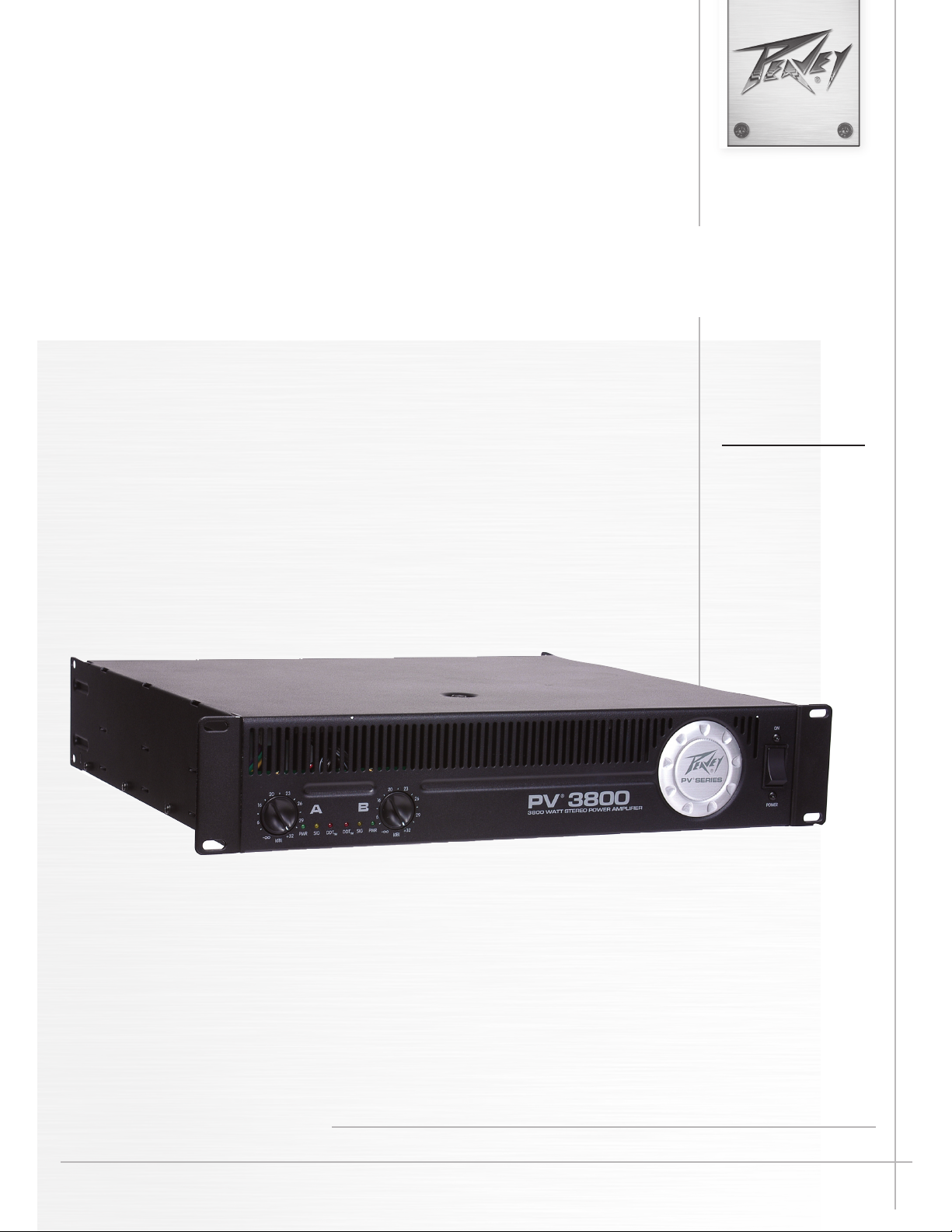
PV
Power Amplifier
3800
Operating
Manual
www.peavey.com
Page 2
Intended to alert the user to the presence of uninsulated “dangerous voltage” within the product’s
enclosure that may be of sufficient magnitude to constitute a risk of electric shock to persons.
Intended to alert the user of the presence of important operating and maintenance (servicing)
instructions in the literature accompanying the product.
CAUTION: Risk of electrical shock — DO NOT OPEN!
CAUTION: To reduce the risk of electric shock, do not remove cover. No user serviceable parts inside.
Refer servicing to qualified service personnel.
WARNING: To prevent electrical shock or fire hazard, this apparatus should not be exposed to rain or
moisture‚ and objects filled with liquids‚ such as vases‚ should not be placed on this apparatus. Before
using this apparatus‚ read the operating guide for further warnings.
Este símbolo tiene el propósito, de alertar al usuario de la presencia de “(voltaje) peligroso” sin
aislamiento dentro de la caja del producto y que puede tener una magnitud suficiente como para
constituir riesgo de descarga eléctrica.
Este símbolo tiene el propósito de alertar al usario de la presencia de instruccones importantes sobre la
operación y mantenimiento en la información que viene con el producto.
PRECAUCION: Riesgo de descarga eléctrica ¡NO ABRIR!
PRECAUCION: Para disminuír el riesgo de descarga eléctrica, no abra la cubierta. No hay piezas útiles
dentro. Deje todo mantenimiento en manos del personal técnico cualificado.
ADVERTENCIA: Para prevenir choque electrico o riesgo de incendios, este aparato no se debe exponer a
la lluvia o a la humedad. Los objetos llenos de liquidos, como los floreros, no se deben colocar encima
de este aparato. Antes de usar este aparato, lea la guia de funcionamiento para otras advertencias.
Ce symbole est utilisé dans ce manuel pour indiquer à l’utilisateur la présence d’une tension dangereuse
pouvant être d’amplitude suffisante pour constituer un risque de choc électrique.
Ce symbole est utilisé dans ce manuel pour indiquer à l’utilisateur qu’il ou qu’elle trouvera d’importantes
instructions concernant l’utilisation et l’entretien de l’appareil dans le paragraphe signalé.
ATTENTION: Risques de choc électrique — NE PAS OUVRIR!
ATTENTION: Afin de réduire le risque de choc électrique, ne pas enlever le couvercle. Il ne se trouve
à l’intérieur aucune pièce pouvant être reparée par l’utilisateur. Confiez I’entretien et la réparation de
l’appareil à un réparateur Peavey agréé.
AVIS: Dans le but de reduire les risques d’incendie ou de decharge electrique, cet appareil ne doit
pas etre expose a la pluie ou a l’humidite et aucun objet rempli de liquide, tel qu’un vase, ne doit
etre pose sur celui-ci. Avant d’utiliser de cet appareil, lisez attentivement le guide fonctionnant pour
avertissements supplémentaires.
Dieses Symbol soll den Anwender vor unisolierten gefährlichen Spannungen innerhalb des Gehäuses
warnen, die von Ausreichender Stärke sind, um einen elektrischen Schlag verursachen zu können.
Dieses Symbol soll den Benutzer auf wichtige Instruktionen in der Bedienungsanleitung aufmerksam
machen, die Handhabung und Wartung des Produkts betreffen.
VORSICHT: Risiko — Elektrischer Schlag! Nicht öffnen!
VORSICHT: Um das Risiko eines elektrischen Schlages zu vermeiden, nicht die Abdeckung enfernen.
Es befinden sich keine Teile darin, die vom Anwender repariert werden könnten. Reparaturen nur von
qualifiziertem Fachpersonal durchführen lassen.
WARNUNG: Um elektrischen Schlag oder Brandgefahr zu verhindern, sollte dieser Apparat nicht
Regen oder Feuchtigkeit ausgesetzt werden und Gegenstände mit Flüssigkeiten gefuellt, wie Vasen,
nicht auf diesen Apparat gesetzt werden. Bevor dieser Apparat verwendet wird, lesen Sie bitte den
Funktionsführer für weitere Warnungen.
2
Page 3
IMPORTANT SAFETY INSTRUCTIONS
WARNING: When using electrical products, basic cautions should always be followed, including the following:
1. Read these instructions.
2. Keep these instructions.
3. Heed all warnings.
4. Follow all instructions.
5. Do not use this apparatus near water.
6. Clean only with a dry cloth.
7. Do not block any of the ventilation openings. Install in accordance with manufacturer’s instructions.
8. Do not install near any heat sources such as radiators, heat registers, stoves or other apparatus (including amplifiers)
that produce heat.
9. Do not defeat the safety purpose of the polarized or grounding-type plug. A polarized plug has two blades with one
wider than the other. A grounding type plug has two blades and a third grounding plug. The wide blade or third prong is
provided for your safety. If the provided plug does not fit into your outlet, consult an electrician for replacement of the
obsolete outlet.
10. Protect the power cord from being walked on or pinched, particularly at plugs, convenience receptacles, and the point
they exit from the apparatus.
11. Only use attachments/accessories provided by the manufacturer.
12. Use only with a cart, stand, tripod, bracket, or table specified by the manufacturer, or sold with the apparatus. When a
cart is used, use caution when moving the cart/apparatus combination to avoid injury from tip-over.
13. Unplug this apparatus during lightning storms or when unused for long periods of time.
14. Refer all servicing to qualified service personnel. Servicing is required when the apparatus has been damaged in
any way, such as when power-supply cord or plug is damaged, liquid has been spilled or objects have fallen into the
apparatus, the apparatus has been exposed to rain or moisture, does not operate normally, or has been dropped.
15. Never break off the ground pin. Write for our free booklet “Shock Hazard and Grounding.” Connect only to a power
supply of the type marked on the unit adjacent to the power supply cord.
16. If this product is to be mounted in an equipment rack, rear support should be provided.
17. Note for UK only: If the colors of the wires in the mains lead of this unit do not correspond with the terminals in your
plug‚ proceed as follows:
a) The wire that is colored green and yellow must be connected to the terminal that is marked by the letter E‚ the earth
symbol‚ colored green or colored green and yellow.
b) The wire that is colored blue must be connected to the terminal that is marked with the letter N or the color black.
c) The wire that is colored brown must be connected to the terminal that is marked with the letter L or the color red.
18. This electrical apparatus should not be exposed to dripping or splashing and care should be taken not to place objects
containing liquids, such as vases, upon the apparatus.
19. Exposure to extremely high noise levels may cause a permanent hearing loss. Individuals vary considerably in susceptibility to noise-induced hearing loss, but nearly everyone will lose some hearing if exposed to sufficiently intense noise
for a sufficient time. The U.S. Government’s Occupational Safety and Health Administration (OSHA) has specified the
following permissible noise level exposures:
Duration Per Day In Hours Sound Level dBA, Slow Response
8 90
6 92
4 95
3 97
2 100
1 1⁄2 102
1 105
1⁄2 110
1⁄4 or less 115
According to OSHA, any exposure in excess of the above permissible limits could result in some hearing loss. Earplugs or protectors to
the ear canals or over the ears must be worn when operating this amplification system in order to prevent a permanent hearing loss, if
exposure is in excess of the limits as set forth above. To ensure against potentially dangerous exposure to high sound pressure levels, it is
recommended that all persons exposed to equipment capable of producing high sound pressure levels such as this amplification system be
protected by hearing protectors while this unit is in operation.
SAVE THESE INSTRUCTIONS!
3
Page 4
WICHTIGE SICHERHEITSHINWEISE
ACHTUNG: Beim Einsatz von Elektrogeräten müssen u.a. grundlegende Vorsichtsmaßnahmen befolgt werden:
1. Lesen Sie sich diese Anweisungen durch.
2. Bewahren Sie diese Anweisungen auf.
3. Beachten Sie alle Warnungen.
4. Befolgen Sie alle Anweisungen.
5. Setzen Sie dieses Gerät nicht in der Nähe von Wasser ein.
6. Reinigen Sie es nur mit einem trockenen Tuch.
7. Blockieren Sie keine der Lüftungsöffnungen. Führen Sie die Installation gemäß den Anweisungen des Herstellers durch.
8. Installieren Sie das Gerät nicht neben Wärmequellen wie Heizungen, Heizgeräten, Öfen oder anderen Geräten (auch Verstärkern),
die Wärme erzeugen.
9. Beeinträchtigen Sie nicht die Sicherheitswirkung des gepolten Steckers bzw. des Erdungssteckers. Ein gepolter Stecker weist
zwei Stifte auf, von denen einer breiter ist als der andere. Ein Erdungsstecker weist zwei Stifte und einen dritten Erdungsstift auf.
Der breite Stift bzw. der dritte Stift dient Ihrer Sicherheit. Sollte der beiliegende Stecker nicht in Ihre Steckdose passen, wenden
Sie sich bitte an einen Elektriker, um die ungeeignete Steckdose austauschen zu lassen.
10. Schützen Sie das Netzkabel, sodass niemand darauf tritt oder es geknickt wird, insbesondere an Steckern oder Buchsen und
ihren Austrittsstellen aus dem Gerät.
11. Verwenden Sie nur die vom Hersteller erhältlichen Zubehörgeräte oder Zubehörteile.
12. Verwenden Sie nur einen Wagen, Stativ, Dreifuß, Träger oder Tisch, der den Angaben des Herstellers entspricht oder zusammen
mit dem Gerät verkauft wurde. Wird ein Wagen verwendet, bewegen Sie den Wagen mit dem darauf befindlichen Gerät besonders
vorsichtig, damit er nicht umkippt und möglicherweise jemand verletzt wird.
13. Trennen Sie das Gerät während eines Gewitters oder während längerer Zeiträume, in denen es nicht benutzt wird, von der
Stromversorgung.
14. Lassen Sie sämtliche Wartungsarbeiten von qualifizierten Kundendiensttechnikern durchführen. Eine Wartung ist erforderlich,
wenn das Gerät in irgendeiner Art beschädigt wurde, etwa wenn das Netzkabel oder der Netzstecker beschädigt wurden,
Flüssigkeit oder Gegenstände in das Gerät gelangt sind, das Gerät Regen oder Feuchtigkeit ausgesetzt wurde, nicht normal
arbeitet oder heruntergefallen ist.
15. Der Erdungsstift darf nie entfernt werden. Auf Wunsch senden wir Ihnen gerne unsere kostenlose Broschüre „Shock Hazard and
Grounding“ (Gefahr durch elektrischen Schlag und Erdung) zu. Schließen Sie nur an die Stromversorgung der Art an, die am
Gerät neben dem Netzkabel angegeben ist.
16. Wenn dieses Produkt in ein Geräte-Rack eingebaut werden soll, muss eine Versorgung über die Rückseite eingerichtet werden.
17. Hinweis – Nur für Großbritannien: Sollte die Farbe der Drähte in der Netzleitung dieses Geräts nicht mit den Klemmen in Ihrem
Stecker übereinstimmen, gehen Sie folgendermaßen vor:
a) Der grün-gelbe Draht muss an die mit E (Symbol für Erde) markierte bzw. grüne oder grün-gelbe Klemme angeschlossen
werden.
b) Der blaue Draht muss an die mit N markierte bzw. schwarze Klemme angeschlossen werden.
c) Der braune Draht muss an die mit L markierte bzw. rote Klemme angeschlossen werden.
18. Dieses Gerät darf nicht ungeschützt Wassertropfen und Wasserspritzern ausgesetzt werden und es muss darauf geachtet
werden, dass keine mit Flüssigkeiten gefüllte Gegenstände, wie z. B. Blumenvasen, auf dem Gerät abgestellt werden.
19. Belastung durch extrem hohe Lärmpegel kann zu dauerhaftem Gehörverlust führen. Die Anfälligkeit für durch Lärm bedingten
Gehörverlust ist von Mensch zu Mensch verschieden, das Gehör wird jedoch bei jedem in gewissem Maße geschädigt, der über
einen bestimmten Zeitraum ausreichend starkem Lärm ausgesetzt ist. Die US-Arbeitsschutzbehörde (Occupational and Health
Administration, OSHA) hat die folgenden zulässigen Pegel für Lärmbelastung festgelegt:
8 90
6 92
4 95
3 97
2 100
1 1⁄2 102
1 105
Dauer pro Tag in Stunden Geräuschpegel dBA, langsame Reaktion
1
1
⁄2 110
⁄4 oder weniger 115
Laut OSHA kann jede Belastung über den obenstehenden zulässigen Grenzwerten zu einem gewissen Gehörverlust führen. Sollte
die Belastung die obenstehenden Grenzwerte übersteigen, müssen beim Betrieb dieses Verstärkungssystems Ohrenstopfen oder
Schutzvorrichtungen im Gehörgang oder über den Ohren getragen werden, um einen dauerhaften Gehörverlust zu verhindern. Um sich vor
einer möglicherweise gefährlichen Belastung durch hohe Schalldruckpegel zu schützen, wird allen Personen empfohlen, die mit Geräten
arbeiten, die wie dieses Verstärkungssystem hohe Schalldruckpegel erzeugen können, beim Betrieb dieses Geräts einen Gehörschutz zu tragen.
BEWAHREN SIE DIESE SICHERHEITSHINWEISE AUF!
4
Page 5
INSTRUCTIONS IMPORTANTES DE SECURITE
ATTENTION: L’utilisation de tout appareil électrique doit être soumise aux precautions d’usage incluant:
1. Lire ces instructions.
2. Gardez ce manuel pour de futures références.
3. Prétez attention aux messages de précautions de ce manuel.
4. Suivez ces instructions.
5. N’utilisez pas cette unité proche de plans d’eau.
6. N’utilisez qu’un tissu sec pour le nettoyage de votre unité.
7. N’obstruez pas les systèmes de refroidissement de votre unité et installez votre unité en fonction des instructions
de ce manuel.
8. Ne positionnez pas votre unité à proximité de toute source de chaleur.
9. Connectez toujours votre unité sur une alimentation munie de prise de terre utilisant le cordon d’alimentation
fourni.
10. Protégez les connecteurs de votre unité et positionnez les cablages pour éviter toutes déconnexions accidentelles.
11. N’utilisez que des fixations approuvées par le fabriquant.
12. Lors de l’utilsation sur pied ou pole de support, assurez dans le cas de déplacement de l’ensemble enceinte/
support de prévenir tout basculement intempestif de celui-ci.
13. Il est conseillé de déconnecter du secteur votre unité en cas d’orage ou de durée prolongée sans utilisation.
14. Seul un technicien agréé par le fabriquant est à même de réparer/contrôler votre unité. Celle-ci doit être contrôlée si
elle a subit des dommages de manipulation, d’utilisation ou de stockage (humidité,…).
15. Ne déconnectez jamais la prise de terre de votre unité.
16. Si votre unité est destinée a etre montée en rack, des supports arriere doivent etre utilises.
17. Note pour les Royaumes-Unis: Si les couleurs de connecteurs du cable d’alimentation ne correspond pas au guide
de la prise secteur, procédez comme suit:
a) Le connecteur vert et jaune doit être connectrer au terminal noté E, indiquant la prise de terre ou correspondant
aux couleurs verte ou verte et jaune du guide.
b) Le connecteur Bleu doit être connectrer au terminal noté N, correspondnat à la couleur noire du guide.
c) Le connecteur marron doit être connectrer au terminal noté L, correspondant à la couleur rouge du guide.
18. Cet équipement électrique ne doit en aucun cas être en contact avec un quelconque liquide et aucun objet
contenant un liquide, vase ou autre ne devrait être posé sur celui-ci.
19. Une exposition à de hauts niveaux sonores peut conduire à des dommages de l’écoute irréversibles. La susceptibilité au bruit varie considérablement d’un individu à l’autre, mais une large majorité de la population expériencera
une perte de l’écoute après une exposition à une forte puissance sonore pour une durée prolongée. L’organisme de
la santé américaine (OSHA) a produit le guide ci-dessous en rapport à la perte occasionnée:
Durée par Jour (heures) Niveau sonore moyen (dBA)
8 90
6 92
4 95
3 97
2 100
1 1⁄2 102
1 105
D’après les études menées par le OSHA, toute exposition au delà des limites décrites ce-dessus entrainera des pertes de l’écoute chez la
plupart des sujets. Le port de système de protection (casque, oreilette de filtrage,…) doit être observé lors de l’opération cette unité ou des
dommages irréversibles peuvent être occasionnés. Le port de ces systèmes doit être observé par toutes personnes susceptibles d’être exposées à des conditions au delà des limites décrites ci-dessus.
1
⁄2 110
1
⁄4 ou inférieur 115
GARDEZ CES INSTRUCTIONS!
5
Page 6
INSTRUCCIONES IMPORTANTES PARA SU SEGURIDAD
CUIDADO: Cuando use productos electrónicos, debe tomar precauciones básicas, incluyendo las siguientes:
1. Lea estas instrucciones.
2. Guarde estas instrucciones.
3. Haga caso de todos los consejos.
4. Siga todas las instrucciones.
5. No usar este aparato cerca del agua.
6. Limpiar solamente con una tela seca.
7. No bloquear ninguna de las salidas de ventilación. Instalar de acuerdo a las instrucciones del fabricante.
8. No instalar cerca de ninguna fuente de calor como radiadores, estufas, hornos u otros aparatos (incluyendo amplificadores)
que produzcan calor.
9. No retire la patilla protectora del enchufe polarizado o de tipo “a Tierra”. Un enchufe polarizado tiene dos puntas, una de
ellas más ancha que la otra. Un enchufe de tipo “a Tierra” tiene dos puntas y una tercera “a Tierra”. La punta ancha (la
tercera ) se proporciona para su seguridad. Si el enchufe proporcionado no encaja en su enchufe de red, consulte a un
electricista para que reemplaze su enchufe obsoleto.
10. Proteja el cable de alimentación para que no sea pisado o pinchado, particularmente en los enchufes, huecos, y los puntos
que salen del aparato.
11. Usar solamente añadidos/accesorios proporcionados por el fabricante.
12. Usar solamente un carro, pie, trípode, o soporte especificado por el fabricante, o vendido junto al aparato. Cuando se use
un carro, tenga cuidado al mover el conjunto carro/aparato para evitar que se dañe en un vuelco. No suspenda esta caja de
ninguna manera.
13. Desenchufe este aparato durante tormentas o cuando no sea usado durante largos periodos de tiempo.
14. Para cualquier reparación, acuda a personal de servicio cualificado. Se requieren reparaciones cuando el aparato ha sido
dañado de alguna manera, como cuando el cable de alimentación o el enchufe se han dañado, algún líquido ha sido
derramado o algún objeto ha caído dentro del aparato, el aparato ha sido expuesto a la lluvia o la humedad, no funciona de
manera normal, o ha sufrido una caída.
15. Nunca retire la patilla de Tierra.Escríbanos para obtener nuestro folleto gratuito “Shock Hazard and Grounding” (“Peligro
de Electrocución y Toma a Tierra”). Conecte el aparato sólo a una fuente de alimentación del tipo marcado al lado del cable
de alimentación.
16. Si este producto va a ser enracado con más equipo, use algún tipo de apoyo trasero.
17. Nota para el Reino Unido solamente: Si los colores de los cables en el enchufe principal de esta unidad no corresponden
con los terminales en su enchufe‚ proceda de la siguiente manera:
a) El cable de color verde y azul debe ser conectado al terminal que está marcado con la letra E‚ el símbolo de Tierra
(earth)‚ coloreado en verde o en verde y amarillo.
b) El cable coloreado en azul debe ser conectado al terminal que está marcado con la letra N o el color negro.
c) El cable coloreado en marrón debe ser conectado al terminal que está marcado con la letra L o el color rojo.
18. Este aparato eléctrico no debe ser sometido a ningún tipo de goteo o salpicadura y se debe tener cuidado para no poner
objetos que contengan líquidos, como vasos, sobre el aparato.
19. La exposición a altos niveles de ruido puede causar una pérdida permanente en la audición. La susceptibilidad a la pérdida
8 90
6 92
4 95
3 97
2 100
1 1⁄2 102
1 105
de audición provocada por el ruido varía según la persona, pero casi todo el mundo perderá algo de audición si se expone
a un nivel de ruido suficientemante intenso durante un tiempo determinado. El Departamento para la Salud y para la
Seguridad del Gobierno de los Estados Unidos (OSHA) ha especificado las siguientes exposiciones al ruido permisibles:
Duración por Día en Horas Nivel de Sonido dBA, Respuesta Lenta
1
⁄2 110
1
⁄4 o menos 115
De acuerdo al OSHA, cualquier exposición que exceda los límites arriba indicados puede producir algún tipo de pérdida en la audición.
Protectores para los canales auditivos o tapones para los oídos deben ser usados cuando se opere con este sistema de sonido para prevenir una pérdida permanente en la audición, si la exposición excede los límites indicados más arriba. Para protegerse de una exposición a
altos niveles de sonido potencialmente peligrosa, se recomienda que todas las personas expuestas a equipamiento capaz de producir altos
niveles de presión sonora, tales como este sistema de amplificación, se encuentren protegidas por protectores auditivos mientras esta unidad esté operando.
GUARDE ESTAS INSTRUCCIONES!
6
Page 7

ENGLISH
PV® 3800
Power Amplifier
Congratulations on your purchase of the PV 3800, a power amplifier designed for years of reliable, flawless operation under
rigorous use. This amplifier offers the sonic superiority and unsurpassed reliability for which Peavey is famous, while remaining surprisingly compact. Advanced technology and extensive protection circuitry allow operation with greater efficiency into
difficult loads and power conditions. The DDT™ (Distortion Detection Technique) circuitry ensures trouble-free operation into
loads as low as 2 ohms. DDT protects drivers and ensures that sonic integrity is maintained, even in extreme overload conditions. The PV 3800’s high-efficiency design uses tunnel-cooled heat sinks and variable-speed DC fans. This cooling topology
maintains a lower overall operating temperature, resulting in longer output transistor life. For your safety, read the important
precautions section, as well as input, output and power connection instructions.
Although the PV 3800 amplifier is simple to operate and housed in an ultra-strong steel chassis, improper use can be dan-
gerous. This amplifier is very highpowered and can put out high voltages and sizable currents at frequencies up to 30 kHz.
Always use safe operating techniques when operating this amplifier.
Before you send signal through your amplifier, it is very important to ensure that the product has the proper AC line
voltage supplied. You can find the proper voltage for your amp printed next to the IEC line (power) cord on the rear
panel of the unit. Each product feature is numbered. Refer to the front panel diagram in this manual to locate the
particular features next to its number.
Please read this guide carefully to ensure your personal safety as well as the safety of your amplifier.
FEATURES:
• Distortion Detection Technique (DDT)
• LFC™ Inpedance Sensing
• RAMPUP™ Signal Control
• 100 Hz Crossover
• Three front panel LEDs: DDT, Signal and Power
• Three operation choices: Stereo, Parallel and Bridged
7
Page 8

SAVE THESE INSTRUCTIONS
Save the carton and packing materials!
1
Should you ever need to ship the
unit, use only the original factory
packing.
For replacement packaging, call Peavey
Customer Service Department directly.
Read all documentation before oper-
2
ating your equipment. Retain all documentation for future reference.
Follow all instructions printed on
3
unit chassis for proper operation.
Never hold a power switch or cir-
4
cuit breaker in the "ON" position if
it won’t stay there by itself!
Do not use the unit if the electrical
5
power cord is frayed or broken.
The power supply cords should be
routed so that they are not likely to
be walked on or pinched by items
placed upon or against them.
Always operate the unit with the AC
6
ground wire connected to the electrical system ground. Precautions
should be taken so that the means
of grounding of a piece of equipment
is not defeated.
Damage caused by connection to
7
improper AC voltage is not covered
by any warranty. Mains voltage must
be correct and the same as that printed on the rear of the unit.
Do not ground any hot (red) terminal.
8
Never connect a hot (red) output to
ground or to another hot (red) output!
Power down and disconnect units
9
from mains voltage before making
connections.
Do not drive the inputs with a sig-
10
nal level greater than that required
to enable equipment to reach full
output.
Do not run the output of any amplifier
11
channel back into another channel’s
input.
Do not parallel- or series-connect
an amplifier output with any other
amplifier output.
Peavey is not responsible for dam-
age to loudspeakers for any reason.
Do not connect the inputs or out-
12
puts of amplifiers to any other
voltage source such as a battery,
mains source, or power supply,
regardless of whether the amplifier is turned on or off.
Connecting amplifier outputs to oscil-
13
loscopes or other test equipment
while the amplifier is in bridged mono
mode may damage both the amplifier
and test equipment!
Do not spill water or other liquids
14
into or on the unit, or operate the
unit while standing in liquid.
Do not block fan intake or exhaust
15
ports.
Do not operate equipment on a
surface or in an environment which
may impede the normal flow of air
around the unit, such as a bed,
rug, weathersheet, carpet or completely enclosed rack.
If the unit is used in an extremely
16
dusty or smoky environment the
unit should be periodically blown
free of foreign matter.
Do not use the unit near stoves,
17
heat registers, radiators or other
heat-producing devices.
The equipment power cord should be
18
unplugged from the outlet when left
unused for a long period of time.
Service Information
Do not remove the cover!
Removing the cover will expose you
to potentially dangerous voltages.
There are no user-serviceable parts
inside.
Equipment should be serviced by
qualified service personnel when:
A. The power supply cord or the plug
has been damaged.
B. The equipment has been exposed to
rain.
C. The equipment does not appear to
operate normally or exhibits a marked
change in performance.
D. The equipment has been dropped or
the enclosure damaged.
To obtain service:
contact your nearest Peavey
Service Center, Distributor, Dealer
or contact Peavey at 601.483.5365
USA or visit www.peavey.com for
additional information, email techserve@peavey.com
8
Page 9

Installation
Unpacking
Upon unpacking, inspect the
amplifier. If you find any damage,
notify your supplier immediately.
Only the consignee may institute a
claim with the carrier for damage
incurred during shipping. Be sure
to save the carton and all packing
materials. Should you ever need to
ship the unit back to Peavey, one
of its offices, service centers or the
supplier, use only the original factory packing. If the shipping carton
is unavailable, contact Peavey to
obtain a replacement.
Because of the complexity of the design and the risk of electrical shock,
all repairs must be completed only
by qualified technical personnel.
Mounting
The PV® 3800 amplifier will
mount in standard 19" racks. Rear
mounting ears are also provided
for additional support, which is
recommended in non-permanent
installations like mobile or touring
sound systems.
Connecting Power
The PV 3800 amplifier power requirements are rated at 1/8 power
(typical music conditions) and 1/3
power (extreme music conditions). The
maximum power current draw rating is
limited only by the front panel circuit
breaker. Consult the specifications in
the Specification section for figures on
the current that each amplifier will demand. Make sure the mains voltage is
correct and is the same as that printed
on the rear of the amplifier. Damage
caused by connecting the amplifier to
improper AC voltage is not covered by
any warranty. Unless otherwise specified when ordered, Peavey amplifiers
shipped to customers are configured
as follows:
Option 1 North America
120VAC / 60 Hz
Option 2 Europe, Asia
230/240VAC / 50 Hz
Option 3 Australia
240VAC / 50 Hz
Option 4 South America
120VAC / 60 Hz or 240VAC / 50 Hz
Always turn off and disconnect the amplifier
from mains voltage before making audio
connections. Also, as an extra precaution, turn the
attenuators down during power-up.
Cooling Requirements
The PV 3800 amplifier uses a
forced-air cooling system to maintain a low, consistent operating
temperature. Air is drawn into the
amplifier by fan(s) on the rear panel,
courses through the cooling fins of
the tunnel-configured channel heat
sink(s), and then exhausts through
the front panel grille. If either heat
sink gets too hot, its sensing circuit
will open the output relay, disconnecting the load from that particular
channel. The PV 3800 utilizes one
common heat sink and a single fan,
but retains the separate circuitry.
NOTE: Maintain an adequate air
supply at the back of the amplifier
and enough space around the front
of the amplifier to allow the cooling
air to escape. If the amp is rack
mounted, do not use doors or
covers on the front of the rack;
the exhaust air must flow without
resistance. If you are using racks
with closed backs, use fans on the
rear rack panel to pressurize the
rack and ensure an ample air supply.
a
a
Operating Precautions
Make sure the mains voltage is correct and the same as that printed on the rear of the amplifier. Damage caused by connecting the amplifier to improper AC voltage is not covered by any warranty. See the Connecting Power section for more information on voltage requirements.
Although the PV 3800 amplifier has RAMPUP™ circuitry, which raises the signal level gradually after the output relay closes,
remember to have the gain controls turned down during power-up to prevent speaker damage if there is a high signal level at
the inputs. Whether you buy or make them, use good-quality connections, input cables and speaker cables, along with good
soldering technique, to ensure trouble-free operation. Most intermittent problems are caused by faulty cables.
Consult the Wire Gauge Chart to determine proper gauges for different load impedances and cable lengths. Remember that
cable resistance robs amplifier power in two ways: power lost directly to resistance (I2R loss), and by increasing the total load
impedance, thereby decreasing the power demanded of the amplifier. Also, make sure the mode switch is correctly set for the
desired application. See Sections on Stereo, Parallel and Bridged Mono Mode for more information.
Make certain that there is enough space around the front and rear of the amplifier to allow the heated air
to escape.
Suggestion: In racks with closed backs, allow at least one standard-rack-space opening for every four
a
mounted power amplifiers.
9
Page 10

Front Panel
2
3
4
5
1
AC POWER SWITCH/CIRCUIT BREAKER
The PV® 3800 amplifier has a combination AC switch/circuit breaker on the front panel. If the switch shuts
off during normal use, push it back to the ON position once. If it will not stay on, the amplifier needs
servicing.
INDICATORS
The PV 3800 amplifier features three front panel LED indicators per channel: DDT™, SIGNAL and POWER.
These LED indicators inform the user of each channel’s operating status and warn of possible abnormal
conditions.
1
2
DDT (DISTORTION DETECTION TECHNIQUE) LED
A channel’s DDT LED will light at the onset of clipping. If the LEDs are flashing quickly and intermittently, the channel is just at the clip threshold. A steady, bright glow means the amp is clip limiting,
or reducing gain to prevent severely clipped waveforms from reaching the loudspeakers. See the
Distortion Detection Technique section for more information. During initial power-up the DDT LED
will light to indicate that the RAMPUP™ gain reduction circuitry is activated. This prevents sudden
signal bursts when the speaker relays are closed.
3
SIGNAL LED
This LED lights when its channel produces an output signal of about 4 volts RMS or more (0.1 volt or more
at the input, with 0 dB attenuation and standard x40 voltage gain). This signal indicates whether a signal
is reaching and being amplified by the amplifier.
4
POWER LED
The Power LED indicates that its channel’s output relay is closed and the
channel is operational. It lights under normal operation and remains on, even
when the channel is in Distortion Detection Technique or DDT gain reduction.
These protection features leave the output relay closed. If the Power LED
The power only breaks
one side of the AC mains.
Hazardous energy may be
present in the enclosure
when the power switch is in
the OFF position.
goes off, there is no signal at the output connectors.
5
INPUT ATTENUATORS
Whenever possible, set the attenuators fully clockwise to maintain optimum
system headroom. The input attenuator controls, located at the front panel
(one for channel A, one for channel B), adjust gain for their respective amplifier channels in all modes. See the specifications at the end of this manual for
standard voltage gain and input sensitivity information.
When operating in the Bridged
Mode, both attenuators must
be in the same position so the
speaker load will be equally
shared between the channels.
See the section on Bridged
Mono operation for more
information and precautions.
a
a
10
Page 11

Rear Panel
6
6
AC POWER INLET:
7
9
10
8
11
This is the receptacle for an IEC line cord, which provides AC power to the unit. Connect the line cord to
this connector to provide power to the unit. Damage to the equipment may result if improper line voltage is used. (See line voltage marking on unit).
Never break off the ground pin on any equipment. It is provided for your safety. If the outlet used
does not have a ground pin, a suitable grounding adapter should be used and the third wire should be
grounded properly. To prevent the risk of shock or re hazard, always make sure that the amplier and
all associated equipment is properly grounded.
NOTE: FOR U.K. ONLY
As the colors of the wires in the mains lead of this apparatus may not correspond with the colored markings identifying the terminals in your plug, proceed as follows: (1) The wire which is colored green and
yellow must be connected to the terminal which is marked by the letter E, or by the Earth symbol, or
colored green or green and yellow. (2) The wire which is colored blue must be connected to the terminal
which is marked with the letter N, or the color black. (3) The wire which is colored brown must be connected to the terminal which is marked with the letter L, or the color red.
To avoid the risk of electrical shock, do not place ngers or any other objects into empty tube sockets
while power is being supplied to unit.
7
LOW CUT SWITCH
This switch is used to activate the LOW CUT filter for the corresponding channel. It is a push-type switch,
that requires a small tool to activate. The IN position routes the input signals through the 40 Hz LOW CUT
filter, while the OUT position bypasses the filter. This filter will cut extremely low frequencies, protecting
speakers from the possibility of over-excursion. The filter low-frequency rolloff is 12 dB per octave. The
LOW CUT filter for each channel will function independently of the crossover function.
CROSSOVER SWITCH (100 Hz crossover)
8
This switch is used to activate the 100 Hz crossover for the corresponding channel. It is also a
push-type switch and requires a small tool to activate. The PV 3800 offers two 100 Hz crossovers.
These are specially designed features that enhance the response of most loudspeakers in a typical
bi-amped application. Rather than having a flat output curve, these crossovers use special filters
to tailor the response and provide a flat acoustical output. This type of crossover sounds more
natural than conventional state-variable crossovers. With the switch IN, the input signals are routed
through the crossover and the low frequencies are automatically sent to the corresponding channel. At the same time, the high frequencies are sent to the HIGH OUT (9) jack and must then be
patched to the INPUT of the other channel of this amplifier or to another amplifier input to complete the bi-amped system. With the switch OUT, the crossover is defeated and the input signal is
11
Page 12

Rear Panel
12
6
13
7
9
10
8
11
routed directly to the respective power amp channel. The crossover frequency is fixed at 100 Hz and
cannot be changed. The crossover configuration is a four-pole Linkwitz-Riley approximation.
HIGH OUT JACKS
9
This 1/4” jack supplies high-frequency output signals from the activated crossover for patching to
this amplifier and/or additional power amplifier inputs. Unlike the low-frequency crossover output
that is automatically routed to the associated channel, the high-frequency output signal must be
patched to some suitable input in order to complete the bi-amped system. This 1/4” jack also provides an unbalanced (tip/sleeve) output to be patched with single-conductor shielded cables.
10
CONN. MODE SELECT SWITCH
Depressing the rear panel CONN. MODE select switch connects both input connectors together in
parallel. This directs the same input signal to both channels and allows one connector to be used
with a patch cable to drive another amplifier. In the OUT position, both input connectors operate
independently. Do not operate the CONN. MODE select switch with the amplifier powered on. See
the sections on Stereo, Parallel and Bridged Mono Mode for more information.
SELECT SWITCH
11
The rear panel AMP MODE select switch determines if the amplifier is in stereo (two channels) or in
Bridged Mono Mode. Do not operate the AMP MODE select switch with the amplifier powered on. See
the Operations Mode section for more information on Stereo, Parallel and Bridged Mono Mode applications.
CONNECTING INPUTS
12
Input connections are made via the 3-pin XLR (pin 2+) or 6.3 mm plug “Combi” connectors on the rear
panel of the amplifier. The inputs are actively balanced. The input overload point is high enough to accept
the maximum output level of virtually any signal source.
CONNECTING OUTPUTS
13
All models have two output (speaker) connections per channel. Cables can be connected with banana
plugs, spade lugs, or bare wire to the five-way binding posts. The preferred method is connection via the
Speakon® connectors.
12
Page 13

Operation Modes
Stereo Operation
For stereo (dual channel) operation, turn the amplifier off and set the mode select switches on the back panel to
the OUT (extended) position. In this mode, both channels operate independently of each other with their input
attenuators controlling their respective levels. For example, a signal at channel A’s input produces an amplified
signal at channel A’s output, while a signal at channel B’s input produces an amplified signal at channel B’s output.
Parallel Operation
For parallel (dual channel/single input) operation, turn the amplifier off and set the connector mode (Conn,
Mode) switch to the parallel position by depressing the switch. Both input connectors are then strapped together
and drive both channels with the same input signal. Because both connectors are strapped together, either connector can be used with a patch cable to drive the input of another amplifier. Output connections are the same as
in the Stereo Mode. In Parallel Mode, both input attenuators remain active, allowing users to set different levels
for each channel. Power and other general performance specifications are the same as in the Stereo Mode.
Bridged Operation
Both amplifier channels can be bridged together to make a very powerful single-channel monaural amplifier. Use
extreme caution when operating in bridged mode; potentially lethal voltage may be present at the output terminals. To bridge the amplifier, depress the rear panel Amp Mode switch (11) to the IN position. Direct the signal
to channel A’s input and connect the speakers across pin +1 and pin +2 of the channel A Speakon® output connector. Only channel A’s input attenuator is active while in Bridged Mono mode. Both connectors are strapped
together, so either connector can be used with a patch cable to drive the input of another amplifier. When oper-
ating in the Bridged Mode, both attenuators must be in the same position so the speaker load will be
equally shared between the channels.
Unlike the Stereo and Parallel Modes, in which one side of each output is at ground, in
the Bridged Mode both sides are hot. Pin +1 is Channel A’s side, which is the same polarity as the input. The minimum nominal load impedance in the Bridge Mode is 4 ohms,
which is equivalent to driving both channels at 2 ohms. Driving bridged loads of less than
4 ohms will activate DDT™ circuitry, resulting in a loss of power and potential thermal
overload.
13
Page 14

Protection Features
The PV® 3800 amplifier incorporates several circuits to protect both themselves and loudspeakers under virtually any situation. Peavey has attempted to make the amplifiers as foolproof as possible by making them immune
to short and open circuits, mismatched loads, DC voltage, and overheating. If a channel goes into the Distortion
Detection Technique or DDT™ gain reduction mode, the speaker load remains connected, but clipping percentage or output power are instantly reduced. DC voltage on the output, excessive subsonic frequencies or thermal
overload will cause the channel’s output relay to disconnect the speaker load until the problem is corrected or
the amplifier cools down.
Distortion Detection Technique™ (DDT)
Any time a channel is driven into hard, continuous clipping, the DDT circuit will automatically reduce the channel
gain to a level just slightly into clipping, guarding the speakers against the damaging high power continuous
square waves that may be produced. Situations that may activate the DDT circuit include uncontrolled feedback,
oscillation, an improper equipment setting or malfunction upstream from the amplifier. Normal program
transients will not trigger the DDT, only steady, excessive clipping will. The DDT LED will glow brightly and
continuously when limiting occurs.
LFC™ Impedance Sensing
The PV 3800 amplifier features innovative circuitry that allows safe operation into any load. When an amplifier
sees a load that overstresses the output stage, the Load Fault Correction (LFC) circuit adjusts the channel gain to
a safe level. This method of output-stage protection is far superior to conventional, brute force-type limiting found
on other amplifiers. The LFC circuit is sonically transparent in normal use and unobtrusive when activated.
Thermal Protection
Internal fans keep the amplifier operating well within its intended temperature range under all normal conditions.
If a channel’s heat sink temperature reaches 75°C, which may indicate an obstructed air supply, that channel will
independently protect itself by disconnecting its load and shutting down until it has cooled. During this time, the
POWER LED will go out, the DDT LEDs will remain lit and the cooling fans will continue running at high speed.
Short Circuit
If an output is shorted, the LFC and thermal circuits will automatically protect the amplifier. The LFC circuit senses
the short circuit as an extremely stressful load condition and attenuates the signal, protecting the channel’s
output transistors from over-current stress. If the short circuit remains, the channel will eventually thermally
protect itself by disconnecting the load.
DC Voltage Protection
If an amplifier channel detects DC voltage or subsonic frequencies at its output terminals, its output relay will
immediately open to prevent loudspeaker damage.
14
Page 15

Protection Features
Turn-On/Turn-Off Protection
At power-up, the amplifier stays in the protect mode with outputs disconnected for approximately six seconds
while the power supplies charge and stabilize. While the output relays are open, the DDT™ LEDs light. When
power is removed, the speaker loads immediately disconnect so that no thumps or pops are heard.
RAMPUP™ Signal Control
Whenever a PV® 3800 amplifier powers up or comes out of a protect mode, the RAMPUP circuit activates. While
the speakers are disconnected, the RAMPUP circuit fully attenuates the signal and activates the DDT LED. After
the output relay closes, the signal slowly and gradually raises to its set level. The PWR LED will illuminate and
the DDT LED will turn off when the signal is no longer attenuated. The RAMPUP Signal Control circuit has some
important advantages over conventional instant-on circuits:
1. If a signal is present during power-up (or when coming out of protect), the speakers are
spared a sudden, potentially damaging burst of audio power.
2. Because the gain is reduced until after the output relay closes, no arcing occurs at the
contacts. This extends the contacts’ useful life.
15
Page 16

Safety
Speaker Protection
All loudspeakers have electrical, thermal and physical limits that must be observed to prevent damage or failure.
Too much power, low frequencies applied to high frequency drivers, severely clipped waveforms and DC voltage
can all be fatal to cone and compression drivers. The Peavey PV® 3800 amplifier automatically protects speakers
from DC voltages and subsonic signals. For more information, see the section on Protection Features. Mid- and
high-frequency speakers, especially compression drivers, are highly susceptible to damage from overpowering,
clipped waveforms or frequencies below their rated pass band. Be extremely careful that the low and mid bands
of an electronic crossover are connected to the correct amplifiers and drivers and not accidentally connected
to those for a higher frequency band. The amplifier’s clipping point is its maximum peak output power and can
deliver more power than many speakers can safely handle. Be sure the peak power capability of the amplifier is
not excessive for your speaker system.
To ensure that the speakers never receive excessive power and that the amplifier never clips, use a properly
adjusted external limiter (or a compressor with a ratio of 10:1 or higher) to control power output. In systems with
active electronic crossovers, use one for each frequency band. The clip limiter will automatically limit the duration of continuous square waveforms applied to the speakers. The amplifier will, however, allow normal musical
transient bursts to pass. Some speaker systems are packaged with processors that have power limiting circuits
and should not require additional external limiting.
Fuses may also be used to limit power to speaker drivers, although as current-limiting (rather than voltage-limiting) devices they are an imperfect solution. As the weakest links, fuses only limit once before needing replacement. Some poor-quality fuses have a significant series resistance that could degrade the amplifier’s damping of
the speaker’s motion and may even deteriorate the system’s sound quality. If you elect to use fuses, check with
the speaker manufacturer to determine the proper current rating and time lag required.
Do not drive any low-frequency speaker enclosure with frequencies lower than its own tuned frequency. The
reduced acoustical damping could cause a ported speaker to bottom out even at moderate power. Consult the
speaker system specifications to determine its frequency limits.
Amplifier Maintenance and User Responsibility
A PV 3800 amplifier requires no routine maintenance and should never need any internal adjustment during
its lifetime. Your PV 3800 amplifier is very powerful and can be potentially dangerous to loudspeakers and
humans alike. It is your responsibility to read the Important Precautions section in the front of this manual and
to make sure that the amplifier is installed, wired and operated properly. Many loudspeakers can be easily
damaged or destroyed by overpowering, especially with the high power available from a bridged amplifier.
Read the Speaker Protection section and always be aware of the speaker’s continuous and peak power
capabilities.
16
Page 17

PV® 3800 Specications
Rated Power Bridge 8 ohms
Rated Power (2 x 4 ohms)
Rated Power (2 x 8 ohms)
Rated Power (1 x 4 ohms)
Rated Power (1 x 8 ohms)
Minimum Load Impedance
Maximum RMS Voltage
Frequency Response
Power Bandwidth
T.H.D. (2 x 4 ohms)
T.H.D. (2 x 8 ohms)
Input CMRR
Voltage Gain
Crosstalk
Hum and Noise
Slew Rate
Damping Factor (8 ohms)
Phase Response
2650 watts @ 1 kHz at <0.1% T.H.D.
1300 watts per channel @ 1 kHz at <0.05% T.H.D.
both channels driven
775 watts per channel @ 1 kHz at <0.05% T.H.D.
both channels driven
1500 watts @ 1 kHz at <0.05% T.H.D.
875 watts @ 1 kHz at <0.05% T.H.D.
4 ohms
93 volts
10 Hz - 100 kHz; +0, -2 dB at 1 watt
10 Hz - 35 kHz; +0, -3 dB at rated 4 ohm power
<0.1% @ 1050 watts per channel from 20 Hz to
20 kHz
<0.1% @ 700 watts per channel from 20 Hz to
20 kHz
>- 55 dB @ 1 kHz
x40 (32 dB)
> -55 dB @ 1 kHz at rated power @ 8 ohms
> -108 dB, “A” weighted reference to rated power
@ 8 ohms
> 15V/us
> 500:1 @ 20 Hz - 1 kHz
+5 to - 12 degrees from 20 Hz to 20 kHz
Input Sensitivity (x40)
Input Impedance
Current Draw @ 1/8 Power
Current Draw @ 1/3 Power
Cooling
Controls
Indicator LEDs
Protection
Connectors
Construction
Dimensions
Net Weight
Gross Weight
1.88 volts +/- 3% for 1 kHz, 4 ohm rated power,
15 k ohms, balanced
1185 watts @ 4 ohms
720 watts @ 8 ohms
2975 watts @ 4 ohms
1835 watts @ 8 ohms
Two front panel temperature dependent variable
speed 80 mm DC fans
2 front panel attenuators, rear panel Mode switches
2 DDT (Distortion Detection Technique), 2 Signal
presence, 2 Active Status
Thermal, DC, turn-on bursts, subsonic, incorrect
loads
Per channel, Combi XLR & 6.3 mm phone input,
Speakon® and Binding speaker output, 15 amp IEC
mains connector
14 ga. steel with cast front panel and cast handles
88.9 mm x 482.6 mm x 376.3 mm + 31.8 for rear
support ears and connectors
(3.5" x 19" x 14.81" + 1.25") + 38.1 mm (1.5")
handle depth
19.5 kg (43 lbs)
20.6 kg (45.5 lbs)
All power measurements made at 120 VAC, power transformer cold. 2 ohm power is time limited by magnetic circuit breaker.
Features and specifications subject to change without notice.
17
Page 18

cable length (in feet)
feet
5
Wire Gauge Chart
standard
wire gauge power loss into power loss into power loss into
(AWG) 8 Ω load (%) 4 Ω load (%) 2 Ω load (%)
18
16
.79
.50
1.58
1.00
3.16
2.00
10
40
feet
feet
14
12
10
18
16
14
12
10
18
16
14
12
10
.31
.20
.125
1.58
1.00
.62
.40
.25
8.00
4.00
2.50
1.60
1.00
.62
.40
.25
3.16
2.0
1.25
.80
.50
12.60
8.00
5.00
3.20
2.00
1.24
.80
.50
6.32
4.00
2.50
1.60
1.00
25.20
1.60
10.00
6.40
4.00
80
feet
8
16
14
12
10
.625
8.00
5.00
3.20
2.00
18
1.25
16.00
10.00
6.40
4.00
2.50
32.00
20.00
12.80
8.00
Page 19

PEAVEY ELECTRONICS CORPORATION LIMITED WARRANTY
Logo referenced in Directive 2002/96/EC Annex IV
(OJ(L)37/38,13.02.03 and defined in EN 50419: 2005
The bar is the symbol for marking of new waste and
is applied only to equipment manufactured after
13 August 2005
Effective Date: July 1, 1998
What This Warranty Covers
Your Peavey Warranty covers defects in material and workmanship in Peavey products purchased and serviced in the U.S.A. and Canada.
What This Warranty Does Not Cover
The Warranty does not cover: (1) damage caused by accident, misuse, abuse, improper installation or operation, rental, product modification or neglect; (2) damage occurring during shipment; (3) damage caused by repair or service performed by persons not authorized by Peavey; (4) products on which the serial number
has been altered, defaced or removed; (5) products not purchased from an Authorized Peavey Dealer.
Who This Warranty Protects
This Warranty protects only the original retail purchaser of the product.
How Long This Warranty Lasts
The Warranty begins on the date of purchase by the original retail purchaser. The duration of the Warranty is as follows:
Product Category Duration
Guitars/Basses, Amplifiers, Pre-Amplifiers, Mixers, Electronic
Crossovers and Equalizers 2 years (+ 3 years)*
Drums 2 years (+ 1 year)*
Enclosures 3 years (+ 2 years)*
Digital Effect Devices and Keyboard and MIDI Controllers 1 year (+ 1 year)*
Microphones 2 years
Speaker Components (incl. speakers, baskets, drivers,
diaphragm replacement kits and passive crossovers)
and all Accessories 1 year
Tubes and Meters 90 days
[*Denotes additional warranty period applicable if optional Warranty Registration Card is completed and returned to Peavey by original retail purchaser within 90 days
of purchase.]
What Peavey Will Do
We will repair or replace (at Peavey's discretion) products covered by warranty at no charge for labor or materials. If the product or component must be shipped to
Peavey for warranty service, the consumer must pay initial shipping charges. If the repairs are covered by warranty, Peavey will pay the return shipping charges.
How To Get Warranty Service
(1) Take the defective item and your sales receipt or other proof of date of purchase to your Authorized Peavey Dealer or Authorized Peavey Service Center.
OR
(2) Ship the defective item, prepaid, to Peavey Electronics Corporation, International Service Center, 412 Highway 11 & 80 East, Meridian, MS 39301 or Peavey
Canada Ltd., 95 Shields Court, Markham, Ontario, Canada L3R 9T5. Include a detailed description of the problem, together with a copy of your sales receipt or
other proof of date of purchase as evidence of warranty coverage. Also provide a complete return address.
Limitation of Implied Warranties
ANY IMPLIED WARRANTIES, INCLUDING WARRANTIES OF MERCHANTABILITY AND FITNESS FOR A PARTICULAR PURPOSE, ARE LIMITED IN DURATION TO THE
LENGTH OF THIS WARRANTY.
Some states do not allow limitations on how long an implied warranty lasts, so the above limitation may not apply to you.
Exclusions of Damages
PEAVEY'S LIABILITY FOR ANY DEFECTIVE PRODUCT IS LIMITED TO THE REPAIR OR REPLACEMENT OF THE PRODUCT, AT PEAVEY'S OPTION. IF WE ELECT TO
REPLACE THE PRODUCT, THE REPLACEMENT MAY BE A RECONDITIONED UNIT. PEAVEY SHALL NOT BE LIABLE FOR DAMAGES BASED ON INCONVENIENCE, LOSS OF
USE, LOST PROFITS, LOST SAVINGS, DAMAGE TO ANY OTHER EQUIPMENT OR OTHER ITEMS AT THE SITE OF USE, OR ANY OTHER DAMAGES WHETHER INCIDENTAL,
CONSEQUENTIAL OR OTHERWISE, EVEN IF PEAVEY HAS BEEN ADVISED OF THE POSSIBILITY OF SUCH DAMAGES.
Some states do not allow the exclusion or limitation of incidental or consequential damages, so the above limitation or exclusion may not apply to
you.
This Warranty gives you specific legal rights, and you may also have other rights which vary from state to state.
If you have any questions about this warranty or service received or if you need assistance in locating an Authorized Service Center, please contact the Peavey
International Service Center at (601) 483-5365 / Peavey Canada Ltd. at (905) 475-2578.
Features and specifications subject to change without notice.
19
Page 20

Features and specifications subject to change without notice.
Peavey Electronics Corporation • 5022 Hartley Peavey Drive • Meridian, MS 39305
(601) 483-5365 • FAX (601) 486-1278 • www.peavey.com
© 2006 80303154
 Loading...