

Page 1
Page 2
Intended to alert the user to the presence of uninsulated “dangerous voltage” within the product’s enclosure
A
A
CAUTION: Risk of electrical shock - DO NOT OPEN!
CAUTION: To reduce the risk of electric shock, do not remove cover. No user serviceable parts inside. Refer servicing to
qualified service personnel.
WARNING: To prevent electrical shock or fire hazard, do not expose this appliance to rain or moisture. Before using this
appliance, read the operating guide for further warnings.
A
A
PRECAUCION: Riesgo de corrientazo - No
PRECAUCION:
reparar. Deje todo mantenimiento a
that may be of sufficient magnitude to constitute a risk of electric shock to persons.
Intended to alert the user of the presence of important operating and maintenance (servicing) instructions in the
literature accompanying the product.
Este simbolo tiene el proposito de alertar al usuario de la presencia de “(voltaje) peligroso” que no tiene
aislamiento dentro de la caja
corrientazo.
Este simbolo tiene el propdsito de alertar al usario de la presencia de instruccones importantes sobre la operation
y mantenimiento en la literatura que viene con el producto.
Para
disminuir el riesgo de corrientazo, no
de1
product0 que puede tener una magnitud suficiente coma
abra.
abra
10s
tecnicos calificados.
la cubierta. No hay piezas adentro que el usario pueda
para
constituir riesgo de
ADVERTENCIA:
Antes de usar este aparato, lea
Ce symbole est utilise pur indiquer a I’utilisateur la presence a
A
A
ATTENTION: Risques de
ATTENTION: Afin de reduire le risque de choc
aucune piece pouvant
AVERTISSEMENT: Afin de prevenir les risques de decharge
ou a
A
A
VORSICHT: Risiko - Elektrischer Schlag! Nicht offnen!
VORSICHT:
keine Teile darin, die vom Anwender repariert werden konnten. Reparaturen nur von qualifiziertem Fachpersonal
durchftihren
ACHTUNG:
Feuchtigkeit ausgesetzt werden. Vor Inbetriebnahme unbedingt die Bedienungsanleitung lesen.
dangereuse pouvant
Ce symbole est utilise pour indiquer a l’utilisateur qu’il ou qu’elle trouvera d’importantes instructions sur
l’utilisation
l’humidite.
Dieses Symbol
von Ausreichender
Dieses Symbol
Handhabung und Wartung des Produkts betreffen.
lassen.
Para
evitar corrientazos o peligro de incendio, no deje expuesto a la lluvia o humedad este aparato
mas
advertencias en la guia de operacibn.
l’interieur
&tre d’intensite
et I’entretien (service) de
choc
Clectrique - NE PAS OUVRIR!
etre reparee
Avant d’utiliser cet appareil, lisez les avertissements supplementaires situ& dans le guide.
so11
sol1
Urn
das Risiko eines elektrischen Schlages zu vermeiden, nicht die Abdeckung enfernen. Es befinden
Urn
einen elektrischen Schlag oder Feuergefahr zu vermeiden, sollte dieses Gerat nicht dem Regen oder
par
den Anwender vor unisolierten gefahrlichen Spannungen innerhalb des Gehauses warnen, die
Starke
sind,
den Benutzer auf wichtige Instruktionen in der Bedienungsanleitung aufmerksam machen, die
suffisante pour constituer un risque de choc electrique.
l’appareil
l’utilisateur.
urn
einen elektrischen Schlag verursachen zu
dans la litterature accompagnant le produit.
Blectrique,
Confier l’entretien a un personnel qualifie.
ne pas enlever le couvercle. 11 ne se trouve a
tlectrique
ou de feu, n’exposez pas cet
de ce produit de tension non-isolee
I’interieur
appareil a
kbnnen.
la pluie
sich
2
Page 3

Congratulations! You have just purchased the world’s finest, low-cost power amplifier, the Pv’” 2000.
The amplifier features include a
2-way
crossover and sub-sonic filter for each channel. The crossover
frequency is fixed at 150 Hz, which allows subwoofers to be driven to extremely high sound pressure
levels. The sub-sonic filter is fixed at 40 Hz to prevent unwanted low end rumble. This amplifier uses
proven technology gained from years of amplifier design, taking advantage of the rugged steel can
TO-3 output devices for reliability. Unlike typical home stereo units, the PV 2000 employs massive
power transformers, very effective two-speed fan cooling, and offers impressive specifications and
features not found on any other competitive unit in this price range. This amplifier was designed to
drive 2 ohm loads per channel, thus delivering awesome performance levels at 4 ohm Bridge mode.
The PV 2000 offers rugged rack-mountable construction and more than adequate patching capability.
The front panel contains a rocker mains switch, an LED power indicator, and dual LED
indicators. The back panel of each amplifier has an input level control, dual
5-way
binding post outputs, and dual
l/4”
phone jack outputs for each channel. There is a
l/4”
phone jack inputs,
DDT’”
l/4”
activation
phone
jack output for each channel’s high-frequency crossover. The resetable mains breaker is also located
on the back. Additionally, the back contains switches for Stereo/Bridge select and DDT defeat, subsonic filter and active crossover switches.
FRONT PANEL FEATURES
DDT’” ACTIVE
LEDS
(1)
Illuminates when DDT compression is taking place in the channel. With the Enable/Defeat switch on
the back panel in the Defeat position, this LED indicates when channel clipping is occurring.
POWER LED (2)
Illuminates when AC mains power is being supplied to the amp and both channels are operational. If
either channel were to experience fault conditions, exceed the safe operating temperature limits, or
have the associated circuit breaker trip, then the power LED will go out, indicating such conditions
exist.
CIRCUIT BREAKERS
There are two circuit breakers (one for each channel) on the
(3)
PV’”
2000 have only one. These breakers
are provided to limit the current to the associated power transformer and protect it from overheating
and possible destruction due to fault conditions in the amplifier. The trip current values have been
3
Page 4

carefully chosen to allow continuous power output performance while still protecting the power transformer. Normally, these breakers should not trip unless there is a fault in the amplifier circuitry that
draws excessive mains current. However, abnormal conditions such as a short circuit on either or both
channels, or continuous operation at overload or clipping (especially into 2 ohm loads) will cause the
breaker to trip. If this occurs, turn the power switch off, then simply reset the breaker and correct the
cause of the overload.
A
Back Panel
When tripped, the button on the breaker will be outward nearly
by pushing inward. A normal reset button length is about
breaker does trip, simply pushing the button back in will reset it, after waiting a brief
period of time to allow it to cool down.
OFF BEFORE RESETTING THE BREAKER.
you attempt to reset it, the unit should be taken to a qualified service center for repair.
REMEMBER, ALWAYS
If the breaker trips instantly each time
l/2”
and can be reset
l/4”.
If this “thermal” type
TURN
THE POWER
BACK
PANEL FEATURES
POWER SWITCH
A heavy-duty, rocker-type switch. Selecting the “0” position turns off the power amplifier.
DDT SWITCH
This switch is used to either Enable or Defeat the DDT compressor. Normally the DDT function should
be enabled to minimize the possibility of either or both channels going into clipping or overload. With
DDT defeated, a severe overload could cause the mains circuit breakers to trip as a matter of course.
(The Peavey DDT compression system will be covered in greater detail later in this manual.)
MODE SWITCH (6)
This switch is used to select either Stereo or Bridge mode of operation. Care should be exercised
whenever the Bridge mode is selected. Accidental selection of this mode could damage loudspeakers,
particularly in biamped systems. (The Bridge mode
manual.)
INPUT
These controls are used to adjust the input gain of each channel. Thus, they determine how “loud” each
channel of the power amplifier will
sensitivity rating) is achieved at the full clockwise setting, and this setting yields maximum mixer/system
headroom. A setting of less than full clockwise will yield lower system noise at the expense of mixer/
system headroom.
GAIN (7)
(5)
(4)
will
be covered in greater detail later in this
“play”
for a given input signal level. Maximum input gain (minimum
4
Page 5

HIGH-Z INPUT
Two parallel
conventional input and, simultaneously, the other to be used as a “line out” (Y-cord) to connect to
another input jack on this amplifier or other amps or equipment. These
grounded and will provide a unique ground loop elimination circuitry associated with each input. This
feature will normally allow “hum-free” operation when relatively short
between the jacks on this amp and other jacks on various other equipment that share the same rack
with this amp. The inputs are true electronically balanced to further eliminate any hum. A
jack can be used at the input with the tip being the positive phase, the ring being the negative phase
and the sleeve connected to ground. A mono
JACKS
i/4”
stereo input jacks are provided for each channel. This allows one to be used as a
(8)
l/4”
jacks are not chassis
i/4”
cable patches are made
l/4”
stereo
l/4”
jack can also be used creating an unbalanced input.
HIGH OUT
These output jacks are provided for crossover capability. With the crossover switch depressed, the
frequency signal is automatically routed to Channel A. The high-frequency signal has to be patched to
the input of Channel 6 from this jack. If both channels are being used for the lows, (either Bridge mode
or Stereo) then the HI OUT jacks can be connected to another amplifier to provide the highs in a
system.
SPEAKER
A
AC
LINE
A
The use of extension cords should be avoided but, if necessary, always use a three-wire type with at
least a #I 4 AWG wire size. The use of lighter wire will severely limit the power capability of this power
amplifier. Always use a qualified electrician to install any new electrical equipment. To prevent the risk
of shock or fire hazard, always be sure that the amplifier is properly grounded.
CROSSOVER JACKS (9)
OUTPUTS (10)
Two
l/4”
jacks and
channel. Again, for each channel, these outputs are in parallel; hence, the speaker
connection cables can be terminated with
wires for use in the binding post terminals. For sustained high power applications, the
use of the binding post terminals is recommended. However, care must be exercised to
assure correct speaker phasing.
CORD-120
All the PV Series power amplifiers are fitted with a single, heavy-duty
cord and a conventional AC plug with a ground pin. It should be connected to an inde-
V products only
pendent circuit capable of supporting at least 15 amps or greater continuously. This is
particularly critical for sustained high power applications. If the socket used does not
have a ground pin, a suitable ground lift adaptor should be used and the third wire
grounded properly. Never break off the ground
provided for your safety.
5way
binding post speaker output terminals are provided for each
l/4”
phone plugs, banana plugs, or stripped
(11)
3-conductor
pin on
any
equipment. It is
low-
2-way
line
CROSSOVER
This switch is used to select the crossover capability of this amplifier. With this button depressed, the
low
frequecies
the HI OUT jack, which can be connected to either the other channel’s input or another amplifier. The
crossover frequency is fixed at 150 Hz.
SUB-SONIC
Depressing this switch to the
channel. This will cut ultra-low frequencies, protecting speakers from the possibility of over-excursion.
The low-frequency roll-off is 18 dB per octave.
INSTALLATION
The PV professional series of power amplifiers is designed for durability in commercial installations and
has the quality of
rack-mount configuration height, and each is cooled by an automatic two-speed internal fan. All input
and output connections are on the back panel. Additionally, the level controls, selector switches and the
resetable circuit breakers are on the back panel. The front panel contains LED indicators for power and
DDT activation and the main power switch.
SWITCH (12)
are automatically sent to the corresponding channel. The high frequencies are sent to
FILTER (13)
‘<in”
position provides a 40 Hz high-pass filter for the corresponding
AND
CONNECTION
perfomance
required in studio and home applications. These units are a standard
5
Page 6

INDUSTRIAL AND COMMERCIAL INSTALLATIONS
For commercial and other installations where sustained high power operation is required, the amplifiers
should be mounted in a standard
19”
rack. It is not necessary to leave a rack space between each
amplifier in the stack since each fan pulls air in from the rear and exhausts the hot air out the front.
However, an adequate ‘COOL” air supply must be provided for the amplifier when rack-mounted. The
internal fan must have a source of air that is not preheated by other equipment. The amplifier will start
up in “low speed” fan operation and will normally stay at low speed operation unless sustained high
power operating levels occur. Then, as the amplifier “heat sinks” heat up, the automatic thermal sensing
circuitry will cause high speed operation to occur. Depending upon signal conditions and amp loading,
high speed fan operation may continue or it may cycle continuously between high and low. This
situation is quite normal. If cooling is inadequate due to preheated air, or a reduction of air flow occurs
due to blockage of the amplifier inlet/outlet ports, or if the amplifier is severely overloaded or short
circuited, the amplifier thermal sensing system may cause temporary shutdown of the unit. This is
indicated by the power LED on the front panel ceasing to illuminate. Depending upon the available
cooling air, operation should be restored relatively quickly, and the power LED will be illuminated. In
any event, corrective action should be taken to determine the cause of the thermal shutdown. If the
amplifier is not severely overloaded or shorted and air flow is normal in and out of the amplifier, then
steps should be taken to provide a cooler environment for all the amplifiers. As a general rule, the
cooler electronic equipment is operated, the longer its useful service life.
STUDIO AND
HOME INSTALLATION
In most low to medium power applications, the power amplifier can be mounted in any configuration. It
is desirable that, if at all possible, the power amplifier be located at the top of an equipment stack. This
will prevent possible overheating of sensitive equipment by the hot air rising from the power amplifier.
As a general rule, most home and studio requirements will never cause high speed fan operation.
However, if it does, this may indicate that you have not taken the necessary steps to provide adequate
cooling. Remember, closed up in a cabinet, a PV Series power amplifier will have severe cooling
problems, even at low power levels. Again, inadvertent short circuit or sustained overload usage could
also cause temporary thermal shutdown and/or tripping of the mains power breaker. Also, most home
wiring and electrical circuits are only 15 amps. One PV 2000 can cause a 15 AMP breaker to trip if a
severe overload occurs.
BRIDGE MODE
The actual operation and usage of the Bridge mode on stereo amplifiers is often misunderstood. In
basic terms, when a two-channel amplifier is operated in the Bridge mode, it is converted into a single
channel unit with a Power Rating equal to the sum of both channels’ power ratings at a Load Rating of
twice that of the single channel rating. For example, the PV 2000 is rated at 1000 watts RMS per
channel into 2 ohms. The Bridge Ratings are 2000 watts RMS into 4 ohms (minimum load). Bridge
mode operation is accomplished by placing the mode switch in the “BRIDGE” position, connecting the
positive speaker lead to Channel A red binding post, negative speaker lead to Channel B red binding
post, and using Channel A as the input channel. All Channel B input functions are defeated, and they
serve no purpose now. Another application for Bridge mode operation is to drive sound distribution
systems in very large public address applications. In this mode, any of the PV Series power amplifiers
can actually drive 70 volt systems directly without using matching transformers. The real advantage of
such an approach is primarily cost. 70 volt distribution systems are very common in domestic
applications where large numbers of relatively small loudspeakers are used for background music and
paging. Such systems require the use of 70 volt transformers at each loudspeaker. Another common
use for the Bridge mode is in subwoofer applications where very high power levels are required to
reproduce extreme low frequencies. Such enclosures usually contain 2 or 4 loudspeakers to handle the
power levels involved. For Bridge mode usage, the enclosure impedance must be 4 or 8 ohms-never
below 4 ohms!
6
Page 7

DDT
Peavey’s patented DDT (Distortion Detection Technique) compression circuit enables the sound
technician to maximize the performance of the amplifier/speaker combination by preventing the power
amp from running out of headroom (clipping). This compression system is activated by a unique circuit
that senses signal conditions which might overload the amplifier and activates compression (reduces
the amp gain) when clipping is imminent. Threshold of compression, then, is clipping itself, and no
specific threshold control is used. This technique effectively utilizes every precious watt available for the
power amplifier to reproduce the signal while at the same time minimizing clipping and distortion and
thus significantly reducing the potential of loudspeaker degradation and damage. The DDT system is
an automatic hands-off approach to the problem of power amplifier clipping. Since the PV Series power
amplifiers use circuit breakers for “over current” protection, the DDT compression system plays even a
more important role in continuous performance by preventing each channel from clipping and overload.
Continuous operation at clipping can cause the circuit breakers to trip, but with the DDT activated, this
problem is minimized. For this reason, you should always have the DDT compression system
enabled.
Page 8
SPECIFICATIONS
Output
Bridge mode, mono
Rated Output
Slew
Total Harmonic
Input Sensitivity 81 Impedance?
Dimensions &Weight:
Frequency
Damping
Hum &
Power Consumption?
Cooling System:
DDT Compression System:
Power2J:
2 ohms, 1
4 ohms, 1
8 ohms, 1
4 ohms, 1
8 ohms, 1
4 ohms, 20 Hz to 20
8 ohms, 20 Hz to 20
Stereo mode, each channel
Bridge mode, mono
20 Hz to 20
@
rated output power, 8 ohms
Height
Width
Depth
Weight
fl dB,
f0.2
8 ohms, 1
Below rated output power, 8 ohms
@
rated output power, 8 ohms
kHz,
1% THD
kHz,
1% THD
kHz,
1% THD
kHz,
1% THD
kHz,
1% THD
Power?
Rate?
Distortion*,%
kHz, @
Response213:
1 W RMS, 8 ohms
dB, @
rated output, 8 ohms
Factor2z3:
kHz
Noise?
kHz,
1% THD
kHz,
0.1% THD
rated output power, 8 ohms
PV-2000
1000 W RMS per channel
700 W RMS per channel
400 W RMS per channel
2000 W RMS
1400 W RMS
625 W RMS per channel
370 W RMS per channel
20 Volts per
40 Volts per ySec
Less than 0.07%
1 .O V RMS (0
20 K ohms (34 dB gain)
7” (17.8 cm)
19”
(48.3 cm)
15”
(38.2 cm)
55 Ibs. (25.0 kg)
lOHzto40kHz
20 Hz to 20
Greater than 300
100
dB,
12.7 A @ 120 VAC
2-speed
Switchable with LED
PSec
dBV)
kHz
unweighted
fan
1 @
120 VAC, 60 Hz
2
Stereo mode, both channels driven3 Typical Value
A
8
4
Input attenuator set FCW
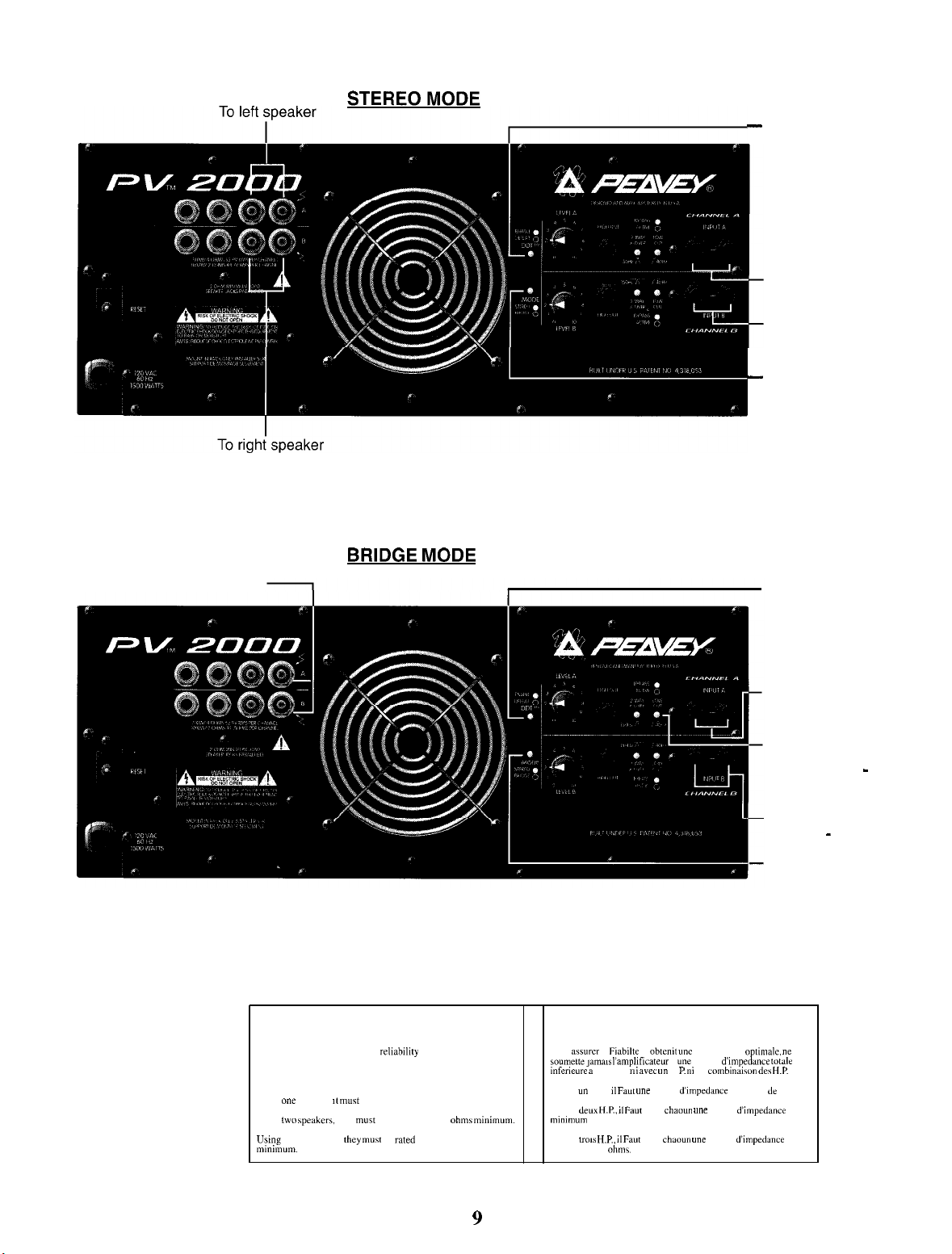
Page 9
-
DDT Compression
should be enabled
for speaker protection
Left Output
from Mixer
Right Output
from Mixer
_
Mode Switch
must be in
Stereo Position
System Load
4 OHM Minimum Speakers
BRIDGE MODE
DDT Compression
should be enabled
for speaker protection
Output from
Mixer
Optional Filter:
Depress to
eliminate Low
-
Frequency rumble
Channel B is
disabled - do not use
Mode Switch:
Must be depressed
to Bridge Position
WARNING!
For optimum performance and rehabdlty DO NOT PRESENT
THE AMPLIFIER WITH A SPEAKER LOAD OF LESS THAN
2 OHMS, ORACOMBINATION OF SPEAKERS THAT
TOGETHER ARE LESS THAN 2 OHMS!
Using
Using
Usmg three speakers, they mu\t be rated each at 8 ohms
mmirnum.
A
one
speaker, II must be rated at 2 ohms minimum.
tmw
speaker\, they must be rated each at 4 ohm\ mmimum.
9
Pour assurer la Fiabilte et obtenit
A
soumeoe,ama,s
mfeneure a 2 ohms, ni
AVEC un H.P., II Faul unr charge
AVEC
minmum
AVEC
minimum de 8 ohm\.
I’amphficateur
dew H.P., il Faut
de 4 ohms
trms H.P., II Faut
avec un
H P. ni en combmalwn de\
pour
chaoun une
pour
chaoun une
AVIS!
une
performance optlmale,
a
une
charge &mpedance
d’unpedance
charge
charge
ne
to~alr
H.P.
minimum de 2 ohms.
d’impedance
d’unpedance
Page 10

Channel A to
Low Frequency
Channel B to Mid/High
Frequency Drivers
-
2-WAY MONO
. Sub-Woofer
Level Adjust
Depress in
Crossover
Active
output
from Mixer
Connect Hi Out
to input B
Leave Switch
Out Position
Mid/High Level
adjust
IRE0
-
Sub-Woofer
Level Adjust
Depress in
Crossover
-
Active
output
-
from Mixer
-
Connect Hi Out to
Input CH A of
-
output
from Mixer
-
Depress in
Crossover
Active
-
Connect Hi Out to
Input CH B of
PVl200
PV1200
10
Page 11

Consulte
delantero en la
10s
diagramas
del panel
seccih de inglb de
este
manual.
jfelicitaciones!
PVTM
2000. Entre
filtro
subsonic0
10s
subwoofers (altavoces
altos.
Para
filtro
subsonico
diseho
de amplificadores, y aprovecha la solidez de
para
lograr una mayor confiabilidad. A diferencia de
amplificador PV 2000 utiliza transformadores de potencia masivos, enfriamiento con ventilador de
Usted
acaba de comprar el mejor amplificador de potencia de bajo
las
caracteristicas
en
cada
canal. La frecuencia
para
del
amplificador se
del
entrecruzamiento es 150 Hz, lo que
in¥
sonidos muy graves) a niveles de
evitar el indeseado ruido mecanico en el extremo de
un entrecruzamiento de
presion Sonora
10s
sonidos graves, la frecuencia
costo del
permite
extremadamente
es 40 Hz. Este amplificador utiliza tecnologia comprobada, adquirida durante
10s
dispositivos de
las
unidades
salida
con
caja
de
estereofonicas hogarehas
mundo:
dos vias
llevar a
ados
acero
TO-3
tipicas,
el
y un
del
de
el
dos
velocidades muy efectivo y ofrece impresionantes especificaciones y caracteristicas que no se
encuentran en otras unidades de la competencia con este precio. Este amplificador fue
trabajar con
salida
con el modo bridge (puente) de 4 R. El PV 2000 cuenta con una estructura resistente que
permite
conexiones en patch. El panel frontal tiene un interruptor de
indicador de
detection de la
de entrada, enchufes
vias
para las salidas
canal. Se provee un enchufe fonografico
cada
canal. El interruptor
en la parte posterior.
bridge, la
cargas
de 2 Q por canal, por lo
montarlo en un bastidor,
alimentacion
distorsion).
y otro LED doble indicador de activation
El panel posterior de
fonograficos hembra
y tambien enchufes
automatic0
anulacion del
Ademas,
sistema DDT, el filtro
este panel
asi coma
de
alimentacion
cual
desarrolla asombrosos niveles de
una capacidad sumamente adecuada
alimentacion electrica
del
compresor
cada
amplificador
de
l/4”
dobles
para
fonograficos hembra
hembra
de
l/4” para el
esta
provisto con un control
la entrada, bornes terminales de
de
l/4”
dobles
para
entrecruzamiento de alta frecuencia de
principal, que es reposicionable, tambien se
presenta
conmutadores
subsonic0
para
la selection
y el entrecruzamiento
active.
para hater
basculante, un LED
DDTTM
disehado para
ejecucion
en la
(tecnica de
la
salida
de
estereofonico/
del
cinco
cada
nivel
halla
CARACTERkTlCAS
INDICADORES
Se iluminan cuando se
panel posterior
DEL PANEL FRONTAL
LED DE
esta
DDTTM ACTIVO
esta
efectuando
(1)
compresion
en el canal. Si el interruptor
en la position anular, estos indicadores LED
en el canal.
INDICADOR
Se ilumina cuando se suministra
operativos. Si uno de
de operation seguros o su interruptor
LED DE
ALlMENTACldN (2)
alimentacion
10s canales
experimenta condiciones de
automatic0
electrica al amplificador y ambos
asociado
apaga.
CONMUTADOR DE
Se trata de un conmutador de tipo interruptor basculante
position
“O”,
se apaga el amplificador de potencia.
ALlMENTACldN (3)
para
habilitar/anular del
serialan
la
distorsion
por sobrecarga
canales estan
falla,
excede
esta
desconectado, el
10s limites
indicador
de temperatura
LED se
trabajos pesados. Al seleccionar la
11
Page 12

CARACTERhTlCAS
DEL PANEL POSTERIOR
INTERRUPTOR AUTOMAiTlCO DE
La parte posterior
interruptor se provee
a
este
contra el recalentamiento y su posible destruction
corriente de disparo del interruptor
permitir el funcionamiento con potencia de
de potencia. Normalmente, este interruptor
en el
circuit0
condiciones anormales, tales
sobrecarga o la distorsion por sobrecarga (especialmente con
automatico
interruptor
del amplificador que
se desconecte. Si
automatic0
A
del
amplificadorPVTM
para
limitar la corriente al amplificador de potencia asociado con el fin de proteger
y corrija la
Cuando el interruptor
aproximadamente un centimetro y puede ser vuelto a conectar presionando
hacia adentro. Normalmente, el
sobresale alrededor de medio centimetro. Si este tipo de interruptor “termico” se
desconecta,
despues de esperar un breve period0
A
CONECTAR EL INTERRUPTOR
INTERRUMPIR LA ALIMENTACldN.
inmediatamente
llevada a un centro de servicios calificado
para
ALlMENTACldN (4)
2000
presenta
automatic0
consuma
coma
cortocircuitos en uno o ambos
ello
ocurre, desconecte el interruptor de alimentacion, reposicione
causa
de la sobrecarga.
automatic0 esta
conectarlo nuevamente basta con presionarlo hacia adentro
cada
vez que se
de alimentacion fue escogido cuidadosamente
salida
automatic0
excesiva corriente de alimentacion. Sin embargo,
baton
un interruptor
debido
maxima continua, a la vez de proteger al amplificador
no se desconecta a menos que
desconectado, su
de un interruptor
para
AUTOMATICO,
Si el interruptor
intenta
volverlo a conectar, la unidad debe ser
a condiciones de
cargas
que se enfrie.
para
su
automatic0
canales,
RECUERDE
reparation.
la operation continua con
de 2
Q), haran
baton
sobresale
automatic0
ANTES
automatic0
de alimentacion. Este
falla.
El valor de la
para
exista
una
falla
las
que el interruptor
el
conectado
DE
VOLVER
SIEMPRE
se desconecta
Panel Posterior
CONMUTADOR DDT (5)
Este conmutador se
debe estar habilitada
recorte o sobrecarga de
derivar en la
de Peavey se describe en
CONMUTADOR DE
Este conmutador se
Toda vez que seleccione el modo bridge,
puede
en
detalle
GANANCIA DE ENTRADA (7)
Estos
controles
posible determinar
nivel de serial de entrada. La ganancia de entrada maxima (configuration de sensibilidad minima) se
logra con la perilla girada totalmente a la derecha y
sistema
totalmente girada a la derecha) produce menos ruido en el sistema y reduce la capacidad del
mezcladorkistema
desconexion
danar 10s
en secciones
para
absorber
emplea para
para
minimizar la posibilidad de que uno de
senal.
del interruptor
MOD0 (6)
emplea para
altavoces, particularmente en
siguientes
se emplean
cuan “fuerte”
picas
para
absorber
habilitar o anular el
Si la
compresion DDT esta
automatic0
detalle
en secciones
seleccionar el modo de operation
hagalo
de este manual.)
para
ajustar la ganancia de entrada a
suena
de serial. Una configuration de ganancia
picas
cada
canal del amplificador de potencia
de serial.
compresor
de alimentacion.
siguientes
con cuidado. La selection accidental de este modo
10s
sistemas biamplificados.
asi
se logra la maxima capacidad del
DDT. Normalmente, la
10s canales,
anulada, una sobrecarga
(E/ sistema
de este manual.)
estereofonico
cada
menor
o ambos, experimenten
de
o el modo bridge.
(El
modo bridge se describe
canal. De esta
para
un determinado
(la perilla no
funcion
severa
puede
compresidn
manera,
mezclador/
esta
DDT
DDT
es
12
Page 13

ENCHUFES
Se
proveen
Esto
permite
ser
empleado coma “salida”
amplificador u otros amplificadores o equipos. Estos enchufes
masa con el
cada
entrada. Esta caracteristica
en patch con cables de
10s
de otros equipos varios que
equilibradas
utilizar un enchufe macho
negativa y el manguito conectado a tierra. Se puede utilizar un enchufe macho
cual crea
HEMBRA DE ENTRADA DE
dos enchufes
que uno sea utilizado
chasis
y
electronicamente para
una entrada no equilibrada.
hembra estereofonicos
coma
(cable en Y)
preven
un
circuit0
permite
l/4”
relativamente cortos entre
comparten el
eliminar aun
estereofonico
ALTA
una entrada conventional y, simultaneamente, el otro pueda
para
cerrado
la “operation libre de zumbidos” cuando se
de
IMPEDANCIA
de
l/4”,
la conexion a otro enchufe
exclusive
10s
mismo bastidor. Las entradas estan realmente
mas
cualquier zumbido. En la entrada es posible
l/4”,
con el extremo
(8)
en paralelo,
hembra
de elimination por puesta a tierra, asociado a
enchufes
para
la entrada a
hembra
de entrada no estan puestos a
hembra
coma
fase positiva, el
de entrada de este
de este amplificador, y con
monofonico
cada
canal.
hacen
conexiones
anillo coma
de
i/4”,
fase
lo
ENCHUFES
Estos enchufes
conmutador de entrecruzamiento
automaticamente al canal A. La
enchufe
frecuencias bajas
salida
alta
de dos vias.
SALIDAS A
A
CABLE DE ALlMENTACldN ELECTRICA -
HEMBRA DE SALIDA
hembra
hembra
hasta la entrada del canal B. Si ambos
deben
ser conectados a otro amplificador
LOS ALTAVOCES (10)
Para cada
terminales de
estan en paralelo y, por lo
terminar con enchufes macho estereofonicos de
banana o con conductores pelados
de
se recomienda utilizar
debe
adecuadamente conectada.
de
(tanto
en el modo bridge
canal se
cinco
vias.
proceder
ALTA DEL
salida
se
proveen para
esta
presionado hacia adentro, la
seAal
de alta frecuencia debe ser conectada en patch desde este
proveen
cinco
vias
coma
Para
aplicaciones que emplean alta potencia en forma sostenida,
10s
bornes terminales de
con cuidado
ENTRECRUZAMIENTO (9)
brindar capacidad de entrecruzamiento. Si
canales
coma
en el modo
para proveer las
dos enchufes
conectores de
tanto, 10s
para
cables de conexion a
para
asegurar que
Productos de 120 V
estereofonico), 10s
hembra
salida.
ser utilizados con
10s
el
sefial
de baja frecuencia es guiada
se estan empleando
enchufes
frecuencias agudas en un sistema
de
l/4”
y dos bornes
Nuevamente, estas salidas
10s
altavoces pueden
l/4”,
con enchufes macho tipo
10s
bornes terminales
cinco
vias. Sin embargo, se
altavoces tengan la fase
solamente (11)
para las
hembra
de la
Todos
unico
A
Es preferible evitar emplear cables prolongadores; sin embargo, si
cable de tipo trifilar con conductores calibre AWG NC 14 por lo menos. El
diametro
choque
a tierra.
electrico
con un enchufe macho de CA conventional provisto de una clavija de conexion
a tierra. La conexion debe realizarse a un
soportar
las
tomacorriente no tiene alojamiento
adaptador que libere la clavija de
tierra adecuadamente. Nunca retire
fue provista para su seguridad.
limita
seriamente la capacidad de potencia de este amplificador.
10s
amplificadores de potencia de la serie PV estan equipados con un
cable de conexion a la
hasta 15 A o
aplicaciones que utilizan alta potencia en forma continuada. Si
o incendio,
asegurese
mas
linea para
en forma continuada. Esto tiene importancia
siempre de que el amplificador
servicio pesado, de tres conductores,
circuit0
para
la
toma
de tierra y conectar el
la
clavija de tierra en
independiente que pueda
toma
de tierra, es
ello
es necesario,
este
13
critica
en
el
precise
ningh
empleo
Para
adecuadamente conectado
utilizar un
tercer
cable a
equipo. Ella
utilice
siempre
de cables de
evitar el riesgo de
menor
Page 14

CONMUTADOR DEL
ENTRECRUZAMIENTO
(12)
Este conmutador se utiliza
se deprime este
baton, las
frecuencias altas se envian al enchufe
entrada de
10s
otros
canales
para
activar la capacidad de entrecruzamiento de este amplificador. Cuando
frecuencias bajas se envian automaticamente al canal correspondiente. Las
hembra
de
salida
de alta frecuencia, que se puede conectar a la
o a otro amplificador. La frecuencia de entrecruzamiento fue fijada en 150
Hz.
CONMUTADOR DEL FILTRO
SUBSdNlCO
(13)
Al deprimir este conmutador (hacia adentro), se conecta un filtro pasabanda alta de 40 Hz del
respective
contra la posibilidad de superar el recorrido utilizable con su
frecuencia es de 18 dB por
INSTALACldN Y CONEXldN
La serie PV de amplificadores de potencia profesionales
instalaciones comerciales y ofrece la calidad de funcionamiento requerida
de
grabacion
cada
de nivel,
ubicados en el panel posterior. El panel frontal contiene indicadores LED de
activation del
canal. Esto
una de
10s
recorta las
frecuencias extremadamente bajas, protegiendo a
nucleo.
La
octava.
esta disenada para
y en el hogar. Estas unidades tienen una altura estandar
ellas
es enfriada por un ventilador
conmutadores selectores y el interruptor
circuit0
DDT, asi
coma el
interruptor principal de
interno
de dos etapas
automatic0
de
alimentacion electrica.
alimentacion
10s
altavoces
atenuacion
progresiva de baja
ofrecer durabilidad en
para
aplicaciones en estudios
para
montaje en bastidores y
automatico. Ademas, 10s controles
electrica estan
alimentacion
electrica y de
INSTALACIONES INDUSTRIALES Y COMERCIALES
Para las
sostenida,
dejar un espacio de bastidor libre entre
aire
montado en bastidor, debe recibir una cantidad adecuada de
contar
con “baja velocidad” y, normalmente,
operation sostenida con altos niveles de alta potencia. Luego, a medida que
se calientan, el
las
puede
muy normal. Si el enfriamiento es inadecuado
en el
amplificador
amplificador puede apagar temporariamente la unidad.
enfriamiento disponible, la operation se reiniciara de
indicador
causa
flujo
medidas
mas fresca
instalaciones comerciales y otras donde se requiere operar con alta potencia en forma
10s
amplificadores
de la parte posterior y expele el
con una fuente de
aire
deben
montarse en bastidores de
cada
amplificador de la pila, dado que
aire
caliente por el frente. Sin embargo, cuando el amplificador
que no
haya
sido precalentado por otros equipos. El amplificador arranca
permanece
en operation a baja velocidad a menos que
19”
(48 cm) estandar. No es necesario
cada
aire
“FRESCO”. El ventilador
10s
circuit0
condiciones de la
continuar
flujo
de
o entrar en un ciclo
aire debido
esta
LED de
del apagado termico. Si el amplificador no
de
aire
es normal
para proveer
sea la temperatura de operation de un
de sensado termico
serial
y de la
carga
continua
al bloqueo de
hate
funcionar el ventilador en alta velocidad. En
del amplificador, la operation del ventilador a alta velocidad
alternando entre velocidades alta y baja. Esta situation es
debido
al
aire
precalentado, o se produce una reduction
10s
orificios de
admision/escape
del amplificador, o bien si
severamente sobrecargado o en cortocircuito, el sistema de sensado termico del
alimentacion.
tanto
hacia adentro
un ambiente
En cualquier
coma
mas
frio
Segun cual
manera
case,
es
precise actuar
esta
severamente sobrecargado o en cortocircuito y
hacia afuera del amplificador, se
para
todos
10s
amplificadores. Como regla general,
sea la cantidad de
relativamente
correctivamente
rapida
equip0 electronico, tanto mas
servicio.
ventilador succiona
interno
haya
“disipadores de
funcion
aire
de
y se iluminara
para
determinar la
deben
adoptar
larga
sera
su vida de
esta
debe
una
calor”
de
el
el
el
cuanto
14
Page 15

INSTALACIONES EN EL
ESTUDIO Y EN EL HOGAR
En la mayoria de
las
aplicaciones de
potencias
medias y bajas, el amplificador de potencia puede estar
montado en cualquier configuration. Se recomienda que, de ser posible, el amplificador de potencia se
coloque en la parte superior de una pila de equipos. De esta
recalentamientos de equipos sensibles
potencia. Como regla general, la mayoria de
debido
al
aire
caliente que se eleva desde el amplificador de
10s
requisitos de
estudio nunca motivan la operation del ventilador a alta velocidad. Sin embargo, si
posible que se trate de una indication de que no se han dado
enfriamiento adecuado. Recuerde: si
10s
amplificadores de potencia de la serie PV
manera,
las
se evitan posibles
aplicaciones en el hogar y en
ello
10s
pasos necesarios
para proveer
estan
el
ocurre, es
un
encerrados en
un gabinete, pueden tener problemas de enfriamiento severos, aun con niveles de potencia bajos. Una
vez
mas, el
termico temporal y/o la
Asimismo, la mayor
sobrecarga
alimentacion
MOD0
La operation y el
menudo
en el modo bridge,
suma
nominal del canal
nominal del modo bridge son 2000
efectua
positivo del altavoz en el borne de
en el borne de
funciones de entrada al canal B quedan anuladas y, en esas condiciones, no sirven
proposito.
de
difusion
cuando se requieren niveles de potencia muy altos
gabinetes normalmente contienen dos o cuatro altavoces
emplear el modo bridge, la impedancia del gabinete debe ser 4 u 8 Q
cortocircuito inadvertido o el uso sostenido con sobrecargas pueden
desconexion
par-te
de
severa, el equip0
10s
PV 2000 puede dar lugar a la desconexion de un interruptor
del interruptor
cableados y
automatic0
de la
circuitos hogarerios
alimentacion
son solo
para
provocar el
apagado
electrica principal.
15 A. Si se produce una
automatico
de 15 A.
BRIDGE (PUENTE)
son
mal
de
las potencias
empleo
interpretados. En terminos
reales del modo bridge (puente) en
basicos,
este
se convierte en una unidad de un solo canal con una potencia nominal igual a la
nominales de ambos
unico.
Por ejemplo, el PV 2000 tiene 1000
W,r
canales
sobre 4 Q
cuando un amplificador de dos
y con una
(carga
10s
amplificadores
carga
nominal que duplica la
Wef
nominales por canal sobre 2 R. El valor
estereofonicos
canales
se opera
carga
a
minima). La operation en el modo bridge se
colocando el conmutador de modo en la position “BRIDGE”, conectando el terminal del cable
conexion
conexion
rojo del canal B y
rojo del canal A, el terminal del cable negativo del altavoz
usando el
canal A
coma
canal de entrada. Todas
las
para ningun
El modo bridge tambien se suele emplear
muy grandes. Otro
empleo comun para el
para
alimentar sistemas de
modo bridge es la
para reproducir
frecuencias muy bajas. Estos
para manejar 10s
-inunca
sonido
en aplicaciones
aplicacion
con subwoofers
niveles de potencia.
inferior a 4
Para
LR!
de
DDT
El
circuit0
tecnico de
que el amplificador de potencia se quede sin margen
sobrecarga). Este
condiciones de
ganancia del amplificador) cuando la
compresion
control de
para reproducir
posibilidad de el altavoz se degrade o se
automatic0
amplificadores de potencia utiliza interruptores de
contra la corriente excesiva, el sistema de
para el
recorte de la serial. La operation continua con
automatico
esta
de
compresion DDT
sonido
maximizar el
(tecnica de detection de
desempeno
de la combination
para
circuit0
las senales
es, por lo
umbral.
del
Esta tecnica utiliza efectivamente
la
sefial,
problema
de
compresion
es activado mediante un
que pueden sobrecargar el amplificador y
tanto,
la
distorsion
distorsion
por sobrecarga en si misma y por
por sobrecarga es inminente. El
cada
a la vez que minimiza el recorte y la
daAe
queda reducida. El sistema
de la
distorsion
por sobrecarga del amplificador. Dado que la serie PV de
alimentacion automaticos para
compresion DDT desempena
funcionamiento en forma continuada, evitando en
distorsion
se desconecte; no obstante, si el
razon, usted
debe siempre tener el sistema de
circuit0 DDT esta
compresion DDT
15
distorsion)
absorber
patentado de Peavey
amplificador/altavoces,
picas
de potencia
circuit0 exclusive
activa
la
que sensa
compresion
umbra1
ello
no se utiliza
permite
al
a la vez de evitar
(distorsion
por
las
(reduce la
de la
ningun
vatio del amplificador de potencia disponible
distorsion
de la
DDT
seAal.
De esta
manera,
representa un enfoque
la
brindar protection
un rol incluso
cada
canal la
distorsion
por sobrecarga
activado, este
hate
que el interruptor
problema
mas
importante
por sobrecarga y
se minimiza. Por
el
habilitado.
Page 16
situ6
Veuillez
vous
rkf&er au “front panel art”
dans la section en langue
anglaise de ce
manuel.
Felicitations ! Vous venez d’acheter le meilleur amplificateur de puissance a bas prix du monde,
PVTM
2000. Cet amplificateur est dote d’un crossover a 2 voies et d’un filtre subsonique pour chaque
canal. La
d’extremes
40 Hz pour
technologie eprouvee acquise
robustes dispositifs de sortie en boitier
chaine
refroidissement a ventilateur deux vitesses
introuvables sur les amplis de la concurrence dans la
concu
impressionnant. Le PV 2000 peut
des
bascule, une DEL temoin de mise
de chaque amplificateur est dote d’une
d’entree de
de
6,3
crossover
panneau arriere, de
filtre subsonique et de crossover
FONCTIONNALITliS DU
frequence
graves a des pressions acoustiques incroyablement
empecher
Hi-Fi typiques, le PV 2000 est dote de transformateurs d’alimentation
de crossover est
fixee a
150 Hz, ce qui
tout bourdonnement de basse
au fil de longues annees de conception d’amplificateurs,
acier
TO-3, assurant sa fiabilite. A I’encontre des amplis de
tres efficace,
permet
frequence.
de faire travailler les haut-parleurs
elevees.
Le filtre subsonique est
Cet appareil, qui s’appuie sur une
massifs
et offre des caracteristiques et
meme
gamme de prix. Cet ampli
beneficie
et d’un
fonctions
etant
pour une charge de 2 ohms par canal, le niveau de performance en mode de pontage 4 ohms est
possibilites
mm
de
6,3
mm
(i/4 PO.).
hautes-frequences
cablage
plus qu’adequates. Le panneau avant
(l/4 PO.),
de sorties 5 voies a bornes serre-fil et de deux jacks telephone de sortie
II comprend
de chaque canal. Le disjoncteur general rearmable se trouve aussi sur
meme
que le selecteur
etre monte
sous
egalement
en rack et presente une construction robuste, ainsi que
comporte
tension et une double DEL temoin
commande
un jack telephone de
stereo/pontage
de niveau d’entree et de deux jacks telephone
6,3
et les commutateurs d’annulation
un commutateur general a
mm
DDTTM.
(l/4 PO.)
Le panneau arriere
de sortie pour
actif.
PANNEAU AVANT
le
de
initialement
DDT,
fixe
le
de
a
le
DEL D’ACTIVATION
S’allume lorsque la compression
DDTTM
(1)
DDT
est active sur le canal. Lorsque le commutateur Enable/Defeat
(Activation/D&activation) du panneau arriere est en position de d&activation, cette DEL indique
I’ecretage
DEL
S’allume lorsque I’ampli est
defaillance, de depassement de la temperature
du canal.
D’ALIMENTATION
(2)
sous
tension
c.a.
et que
maximale
res
deux canaux sont operationnels. En cas de
ou d’ouverture du disjoncteur de I’un ou
I’autre des canaux, cette DEL s’allume pour signaler I’existence du probleme.
COMMUTATEUR
Commutateur a bascule. En position
FONCTIONS DU PANNEAU
DISJONCTEURS
Un disjoncteur se trouve sur le panneau arriere du
transformateur d’alimentation auquel il est
tion
causee
par un defaut interne de I’amplificateur. Les seuils de declenchement ont
soigneusement
MARCHE/ARRET
ARRIkRE
(4)
calcules
pour permettre le fonctionnement
(3)
<<
0
>>,
I’ampli de puissance est eteint.
2000.
PVTM
affecte afin
de le proteger
II sert a limiter le courant du
continu
contre
toute surchauffe ou destruc-
ete
tout en protegeant le transformateur
d’alimentation. Normalement, ces disjoncteurs ne s’ouvrent que si un defaut de circuit de I’amplificateur
preleve
une quantite excessive de courant. Toutefois, des conditions anormales, telles qu’un
court-
16
Page 17
circuit dans I’un ou les deux canaux, le fonctionnement
(particulierement en 2 ohms) causent le declenchement du disjoncteur. Dans ce cas, il suffit de mettre
I’interrupteur general en position
d’art@,
de rearmer le disjoncteur et d’eliminer la cause de la surcharge.
continu
en surcharge ou en
ecretage
Lorsque le disjoncteur se declenche, le
pour se rearmer. Normalement, le
A
Panneau arrikre
COMMUTATEUR DDT
Ce commutateur
doit etre activee
DDT
est
desactivee,
fonctionnement. (Le fonctionnement du
plus loin dans ce
COMMUTATEUR DE MODE
Ce commutateur
doit etre
parleurs, particulierement en cas de bi-amplification. (Le mode de pontage est
plus loin dans ce manuel.)
active
6 mm. Si ce (( thermorupteur
quelques instants puis de I’enfoncer pour le rearmer.
ETEINDRE
declenche immediatement chaque fois que vous essayez de le rearmer, I’appareil
etre confie
permet
pour reduire les risques
une forte surcharge peut causer le declenchement des disjoncteurs pendant
manuel.)
permet
avec
prudence. La selection accidentelle de ce mode peut endommager les
L’AMPLI
a un centre de reparation qualifie.
(5)
d’activer ou de desactiver le compresseur
(6)
de choisir le mode de fonctionnement stereo ou pontage. Le mode de pontage
AVANT DE
>>
se declenche, il suffit de de le laisser refroidir pendant
RkARMER LE
d’ecretage
syst.+me
de compression DDT est
bouton
bouton
ou de surcharge de I’un ou des deux canaux. Si la
sort d’environ
de rearmement depasse d’approximativement
N’OUBLIEZ PAS
DISJONCTEUR. Si
DDT.
2,5
Normalement, cette
expliqk
cm et
d&-it
doit etre enfonce
DE
le
disjoncteur se
de
faGon d&aMe
de
faGon d&ai//be
TOUJOURS
doit
fonction
le
haut-
GAIN
D’ENTREE (7)
Ces
commandes
determinent le <c volume >> de chacun des canaux de I’ampli pour un niveau de signal d’entree donne. Le
gain d’entree maximal
vers la droite, ce qui donne une marge de
le bouton
de
JACKS
Chaque canal est dote de 2 jacks d’entree stereo
ainsi servir d’entree conventionnelle et I’autre de (c sortie ligne >>
d’un autre jack d’entree sur cet amplificateur ou d’autres amplis et equipements. Ces jacks de
(l/4 PO.)
unique, associe
si des cables de raccordement de
divers autres appareils montes sur le
reduire encore davantage le ronflement. Un jack stereo de
la pointe
mm
JACKS DE
Ces jacks de sortie sont
signal basses
etre branche
frequences
relies a un autre amplificateur
n’est pas tourne a fond vers la droite, le bruit de fond est reduit,
securite.
D’ENTREE HAUTE
ne sont pas mis a la masse sur le chassis et
etant
(l/4 PO.)
permettent de
(sensibilite
avec
chaque entree. Cela
la phase positive, I’anneau la phase negative et la tige, la masse. Un jack mono de
peut egalement servir a
SORTIE
frequences
sur
(en mode de pontage ou stereo), les jacks HI OUT (sortie hautes
CROSSOVER
I’entree
concus
est automatiquement
du canal B a partir de ce jack. Si les deux canaux sont
regler le
nominale minimale) est obtenu lorsque le
IMPCDANCE
pour le crossover. Lorsque le commutateur de crossover est
afin
gain d’entree de chaque canal. Par consequent,
bouton
est tourne a fond
securite
(8)
permet
6,3
mm
(l/4 PO.)
meme
rack. Les entrees sont
creer
une entree asymetrique.
HAUTES
d’obtenir la separation des aigus sur un systeme a 2 voies.
console de
paralleles
offrent
normalement un fonctionnement << sans ronflement
relativement courts sont
FRlhUENCES
achemine
melange/sonorisation
mais
de
6,3
mm
(l/4 PO.).
(avec
une bretelle) pour le branchement
un circuit d’elimination de boucle de masse
utilises
equilibrees
6,3
mm
(l/4 PO.)
(9)
au canal A. Le signal hautes
peut
maximale. Lorsque
au detriment de la marge
L’un des jacks peut
entre cet ampli et
electroniquement pour
etre utilise
utilises
frequences)
pour les basses
elles
6,3
sur
enfonce, le
frequences doit
peuvent
mm
>>
I’entree,
6,3
etre
17
Page 18
SORTIES
A
HAUT-PARLEURS (10)
Chaque canal est pourvu de deux jacks de
raccordement 5 voies a bornes serre-fil. Ici encore, les sorties de chaque canal sont en
parallele,
banane ou des fils denudes pour le branchement des haut-parleurs. L’usage des bornes
serre-fil est recommande pour les applications a haute puissance continue, a condition
toutefois de veiller a ce que le branchement assure la mise en phase
parleurs.
ce qui
permet
d’utiliser des jacks telephone de
6,3
mm
(l/4 PO.)
6,3
et d’une barrette de
mm
(l/4 PO.),
des fiches
correcte
des
haut-
CORDON
A
Le
recours
utilisez toujours un cordon a 3 conducteurs d’un calibre minimum de 14 AWG. L’usage de conducteurs
plus faibles limiterait considerablement la
appel a un
risques de
a la terre.
COMMUTATEUR DE
Ce commutateur
basses
sont envoyees au jack de sortie hautes
du canal,
COMMUTATEUR DE FILTRE
En position enfoncee, ce commutateur
Cela coupe les
membrane excessif. L’attenuation des basses
D’ALIMENTATION
Tous
les amplificateurs de puissance
haute
capacite a
sur un circuit independant capable de supporter au moins 15 amperes en
est particulierement important pour les applications a haute puissance continue. Si la
prise secteur n’est pas
approprie
broche de terre d’un appareil, quel qu’il soit. Elle assure votre securite.
a des rallonges
electricien qualifie
choc
electrique ou d’incendie, assurez-vous toujours que I’amplificateur est correctement mis
CROSSOVER
permet
frequences
soit
sont automatiquement acheminees au canal correspondant. Les hautes
a un autre ampli. La
frequences
c.a.- Modeles 120 V
3 fils et d’une fiche standard
dotee
d’une broche de terre, un adaptateur de mise a la terre
doit etre
doit,
d’utiliser la
ultra-basses
utilise, son fil
dans la
pour I’installation de tout nouvel equipement electrique. Pour eviter les
SUBSONIQUE
mesure
capacite
(12)
fonction
frequences
frequence
fournit
afin
du possible,
de crossover de I’amplificateur. Lorsqu’il est
de crossover est
(13)
un filtre passe-haut de 40 Hz au canal correspondant.
de proteger les haut-parleurs
frequences
seulement (11)
serie
PV sont
etant
correctement
etre evite.
de puissance de cet amplificateur. Faites toujours
(HI OUT), lequel peut
est de 18 dB par octave.
equip&
avec
broche de terre. II
relic
fixee
a 150 Hz.
d’un cordon d’alimentation
a la terre. Ne
Toutefois, en cas de besoin,
etre relic soit
contre
doit etre branche
continu.
retirez jamais la
enfonce,
frequences
a I’autre entree
un mouvement de
Cela
les
INSTALLATION ET BRANCHEMENT
Les amplificateurs professionnels de la
commerciales
studio. Ces appareils presentent la hauteur de montage en rack standard et sont refroidis par un
ventilateur automatique interne a deux vitesses. Toutes les connexions d’entree et de sortie se trouvent
sur le panneau arriere, qui
disjoncteurs rearmables. Le panneau avant est dote des temoins DEL de mise
d’activation
INSTALLATIONS INDUSTRIELLES ET COMMERCIALES
Pour les installations
les amplificateurs doivent
laisser un
rejette I’air
amplificateurs montes en rack. Les ventilateurs internes doivent disposer d’une source d’air qui nest
pas chauffe par d’autres equipements. A la mise
et y reste a moins que des niveaux
et
offrent le
du systeme DDT, ainsi que du commutateur general.
espace
entre les amplis,
chaud
par I’avant. Toutefois, une source d’air<<
niveau de performances requis pour les applications residentielles ou de
comporte
commerciales
etre
montes sur un rack standard de 48 cm (19
serie
PV sont
egalement les
ou autres exigeant un fonctionnement a haute puissance
etant donne
eleves
que chaque ventilateur aspire I’air frais de I’arriere et
de puissance continue se presentent. Dans ce cas,
concus
commandes
sous
tension, le ventilateur demarre en basse vitesse
pour
etre
durables dans les installations
de niveau, les selecteurs et les
sous
tension et
PO.).
II n’est pas necessaire de
FRAIS )) doit etre
prevue pour les
continu,
le
18
Page 19

<<
radiateur >) de I’ampli chauffe et le circuit de detection thermique automatique fait passer le ventilateur
en haute vitesse. Selon la puissance du signal et la charge de I’amplificateur, le ventilateur continue de
tourner a haute vitesse ou alterne entre les vitesses haute et basse.
refroidissement est insuffisant du fait du prechauffage de I’air, si une reduction du debit d’air se produit
Ceci
est tout a fait normal. Si
le
a
la suite de I’obstruction des ouvet-tures d’admissionkvacuation, ou si I’amplificateur est serieusement
surcharge ou court-circuit& le systeme de detection thermique peut eteindre I’appareil temporairement.
Selon la quantite d’air de refroidissement disponible, I’amplificateur devrait se rallumer relativement vite,
ce qui est indique par I’illumination de la DEL de mise
appropriees doivent
pas serieusement surcharge ou
necessaires doivent
regle g&&ale,
duke
de vie utile est longue.
etre
prises pour determiner la cause de
court-circuit6
etre
prises pour procurer un environnement plus frais a
et que la circulation d’air est
plus I’environnement dans lequel un equipement electronique est
sous
tension. Dans
I’arret
tous
les cas, les mesures
automatique. Si I’amplificateur n’est
normale,
tous
les dispositions
les amplificateurs. En
utilise
est frais, plus sa
INSTALLATIONS RESIDENTIELLES ET DE
Pour la plupart des applications basse et moyenne puissance, I’amplificateur de puissance peut
monte
dans n’importe quelle configuration. II est toutefois preferable, dans la
placer en haut dune pile d’appareils. Cela
causee
par la chaleur emanant de I’ampli de puissance. En
STUDIO
mesure
evite
les risques de surchauffe des appareils sensibles,
regle generale,
I’utilisation residentielle ou
du possible, de
etre
le
en studio ne cause jamais le declenchement de la haute vitesse du ventilateur. Cependant, le passage
en haute vitesse peut indiquer que les mesures necessaires n’ont pas
ventilation adequate. N’oubliez pas que s’il est enferme dans une armoire, un amplificateur de
presentera de
court-circuit
thermorupteur
serieux problemes
accidentel
et/au
ou une surcharge prolongee peuvent causer
declencher les disjoncteurs d’alimentation. D’autre part, la plupart des
de refroidissement,
meme a
bas niveau de puissance. Ici encore, un
circuits residentiels sont de 15 A. En cas de surcharge serieuse, un PV 2000 peut causer
ete
prises pour assurer une
I’arret
automatique par
serie
le
cablages
le
PV
et
declenchement d’un disjoncteur de 15 A.
MODE DE PONTAGE
En
realite, le
generalement mal compris.
pontage, il est
charge nominale double de
fonctionnement et I’usage du mode de pontage des amplificateurs stereo sont
converti
En termes simples, lorsqu’un amplificateur stereo est
en mono et sa puissance nominale devient la somme des deux canaux
celle
de chacun des canaux stereo. Par exemple, la puissance nominale du
utilise
en mode de
avec
une
PV 2000 est de 1000 watts RMS en 2 ohms. La puissance nominale en pontage est de 2000 watts RMS
en 4 ohms (charge minimale). Le fonctionnement en mode de pontage est obtenu en mettant
commutateur de mode en position (<BRIDGE
rouge du canal A et le fil negatif a la borne rouge du canal B ; le canal A
Toutes les
fonctions
d’entree du canal B deviennent alors inoperantes. Une autre application du mode
>>,
ce qui
connecte le
fil
positif
du haut-parleur a la borne
sert
alors de canal d’entree.
de pontage est I’alimentation de systemes de distribution du son sur les sonorisations de
taille. Ce mode est egalement couramment
graves ou des niveaux de puissance
tres
utilise
pour I’alimentation des haut-parleurs d’extremes
&eves sont requis pour reproduire les
frequences
tres
le
grande
extremement basses. Les enceintes abritent alors 2 ou 4 haut-parleurs pour supporter les niveaux de
puissance utilises. En mode de pontage, I’impedance
ohms
!
doit etre
de 4 ou 8 ohms - jamais inferieure a 4
DDT
Le circuit de compression
I’ingenieur
sance
circuit exclusif qui
du son d’optimiser le rendement
d’etre
a court de marge de
detecte
compression (reduit le gain de I’ampli) lorsque
alors de
lui-meme
et aucune
efficacement chaque precieux watt a la disposition de I’amplificateur de puissance pour reproduire
DDT
(technique de detection de distorsion) brevete de Peavey
amplificateur/haut-parleurs
securite (ecretage).
les conditions de signal
I’ecretage
commande
de seuil particuliere n’est utilisee. Cette technique utilise
Ce systeme de compression est active par un
susceptibles
de
est imminent. Le seuil de compression
en
empechant
surcharger
I’amplificateur et active la
permet
a
I’ampli de puis-
s’ecrete
le
19
Page 20

signal tout en minimisant
degradation et d’endommagement des haut-parleurs. Le systeme
automatique au
disjoncteurs pour la protection
pour le maintien du fonctionnement en
Bien que le fonctionnement
au DDT, ce
active.
probleme d’ecretage
probleme
est
I’ecretage
contre
prolonge
minimise.
et la distorsion, reduisant ainsi considerablement les risques de
DDT constitue
des amplis de puissance. Les amplis de
les surtensions, le
empechant I’ecretage
en
Crete
puisse causer le declenchement des disjoncteurs, grace
C’est pourquoi le systeme de compression
role
du systeme
et la surcharge de chacun des canaux.
une solution
serie
PV utilisant des
DDT
est encore plus important
DDT
devrait toujours
etre
20
Page 21

Siehe
Diagramm
der
Frontplatte im englischen
Teil des
Handbuchs.
Herzlichen
Leistungsverstarker der Welt erworben. Zu seinen Merkmalen
und ein Unterschallfilter
Subwoofer mit extrem
eine feste Grenzfrequenz von 40 Hz,
unterdrticken.
der Konstruktion von Verstarkern stammt, wobei die
Zuverlassigkeit gewahrleisten. Anders
Netztransformatoren und eine
beeindruckende technische Kennwerte und Merkmale, die man
Preisklasse vergeblich
mit
tiberwaltigenden
ein robustes, zur Rackmontage geeignetes
An der Geratevorderseite sind ein Netzschalter, eine Betriebs-LED und zwei
Aktivierung vorhanden. Die
Klinkeneingangsbuchsen, Ftinfwege-Klemmschraubenausgange und zwei 6,3-mm-Klinkenausgange
jeden Kanal.
Auch
der
Ruckseite
Frequenzweiche vorhanden.
GERATEVORDERSEITE
Gluckwunsch!
Dieser Verstarker verwendet erprobte
Fur
die Hochfrequenzweiche jedes Kanals ist eine
rtickstellbare
Schalter
Mit dem
fur
jeden Kanal. Die Ubergangsfrequenz ist fest auf 150 Hz eingestellt, so
hohen
sucht.
Leistungspegeln im 4
Gerateruckseite
Netzunterbrecherschalter befindet
fur
Stereo-/Uberbriickungsbetrieb, DDT-Deaktivierung, Unterschallfilter und
PVTM
2000
Schalldruckpegeln angesteuert werden
urn unerwunschtes
als
typische Heimgerate
auf3erst
Dieser Verstarker ist
wirksame
Ohm-Uberbruckungsmodus
Gerat
verfiigt
haben
Sie einen der
Rumpeln im unteren Frequenzbereich zu
Technologie,
robusten
Geblasektihlung
fur
2 Ohm Belastung pro Kanal ausgelegt, so
mit mehr
tiber
einen Eingangspegelregler, zwei
besten
und preisgijnstigsten
gehoren
TO-3 Ausgangseinheiten
verftigt
als
ausreichenden
6,3-mm-Klinkenbuchse
sich
an der
eine Zweiwege-Frequenzweiche
konnen.
die
aus
der PV 2000 iiber massive
mit zwei Drehzahlen. Er bietet
bei
vergleichbaren Get&en dieser
aufwarten kann. Der PV 2000 ist
Riickseite. AuBerdem
Der Unterschallfilter hat
langjahrigen Erfahrungen in
AnschluBmoglichkeiten.
LEDs fur
hochste
die
DDTTM-
6,3-mm-
vorhanden.
sind an der
daB
daB
er
fur
LEDS FUR
Diese LED leuchtet, wenn DDT-Kompression im Kanal erfolgt.
Schalters an der
BETRIEBS-LED (2)
Leuchtet, wenn der Verstarker mit Spannung versorgt wird und beide
einer der
einen der
auf dieses Problem hinzuweisen.
NETZSCHALTER (3)
Dies ist ein robuster Kippschalter. In der Position
GERATERUCKSEITE
UNTERBRECHERSCHALTER (4)
An der
zugehorigen Netztransformator begrenzt,
schutzen.
Ausgangsleistung
werden diese Unterbrecher nur dann
DDTTM-AKTIVIERUNG
Gerateruckseite
Kanale
Ruckseite
Die Werte fur den Auslosestrom wurden
fehlerhaft arbeitet oder die sichere Betriebstemperatur
Kanale
der
des
moglich
zugehorige
PVTM
2000 befindet
ist und der Netztransformator trotzdem
(1)
auf
,,Defeat”
Unterbrecherschalter
ausgelost,
zeigt diese LED Ubersteuerung im Kanal an.
sich
ein Unterbrecherschalter, der den Strom zum
urn
ihn vor Uberhitzung und
wenn ein Fehler in den Verstarkerschaltungen auftritt
Bei
Einstellung des
Kanale
ausgelost
,,O”
ist der Leistungsverstarker ausgeschaltet.
sorgfaltig
wurde, erlischt die Betriebs-LED,
moglicher
so
gewahlt, daf3
geschutzt
Enable/Defeat-
betriebsbereit sind. Wenn
uberschreitet,
Dauerbetrieb mit
wird. Normalerweise
oder wenn
Beschadigung zu
hoher
fur
urn
21
Page 22

und
ubermaf3ig
beiden
konnen
Kanalen
bewirken,
Spannungsversorgung
Strom aufgenommen wird. Abnormale Bedingungen, wie ein
oder Dauerbetrieb mit Uberlastung oder Ubersteuerung (insbesondere an 2 Ohm),
daf3
der Unterbrecher ausgelost wird. Sollte dies vorkommen, schalten Sie die
aus
Ursache der Uberlastung.
und stellen Sie den Unterbrecher
zuruck.
KurzschluB
Beheben Sie
in einem oder
anschlief3end
die
Wenn der Unterbrecher
Zur
Rtickstellung
wird der Knopf hineingedriickt. Normalerweise steht der Rtickstellknopf
etwa 6 mm hervor. Wenn dieser thermische Unterbrecher ausgelost wird,
Gerat abktihlen
UNBEDINGT DIE
UNTERBRECHER ZURUCKSTELLEN.
Zurtickstellen
und driicken Sie dann den Knopf wieder hinein.
wieder ausgelost wird, sollte das
ausgeldst
SPANNUNGSVERSORGUNG AUS,
wird, steht der Unterbrecherknopf etwa 12 mm hervor.
Wenn der Unterbrecher gleich
Get-at
von einer Kundendienststelle
SCHALTEN SIE
BEVOR SIE
DEN
lassen
nach
Sie das
dem
iiberprtift werden.
GERliTERiiCKSElTE
DDT-SCHALTER
Dieser Schalter dient zum Ein- und Ausschalten des DDT-Kompressors. Normalerweise sollte die
Funktion eingeschaltet sein,
Kanale
minimal zu
die Netzunterbrecher ausgelost werden. (Das Peavey
(5)
halten. Bei
urn
das Risiko einer Ubersteuerung oder Uberlastung eines oder beider
ausgeschaltetem
DDT
kann eine extreme Uberlastung dazu
DDT-Kompressionssystem wird
ftihren, daf3
sp2ter in dieser
DDT-
Anleitung ausftihrlicher behandelt.)
MODUSSCHALTER
Dieser Schalter dient zur Wahl des Stereo- oder
Uberbrtickungsmodus gewahlt
dieses Modus
Verstarkern. (Der iiberbrtickungsmodus
konnten
(6)
Uberbruckungs-Betriebsmodus.
wird,
muf3
mit Sorgfalt vorgegangen werden.
die Lautsprecher beschadigt werden, vor
wit-d spiiter
in dieser Anleitung ausfiihrlicher behandelt.)
allem
in
Systemen
Wenn der
Durch
versehentliche Wahl
mit zwei
EINGANGSVERSTiiRKUNG
Diese Regler dienen zur Einstellung der Eingangsverstarkung der
,,laut”
jeder Kanal des Leistungsverstarkers
Regler ganz
nach rechts
(7)
Kanale. Damit
bei
einem gegebenen Eingangssignalpegel ist. Wenn der
bestimmen sie, wie
gedreht wird, ist die Eingangsverstarkung (minimale Empfindlichkeit) maximal;
diese Einstellung ergibt den maximalen Mixer/System-Headroom. Andere Einstellungen bewirken
weniger
HOCHOHMIGE EINGANGSBUCHSEN
Fur
herkommlicher
anderen Eingangsbuchse dieses Verstarkers oder anderer Verstarker oder
Diese
Systemrauschen auf Kosten von
jeden Kanal sind zwei parallele
Eingang und die andere gleichzeitig
6,3-mm-Buchsen
sind
nicht
mit dem Chassis massegeschlossen, und jeder Eingang
weniger
(8)
Mixer/System-Headroom.
6,3-mm-Stereo-Eingangsbuchsen
als ,,Ausgang”
(Y-Kabel)
vorhanden. Dadurch kann eine
zur
Verbindung mit einer
Gerate
verwendet werden.
verftigt uber
als
eine besondere Erdschleifen-Unterdrtickungsschaltung. Dieses Merkmal gestattet normalerweise einen
brummfreien Betrieb, wenn relativ kurze
Verstarkers und den Buchsen anderer
bestehen. Die
6,3-mm-Stereobuchse
Eingange
kann
sind
echt
elektronisch symmetrisch,
fur
den Eingang verwendet werden, wobei die Spitze die positive Phase
und der Ring die negative Phase fijhrt und die Muffe massegeschlossen ist.
6,3
mm Kabelverbindungen zwischen den Buchsen dieses
Gerate,
die
sich
im gleichen Rack wie dieser Verstarker befinden,
urn Brummstorungen
zu verringern. Eine
Auch
eine
6,3
mm
Monobuchse kann verwendet werden, wodurch ein unsymmetrischer Eingang geschaffen wird.
22
Page 23

FREQUENZWEICHEN-HGHENAUSGANGSBUCHSEN (9)
Diese Ausgangsbuchsen
gedrucktem
Kanal A
Kanal B verbunden werden. Werden beide
(Uberbrtickungs-
verbunden werden,
Frequenzweichen-Schalter wird das Signal des niedrigen Frequenzbereichs automatisch zu
geftihrt.
Das Signal des
oder Stereomodus),
urn
den
ermoglichen
hohen
hohen
Frequenzbereich zu einem Zweiwegesystem zu
einen weitergehenden Einsatz der Frequenzweiche.
Frequenzbereichs
konnen
Kanale fur
die HI OUT-Buchsen mit einem anderen Verstarker
den
Bei
muf3
von dieser Buchse mit dem Eingang von
tiefen
Frequenzbereich verwendet
fuhren.
LAUTSPRECHERAUSGANGE
Jeder Kanal
Lautsprecherausgange. Diese
Lautsprecher-AnschluBkabel
A
NETZKABEL - NUR 120
A
Verlangerungskabel
Verlangerungskabels
mindestens 2
Verstarkers stark beeintrachtigt.
einbauen. Der Verstarker
Schlagen
und
Enden
angeschlossen werden
AnschluB
AnschluO
Alle
und Schutzkontakt-Netzstecker versehen. Der Netzstecker sollte an einen separaten
Stromkreis angeschlossen werden, der Dauerbetrieb mit mindestens 15 Ampere
gestattet. Dies ist besonders
Zeitraum zu beachten. Wenn die Netzsteckdose ijber keine Schutzerdung
ein geeigneter Erdungsadapter verwendet werden,
erden. Der Erdungsstift darf niemals vom Stecker entfernt werden.
sicheren Betrieb
mm2
Branden
an die Klemmschrauben empfohlen. Es
der Lautsprecher geachtet werden.
V-PRODUKTE
Leistungsverstarker der PV-Serie sind mit einem robusten, dreiadrigen Netzkabel
sollten nach Moglichkeit nicht
nicht
verwendet werden.
minimal zu
(10)
verftigt
vermeiden,
Lassen
muB
immer einwandfrei geerdet sein,
iiber zwei
unentbehrlich.
mul3 hierftir
Durch dtinnere
Sie neue elektrische
halten.
6,3-mm-Buchsen
Ausgange
mit
6,3-mm-Klinken,
konnen. Fur
(11)
bei
Betrieb mit
und Ftinfwege-Klemmschrauben
sind
fur
jeden Kanal parallel geschaltet, so
Bananensteckern oder abisolierten
Dauerbetrieb mit
mul3
hoher
Leistung
urn
verwendet werden.
ein dreiadriges Kabel mit einem Drahtquerschnitt von
Kabel wird die Leistungskapazitat dieses
Gerate
immer von einem Fachmann
urn
das Risiko von elektrischen
hoher
Leistung wird der
auf einen phasenrichtigen
tiber
einen
das Netzkabel einwandfrei zu
Lal3t sich
der
Iangeren
Er ist
AnschluB
fur
die
daf3
verfiigt, muB
fur einen
eines
FREQUENZWEICHEN-SCHALTER
Mit
diesem
werden die
liegen dann an der HI OUT-Buchse an, die mit dem Eingang eines anderen Kanals oder mit einem
anderen Verstarker verbunden werden kann. Die Ubergangsfrequenz ist fest auf 150 Hz eingestellt.
UNTERSCHALLFILTER-SCHALTER
Wenn dieser Schalter
Dadurch werden die extrem
einer
pro Oktave.
INSTALLATION UND
Die PV-Serie der professionellen Leistungsverstarker ist fur Dauerhaftigkeit
Installationen ausgelegt und bietet die
Gerate haben
automatischen
Geratertickseite. Auch
Ruckseite
sowie der Netzschalter.
Schalter wird die Frequenzweiche des Verstarkers aktiviert. Wenn diese Taste
tiefen
Frequenzen automatisch zum entsprechenden Kanal geleitet. Die
gedruckt
tiefen
ubermaf3igen
angeordnet. An der Geratevorderseite befinden
Auslenkung
die
Hohe
Geblase
ANSCHLUSS
einer Standard-Rackeinheit, die
mit zwei Drehzahlen.
die Pegelregler, Wahlschalter und der
(12)
(13)
ist, wird ein 40
Frequenzen
geschutzt
werden. Die
Qualitat,
gedruckt
hohen
Frequenzen
Hz-HochpaBfilter fur
unterdruckt,
die fur Studio- und Heimeinsatz verlangt wird. Diese
Alle
Ein- und
so
Dampfung
Ktihlung
Ausgangsanschltisse
sich LEDs fur
den entsprechenden Kanal aktiviert.
daf3
die Lautsprecher vor der Moglichkeit
der
tiefen
Frequenzen
bei
kommerziellen
erfolgt mit einem eingebauten
befinden
ruckstellbare
Unterbrecher sind an der
Betrieb und DDT-Aktivierung
betragt
sich
ist,
18
dB
an der
23
Page 24

INDUSTRIELLER
Fur
kommerzielle und andere Einsatze, wo ein Betrieb mit
ist, sollten die Verstarker in einem 19
UND
KOMMERZIELLER
EINSATZ
Zoll-Standardrack
hoher
Leistung
tiber
lange Zeit erforderlich
montiert werden. Es ist nicht erforderlich,
zwischen den einzelnen Verstarkern eine Rackeinheit freizulassen, da jedes Geblase Luft von der
Riickseite
Verstarkers muB
eingebauten Geblase
Der Verstarker startet mit der langsamen Drehzahl des
Drehzahl, wenn kein anhaltender Betrieb
Verstarkers erwarmen, schaltet die automatische thermische Erfassungsschaltung zur
urn. Je
fortgesetzt oder zwischen
Kijhlung
AuslaBGffnungen
kurzgeschlossen ist, kann das thermische Et-fassungssystem das
nach
leuchtet. In jedem Fall sollten entsprechende
thermischen Abschaltung zu ermitteln. Wenn der Verstarker nicht stark
ist und die Luft normal in den und
Umgebung vorgesehen werden. Eine allgemeine Regel besagt,
Lebensdauer
ansaugt und die
jedoch dafijr gesorgt werden,
nach
Signalbedingungen und Verstarkerbelastung kann der Geblasebetrieb mit
mul3
warme
Luft
hoher
Luft an der Vorderseite
dal3
die angesaugte Luft
verftigbar
sein, die nicht bereits durch andere
bei hohen
Leistungen erfolgt. Wenn
herausblast. Bei
Geblases
und bleibt normalerweise
Rackmontage des
such
wirklich kiihl ist.
Gerate erwarmt
sich
die Kiihlkorper des
hohen
hoher
wurde.
bei
Drehzahl
Drehzahl
und niedriger Drehzahl umgeschaltet werden. Dies ist normal. Wenn die
aufgrund von zu warmer Luft unzureichend ist, wenn der Luftstrom durch Abdecken der
des Verstarkers
der
vet-fiigbaren Ktihlluft
haben,
wenn sie kijhler betrieben werden.
behindert
wird oder wenn der Verstarker stark
iiberlastet
Gerat vorubergehend
oder
ausschalten. Je
wird der Betrieb relativ schnell wieder aufgenommen und die Betrieb-LED
MaBnahmen
aus
dem Verstarker
ergriffen werden,
stromt,
sollte
fur alle
daB
elektronische
urn
die Ursache der
tiberlastet
oder kurzgeschlossen
Verstarker eine
Gerate
ktihlere
eine
Fur
die
dieser
Ein-/
langere
STUDIO- UND
Fur
die meisten Anwendungen mit niedriger bis mittlerer Leistung kann der Verstarker in jeder
Konfiguration montiert werden. Wenn mdglich, sollte
Dadurch wird eine
Verstarker aufsteigt, verhindert. Im allgemeinen sollte
hoher Geblasedrehzahl
keine ausreichende
der PV-Serie betrachtliche
oder anhaltender Betrieb
oder
Auslosung
sind nur
fur
bewirken, wenn er stark
UBERBRUCKUNGSMODUS
Der
Uberbrtickungsmodus
seine Verwendung oft
betrieben wird, entspricht er einem einkanaligen
der Ausgangsleistungen der beiden
HEIMEINSATZ
sich
das
Gerat
oben im Gerateturm befinden.
mogliche
Uberhitzung anderer empfindlicher Get-ate durch die
bei
Studio- und Heimanwendungen ein Betrieb mit
nicht erforderlich sein. Kommt dies jedoch vor, kann dies darauf hinweisen,
Ktihlung
des Unterbrecherschalters verursachen. Die meisten
15 Ampere ausgelegt. Ein PV 2000 kann das Durchbrennen einer
besteht. In einer geschlossenen Umgebung
Kuhlprobleme,
bei Uberlastung
tiberlastet
wird.
eines Stereoverstarkers
mil3verstander-r.
selbst
kann ebenfalls eine
bei
niedriger Leistung. Unbeabsichtigtes
vortibergehende
wird
in bezug auf den tatsachlichen Betrieb und
Wenn ein zweikanaliger Verstarker im
Gerat
mit einer Ausgangsleistung gleich der
Kanale bei
einer Nennbelastbarkeit, die dem Doppelten der
haben
die Leistungsverstarker
thermische Ausschaltung
Netzanschlusse
15-Ampere-Sicherung
Uberbrtickungsmodus
warme
Luft, die vom
KurzschlieBen
in Wohnungen
daf3
Summe
Nennbelastbarkeit eines Kanals gleicht. Der PV 2000 weist eine Nennleistung von 1000 Watt eff. pro
Kanal an 2 Ohm auf. Demzufolge
Ohm (minimale Last).
Fur
den
gestellt, die positive Ader des Lautsprecherkabels an die rote Klemmschraube
negative Ader an die rote Klemmschraube
Eingangskanal verwendet. Dadurch sind
Zweck
erftillen.
Eine Anwendung des
Lautsprecheranlagen. Eine andere
sehr
hohe
Leistungspegel erforderlich sind,
Derartige
handhaben zu
Boxen
enthalten
konnen. Fur
gewohnlich
den Betrieb im Uberbriickungsmodus
betragt
die Nennleistung im
Uberbriickungsmodus
fur
Kanal B angeschlossen und der Kanal A
alle
Funktionen von Kanal B deaktiviert, da sie jetzt keinen
Uberbruckungsmodus
haufige
Verwendung des
urn
die extrem
2 oder 4 Lautsprecher,
Uberbriickungsmodus
wird der Modusschalter auf die Position
2000 Watt eff. an 4
fur
Kanal A und die
,,BRIDGE“
als
sind Tonverteilungssysteme in sehr
Uberbruckungsmodus
tiefen
Frequenzen
urn
die auftretenden Leistungspegel
muB
die lmpedanz der Box 4 oder 8
sind Subwoofer, wo
adaquat
zu reproduzieren.
groBen
Ohm betragen, sie darf niemals unter 4 Ohm liegen!
24
Page 25

DDT
Peaveys patentierte DDT-Kompressionsschaltung (Distortion Detection Technique =
Erfassung von Verzerrungen)
Kombination, indem dafijr gesorgt wird,
verfiigt.
erkennt, die zu einer Uberlastung des Verstarkers
befijrchten
Kompression ist die Ubersteuerung selbst, eine besondere Schwellensteuerung wird
Diese
reproduzieren, und reduziert gleichzeitig Ubersteuerung und Verzerrung, wodurch die
Schaden
automatische
Leistungsverstarker der PV-Serie Unterbrecherschalter
DDT-Kompressionssystem
Ubersteuerung und Uberlastung der einzelnen
zum
Aus diesem
Das Kompressionssystem wird von einer speziellen Schaltung aktiviert, die Signalbedingungen
ist, wird die Kompression aktiviert
Technik
Auslosen
nutzt jedes
an den Lautsprechern betrachtlich verringert wird.
Losung
des Unterbrechers
Grund sollte das DDT-Kompressionssystem
des Problems der Ubersteuerung
ermoglicht
fur
den Leistungsverstarker
bei langen Vorfuhrungen
ftihren,
eine Leistungsmaximierung der
daf3
der Leistungsverstarker immer iiber ausreichend Headroom
(d.h.
Kanale
aber
bei
aktiviertem DDT-System ist dieses Problem minimal.
ftihren konnen.
die Verstarkung wird
verftigbare
bei
Leistungsverstarkern. Da die
als ,,Uberstromschutz”
eine
noch
verhindert. Dauerbetrieb
standig
Wenn eine Ubersteuerung zu
Watt
aus, urn
Damit
bietet das DDT-System eine
wichtigere Rolle, indem es
aktiviert sein.
Verstarker/Lautsprecher-
verringer-t).
einsetzen, spielt das
Technik
Die Schwelle der
nicht
das Signal zu
Moglichkeit
bei
Ubersteuerung kann
zur
verwendet.
von
25
Page 26

THIS LIMITED WARRANTY VALID ONLY WHEN PURCHASED AND REGISTERED IN THE UNITED STATES OR CANADA. ALL EXPORTED PRODUCTS
ARE SUBJECT TO WARRANTY AND SERVICES TO BE SPECIFIED AND PROVIDED BY THE AUTHORIZED DISTRIBUTOR FOR EACH COUNTRY.
Ces clauses de garantie ne sont vaiables qu’aux Etats-Unis et au Canada. Dans tour
fixees par le distributeur national et assuree par
Produkte sind der Garantie und dem Service des lmporteurs des
product0
servicio que
es
comprado
cada
en E.U. continentales o en Canada. Todos
distribuidor autorizado determine y ofrezca en
Iul
seion la legislation envigueur.
jewelligen
10s productos
10s
diferentes paises.
Landes
les
autres pays,
l l Diese Garantie ist nur in den USA and Kanada gultig. Alle
untetworfen.
que
Sean
comprados en el extranjero, estan sujetos a
les
clauses de garantie et de maintenance sont
l * Esta garantia es
valida
solamente cuando
las
Export-
el
garantias
y
PEAVEY ONE-YEAR LIMITED
WARRANTY/REMEDY
PEAVEY ELECTRONICS CORPORATION (“PEAVEY”) warrants this product, EXCEPT for covers, footswitches, patchcords, tubes and meters, to be free from
defects in
original
materral
retall
and workmanship for a period of one (1) year from date of purchase, PROVIDED, however, that this limited warranty is extended only to the
purchaser and is subject to the conditions,
PEAVEY
exclusrons,
go-DAY
and
lrmitations
hereinafter set forth:
LIMITED WARRANTY ON TUBES AND METERS
If this product contains tubes or meters, Peavey warrants the tubes or meters contained in the product to be free from defects in material and workmanship for
a period of ninety (90) days from date of purchase; PROVIDED, however, that this limited warranty is extended only to the original retail purchaser and IS also
subject to the conditions, exclusions, and
limitatrons
hereinafter set forth.
CONDITIONS, EXCLUSIONS, AND LIMITATIONS OF LIMITED WARRANTIES
These limited warranties shall be void and of no effect, if:
a.
The
frrst
b.
c.
purchase of the product is for the purpose of resale; or
The original retail purchase is not made from an AUTHORIZED PEAVEY DEALER; or
The product has been damaged by accident or unreasonable use, neglect, improper
servrce
or maintenance, or other causes not
arrsing
out of defects in
matenal or workmanship; or
d.
The
serral
In the event of a defect in material and/or workmanship covered by this
a.
b.
number affixed to the product is altered, defaced, or removed.
limrted
warranty, Peavey will:
In the case of tubes or meters, replace the defective component without charge.
In other covered cases (i.e., cases involving anything other than covers, footswitches, patchcords, tubes or meters), repair the defect in material or
workmanship or replace the product, at Peavey’s option; and provided, however, that, in any case, all costs of shipping, if necessary, are paid by you, the
purchaser.
THE WARRANTY REGISTRATION CARD SHOULD BE ACCURATELY COMPLETED AND MAILED TO AND RECEIVED BY PEAVEY WITHIN FOURTEEN (14)
DAYS FROM THE DATE OF YOUR PURCHASE.
In order to obtain service under these warranties, you must:
a.
Bring the defective item to any PEAVEY AUTHORIZED DEALER or AUTHORIZED PEAVEY SERVICE CENTER and present therewith the ORIGINAL
PROOF OF PURCHASE supplied to you by the AUTHORIZED PEAVEY DEALER in connection with your purchase from him of this product.
If the DEALER or SERVICE CENTER is unable to provide the necessary warranty service you
wrll
be
drrected
to the nearest other PEAVEY AUTHORIZED
DEALER or AUTHORIZED PEAVEY SERVICE CENTER which can provide such service.
OR
b.
Ship the defective item,
prepard,
to:
PEAVEY ELECTRONICS CORPORATION
International Service Center
326
Hwy.
11 & 80 East
Meridian, MS 39301
including therewith a complete, detailed
address. Upon Peavey’s receipt of these items:
have been complied with, Peavey will provide the necessary warranty service to repair or replace the product and will return
descrrption
of the problem, together with a legible copy of the original PROOF OF PURCHASE and a complete return
If the defect is remedial under these limited warranties and the other terms and
condrtions
It,
FREIGHT COLLECT, to you,
expressed herein
the purchaser
Peavey’s liability to the purchaser for damages from any cause whatsoever and regardless of the form of
damages up to the greater of $500.00 or an amount equal to the purchase price of the product that caused the damage or that is the subject of or IS
to the cause of
actron.
Such purchase price will be that in effect for the specific product when the cause of action arose. This limitation of liability will not apply to
claims for personal injury or damage to real property or tangible personal property allegedly caused by Peavey’s
personal injury or property damage arising out of or caused by a non-Peavey alteration or attachment, nor does Peavey assume any
actron,
Including negligence, is limited to the actual
neglrgence.
Peavey does not assume liability for
responsrbility
drrectly
related
for damage to
Interconnected non-Peavey equipment that may result from the normal functioning and maintenance of the Peavey equipment.
UNDER NO CIRCUMSTANCES WILL PEAVEY BE LIABLE FOR ANY LOST PROFITS, LOST SAVINGS, ANY INCIDENTAL DAMAGES, OR ANY
CONSEQUENTIAL DAMAGES ARISING OUT OF THE USE OR INABILITY TO USE THE PRODUCT, EVEN IF PEAVEY HAS BEEN ADVISED OF THE
POSSIBILITY OF SUCH DAMAGES.
THESE LIMITED WARRANTIES ARE IN LIEU OF ANY AND ALL WARRANTIES, EXPRESSED OR IMPLIED, INCLUDING, BUT NOT LIMITED TO, THE
IMPLIED WARRANTIES OF MERCHANTABILITY AND FITNESS FOR A PARTICULAR USE; PROVIDED, HOWEVER, THAT IF THE OTHER TERMS AND
CONDITIONS NECESSARY TO THE EXISTENCE OF THE EXPRESSED, LIMITED WARRANTIES, AS HEREINABOVE STATED, HAVE BEEN COMPLIED
WITH, IMPLIED WARRANTIES ARE NOT DISCLAIMED DURING THE APPLICABLE ONE-YEAR OR NINETY-DAY PERIOD FROM DATE OF PURCHASE OF
THIS PRODUCT.
SOME STATES DO NOT ALLOW LIMITATION ON HOW LONG AN IMPLIED WARRANTY LASTS, OR THE EXCLUSION OR LIMITATION OF INCIDENTAL
OR CONSEQUENTIAL DAMAGES, SO THE ABOVE LIMITATIONS OR EXCLUSIONS MAY NOT APPLY TO YOU. THESE LIMITED WARRANTIES GIVE YOU
SPECIFIC LEGAL RIGHTS, AND YOU MAY ALSO HAVE OTHER RIGHTS WHICH MAY VARY FROM STATE TO STATE.
THESE LIMITED WARRANTIES ARE THE ONLY EXPRESSED WARRANTIES ON THIS PRODUCT, AND NO OTHER STATEMENT, REPRESENTATION,
WARRANTY, OR AGREEMENT BY ANY PERSON SHALL BE VALID OR BINDING UPON PEAVEY.
In the event of any modification or disclaimer of expressed or implied warranties, or any limitation of remedies, contained herein conflicts with applicable law,
then such
with respect to equipment purchased in the
modrfrcation, drsclaimer
or limitation, as the case may be, shall be deemed to be modified to the extent necessary to comply with such law.
Your remedies for breach of these warranties are limited to those remedies provided herein and Peavey Electronics
Unrted
States of America.
Corporatron gives
this
lrmited
warranty only
INSTRUCTIONS -WARRANTY REGISTRATION CARD
1.
Mail the completed WARRANT-Y REGISTRATION CARD to:
PEAVEY ELECTRONICS CORPORATION
P.O. BOX 2898
Meridian, MS 39302-2898
a. Keep the PROOF OF PURCHASE. In the event warranty service is required dunng the warranty period, you will need
identrfrcation
2.
IMPORTANCE OF WARRANTY REGISTRATION CARDS AND NOTIFICATION OF CHANGES OF ADDRESSES:
card issued by Peavey Electronics Corporation.
thus
document. There
wrll
be no
a. Completion and mailing of WARRANTY REGISTRATION CARDS - Should notification become necessary for any condition that may require correction,
the REGISTRATION CARD will help ensure that you are contacted and properly
notrfied.
b. Notice of address changes - If you move from the address shown on the WARRANTY REGISTRATION CARD, you should notify Peavey of the change of
address so as to facilitate your receipt of any
bulletrns
or other forms of notification
whrch
may become necessary in connection with any
conditron
that may
require drssemtnation of information or correction.
3.
You may contact Peavey directly by telephoning (601) 483-5365.
26
Page 27

IMPORTANT SAFETY INSTRUCTIONS
WARNING: When using electric products, basic cautions should always be followed, including the following:
1.
Read all safety and operating instructions before using this product.
2.
All safety and operating instructions should be retained for future reference.
3
_
Obey all cautions in the operating instructions and on the back of the unit.
All operating instructions should be followed.
4.
This product should not be used near water, i.e., a bathtub, sink, swimming pool, wet basement, etc.
5.
This product should be located so that its position does not interfere with its proper ventilation. It should not be placed flat against a
6.
wall or placed in a built-in enclosure that will impede the flow of cooling air.
This product should not be placed near a source of heat such as a stove, radiator, or another heat producing amplifier.
7.
8.
Connect only to a power supply of the type marked on the unit adjacent to the power supply cord.
9.
Never break off the ground pin on the power supply cord. For more information on grounding, write for our free booklet “Shock
Hazard and Grounding.”
Power supply cords should always be handled carefully. Never walk or place equipment on power supply cords. Periodically check
IO.
cords for cuts or signs of stress, especially at the plug and the point where the cord exits the unit.
The power supply cord should be unplugged when the unit is to be unused for long periods of time.
1 I.
If this product is to be mounted in an equipment rack, rear support should be provided.
12.
Metal parts can be cleaned with a damp rag. The vinyl covering used on some units can be cleaned with a damp rag or an ammonia-
13.
based household cleaner if necessary. Disconnect unit from power supply before cleaning.
Care should be taken so that objects do not fall and liquids are not spilled into the unit through the ventilation holes or any other
14.
openings.
This unit should be checked by a qualified service technician if:
15.
a.
The power supply cord or plug has been damaged.
b.
Anything has fallen or been spilled into the unit.
c.
The unit does not operate correctly.
d.
The unit has been dropped or the enclosure damaged.
The user should not attempt to service this equipment. All service work should be done by a qualified service technician.
16.
This product should be used only with a cart or stand that is recommended by Peavey Electronics.
17.
Exposure to extremely high noise levels may cause a permanent hearing loss. Individuals vary considerably in susceptibility to noise
18.
induced hearing loss, but nearly everyone will lose some hearing if exposed to sufficiently intense noise for a sufficient time.
The U.S. Government’s Occupational Safety and Health Administration (OSHA) has specified the following permissible noise level
exposures.
Duration Per Day In Hours
8
6
4
3
2
I l/2
I
l/2
I /4 or less
According to OSHA, any exposure in excess of the above permissible limits could result in some hearing loss.
Ear plugs or protectors in the ear canals or over the ears must be worn when operating this amplification system in order to prevent a
permanent hearing loss if exposure is in excess of the limits as set forth above. To ensure against potentially dangerous exposure to high
sound pressure levels, it is recommended that all persons exposed to equipment capable of producing high sound pressure levels such as
this amplification system be protected by hearing protectors while this unit is in operation.
Sound Level dBA, Slow Response
90
92
9.5
97
100
102
105
110
I15
SAVE THESE INSTRUCTIONS!
27
Page 28

Features and specifications subject to change without notice.
Peavey Electronics Corporation 711 A Street
/
Meridian, MS 39301 / U.S.A. / (601) 483-5365 / Fax 486-1278
01997
Printed in U.S.A.
6197
 Loading...