

Page 1
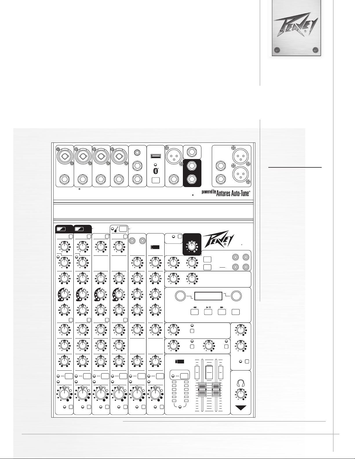
PV®10AT • PV®10BT
Compact Mixer
1/4”-Hi-Z CH.4 Only
DIRECT OUT
1
DIRECT OUT
DIRECT OUT DIRECT OUT
2345/6
PV 10AT
min max
GAIN
min max
COMP
0
+
-
min max
HIGH
0
+
-
low high
MID-MORPH
0
+
-
min max
LOW
Auto-TUNE
HI PASS
min max
GAIN
0
+
-
min max
HIGH
0
+
-
low high
MID-MORPH
0
+
-
min max
LOW
HI PASS
min max
GAIN
-
min max
HIGH
-
low high
MID-MORPH
-
min max
LOW
AT AT
HI PASS
comp
EQ BYPASS EQ BYPASS EQ BYPASS EQ BYPASS
min max
GAIN
min max
COMP
0
+
-
min max
HIGH
0
+
-
low high
MID-MORPH
0
+
-
min max
LOW
HI PASS
comp
USB A
3.5mm STEREO
5
L
6R
AUX SEND
PAIRING
7/8
10 INPUT STEREO MIXER
WITH DIGITAL EFFECTS, MEDIA PLAYBACK AND BLUETOOTH
ELECTRIC GUITAR PRE-SHAPE
RL
USB A
min max
GAIN
0
0
0
0
+
+
+
-
min max
HIGH
0
-
min max
MID
0
-
min max
LOW
+
+
+
USB B
Bluetooth
min max
GAIN
0
+
-
min max
HIGH
0
+
-
min max
MID
0
+
-
min max
LOW
PHANTOM POWER
48V
min max
LEVEL A/B
min max
RECORD LEVEL
Press to
Select
FS
L
STEREO IN
R
9/10
9/10
min max
STEREO IN LEVEL
min max
REC LEVEL
min max
TO CONTROL ROOM
EFFECts
media
MAIN
OUTPUTS
9
10
CONTROL ROOM
USB MEDIA PLAYBACK
DIGITAL EFFECT/MEDIA PLAYBACK
SOLO/MAIN
A/B SELECT
B/REC
REC
L
R
A
B/
EFX SELECTMEDIA SELECT
PV 10
RL
USB
Press to
Select
or edit
AutoTUNE
L
R
Operating
Manual
min max
min max
left right
CLIP
SIGNAL
min max
SOLO
min max
AUX
min max
EFX
c
RL
left right
PAN
CLIP
SIGNAL
1 2 3 4 5/6 7/8
min max
LEVEL
SOLO SOLO SOLO SOLO SOLO
1
AUX
EFX
PAN
LEVEL
c
RL
CLIP
SIGNAL
min max
2
min max
AUX
min max
EFX
c
RL
left right
PAN
LEVEL
CLIP
SIGNAL
min max
3
min max
AUX
min max
EFX
c
RL
left right
PAN
LEVEL
ANALOG
MEDIA CHANNEL
CLIP
SIGNAL
min max
4
min max
left right
AUX
BAL
LEVEL
c
5/6
RL
MUTEMUTEMUTEMUTEMUTE
min max
AUX
DIGITAL
MEDIA CHANNEL
c
RL
left right
BAL
CLIP
SIGNAL
min max
LEVEL
7/8
L
MASTER
SOLO
SOLO
min max
L
MONO
(SUM)
MIC MUTEMUTE
R
SOLO
min max
min max
RETURN TO MAIN RETURN TO AUX
STEREO
MAIN L+R
min max
AUX
HIGH
EFX
MUTE
min max
EFX
R
LOW
ENABLE
KOSMOS-C
HEADPHONE/
SOLO/MAIN
min max
LEVEL
SOLO/MAIN
www.peavey.com
Page 2

FCC/ICES Compliancy Statement
This device complies with Part 15 of the FCC rules and Industry Canada license-exempt RSS Standard(s). Operation
is subject to the following two conditions: (1) this device may not cause harmful interference, and (2) this device
must accept any interference received, that may cause undesired operation.
Le présent appareil est conforme aux CNR d’lndustrie Canada applicables aux appareils radio exempts de licence.
L’exploitation est autorisée aux deux conditions suivantes: (1) I’appareil ne doit pas produire de brouillage, et (2)
I’utilisateur de I’appareil doit accepter tout brouillage radioélectrique subi, même si le brouillage est susceptible
d’en compromettre le fonctionnement.
Warning: Changes or modifications to the equipment not approved by Peavey Electronics Corp. can void the user’s
authority to use the equipment.
Note – This equipment has been tested and found to comply with the limits for a Class B digital device, pursuant to
Part 15 of the FCC Rules. These limits are designed to provide reasonable protection against harmful interference
in a residential installation. This equipment generates, uses, and can radiate radio frequency energy and, if not
installed and used in accordance with the instructions, may cause harmful interference to radio communications.
However, there is no guarantee that interference will not occur in a particular installation. If this equipment does
cause harmful interference to radio or television reception, which can be determined by turning the equipment off
and on, the user is encouraged to try and correct the interference by one or more of the following measures.
• Reorient or relocate the receiving antenna.
• Increase the separation between the equipment and receiver.
• Connect the equipment into an outlet on a circuit different from that to which the receiver is con-
nected.
• Consult the dealer or an experienced radio/TV technician for help.
Caution
The equipment complies with FCC radiation exposure limits set forth for an uncontrolled environment.
Features and specifications are subject to change without notice.
Peavey Electronics Corporation • 711 A Street • Meridian, MS 39301
(601) 483-5365 • FAX (601) 486-1278 • www.peavey.com
© 2015 EX000030
Page 3

ENGLISH
PV®10AT and PV®10BT
Compact Mixers
Congratulations on purchasing the Peavey PV®10AT or PV®10BT Compact Mixer. e PV®10AT and PV®10BT are studio-quality mixing consoles designed to meet diverse needs while occupying a small space. ese are the perfect consoles for small venue performances or home recording environments. PV series mixers feature built-in DSP eects that are useful in real-world recording and sound reinforcement, while parameter
controls allow you to tailor each eect to meet your needs.
e PV 10 BT includes 4 channels of reference-quality mic preamps, 4 direct outputs for recording, a stereo channel, media channel with Bluetooth wireless input, high quality digital eects with LCD display, streaming USB out, MP3 playback via USB A input, Peavey's exclusive Kosmos
audio enhancement, 48 volt phantom power, dual selectable control room outputs, 2 channels of compression, one channel of on board selectable
guitar preamp, 3-band EQ per channel with bypass, channel mute buttons, aux send, signal clip indicators, and a stereo master LED meter bridge.
is amazingly versatile mixer is at home both in the studio as well as live applications. Its modern features such as Bluetooth allow seamless
connection to almost any "smart" device. 4 direct outs allow easy connection to most DAW interfaces for recording; in addition, the PV 10 BT can
stream audio directly to a PC. MP3 playback is also available, just plug a ash drive with MP3 les on it into the USB A port and use the LCD to
select and playback music. e PV series Solo feature allows the user to listen to individual channels via headphone or control room outputs and
the EQ bypass allows the user to compare the EQ'd signal to the original signal with the push of a button. 2 Channels of compression keep signals
with dicult levels under control, and Peavey's exclusive guitar-shape adjusts the EQ and preamp specically for guitar. Hi pass lters on every
channel remove unwanted rumble and noise, and balanced AUX and Master outputs ensure a clean noise free signal to your powered speakers or
power amplier. e all new PV series non-powered mixers represent the pinnacle of performance and value. Combine Peavey's legendary reliability and our 5 year warranty and you can be assure of years of quality reliable service, we guarantee it.
In addition to all of these features, the PV10AT features 2 channels of Antares® world-famous Autotune®, which can be set to subtly tighten up
vocal harmonies, or it can be set for robotic vocal eects heard in today's popular music. Peavey's exclusive custom key feature makes it a snap to
auto-tune to any scale you can think of, in a live performance. It is so easy and fast, you can set it up between songs, right in the middle of a set.
Please read this guide carefully to ensure your personal safety as well as the safety of your equipment.
FEATURES:
• 4 Combination 1/4" and XLR low noise mic preamps
• Stereo 1/4", RCA or 3.5mm input channel
• Bluetooth wireless connectivity
• 3-band EQ on all channels
• 4 Channels of Peavey's Exclusive Mid-Morph
• 150 Hz low-cut switch on all mic inputs
• LED clip and signal present indication
• Individual channel mutes
• EQ Bypass per mic channel
• On board studio quality digital eects with individual channel control
• Eects and playback LCD display
• One pre-fader AUX send
• Precision 60 mm faders on master
• Dual selectable control room outputs / Record out with independent level
• Global 48V phantom power
• Main stereo outputs with balanced 1/4" and XLR connectors
• Rugged console design
Installation Note:
is unit must have the following clearances from any combustible surface: top: 8", sides: 12", back: 12"
• 2 channels of built-in compression
• Stereo pan control per channel
• On-board USB-A MP3 playback
• 4 Channels of direct out
• Kosmos -C bass and treble enhancement
• Channel 9/10 stereo return/input
• Individual Solo function
• Stereo USB-B streaming audio in and out
• High quality master LED meter bridge
• Master mic mute
• Studio quality headphone output
• Peavey's exclusive on-board 1 Meg guitar input
• Antares Auto-Tune with Peavey's exclusive Custom Key
feature
Page 4
PV10AT Front Panel (channels 1 and 2)
3.5mm STEREO
MAIN
OUTPUTS
STEREO IN
FS
AUX SEND
1
2345/6
7/8
USB A
DIRECT OUT
5
6R
L
R
L
10
9
R
L
R
L
DIRECT OUT DIRECT OUT
PAIRING
9/10
1/4”-Hi-Z CH.4 Only
LEVEL
3.5mm STEREO
MAIN
OUTPUTS
STEREO IN
FS
AUX SEND
MAIN L+R
1
1
2345/6
7/8
DIRECT OUT
RL
L
L
R
R
PHANTOM POWER
48V
USB A
SOLO/MAIN
CONTROL ROOM
SOLO/MAIN
USB
min max
HEADPHONE/
SOLO/MAIN
DIRECT OUT
SOLO
SOLO SOLO SO LO SOLO SO LO
5
6R
L
R
L
10
9
R
L
R
L
Press to
Select
Press to
Select
or edit
EFX SELECTMEDIA SELECT
DIGITAL EFFECT/MEDIA PLAYBACK
USB MEDIA PLAYBACK
EFFECts
media
min max
min max
DIRECT OUT DIRECT OUT
MIC MUTEMUTE
MASTER
min max
RETURN TO MAIN RETURN TO AUX
DIGITAL
MEDIA CHANNEL
LEVEL A/B
min max
REC LEVEL
min max
RECORD LEVEL
min max
TO CONTROL ROOM
min max
ANALOG
MEDIA CHANNEL
RL
EFX
AUX
STEREO IN LEVEL
min max
ENABLE
A/B SELECT
B/REC
KOSMOS-C
min max
min max
HIGH
LOW
USB A
USB B
Bluetooth
MONO
(SUM)
STEREO
A
B/
REC
10 INPUT STEREO MIXER
WITH DIGITAL EFFECTS, MEDIA PLAYBACK AND BLUETOOTH
EQ BYPASS EQ BYPASS EQ BYPASS
PAIRING
LEVEL
min max
HIGH
LOW
0
-
+
min max
0
-
+
min max
PAN
c
RL
left right
EFX
min max
AUX
min max
COMP
min max
GAIN
2
min max
comp
HI PASS
MID-MORPH
0
low high
-
+
LEVEL
min max
HIGH
LOW
0
-
+
min max
0
-
+
min max
PAN
c
RL
left right
EFX
min max
AUX
min max
GAIN
3
min max
HI PASS
MID-MORPH
0
low high
-
+
LEVEL
min max
HIGH
LOW
0
-
+
min max
0
-
+
min max
PAN
c
RL
left right
EFX
min max
AUX
min max
GAIN
4
min max
HI PASS
MID-MORPH
0
low high
-
+
LEVEL
min max
HIGH
LOW
0
-
+
min max
0
-
+
min max
BAL
c
RL
left right
AUX
min max
GAIN
5/6
min max
MID
LEVEL
min max
HIGH
LOW
0
-
+
min max
0
-
+
min max
0
-
+
min max
0
-
+
min max
BAL
c
RL
left right
AUX
min max
GAIN
7/8
1 2 3 4 5/6 7/8
min max
MID
PV 10AT
PV 10
ELECTRIC GUITAR PRE-SHAPE
9/10
9/10
EFX
MUTE
SOLO
SOLO
1/4”-Hi-Z CH.4 Only
SIGNAL
CLIP
SIGNAL
CLIP
SIGNAL
CLIP
SIGNAL
CLIP
SIGNAL
CLIP
MUTEMUTEMUTEMUTE
Auto-
TUNE
Auto-TUNE
AT
1
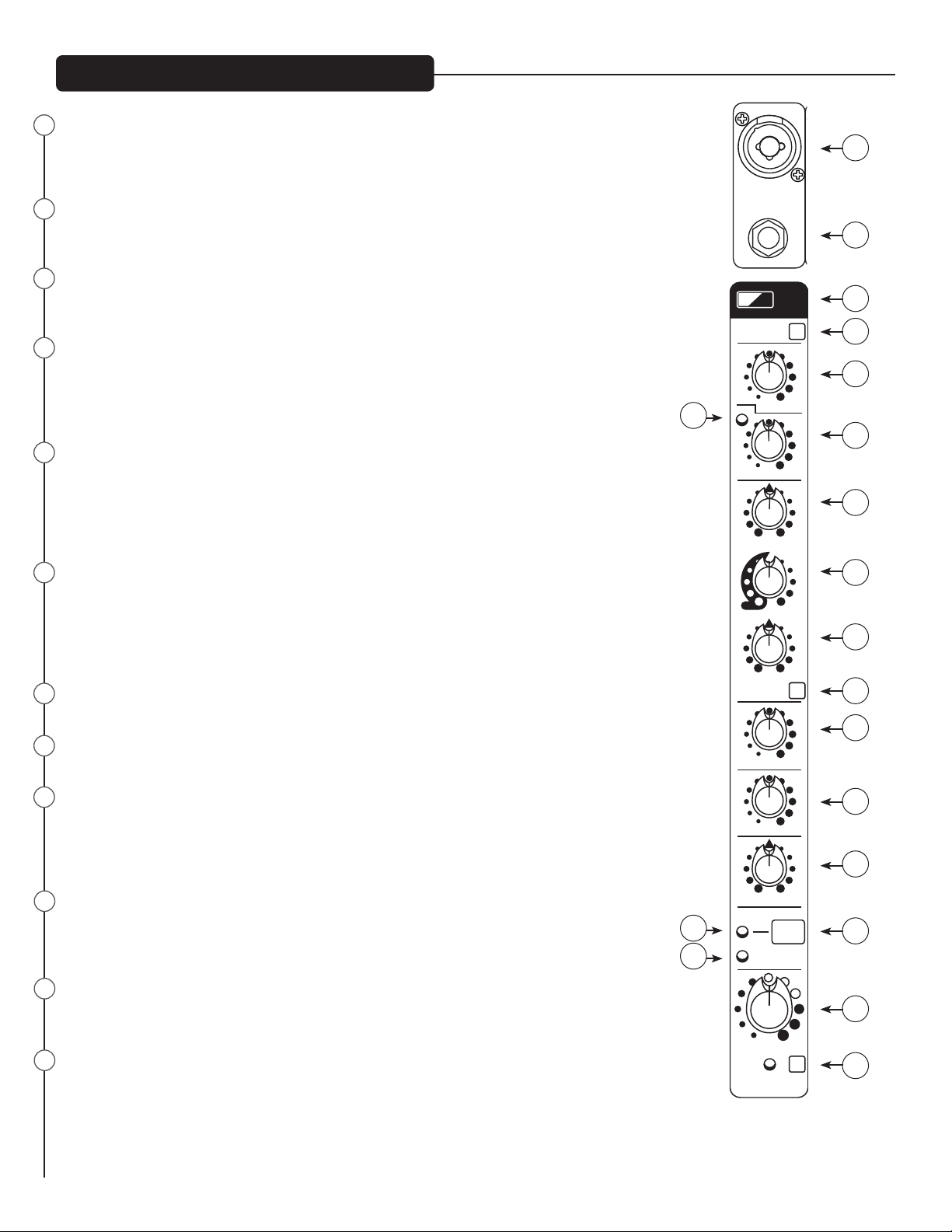
MIC/LINE INPUT (CH.1-8)
is combination input jack accepts a ¼” or XLR balanced plug. e XLR balanced input is optimized
for a microphone or other low impedance source. e ¼” input is a TRS balanced type, and also accepts
ordinary TS guitar cables.
2
DIRECT OUT
is impedance-balanced TRS output signal is taken aer the mic preamp, hi pass lter, and compressor,
but before the EQ stage.
3
AUTO-TUNE ACTIVATION BUTTON AND LED (PV10AT only)
Pressing this button activates the PV10AT's onboard AUTO-TUNE feature. e button illuminates when
in AUTO-TUNE mode (SEE Eects Select {50} and the following page).
4
GAIN
e Input Gain control is used to establish proper gain structure in the channel. For best results, use the
Solo system (19) to monitor the channel while you set the gain. e goal is maximum gain without distortion. Both the main LED meters (during Solo) and the channel’s Signal/Clip indicator (16,17) can be used
for adjusting gain. If the clip LED (16) comes on and remains lit, try reducing the gain.
5
150 Hz HI PASS FILTER
e hi pass lter has a corner frequency of 150 Hz. When engaged‚ it can improve clarity by removing
low frequencies that make a mix sound muddy. is feature is especially useful when playing outside on a
windy day or on a hollow-sounding‚ noisy stage. ese kinds of ambient noises can rob your sound system
of power. Engaging this switch will remove those frequencies from the system and restore power where
needed.
6
COMPRESSION CONTROL (Channels 1 and 2 only)
Adjusting this knob clockwise lowers the threshold of the compressor, thereby increasing the amount of
compression. e compressor ratio is in the 4:1 range, varying with signal levels and the amount of compression. is is useful for controlling peak levels from live sources, and has been designed to subtly tame
the levels of live vocals without noticeable artifacts. e compressor is aer the gain control (5) and the hi
pass lter (4), but before the direct out (2), so it can be patched to external equipment.
7
Compressor LED
is LED illuminates when the compressor is actively compressing a signal.
8
Hi EQ
is active tone control (shelving type: ±15 dB) varies the level of the high frequency range.
9
MID-MORPH EQ (CH. 1-7)
Where most mid-range controls work at just one frequency, the Mid-Morph works at two. When turned
counterclockwise, it cuts at 250Hz to reduce frequencies that muddy the sound. When turned clockwise,
it boosts at 4kHz to add intelligibility to vocals. Either way, improved vocal or instrument denition can
be achieved.
10
Low EQ
is active tone control (shelving type: ±15 dB) varies the level of the low frequency range. Caution: Excessive low frequency boost causes greater power consumption and increases the possibility of speaker
damage.
11
EQ BYPASS
Engaging this button bypasses the equalization of the channel, allowing you to easily hear the eect of
the EQ settings.
12
AUX SEND
is control adjusts the level of the channel signal sent to the Aux output. e signal is taken before the
channel level (18) but aer the channel EQ, meaning that changes to the EQ settings will aect the aux
mix, but changes to the channel level control won't. Typical use for the Aux bus is to feed stage monitors,
when used in a live performance, or to feed headphone ampliers in a recording situation.
7
DIRECT OUT
HI PASS
min max
comp
GAIN
min max
COMP
16
17
-
min max
HIGH
-
low high
MID-MORPH
-
min max
LOW
EQ BYPASS
min max
min max
left right
CLIP
SIGNAL
min max
LEVEL
SOLO
AT
0
+
0
+
0
+
AUX
EFX
c
RL
PAN
MUTE
1
2
3
4
5
6
8
9
10
11
12
13
14
15
18
19
Page 5
PV10AT Front Panel (channels 1 and 2)
3.5mm STEREO
MAIN
OUTPUTS
STEREO IN
FS
AUX SEND
7/8
RL
PHANTOM POWER
48V
USB A
CONTROL ROOM
SOLO/MAIN
5
6R
L
R
L
10
9
R
L
R
L
RL
STEREO IN LEVEL
min max
USB A
USB B
Bluetooth
10 INPUT STEREO MIXER
WITH DIGITAL EFFECTS, MEDIA PLAYBACK AND BLUETOOTH
PAIRING
GAIN
PV 10
9/10
9/10
1/4”-Hi-Z CH.4 Only
POWER
3.5mm STEREO
MAIN
OUTPUTS
STEREO IN
FS
AUX SEND
7/8
USB A
5
6R
L
R
L
10
9
R
L
R
L
PAIRING
9/10
13
EFX SEND
is control adjusts the level of the channel signal added to the eects mix. e signal is sent to the internal eects processor. Turning the knob to
the le (min) will turn o eects on the associated channel, while turning the knob to the right will increase the amount of the selected eect. e
eects send signal is taken aer the channel level (18) so that adjustments made to the fader will also aect the send level.
14
PAN CONTROL
is knob controls the placement of the signal in the stereo eld. When rotated completely counterclockwise‚ the signal is present only on the le
channel; when rotated completely clockwise‚ only in the right channel. is control functions as a balance control to adjust the relative level of the
le and right signals on stereo channels 5/6 and 7/8. (Note 1/4" inputs on ch 5-6 and 9-10 are mono unless both are connected, then they switch
to stereo)
15
MUTE SWITCH
Pressing this switch will silence the channel signal going to the main mix, aux send, and eects. e mute switch will not aect the signal sent to
the solo system.
16
CLIP/MUTE LED
is LED normally indicates that the channel signal level is near clipping (distortion), but it also lights when mute is engaged. e clip indicator
circuit monitors the signal aer the gain control, aer the EQ, and aer the main level; because clipping can be caused by high settings of any
of these controls. It illuminates at +15 dBu with a static signal (test tone), and corresponds to audible clipping with a highly dynamic signal (i.e.
piano). When lit, it warns that the gain or EQ boost should be reduced. When it lights, roughly 5 dB of headroom remains. An optimized setting
of input gain + EQ will result in this LED ashing briey on the loudest peaks.
17
SIGNAL LED
e signal LED lights when the channel level reaches approximately -20 dBu. is not only indicates which channels are active, but also serves as
a mini level meter. Because its illumination varies with the signal source, it is useful in identifying which channel is carrying a particular source.
18
CHANNEL LEVEL CONTROL
is is the channel's output control, which sets the signal level sent to the le and right mix and the eects send control. e gain is 0 dB (unity gain) when set to the detent at mid-rotation (12:00). 10 dB of boost is available at the max gain setting. Normal operation is to start with
this knob at the detent, and set the input gain and EQ with the source playing such that normal levels are seen at the signal /clip LED's and the
main meter array. As additional sources are added, it is normal to turn this knob down slightly to prevent overdriving the main mix bus.
19
SOLO SWITCH AND LED
When the Solo switch is engaged, the yellow LED lights, as does the yellow Solo LED under the main L/R meter array in the master section, indicating that the Solo system is now active. e Solo system is a separate mix bus that routes the soloed channel(s) at unity gain to
the level meters for precise input level setting, and to the control room monitor and headphone outputs for critical listening to the selected
source(s). When the Solo system is active, the complete mix will no longer be heard through the control room or headphones; only the soloed
channel(s).
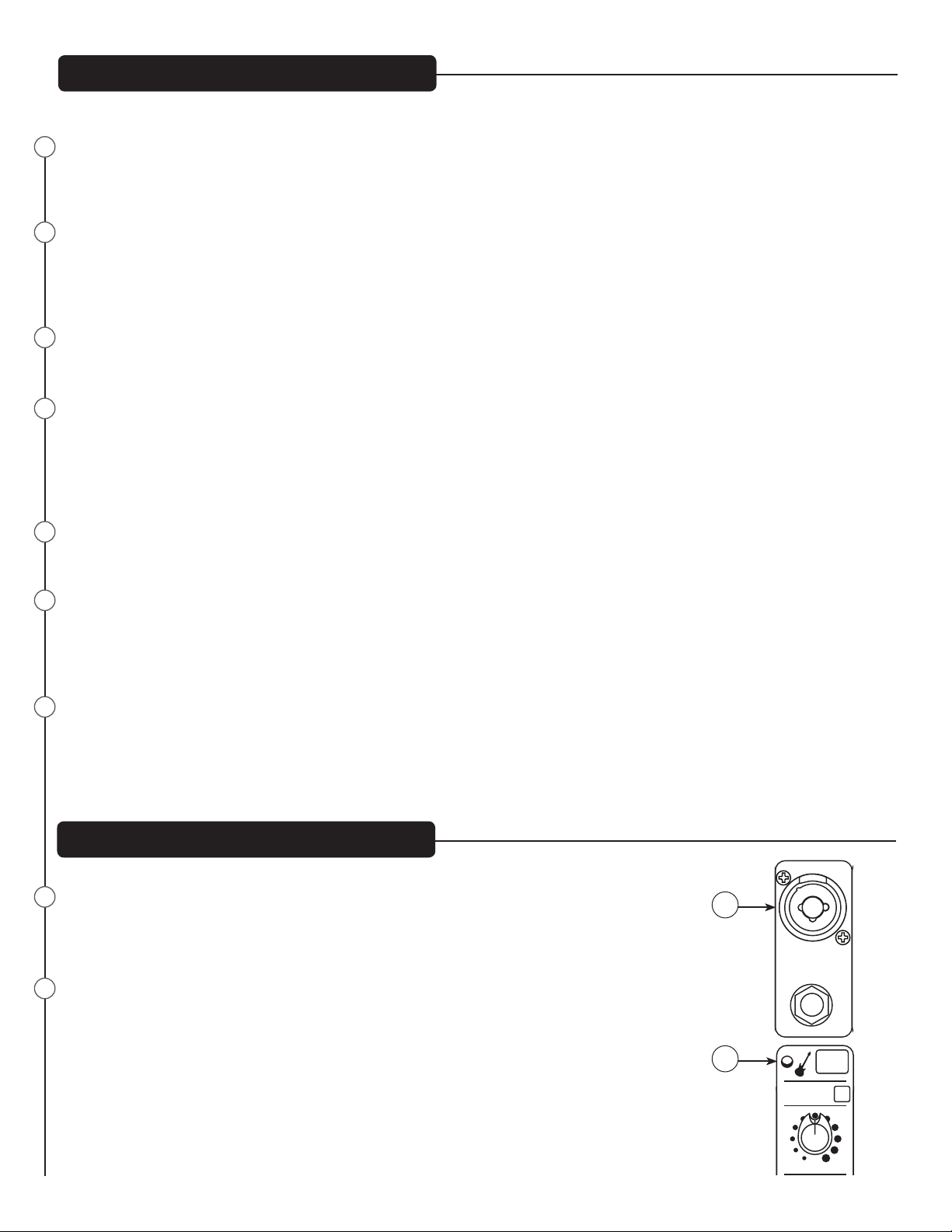
PV10AT Front Panel (channel 4)
20
MIC/LINE INPUT (CHANNEL 4 ONLY)
is input is the same as channels 1-3 unless Guitar Shape is pressed. When ELECTRIC GUITAR
PRE-SHAPE is on, the 1/4" input changes to a high impedance (1 MegΩ), like a 12AX7 vacuum tube
guitar amplier input.
21
Electric Guitar Pre-Shape
Engaging this button optimizes the on board equalization for electric guitar.
20
1/4”-Hi-Z CH.4 Only
DIRECT OUT
21
HI PASS
min max
Page 6
LEVEL
3.5mm STEREO
MAIN
OUTPUTS
STEREO IN
FS
AUX SEND
MAIN L+R
7/8
RL
L
L
R
R
PHANTOM POWER
48V
USB A
SOLO/MAIN
CONTROL ROOM
SOLO/MAIN
USB
min max
HEADPHONE/
SOLO/MAIN
SOLO
5
6R
L
R
L
10
9
R
L
R
L
Press to
Select
Press to
Select
or edit
EFX SELECTMEDIA SELECT
DIGITAL EFFECT/MEDIA PLAYBACK
USB MEDIA PLAYBACK
EFFECts
media
min max
min max
MIC MUTE
MASTER
min max
RETURN TO MAIN RETURN TO AUX
LEVEL A/B
min max
REC LEVEL
min max
RECORD LEVEL
min max
TO CONTROL ROOM
min max
EFX
AUX
STEREO IN LEVEL
min max
ENABLE
A/B SELECT
B/REC
KOSMOS-C
min max
min max
HIGH
LOW
MONO
(SUM)
STEREO
A
B/
REC
PAIRING
PV 10
9/10
9/10
EFX
MUTE
SOLO
SOLO
POWER
MAIN
OUTPUTS
STEREO IN
FS
AUX SEND
R
L
10
9
R
L
R
L
9/10
PV10AT/PV10BT Front Panel (channels 5, 6, 7 and 8)
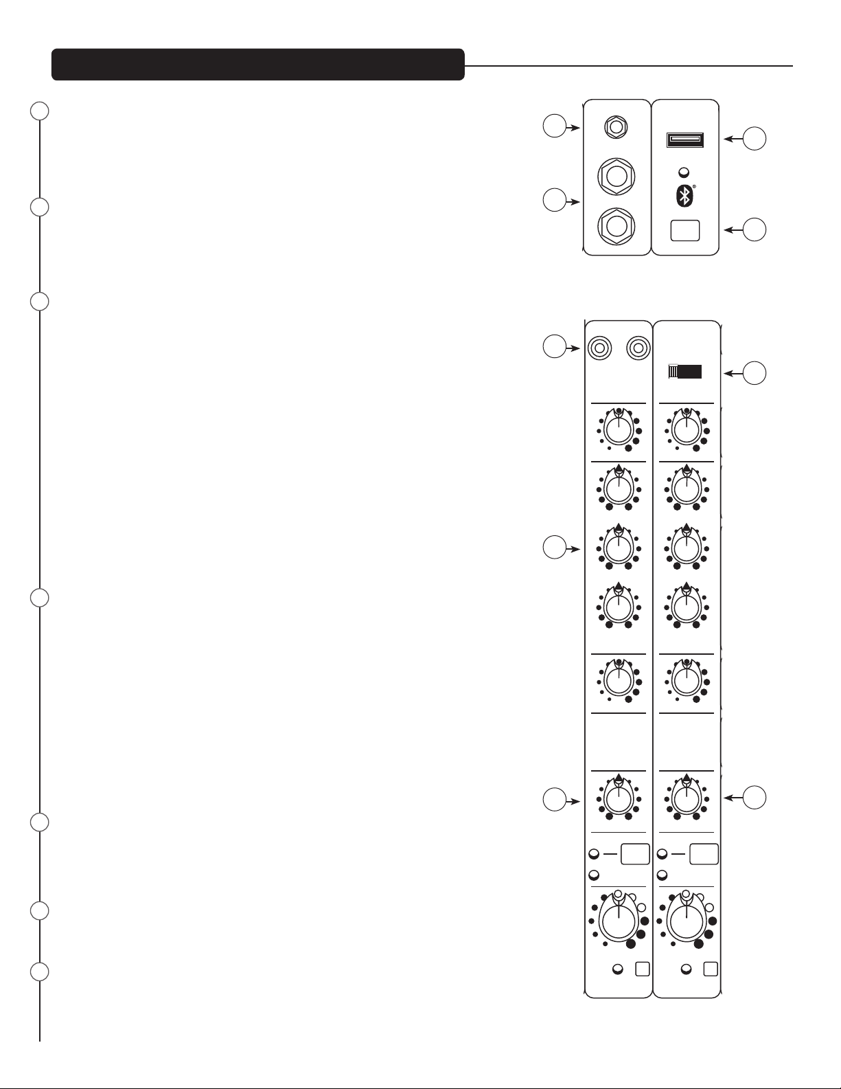
22
3.5mm STEREO INPUT
e 3.5mm input to channel 5/6 accepts a stereo input from the output of an MP3 player,
CD player, tape deck or other similar device. is input is optimized for portable handheld devices and therefore has very high sensitivity.
23
STEREO INPUTS
Channels 5 and 6 also feature 1/4" inputs. If only one jack is used, it behaves as a mono
source with a pan control. When both jacks are connected, these connections serve as a
stereo source with a balance control; 5 is Le and 6 is Right.
24
USB MEDIA JACK
A-type USB connector that a removable data storage device can be connected to playback
music
USB PLAYBACK:
First, slide the input selection switch (27) to the USB A position. e bottom of the LCD
display will say “Insert USB drive”. Insert your USB drive into the USB Media Jack (24)
at the top of channel 7/8. e Media Player will now enter "Folder Navigation Mode". In
this mode, you can scroll through a list of all folders on the USB drive. Once you select
a folder, the Media Player will enter "Song Navigation Mode" which allows you to scroll
through a list of all songs contained in the selected folder. If there are no songs in the
selected folder, the LCD will display "No Songs". To return to Folder Navigation Mode, scroll
to the very beginning of the list and select the <FOLDERS> option.
Once a song is nished playing, the Media Player will automatically start playing the next
song. Once the Media Player reaches the last song, it will automatically loop back to the
beginning of the list.
25
BLUETOOTH PAIRING BUTTON AND LED
e Bluetooth Pairing Button is used to turn on/o the Bluetooth. Once turned on, the
Bluetooth will automatically enter pairing mode. You can pair any Bluetooth-enabled
device with the mixer using the PIN 7878. e blue “Bluetooth Active LED” indicates the
status of the Bluetooth connection. If the LED is o, the Bluetooth module is powered
o. If the LED is slowly ashing, the PV mixer is not paired with any device, but is available for connection. When the LED is lit solid, the source device is properly paired to the
mixer and ready to play. To clear the paired device memory, make sure Bluetooth is on
and press and hold the Bluetooth Pairing Button for 5 seconds. e PV mixer will ask if
you would like to clear the Bluetooth memory. Select "Y" using the Media Select knob
to clear the memory. e PV mixer will go through the process of clearing the memory,
which should take approximately 15 seconds.
26
RCA MEDIA INPUTS
e RCA inputs to channel 5/6 accept a stereo source such as an MP3 player, CD player,
tape deck or other similar device. is input is optimized for portable handheld devices
and therefore has very high sensitivity.
27
DIGITAL SOURCE SELECTOR
is switch selects between USB A (24), USB B (68), and the internal Bluetooth receiver.
28
MID CONTROL
Stereo channels' midrange is +/-20 dB @ 440Hz ; the HIGH (8) and LOW (10) controls are
described above.
22
3.5mm STEREO
L
USB A
24
5
23
PAIRING
5/6
6R
7/8
25
RL
26
USB B
27
USB A
Bluetooth
min max
GAIN
0
-
min max
HIGH
0
min max
GAIN
0
+
+
-
min max
HIGH
0
28
29
+
-
min max
MID
0
+
-
min max
LOW
min max
AUX
ANALOG
MEDIA CHANNEL
c
RL
left right
BAL
MUTE
CLIP
SIGNAL
+
-
min max
MID
0
+
-
min max
LOW
min max
AUX
DIGITAL
MEDIA CHANNEL
c
RL
left right
BAL
MUTE
CLIP
SIGNAL
30
5/6 7/8
min max
LEVEL
SOLO SOLO
5/6
min max
LEVEL
7/8
Page 7

9/10
PV10AT/PV10BT Front Panel (channel 4)
32
ANALOG BALANCE CONTROL
29
31
AUX SEND
FS
L
STEREO IN
R
33
10
MAIN
OUTPUTS
9
L
R
34 35
L
R
Controls the balance between the analog channels 5/6.
30
DIGITAL BALANCE CONTROL
Controls the balance between the digital channels 7/8.
31
AUX SEND XLR and 1/4" OUT
Ground compensated balanced output fed by the AUX SEND master level (52). e XLR is internally in parallel with the TRS. You will
get better hum and noise rejection by using balanced interconnects (either XLR or TRS), but unbalanced Tip Sleeve (TS) cables will
also work.
32
FOOTSWITCH
is TRS jack is designed for use with Peavey's 2 Button Special Use Momentary Footswitch, Item # 03014070. e tip of this TRS jack,
switch 1, remotely actuates the EFX Mute switch. e ring of the TRS jack, switch 2, remotely turns o the Auto-Tune on AT models.
is makes the use of Auto-Tune inconspicuous; by using the footswitch, your between-songs spoken banter won't be Auto-Tuned.
33
1/4" STEREO INPUTS
Channel 9 and 10 are a stereo pair of 1/4" jacks that can be used for an aux input, or eects return from an external processor.
If only one jack is used, it behaves as a mono source. Once both jacks are connected, it behaves as a stereo source; 9 is Le and 10 is
Right.
34
1/4" STEREO OUTPUTS
Ground compensated balanced output fed by the master L and R Faders (60). e TRS jacks are internally in parallel with the XLR's.
You will get better hum and noise rejection by using balanced interconnects (either XLR or TRS), but unbalanced Tip Sleeve (TS)
cables will also work.
35
XLR STEREO OUTPUTS
Ground compensated balanced output fed by the master L and R Faders (60). e XLR jacks are internally in parallel with the TRS's.
You will get better hum and noise rejection by using balanced interconnects (either XLR or TRS).
Page 8

MAIN
OUTPUTS
STEREO IN
FS
AUX SEND
R
L
10
9
R
L
R
L
LEVEL A/B
REC LEVEL
9/10
PV10AT Front Panel
36
PHANTOM POWER
48V
37
9/10
PV 10
RL
43
4441
36
PHANTOM POWER
min max
STEREO IN LEVEL
min max
39 40 42
min max
CONTROL ROOM
SOLO/MAIN
A/B SELECT
B/REC
REC
A
B/
is Switch applies +48 VDC voltage to the input XLR connectors to power microphones requiring phantom power.
If phantom power is used, do not connect unbalanced dynamic microphones or other devices to the XLR
inputs that cannot handle this Voltage.
37
STEREO IN LEVEL 9/10
Controls the level of input jacks 9 and 10. If only one jack is connected, it is sent to both L and R. If both jacks are connected, 9 is L and 10 is R.
e Aux output could be fed to an external eects processor, and these jacks could be used as the eects return. Or a second mixer could be
daisy-chained in here.
39
LEVEL A/B
Controls the level of both A and B control room outputs. e active output is selected with A/B SELECT switch (41), when B/REC switch (42)
is up. When B/REC switch is down, only output A is controlled.
40
REC LEVEL
When B/REC switch is down, controls the level at the B/REC outputs. Note: When B/REC switch is up, this control is inactive.
41
A/B SELECT
When this switch is up, output A is on and output B is o. When this switch is down, output B is on and output A is o. Use this switch to
evaluate a mix on 2 dierent pairs of monitors, such as near eld and far eld monitors. By setting the level controls on both monitoring systems the same, a rapid A/B comparison can be made. Overall monitor level is controlled by LEVEL A/B. NOTE: When the B/REC switch (42)is
down, this switch is disabled , and the A output remains on at all times, fed by LEVEL A/B (39).
42
B/REC SWITCH
Determines the function of the B/REC output. When up, B/REC jack functions as monitor B output, selected by A/B select and controlled by
LEVEL A/B. When down, B/REC jack is an independent record output, with level controlled by REC LEVEL.
43
CONTROL ROOM MONITOR OUTPUT A
Connect powered monitors, or an amplier feeding monitor speakers here. Set the volume controls on the monitors A and B to be equal
when the A/B switch is toggled. e signal sent to this output is normally the Le/Right mix. e USB "To Control Room" pot (47) feeds the
USB return signal to these Monitor Outputs for use in a DAW recording setup. When the Solo LED is lit (62), only the soloed source(s) will
be heard. NOTE: When the B/REC switch is down, the A/B SELECT switch becomes disabled, and this output is output is controlled by the LEVEL
A/B control.
Page 9

PV10AT Front Panel
MAIN
OUTPUTS
STEREO IN
FS
AUX SEND
RL
PHANTOM POWER
48V
CONTROL ROOM
SOLO/MAIN
R
L
10
9
R
L
R
L
LEVEL A/B
min max
REC LEVEL
min max
STEREO IN LEVEL
min max
A/B SELECT
B/REC
A
B/
REC
PV 10
9/10
9/10
44
CONTROL ROOM MONITOR OUTPUT B / RECORD OUT
is pair of outputs can either serve as your "B" Record Monitor Output; or, with the B/REC switch (42) down, as an independently controlled
Record Output. NOTE: When the B/REC switch is down, the A/B SELECT switch becomes disabled, and this output is output is controlled by the
B/REC control.
USB RECORD LEVEL KNOB
45
Controls the level of signal sent to the USB B connector on the back of the mixer. e recommended setting is near 12:00, but a wide range is
available to accommodate varying levels and sensitivites.
46
CONTROL ROOM LEVEL
Controls the level of signal returning from the USB B connector on the back of the mixer. e signal is routed to the control room and headphone outputs, for multitrack recordings on a DAW. e recommended setting is near 12:00.
48
45
min max
RECORD LEVEL
Press to
Select
46 47
min max
TO CONTROL ROOM
EFFECts
media
USB MEDIA PLAYBACK
USB
Press to
Select
or edit
EFX SELECTMEDIA SELECT
AutoTUNE
49
51
DIGITAL EFFECT/MEDIA PLAYBACK
50
47
MEDIA AND EFFECTS LCD DISPLAY
e top row of this LCD displays the currently selected Eect and the bottom row displays the statusof the MP3 Player, which can be used for
navigating the folders on the USB drive or displaying the current song playing. e bottom line will also briey display the Bluetooth status
during power on, power o, and memory clearing.
48
MEDIA SELECT
Once a USB device is connected in channel 8, you can use the “Media Select” encoder to navigate through the folders/songs on the drive.
Once the desired le is displayed on the screen, press the Media Select knob to cue that le. Use the controls on the mixer for play, pause,
forward and reverse.
49
EFX SELECT KNOB
See detailed description on the following page.
MEDIA PLAYBACK CONTROLS
50
ese controls allow you to play, pause and scroll though digital media via USB jack.
51
AUTO-TUNE MODE BUTTON (PV10AT ONLY)
Pressing this switch changes the top line of the LCD between Auto-Tune Edit Mode and EFX Edit Mode. is funtion is not available in
the PV10BT.
Page 10

PV10AT Front Panel
EFX Select Knob:
EFX Mode:
In EFX Edit Mode (see Auto-Tune Switch), the EFX Select knob is used to navigate through the EFX presets. Turning the knob changes the
EFX preset in the display. e new selection will be blinking in the display; push the EFX Select knob to choose the new eect. Once the effect has been selected, you can now edit the eect. To do this, press the EFX Select knob and the display will change to the current parameter
setting of the preset. Turn the EFX Select knob to edit the parameter. Press the knob again to exit EFX preset edit mode. To restore the EFX
presets back to factory settings, press and hold the EFX Select knob for 5 seconds and select "Y" when prompted.
Auto-Tune Mode:
In Auto-Tune Edit Mode (see Auto-Tune Switch), the EFX Select knob is used to navigate through the Auto-Tune presets. Turning the knob
changes the Auto-Tune preset in the display. e new selection will be blinking in the display; push the EFX Select knob to choose the new
Auto-Tune preset.
Once the preset has been selected, you can edit the preset by pressing the EFX Select knob. e display will change to the current Key setting.
Turn the EFX Select knob to change the key and push the EFX Select knob when you have chosen the key you desire. e Key setting determines which notes are enabled in the Auto-Tune process. For example, in the key of CMaj, the notes C, D, E, F, G, A, and B are enabled, and all
other notes are disabled. To see which notes are enabled or disabled for each key, see the Key Table below.
Note:
If Custom Key is selected, the display will enter Custom Key Edit Mode. In this mode, you can create a custom Auto-Tune Key. Use
the EFX Select knob to select the Root (labeled "RT"). is will be the note o which the custom key is based. en use the
Media Select knob to move the cursor and use the EFX Select knob to activate or deactivate the 12 notes in the key. Once you have
nished editing the custom key, press the EFX Select knob to exit Custom Key Edit Mode. e mixer is capable of storing 9 dierent
custom keys, one for each preset slot.
e scale degrees are numbered across the top, with half-steps indicated by a dash.
RT=Root or Key
RT
*
*indicates the root or key
is C
"+" indicates the note will be allowed.
"-" indicates the note will not be allowed.
By looking at the sequence of allowed and disallowed notes above, this is a whole tone scale. ere are only two of those, so you can have the
other one just by changing the root to C# or B.
*is screen cap shows an A blues scale. You don't have to edit the whole scale to change keys - just change the root.
Once you have selected the key and pressed the EFX Select knob, the display will change to the current Speed setting. Turn the EFX Select
knob to change the Speed setting. e Speed setting determines how quickly and aggressively the Auto-Tune will correct the pitch. e range
for this setting is 0 to 25, where 0 is the quickest and 25 is the slowest. Push the EFX Select knob when you are done editing the speed parameter.
Page 11

e display will now change to the current Detune setting. Turn the EFX Select knob to change the Detune setting. e Detune setting
determines how the Auto-Tune pitch correction is calibrated. When the Detune setting is 0 cents, this means the Auto-Tune is calibrated to
the standard A440, or where the note A4 equals 440 Hz. e range of the Detune setting is -64 to 63 cents, a width of 128 cents. e distance
between two notes, or semitones, is 100 cents, which means that the Auto-Tune can be detuned to t any possible environment.
Note:
Detuning the Auto-Tune can be very useful, especially when being used in conjunction with an instrument that is not easily tuned
on-the-y. For example, if a piano is accompanying Auto-Tuned vocals and the piano is slightly out of tune from the A440 stan
dard, simply change the Detune setting in the Auto-Tune setting. is is much easier and takes much less time than having some
one tune the entire piano! Also, although the Detune setting is changed in the Auto-Tune preset edit mode, this is a global param
eter. is means if you change the Detune setting and then later change the Auto-Tune preset, the Detune setting will not change.
Once you have selected the appropriate Detune setting, press the EFX Select knob to exit Auto-Tune preset edit mode. To restore all AutoTune presets back to factory settings, press and hold the EFX Select knob for 5 seconds and select "Y" when prompted.
Note:
Preset 9 is chromatic with speed set to 7. It is recommended for general purpose, safe, easy use of Autotune, without having to
adjust any settings. e slower speed setting does not produce a robotic eect on the voice, and all twelve semitones are allowed.
Just remember to use footswitch #2 to bypass Autotune between songs, otherwise your speaking will be Autotuned!
Auto-Tune Key Table
Auto-Tune Key Table
Key Display Note Number (n)=
Key 0 1 2 3 4 5 6 7 8 9 10 11
Chrom C C# D D# E F F# G G# A A# B
C Maj C D E F G A B
C Mnr C D D# F G G# A#
C#Maj C C# D# F F# G# A#
C#Mnr C# D# E F# G# A B
D Maj C# D E F# G A B
D Mnr C D E F G A A#
D#Maj C D D# F G G# A#
D#Mnr C# D# F F# G# A# B
E Maj C# D# E F# G# A B
E Mnr C D E F# G A B
F Maj C D E F G A A#
F Mnr C C# D# F G G# A#
F#Maj C# D# F F# G# A# B
F#Mnr C# D E F# G# A B
G Maj C D E F# G A B
G Mnr C D D# F G A A#
G#Maj C C# D# F G G# A#
G#Mnr C# D# E F# G# A# B
A Maj C# D E F# G# A B
A Mnr C D E F G A B
A#Maj C D D# F G A A#
A#Mnr C C# D# F F# G# A#
B Maj C# D# E F# G# A# B
B Mnr C# D E F# G A B
Page 12

LEVEL
MAIN
OUTPUTS
STEREO IN
FS
AUX SEND
RL
PHANTOM POWER
48V
SOLO/MAIN
CONTROL ROOM
SOLO/MAIN
USB
min max
HEADPHONE/
SOLO/MAIN
R
L
10
9
R
L
R
L
Press to
Select
Press to
Select
or edit
EFX SELECTMEDIA SELECT
DIGITAL EFFECT/MEDIA PLAYBACK
USB MEDIA PLAYBACK
EFFECts
media
LEVEL A/B
min max
REC LEVEL
min max
RECORD LEVEL
min max
TO CONTROL ROOM
min max
STEREO IN LEVEL
min max
ENABLE
A/B SELECT
B/REC
KOSMOS-C
min max
min max
HIGH
LOW
A
B/
REC
PV 10
9/10
9/10
POWER
PV10AT Front Panel
52 53 55
54
min max
MASTER
SOLO
AUX
56
58
59
SOLO
min max
RETURN TO MAIN RETURN TO AUX
MIC MUTE
MONO
(SUM)
STEREO
min max
L
EFX
MUTE
EFX
R
61
52
AUX MASTER CONTROL KNOB
Controls the overall level of the signal coming out of the Aux Output (31). is Auxiliary output is typically fed to a power amplier to drive
62
L
SOLO
MAIN L+R
R
57
60
stage monitors so singers can hear themselves amidst amplied instruments, or to a headphone amplier to give vocalists a monitor feed that
will not be picked up by microphones while recording.
53
AUX MASTER SOLO BUTTON AND LED
Allows you to listen to just the Auxiliary mix. e setting of the AUX MASTER knob determines the level you will hear when this button is
pressed.
54
EFX RETURN SOLO BUTTON AND LED
Allows you to listen to just the eects return. e setting of the Return to Main knob determines the level you will hear when this button is
pressed.
55
RETURN TO AUX CONTROL KNOB
is control determines the level of the internal digital eects processor being sent to the Aux output. One possible use is to put reverb in the
headphones of a vocalist, to give them a condence boost for recording, without putting any reverb on the actual recorded track. Or in a live
situation, the same can be done by feeding a delay or reverb to the monitors.
56
EFX RETURN TO MAIN
is control determines the level of the internal digital eects processor being sent to the main L and R outputs.
57
EFX MUTE BUTTON AND LED/CLIP LED
When depressed, the output of the internal digital eects is shut o. Muting the eects is an easy way to determine what a particular eect is
doing to your mix. LED remains lit when EFX MUTE is engaged. When EFX MUTE is not engaged, this LED functions as a clip indicator for
the internal digital eects. If the digital eects are clipping, reduce the level of the EFX SEND pots.
Page 13

PV10AT Front Panel
58
STEREO/MONO MODE SWITCH
In the mono position, the le and right buses are summed together aer the faders. In this position, the L fader controls the level of the L bus,
and the R fader controls the level of the R bus, allowing you to use the L and R buses as groups. For example, all vocals could be panned L and
all instruments panned R. en the L fader becomes the vocal master level and the R becomes the instruments master level.
59
MIC MUTE BUTTON AND LED
Depressing this button mutes all of the mic inputs channels (1-4) and the eects return. e media input channels are still "live". is allows
you to play break music, while muting all of the microphone inputs.
60
MAIN LEVEL FADERS
e Master Faders control the levels sent to the Main Le/Right outputs (34, 35). Best results are obtained when these controls are set near the
midpoint of the enclosed rectangle.
61
MAIN L+R METER ARRAY
Displays the level of the L and R outputs, or, when solo is active, displays the soloed channel(s). e top green LED corresponds to an output
level of +4dBu. e red LED is a clip warning indicator. e range of the meter is from -17 dBu to + 15 dBu.
62
MAIN SOLO LED
Lights when any solo button is pushed, to indicate that the solo system is active.
Page 14

RL
USB
R
L
Press to
Select
or edit
PV 10
POWER
PV10AT Front Panel
63
KOSMOS-C HIGH CONTROL
A very selective high frequency lter with a high Q. e eect varies with source material, so some experimentation is required for optimum results.
64
KOSMOS-C LOW CONTROL
is Kosmos-C Low enhancement works by creating harmonics of signals in the bottom ocave, where
speakers are usually ineective. e harmonics are more easily reproduced, resulting in a perception of
stronger bass. e eect is source dependent; obviously a source with little energy in the bottom octave will
not create booming bass.
65
KOSMOS-C ENABLE
Allows you to easily A/B the eects of your Kosmos Settings.
66
HEADPHONE SOLO/MAIN LEVEL
min max
HIGH
min max
LOW
ENABLE
KOSMOS-C
HEADPHONE/
SOLO/MAIN
63
64
65
Controls the level of the headphones. e headphone is normally fed by the main outs, unless the solo
system is active. Always start with the headphone level at "min" to avoid hearing damage.
66
min max
LEVEL
SOLO/MAIN
Page 15

PV10AT/PV10BT
67 68 69
POWER
DIGITAL AUDIO
PORT
67
DC POWER INLET
ON
COMPUTER
Use to connect the included power supply. Be sure the power supply is connected to the PV®10 before connecting to a power source.
Use 15VDC, 1A adapter only. Replace only with Peavey part number 30908119.
68
POWER SWITCH
is is the main power switch.
69
USB PORT TYPE B
e USB port is used to connect the PV® Series USB mixer to a computer for recording or playing back digital audio to/from your computer.
e USB port sends the mixer’s main/tape stereo out to the computer. e USB port receives digital audio from the computer; it can then be
assigned through the selector switch (27) to the main le/right output, if the computer is being used for playback only. For recording, use the
USB TO CONTROL ROOM control (47), to avoid creating a loop. Compatible with Windows® Vista, Windows 7, & Windows 8, Mac OS X® 10.0
or later, and iOS devices.
Page 16

Block Diagram-PV®10AT & PV®10BT
D
4
3
2
1
CBA
A B C D
RIGHT
3.5mm In
4-9-2015_11:362 2
Date:
of
Meridian, MS 39305
PV10_BLOCK
5022 Hartley Peavey Drive
Peavey Electronics Corp.
Sheet
Sheet Title:
Title:
D
CONFIDENTIAL
CLIP
FOOTSWITCH
T = EFX Mute
R = AutoTune Bypass (AT Models)
EFX
DEFEAT
MUTE
EFFECTS
MEDIA PLAYER
EFX In
EFX Out
Solo
MIC
MUTE
SELECTOR
EFX
MEDIA
SELECTOR
To Mains
EFX Return
To AUX
EFX Return
OUT
LEFT
3
Mono
KOSMOS - C
KOSMOS ENABLE
MIC
MUTE
Level
Headphone
Headphone
Solo
A/B
Select
Level
Control Rm
OUT
RIGHT
1
3
2
Master
Right
HIGH
LOW
1
2
Left
Master
SOLO
AUX
EFX
Right
Left
Right 1-4
Left 1-4
Control Rm A
B/
Record
Control Rm B/
Record Out
Level
Record Out
OUT
1
2
To USB B Streaming Output
Level
Record
AUX
3
Solo
PAN
CLIP
SIGNAL
LEVEL
Mute
PAN
EFX
AUX
CLIP
Solo
SIGNAL
LEVEL
Mute
EFX
AUX
Solo
CLIP
SIGNAL
BALANCE
EFX
AUX
Mute
LEVEL
ON/OFF
AUTO-TUNE
CH 1-2 ONLY
Direct Output
EQ
Bypass
HI
12kHz
4kHz
EQ
400Hz
MID-MORPH
LO
80Hz
COMP
Ch 1-2 Only
+48V
ON/OFF
PHANTOM
CHANNEL 1 - 3
MIC PRE
231
XLR
Threshold
HI PASS
Gain
LINE
ON/OFF
AUTO-TUNE
EQ
Bypass
HI
4kHz
EQ
MID-MORPH
LO
COMP
Ch 1-2 Only
In
Guitar
Guitar
MIC PRE
PHANTOM
231
XLR
CHANNEL 4
12kHz
400Hz
80Hz
HI PASS
EQ
CH 1-2 ONLY
Direct Output
Threshold
Gain
LINE
EQ
LEFT
RIGHT
CHANNEL 5/6
EQ
LO MID HI
LEFT
RIGHT
Solo
CLIP
SIGNAL
Mute
EQ
USB A
CHANNEL 7/8
BALANCE
LEVEL
EQ
LO MID HI
Input
Media Player
EFX
Input
USB B
Streaming
Input
STATUS
AUX
Selector
Solo
INPUT
BLUETOOTH
LEFT
CHANNEL 9/10
Page 17

PV®10AT & PV®10BT Series Specications
Mic pre EIN = -126 dBu @ max gain with 150 ohm source
Inputs
Function Input Z
(ohms min)
Microphone
(150 ohms)
Line
(10 k ohms)
Line 4 TS, GTR
SHAPE ON
Stereo Input 5/6
Stereo Input 9/10
3.5mm, RCA
2 kΩ Max Gain
10 kΩ
1 Meg Ω @ ≤ 200
Hz, like 12AX7
input.
10 kΩ
6.8 kΩ
2.8 kΩ
Input Gain
Setting Min** Nominal* Max
(59 dB)
Min Gain
(4 dB)
Max Gain
(40 dB)
Min Gain
(-15 dB)
Max Gain (18 dB)
Nominal
Max Gain ( 18 dB)
Nominal
Max Gain (18 dB)
Nominal
-71 dBu
-17 dBu
-52 dBu
+2 dBu
-31 dBu
-13 dBu
-23 dBu
-15 dBu
-43 dBu
-24 dBu
0 dBu=0.775 V (RMS)
** Min Input Level (sensitivity) is the smallest signal that will produce nominal output (+4 dBu) with channel and
master faders set for maximum gain.
* Nominal settings are dened as all controls set at 0 dB (or 50% rotation for rotary pots) except the gain adjustment
pot which is as specied.
Input Levels
-51 dBu
+5 dBu
-32 dBu
+23 dBu
-12 dBu
+6 dBu
-13 dBu
-5 dBu
-23 dBV
-5 dBu
-39 dBu
+16 dBu
-20 dBu
> +32 dBu
+1 dBu
+19 dBu
+3dBu
+12 dBu
-10 dBu
+8 dBu
Bal/
Connector
Unbal
Bal XLR Pin 1 Gnd
Bal 1/4" TRS;
Unbal 1/4" TS;
Unbal 3.5mm; Tip=L, Ring
Pin 2 (+)
Pin 3 (-)
Tip (+)
Ring (-)
Sleeve Ground
Tip (+)
Sleeve Ground
= R,
Sleeve Ground
RCA: Tip (+),
Sleeve Ground
Outputs
Function Min Load
Z
(ohms)
Main Left/Right 600 +4 dBu
Eects and
Monitor Sends
Control Room 600 +4 dBu
Headphone 8 +4 dBu (no load)
0 dBu=0.775 V (RMS)
600 +4 dBu
Nominal Max
Output Levels
+20 dBu
+20 dBu
+20 dBu Unbal RCA: Tip (+),
+20 dBu
Bal/
Connector
Unbal
Bal XLR Pin Ground Tip
Pin 2 (+), Pin 3 (-)
1/4" TRS: Tip (+), Ring (-)
Sleeve Ground
Bal 1/4" TRS: Tip (+), Ring (-)
Sleeve Ground
Sleeve Ground
Unbal 1/4" TRS; Tip Left, Ring Right
Sleeve Ground
Page 18

Gain
Mic Input Gain Adjustment Range: 4 dB to 59 dB
Mic Input to Left/Right Balance Output 79 dB (max gain)
Line Input Gain Adjustment Range: -16 dB to 40 dB
Line Input to Left/Right Balance Output 60 dB (max gain)
Stereo 5/6 1/4" Gain Adjustment Range: O to +18 dB
Stereo 5/6 1/4"to Left/Right Output 42 dB (max gain)
Stereo 5/6 3.5mm / RCA Gain Adjustment Range: O to +28 dB
Stereo 5/6 3.5mm / RCA to Left/Right Output: 47 dB (max gain)
Stereo 9/10 Gain Adjustment Range: O to +18 dB
Stereo 9/10 to Left/Right Output 28 dB (max gain)
Frequency Response
Mic Input to Left/Right Output, Max Input Gain 14 Hz to 25 kHz +0 dB/-1 dB
Mic Input to Left/Right Output, input gain 12:00 9.5 Hz to 29 kHz +0 dB/-0.8 dB
Total Harmonic Distortion
<0.006% Typical, Mic to Left/Right Output (22 Hz to 22 kHz BW)
Hum and Noise
Output Residual Noise S/N Ratio (Ref: +4dBu) Test Conditions
Master Left/Right -97 dBu 101 dB Master Fader Down, Channel Levels Down
-90 dBu 94 dB Master Fader Nominal, Channel Levels Down
-83 dBu 87 dB Master Fade Nominal, Channel Faders Nominal,
Panned Odd Channels (left), Even Channels
(right)
Monitor Send -95 dBu 99 dB All controls o
-80 dBu 84 dB All channel sends nominal, masters nominal
(Hum and noise measurements: 22 Hz to 22 kHz BW)
Equivalent Input Noise
-128 dBu (input terminated with 150 ohms, bandwidth 20 kHz)
Page 19

Crosstalk/Attenuation
Adjacent Input Channels (1 kHz) >90 dB Mute Button Attenuation (1 kHz) >90 dB
Left to Right Outputs (1 kHz) >70 dB Channel Fader Kill (1 kHz) >85 dB
Common Mode Rejection Ratio (Mic Input)
50 dB minimum (20 Hz to 20 kHz)
70 dB typical @ 1 kHz
Meters
6 segment, peak reading (0 db = +4 dBu) Red LED lights 5 dB below clipping
Signal/Overload Indicators
Dimensions
12.75" wide x 15.1" deep x 2.1875" high
(32.39 cm x 38.35 cm x 5.56 cm)
Weight
PV10BT: 8.22 lbs (3.73 kg) 100-240 VAC 50/60 Hz 15 Watts
PV10AT: 8.26 lbs (3.75 kg)
Power Requirements
Page 20

Logo referenced in Directive 2002/96/EC Annex IV
The bar is the symbol for marking of new waste and
13 August 2005
www.peavey.com
Warranty registration and information for U.S. customers available online at
www.peavey.com/warranty
or use the QR tag below
Features and specications subject to change without notice.
Peavey Electronics Corporation 5022 Hartley Peavey Drive Meridian, MS 39305 (601) 483-5365 FAX (601) 486-1278
(OJ(L)37/38,13.02.03 and defined in EN 50419: 2005
is applied only to equipment manufactured after
 Loading...