

Page 1
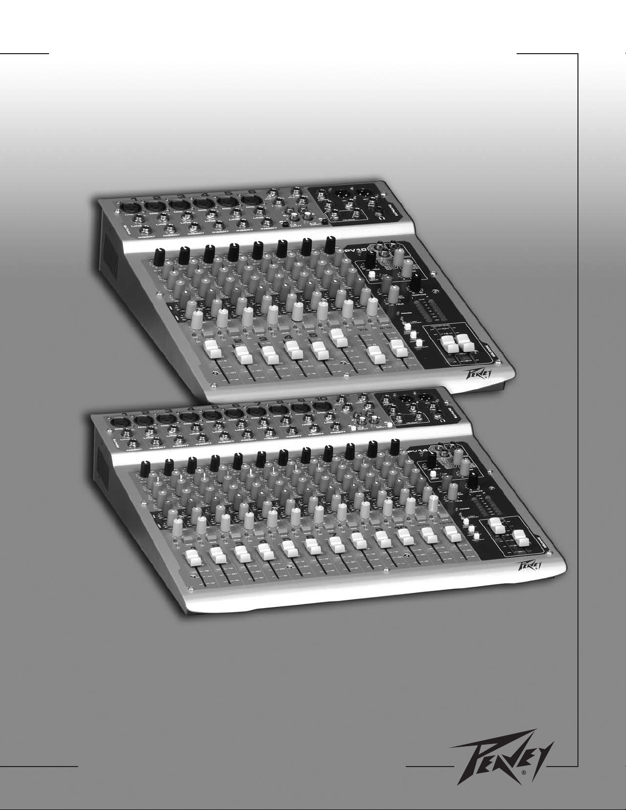
PV®10 and PV®14
Compact Mixer Operations Guide
For more information on other great Peavey products, visit your local Peavey dealer or go online to www.peavey.com
Page 2
Intended to alert the user to the presence of uninsulated “dangerous voltage” within the product’s
enclosure that may be of sufficient magnitude to constitute a risk of electric shock to persons.
Intended to alert the user of the presence of important operating and maintenance (servicing)
instructions in the literature accompanying the product.
CCAAUUTTIIOONN::
CCAAUUTTIIOONN::
Risk of electrical shock — DO NOT OPEN!
To reduce the risk of electric shock, do not remove cover. No user serviceable parts inside.
Refer servicing to qualified service personnel.
WWAARRNNIINNGG::
To prevent electrical shock or fire hazard, do not expose this appliance to rain or moisture.
Before using this appliance, read the operating guide for further warnings.
Este símbolo tiene el propósito, de alertar al usuario de la presencia de “(voltaje) peligroso” sin
aislamiento dentro de la caja del producto y que puede tener una magnitud suficiente como para
constituir riesgo de descarga eléctrica.
Este símbolo tiene el propósito de alertar al usario de la presencia de instruccones importantes sobre la
operación y mantenimiento en la información que viene con el producto.
PPRREECCAAUUCCIIOONN::
PPRREECCAAUUCCIIOONN::
Riesgo de descarga eléctrica ¡NO ABRIR!
Para disminuír el riesgo de descarga eléctrica, no abra la cubierta. No hay piezas útiles
dentro. Deje todo mantenimiento en manos del personal técnico cualificado.
AADDVVEERRTTEENNCCIIAA::
Para evitar descargas eléctricas o peligro de incendio, no deje expuesto a la lluvia o
humedad este aparato Antes de usar este aparato, Iea más advertencias en la guía de operación.
Ce symbole est utilisé dans ce manuel pour indiquer à l’utilisateur la présence d’une tension dangereuse
pouvant être d’amplitude suffisante pour constituer un risque de choc électrique.
Ce symbole est utilisé dans ce manuel pour indiquer à l’utilisateur qu’il ou qu’elle trouvera d’importantes
instructions concernant l’utilisation et l’entretien de l’appareil dans le paragraphe signalé.
AATTTTEENNTTIIOONN::
AAT
TTTEENNTTIIOONN::
Risques de choc électrique — NE PAS OUVRIR!
Afin de réduire le risque de choc électrique, ne pas enlever le couvercle. Il ne se trouve à
l’intérieur aucune pièce pouvant être reparée par l’utilisateur. Confiez I’entretien et la réparation de
l’appareil à un réparateur Peavey agréé.
AAVVEERRTTIISSSSEEMMEENNTT
: Afin de prévenir les risques de décharge électrique ou de feu, n’exposez pas cet
appareil à la pluie ou à l’humidité. Avant d’utiliser cet appareil, lisez attentivement les avertissements
supplémentaires de ce manuel.
Dieses Symbol soll den Anwender vor unisolierten gefährlichen Spannungen innerhalb des Gehäuses
warnen, die von Ausreichender Stärke sind, um einen elektrischen Schlag verursachen zu können.
Dieses Symbol soll den Benutzer auf wichtige Instruktionen in der Bedienungsanleitung aufmerksam
machen, die Handhabung und Wartung des Produkts betreffen.
VVOORRSSIICCHHTT::
VVOORRSSIICCHHTT::
Risiko — Elektrischer Schlag! Nicht öffnen!
Um das Risiko eines elektrischen Schlages zu vermeiden, nicht die Abdeckung enfernen. Es
befinden sich keine Teile darin, die vom Anwender repariert werden könnten. Reparaturen nur von
qualifiziertem Fachpersonal durchführen lassen.
AACCHHTTUUNNGG::
Um einen elektrischen Schlag oder Feuergefahr zu vermeiden, sollte dieses Gerät nicht dem
Regen oder Feuchtigkeit ausgesetzt werden. Vor Inbetriebnahme unbedingt die Bedienungsanleitung lesen.
2
Page 3
IIMMPPOORRTTAANNTT SSAAFFEETTYY IINNSSTTRRUUCCTTIIOONNSS
WWAARRNNIINNGG::
When using electrical products, basic cautions should always be followed, including the following:
1. Read these instructions.
2. Keep these instructions.
3. Heed all warnings.
4. Follow all instructions.
5. Do not use this apparatus near water.
6. Clean only with a dry cloth.
7. Do not block any of the ventilation openings. Install in accordance with manufacturer’s instructions.
8. Do not install near any heat sources such as radiators, heat registers, stoves or other apparatus (including
amplifiers) that produce heat.
9. Do not defeat the safety purpose of the polarized or grounding-type plug. A polarized plug has two blades with one
wider than the other. A grounding type plug has two blades and a third grounding plug. The wide blade or third
prong is provided for your safety. If the provided plug does not fit into your outlet, consult an electrician for
replacement of the obsolete outlet.
10. Protect the power cord from being walked on or pinched, particularly at plugs, convenience receptacles, and the
point they exit from the apparatus.
11. Note for UK only: If the colors of the wires in the mains lead of this unit do not correspond with the terminals in your
plug‚ proceed as follows:
a) The wire that is colored green and yellow must be connected to the terminal that is marked by the letter E‚ the
earth symbol‚ colored green or colored green and yellow.
b) The wire that is colored blue must be connected to the terminal that is marked with the letter N or the color black.
c) The wire that is colored brown must be connected to the terminal that is marked with the letter L or the color red.
12. Only use attachments/accessories provided by the manufacturer.
13. Use only with a cart, stand, tripod, bracket, or table specified by the manufacturer, or sold with the apparatus. When
a cart is used, use caution when moving the cart/apparatus combination to avoid injury from tip-over.
14. Unplug this apparatus during lightning storms or when unused for long periods of time.
15. Refer all servicing to qualified service personnel. Servicing is required when the apparatus has been damaged in
any way, such as power-supply cord or plug is damaged, liquid has been spilled or objects have fallen into the
apparatus, the apparatus has been exposed to rain or moisture, does not operate normally, or has been dropped.
16. Never break off the ground pin. Write for our free booklet “Shock Hazard and Grounding.” Connect only to a power
supply of the type marked on the unit adjacent to the power supply cord.
17. If this product is to be mounted in an equipment rack, rear support should be provided.
18. Exposure to extremely high noise levels may cause a permanent hearing loss. Individuals vary considerably in
susceptibility to noise-induced hearing loss, but nearly everyone will lose some hearing if exposed to sufficiently
intense noise for a sufficient time. The U.S. Government’s Occupational and Health Administration (OSHA) has
specified the following permissible noise level exposures:
Duration Per Day In Hours Sound Level dBA, Slow Response
890
692
495
397
2 100
1 1⁄
2
1 105
1
⁄
2
1
⁄4or less 115
According to OSHA, any exposure in excess of the above permissible limits could result in some hearing loss. Ear plugs or protectors to the
ear canals or over the ears must be worn when operating this amplification system in order to prevent a permanent hearing loss, if exposure
is in excess of the limits as set forth above. To ensure against potentially dangerous exposure to high sound pressure levels, it is
recommended that all persons exposed to equipment capable of producing high sound pressure levels such as this amplification system be
protected by hearing protectors while this unit is in operation.
102
110
SSAAVVEE TTHHEESSEE IINNSSTTRRUUCCTTIIOONNSS!!
3
Page 4
WWIICCHHTTIIGGEE SSIICCHHEERRHHEEIITTSSHHIINNWWEEIISSEE
AACCHHTTUUNNGG::
Beim Einsatz von Elektrogeräten müssen u.a. grundlegende Vorsichtsmaßnahmen befolgt werden:
1. Lesen Sie sich diese Anweisungen durch.
2. Bewahren Sie diese Anweisungen auf.
3. Beachten Sie alle Warnungen.
4. Befolgen Sie alle Anweisungen.
5. Setzen Sie dieses Gerät nicht in der Nähe von Wasser ein.
6. Reinigen Sie es nur mit einem trockenen Tuch.
7. Blockieren Sie keine der Lüftungsöffnungen. Führen Sie die Installation gemäß den Anweisungen des Herstellers durch.
8. Installieren Sie das Gerät nicht neben Wärmequellen wie Heizungen, Heizgeräten, Öfen oder anderen Geräten (auch Verstärkern),
die Wärme erzeugen.
9. Beeinträchtigen Sie nicht die Sicherheitswirkung des gepolten Steckers bzw. des Erdungssteckers. Ein gepolter Stecker weist
zwei Stifte auf, von denen einer breiter ist als der andere. Ein Erdungsstecker weist zwei Stifte und einen dritten Erdungsstift auf.
Der breite Stift bzw. der dritte Stift dient Ihrer Sicherheit. Sollte der beiliegende Stecker nicht in Ihre Steckdose passen, wenden
Sie sich bitte an einen Elektriker, um die ungeeignete Steckdose austauschen zu lassen.
10. Schützen Sie das Netzkabel, sodass niemand darauf tritt oder es geknickt wird, insbesondere an Steckern oder Buchsen und
ihren Austrittsstellen aus dem Gerät.
11. Hinweis – Nur für Großbritannien: Sollte die Farbe der Drähte in der Netzleitung dieses Geräts nicht mit den Klemmen in Ihrem
Stecker übereinstimmen, gehen Sie folgendermaßen vor:
a) Der grün-gelbe Draht muss an die mit E (Symbol für Erde) markierte bzw. grüne oder grün-gelbe Klemme angeschlossen
werden.
b) Der blaue Draht muss an die mit N markierte bzw. schwarze Klemme angeschlossen werden.
c) Der braune Draht muss an die mit L markierte bzw. rote Klemme angeschlossen werden.
12. Verwenden Sie nur die vom Hersteller erhältlichen Zubehörgeräte oder Zubehörteile.
13. Verwenden Sie nur einen Wagen, Stativ, Dreifuß, Träger oder Tisch, der den Angaben des Herstellers entspricht oder zusammen
mit dem Gerät verkauft wurde. Wird ein Wagen verwendet, bewegen Sie den Wagen mit dem darauf befindlichen Gerät besonders
vorsichtig, damit er nicht umkippt und möglicherweise jemand verletzt wird.
14. Trennen Sie das Gerät während eines Gewitters oder während längerer Zeiträume, in denen es nicht benutzt wird, von der
Stromversorgung.
15. Lassen Sie sämtliche Wartungsarbeiten von qualifizierten Kundendiensttechnikern durchführen. Eine Wartung ist erforderlich,
wenn das Gerät in irgendeiner Art beschädigt wurde, etwa wenn das Netzkabel oder der Netzstecker beschädigt wurden,
Flüssigkeit oder Gegenstände in das Gerät gelangt sind, das Gerät Regen oder Feuchtigkeit ausgesetzt wurde, nicht normal
arbeitet oder heruntergefallen ist.
16. Der Erdungsstift darf nie entfernt werden. Auf Wunsch senden wir Ihnen gerne unsere kostenlose Broschüre „Shock Hazard and
Grounding“ (Gefahr durch elektrischen Schlag und Erdung) zu. Schließen Sie nur an die Stromversorgung der Art an, die am
Gerät neben dem Netzkabel angegeben ist.
17. Wenn dieses Produkt in ein Geräte-Rack eingebaut werden soll, muss eine Versorgung über die Rückseite eingerichtet werden.
18. Belastung durch extrem hohe Lärmpegel kann zu dauerhaftem Gehörverlust führen. Die Anfälligkeit für durch Lärm bedingten
Gehörverlust ist von Mensch zu Mensch verschieden, das Gehör wird jedoch bei jedem in gewissem Maße geschädigt, der über
einen bestimmten Zeitraum ausreichend starkem Lärm ausgesetzt ist. Die US-Arbeitsschutzbehörde (Occupational and Health
Administration, OSHA) hat die folgenden zulässigen Pegel für Lärmbelastung festgelegt:
Dauer pro Tag in Stunden Geräuschpegel dBA, langsame Reaktion
890
692
495
397
2 100
1 1⁄
2
1 105
1
⁄
1
⁄4oder weniger 115
Laut OSHA kann jede Belastung über den obenstehenden zulässigen Grenzwerten zu einem gewissen Gehörverlust führen. Sollte die
Belastung die obenstehenden Grenzwerte übersteigen, müssen beim Betrieb dieses Verstärkungssystems Ohrenstopfen oder
Schutzvorrichtungen im Gehörgang oder über den Ohren getragen werden, um einen dauerhaften Gehörverlust zu verhindern. Um sich vor
einer möglicherweise gefährlichen Belastung durch hohe Schalldruckpegel zu schützen, wird allen Personen empfohlen, die mit Geräten
arbeiten, die wie dieses Verstärkungssystem hohe Schalldruckpegel erzeugen können, beim Betrieb dieses Geräts einen Gehörschutz zu tragen.
2
102
110
BBEEWWAAHHRREENN SSIIEE DDIIEESSEE SSIICCHHEERRHHEEIITTSSHHIINNWWEEIISSEE AAUUFF!!
4
Page 5
IINNSSTTRRUUCCTTIIOONNSS IIMMPPOORRTTAANNTTEESS DDEE SSEECCUURRIITTEE
AATTTTEENNTTIIOONN::
L’utilisation de tout appareil électrique doit être soumise aux precautions d’usage incluant:
1. Lire ces instructions.
2. Gardez ce manuel pour de futures références.
3. Prétez attention aux messages de précautions de ce manuel.
4. Suivez ces instructions.
5. N’utilisez pas cette unité proche de plans d’eau.
6. N’utilisez qu’un tissu sec pour le nettoyage de votre unité.
7. N’obstruez pas les systèmes de refroidissement de votre unité et installez votre unité en fonction des instructions
de ce manuel.
8. Ne positionnez pas votre unité à proximité de toute source de chaleur.
9. Connectez toujours votre unité sur une alimentation munie de prise de terre utilisant le cordon d’alimentation
fourni.
10. Protégez les connecteurs de votre unité et positionnez les cablages pour éviter toutes déconnexions accidentelles.
11. Note pour les Royaumes-Unis: Si les couleurs de connecteurs du cable d’alimentation ne correspond pas au guide
de la prise secteur, procédez comme suit:
a) Le connecteur vert et jaune doit être connectrer au terminal noté E, indiquant la prise de terre ou correspondant
aux couleurs verte ou verte et jaune du guide.
b) Le connecteur Bleu doit être connectrer au terminal noté N, correspondnat à la couleur noire du guide.
c) Le connecteur marron doit être connectrer au terminal noté L, correspondant à la couleur rouge du guide..
12. N’utilisez que des fixations approuvées par le fabriquant.
13. Lors de l’utilsation sur pied ou pole de support, assurez dans le cas de déplacement de l’ensemble
enceinte/support de prévenir tout basculement intempestif de celui-ci.
14. Il est conseillé de déconnecter du secteur votre unité en cas d’orage ou de durée prolongée sans utilisation.
15. Seul un technicien agréé par le fabriquant est à même de réparer/contrôler votre unité. Celle-ci doit être contrôlée si
elle a subit des dommages de manipulation, d’utilisation ou de stockage (humidité,…).
16. Ne déconnectez jamais la prise de terre de votre unité.
17. Si votre unité est destinée a etre montée en rack, des supports arriere doivent etre utilises.
18. Une exposition à de hauts niveaux sonores peut conduire à des dommages de l’écoute irréversibles. La susceptibilité au bruit varie considérablement d’un individu à l’autre, mais une large majorité de la population expériencera
une perte de l’écoute après une exposition à une forte puissance sonore pour une durée prolongée. L’organisme de
la santé américaine (OSHA) a produit le guide ci-dessous en rapport à la perte occasionnée:
Durée par Jour (heures) Niveau sonore moyen (dBA)
890
692
495
397
2 100
1 1⁄
2
1 105
1
⁄
2
1
⁄4ou inférieur 115
D’après les études menées par le OSHA, toute exposition au delà des limites décrites ce-dessus entrainera des pertes de l’écoute chez la plupart des sujets. Le port de système de protection (casque, oreilette de filtrage,…) doit être observé lors de l’opération cette unité ou des
dommages irréversibles peuvent être occasionnés. Le port de ces systèmes doit être observé par toutes personnes susceptibles d’être
exposées à des conditions au delà des limites décrites ci-dessus.
102
110
GGAARRDDEEZZ CCEESS IINNSSTTRRUUCCTTIIOONNSS!!
5
Page 6

IINNSSTTRRUUCCCCIIOONNEESS IIMMPPOORRTTAANNTTEESS PPAARRAA SSUU SSEEGGUURRIIDDAADD
CCUUIIDDAADDOO::
Cuando use productos electrónicos, debe tomar precauciones básicas, incluyendo las siguientes:
1. Lea estas instrucciones.
2. Guarde estas instrucciones.
3. Haga caso de todos los consejos.
4. Siga todas las instrucciones.
5. No usar este aparato cerca del agua.
6. Limpiar solamente con una tela seca.
7. No bloquear ninguna de las salidas de ventilación. Instalar de acuerdo a las instrucciones del fabricante.
8. No instalar cerca de ninguna fuente de calor como radiadores, estufas, hornos u otros aparatos (incluyendo amplificadores)
que produzcan calor.
9. No retire la patilla protectora del enchufe polarizado o de tipo “a Tierra”. Un enchufe polarizado tiene dos puntas, una de
ellas más ancha que la otra. Un enchufe de tipo “a Tierra” tiene dos puntas y una tercera “a Tierra”. La punta ancha ( la
tercera ) se proporciona para su seguridad. Si el enchufe proporcionado no encaja en su enchufe de red, consulte a un
electricista para que reemplaze su enchufe obsoleto.
10. Proteja el cable de alimentación para que no sea pisado o pinchado, particularmente en los enchufes, huecos, y los puntos
que salen del aparato.
11. Nota para el Reino Unido solamente: Si los colores de los cables en el enchufe principal de esta unidad no corresponden
con los terminales en su enchufe‚ proceda de la siguiente manera:
a) El cable de color verde y azul debe ser conectado al terminal que está marcado con la letra E‚ el símbolo de Tierra
(earth)‚ coloreado en verde o en verde y amarillo.
b) El cable coloreado en azul debe ser conectado al terminal que está marcado con la letra N o el color negro.
c) El cable coloreado en marrón debe ser conectado al terminal que está marcado con la letra L o el color rojo.
12. Usar solamente añadidos/accesorios proporcionados por el fabricante.
13. Usar solamente un carro, pie, trípode, o soporte especificado por el fabricante, o vendido junto al aparato. Cuando se use
un carro, tenga cuidado al mover el conjunto carro/aparato para evitar que se dañe en un vuelco. No suspenda esta caja de
ninguna manera.
14. Desenchufe este aparato durante tormentas o cuando no sea usado durante largos periodos de tiempo.
15. Para cualquier reparación, acuda a personal de servicio cualificado. Se requieren reparaciones cuando el aparato ha sido
dañado de alguna manera, como cuando el cable de alimentación o el enchufe se han dañado, algún líquido ha sido
derramado o algún objeto ha caído dentro del aparato, el aparato ha sido expuesto a la lluvia o la humedad, no funciona de
manera normal, o ha sufrido una caída.
16. Nunca retire la patilla de Tierra.Escríbanos para obtener nuestro folleto gratuito “Shock Hazard and Grounding” (“Peligro
de Electrocución y Toma a Tierra”). Conecte el aparato sólo a una fuente de alimentación del tipo marcado al lado del cable
de alimentación.
17. Si este producto va a ser enracado con más equipo, use algún tipo de apoyo trasero.
18. La exposición a altos niveles de ruido puede causar una pérdida permanente en la audición. La susceptibilidad a la pérdida
de audición provocada por el ruido varía según la persona, pero casi todo el mundo perderá algo de audición si se expone a
un nivel de ruido suficientemante intenso durante un tiempo determinado. El Departamento para la Salud y para la
Seguridad del Gobierno de los Estados Unidos (OSHA) ha especificado las siguientes exposiciones al ruido permisibles:
Duración por Día en Horas Nivel de Sonido dBA, Respuesta Lenta
890
692
495
397
2 100
1 1⁄
2
1 105
1
⁄
2
1
⁄4o menos 115
De acuerdo al OSHA, cualquier exposición que exceda los límites arriba indicados puede producir algún tipo de pérdida en la audición.
Protectores para los canales auditivos o tapones para los oídos deben ser usados cuando se opere con este sistema de sonido para prevenir
una pérdida permanente en la audición, si la exposición excede los límites indicados más arriba. Para protegerse de una exposición a altos
niveles de sonido potencialmente peligrosa, se recomienda que todas las personas expuestas a equipamiento capaz de producir altos niveles de presión sonora, tales como este sistema de amplificación, se encuentren protegidas por protectores auditivos mientras esta unidad
esté operando.
102
110
GGUUAARRDDEE EESSTTAASS IINNSSTTRRUUCCCCIIOONNEESS!!
6
Page 7

EENNGGLLIISSHH
PV®10 and PV®14 Compact Mixers
Description
Congratulations on purchasing the Peavey PV 10 or PV 14 compact mixer. The PV 10 and PV 14 are studio-quality mixing consoles
designed to meet diverse needs while occupying only a small space. These are the perfect consoles for small venue performances or
home recording environments. PV series mixers feature built-in DSP effects that are useful in real-world recording and sound
reinforcement, and parameter controls allow you to tailor each effect to meet your needs.
Please read this guide carefully to ensure your personal safety as well as the safety of your equipment.
Features
➡ Six XLR mic inputs on PV 10, ten XLR mic inputs on PV 14
➡ Two stereo channels with RCA and 1⁄4" inputs
➡ Three-band channel EQ
➡ A/B stereo input selector reduces patching
➡ Inserts on all mono channels
➡ 80 Hz low-cut switch on all mic inputs
➡ Clip LEDs monitor the entire signal path for clipping
➡ Signal LEDs on every input channel
➡ Mute switches with LED indicator on every input channel
➡ 48 Volt phantom power switch
➡ Effects send on every channel with stereo return
➡ Internal digital effects with 16 selections, including reverb, delay and vocal enhancement
➡ Effect parameter adjustment allows you to customize each effect selection
➡ Monitor send on every channel
➡ Zero latency record monitoring capabilities
➡ Control room output with level control
➡ Contour EQ switch
➡ Internal universal input power supply
➡ Optional rack-mount kit
7
Page 8
FF RR OO NN TT PP AA NN EE LL
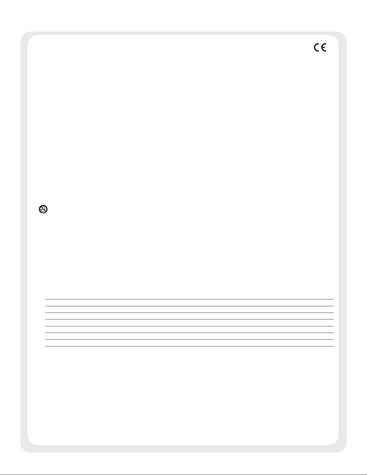
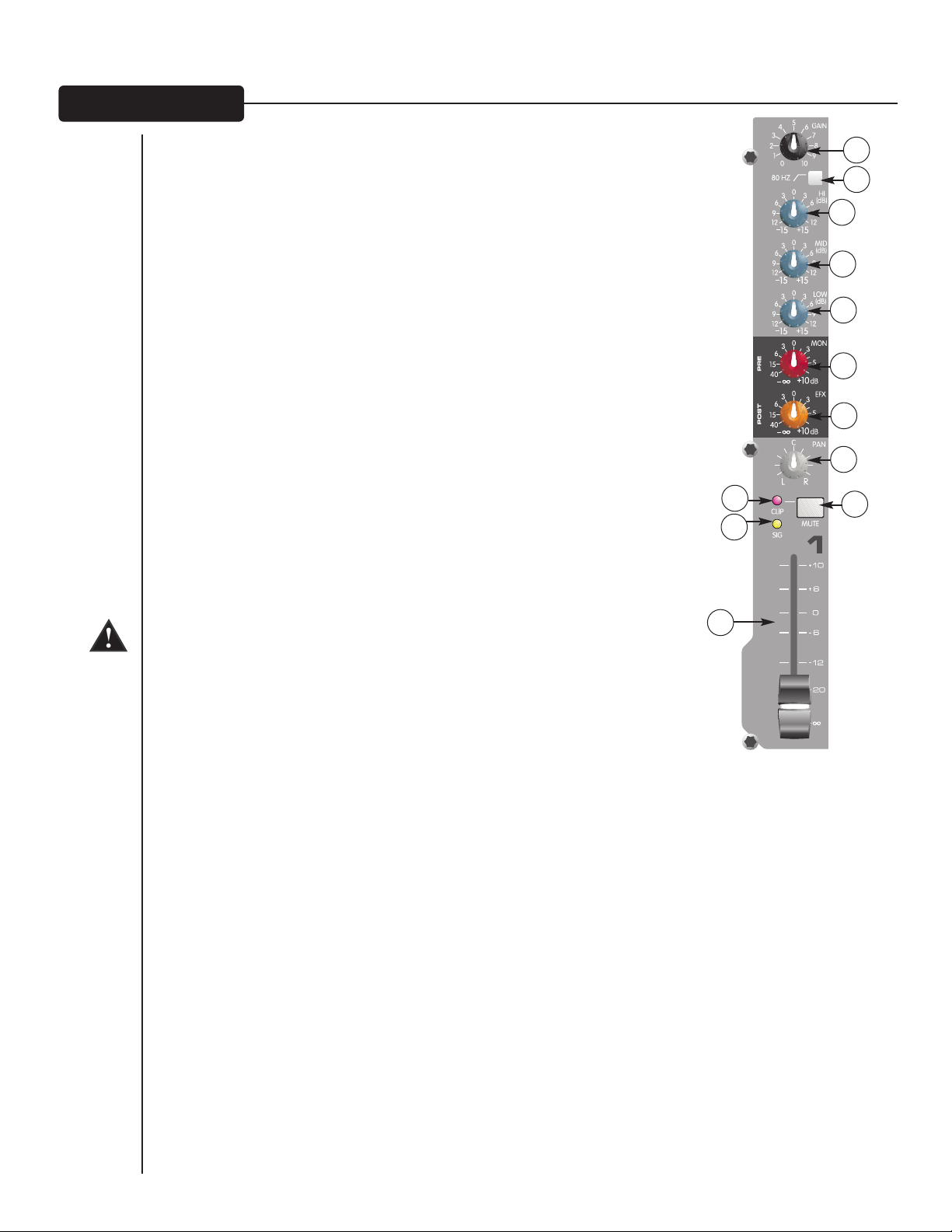
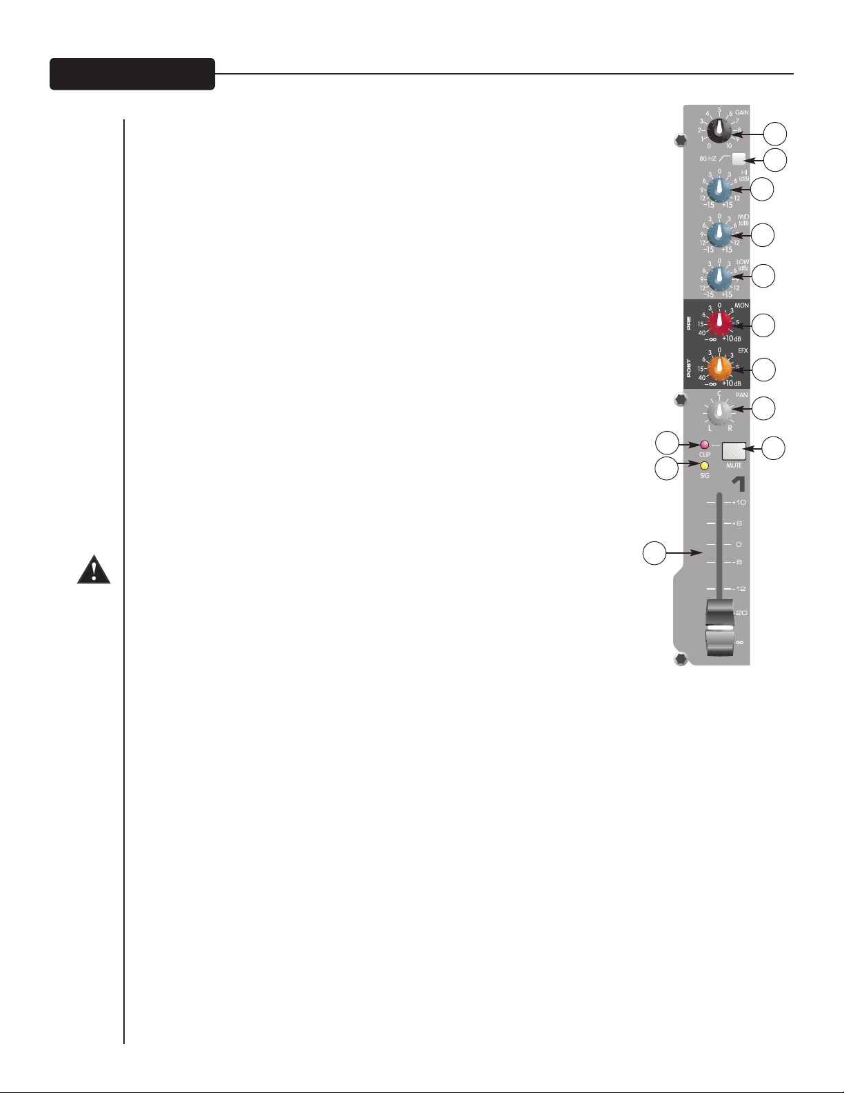
Gain (1)
This control establishes the nominal operating level for the channel. The input gain
can be adjusted over a wide range to compensate for soft voices or very loud
drums. To maximize the signal-to-noise ratio, the gain should be set to the proper
level, with the channel level control (12) set to 0. If the clip LED comes on and
remains lit, try reducing the gain.
80 Hz Low Cut (2)
The low cut filter has a corner frequency of 80 Hz. When engaged‚ it can improve
clarity by removing low frequencies that make a mix sound muddy. This feature is
especially useful when playing outside on a windy day or on a hollow-sounding‚
noisy stage. These kinds of ambient noises can rob your sound system of power.
Engaging this switch will remove those frequencies from the system and restore
power where needed.
Hi EQ (3)
An active tone control (shelving type: ±15 dB) that varies the level of the high
frequency range.
Mid EQ (4)
An active tone control (peak dip: ±15 dB) that varies the mid frequency range.
Low EQ (5)
An active tone control (shelving type: ±15 dB) that varies the level of the low
frequency range.
Caution: Excessive low frequency boost causes greater power consumption and increases the
possibility of speaker damage.
12
10
11
1
2
3
4
5
6
7
8
9
MON Send (6)
This control adjusts the level of the channel signal sent to the monitor output. The
signal is taken before the channel level control but after the channel EQ.
EFX Send (7)
This control adjusts the level of the channel signal added to the effects mix. The effects send signal is taken
after the channel fader (12) so that adjustments made to the fader will also affect the send level.
Pan (8)
This knob controls the placement of the signal in the stereo field. When rotated completely counterclockwise‚
the signal is present only on the left channel; when rotated completely clockwise‚ only in the right channel. On
stereo channels 5/6 and 7/8 on the PV 10, (11/12 and 13/14 on the PV 14), this control functions as a balance
control to adjust the relative level of the left and right signals.
Mute (9)
The mute button is a quick way to remove the channel signal from the left/right main mix, effects and monitor
sends without disturbing the control setting.
Clip/Mute LED (10)
This light normally indicates that the channel signal level is nearing the overload point, but it also lights when
mute is engaged. The clip indicator circuit monitors the signal at many points in the channel to ensure that it
catches all instances of clipping. It illuminates at +19 dBu and warns that the gain or EQ boost should be
reduced. When it lights, roughly 3 dB of headroom remain.
8
Page 9
Signal LED (11)
The signal LED lights when the channel level reaches approximately -20 dBu. This not only indicates which
channels are active, but also serves as a mini level meter.
Fader (12)
The channel fader is the channel output control and sets the signal level to the left and right mix and the effects
send control. The optimum setting is the 0 (unity gain) position.
13
14
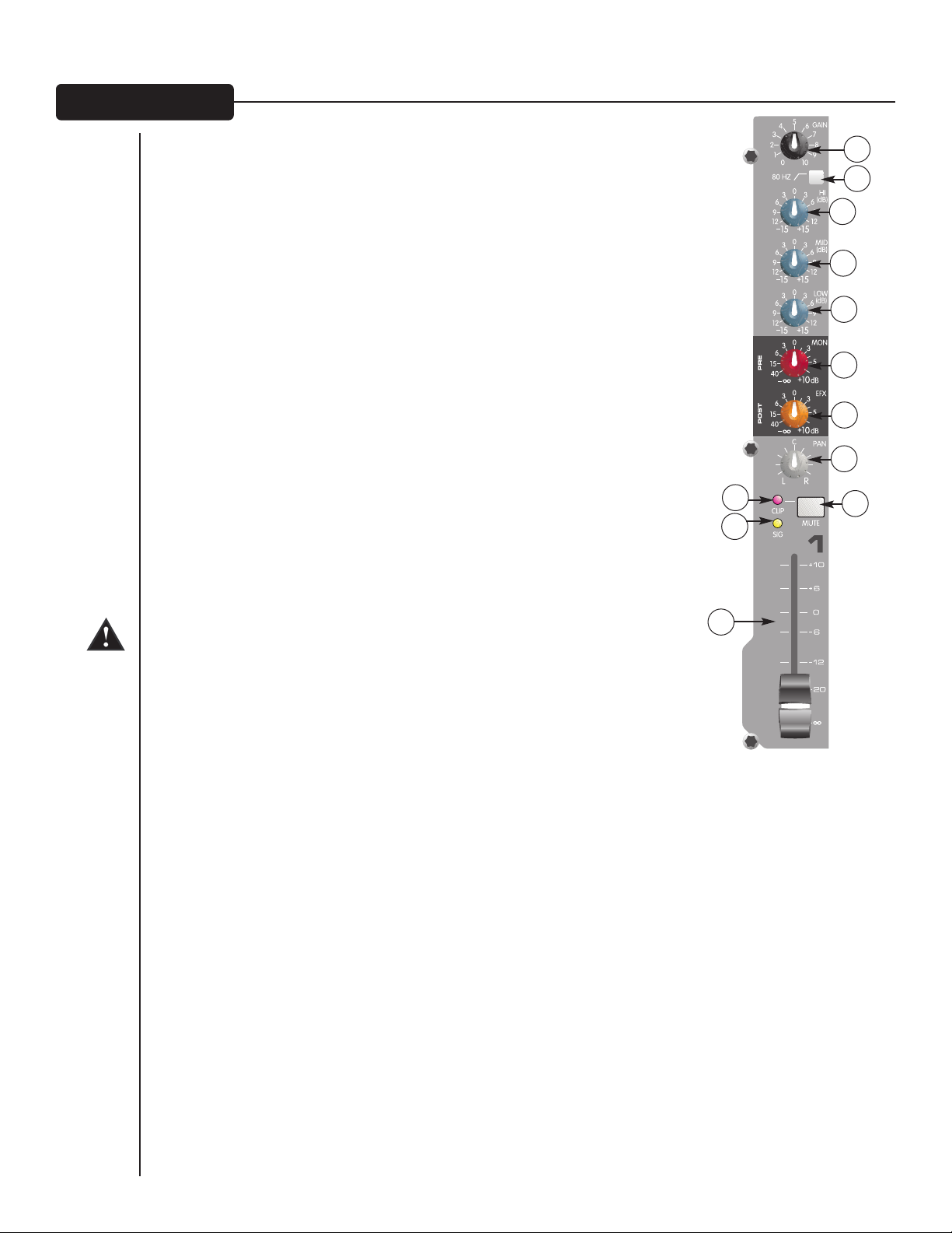
Tape In/Out (13 & 14)
The tape input jacks are designed to accommodate tape‚ CD or
computer sound card output levels. The output level is +4 dBu for
connecting to a recorder or sound card input. The tape inputs can
be used as an additional stereo input by engaging the Tape to Main
Mix switch (27). The tape input can also be used to monitor the
recorder/sound card output without the risk of feedback.
18
15
EFX Select (15)
This rotary switch selects one of sixteen available effects. See the
table below for descriptions of each.
17
16
Effect Description
1
Hall Rev
2
Large Hall Rev
3
Room 1 Rev
4
Room 2 Rev
5
Plate 1 Rev
6
Plate 2 Rev
7
Cathedral
8
Spring
9
Delay 1
10
Delay 2
11
Delay 3
12
Tape Delay
13
Doubler
14
Shimmer
15
Vocal Enhancement 1
Medium Concert Hall
Larger Concert Hall Darker
Intimate Room Bright
Larger Room Darker
Bright
Darker
Large Space, Long and Darker
Classic Spring
Single Delay (Slap-back)
Warm Delay with Repeats
Dark Delay with Repeats
Warm Delay
Single Delay, 30 - 120 ms
Warm Delay with Modulation
Brightens and adds Room Reverb
Application
Ensemble
Gen Reverb
Pop Vocal
Drums, Rhythm
Pop Vocal
Drums
Choir
Guitar
Voc/Instr
Instruments
Instruments
Instruments
Instruments
Instruments
Vocals
Parameter
Rev Time
Rev Time
Rev Time
Rev Time
Rev Time
Rev Time
Rev Time
Rev Time
Dly Time
Dly Time
Dly Time
Dly Time/Feedback
Dly Time
Dly Time
Rev Level
16
Vocal Enhancement 2
EFX Time (16)
This control adjusts the time of the particular reverb or delay.
Brightens and adds Spring Reverb
9
Vocals
Rev Level
Page 10
Green Signal LED and Red Clip LED (17)
The green Signal LED and red Clip LED are used to set the operating input level to the PV®10 and PV®14
effects processors. The signal level to the processor is affected by channel fader, the effects send and the
effects send master controls. Start with the master control set to 0 (12 o'clock) and adjust the channel sends so
that the signal LED lights and the clip LED blinks on occasionally, if at all. The clip LED lights 6 db below
clipping. Pressing the EFX defeat mutes the effects signal and lights the clip/mute LED.
EFX Return (18)
Once the input level is set (see 17) use the EFX return control to mix the effects processor output into the
main left/right outputs. Remember, a little reverb goes a long way.
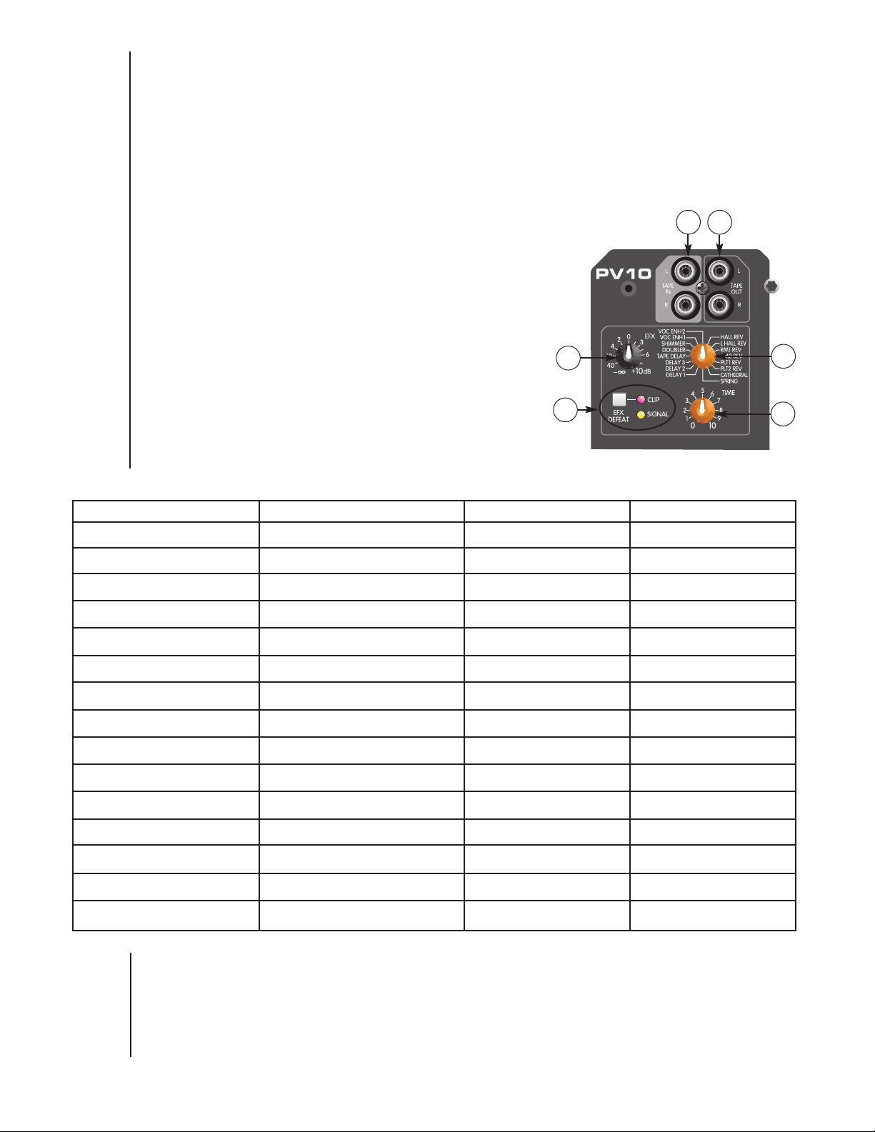
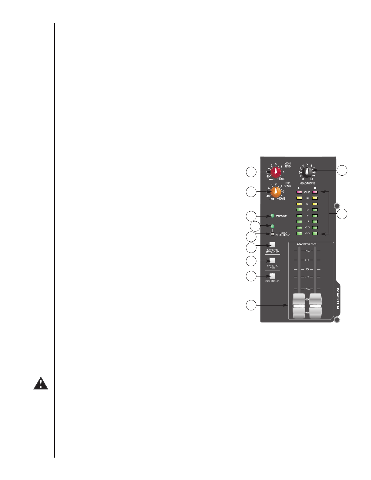
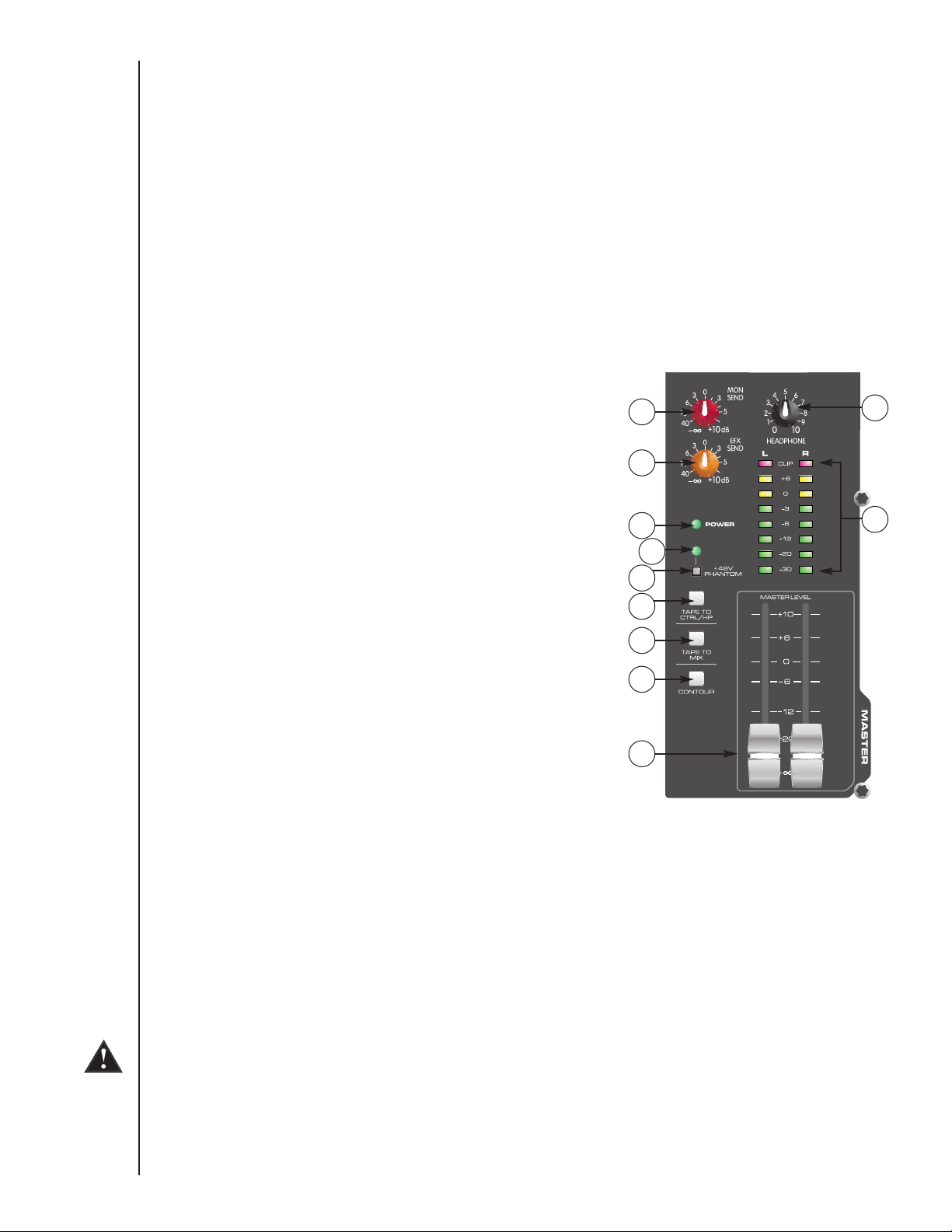
MON Send Master (19)
This is the master output level control for the monitor mix. The output level sent to the Monitor Send jack (36)
is controlled by the channel monitor send controls (6) and by this master control.
EFX Send Master (20)
This is the master output level control for the EFX mix. The output
level sent to the EFX Send jack and the internal effects processor is
controlled by the channel level controls (12), the channel EFX send
19
21
controls (7) and by this master control. The 0 position is the
recommended setting for this control.
20
Headphone Level (21)
This knob sets the headphone and control room output levels. To
avoid damage to your hearing‚ make sure to turn the dial fully
counterclockwise before using headphones. Slowly turn the knob
clockwise until you reach a comfortable listening level. Normally, the
signal in the headphones is the left/right signal. If the Tape to Control
Room (26) is engaged‚ the tape signal is also included.
23
24
25
26
22
LED Meters (22)
Two eight-segment LED arrays are provided to monitor the levels of
the main left/right outputs. These meters range from -30 dB to +19
27
28
dB. 0 dB on the meter corresponds to +4 dBu at the outputs.
Power LED (23)
29
This LED indicates AC power is supplied to the unit‚ the power
switch is on and the unit is functioning properly.
Phantom Power LED (24)
This LED lights when the Phantom Power Switch (25) has been engaged.
Phantom Power Switch (25)
Applies +48 VDC voltage to the input XLR connectors to power microphones requiring phantom power.
If phantom power is used, do not connect unbalanced dynamic microphones or other devices to the XLR inputs.
Tape To CTRL/HP (26)
Depressing this switch adds the tape return to the Control Room (38) and Headphone Outputs (40) for zero latency
monitoring.
Tape to Mix (27)
Depressing this switch routes the signal from the Tape Inputs (13) to the Main Outputs (39).
10
Page 11
Contour Switch (28)
Engaging this switch enhances the signal by adding both bass and treble frequencies. This is especially effective
at lower volumes or for tape/CD playback.
Master Level Faders (29)
The Master Faders control the levels sent to the main left/right outputs. Best results are obtained when these
controls are set near the 0 point.
RR EE AA RR PP AA NN EE LL
31
32
30
34
35
33
38
36 37
39
40
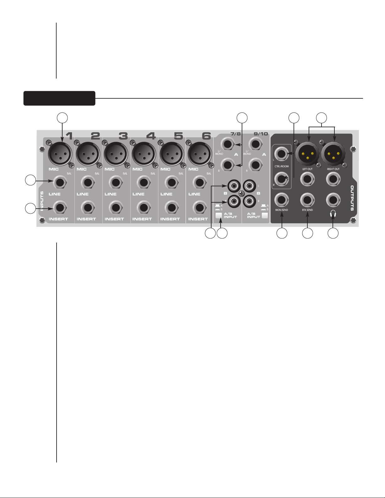
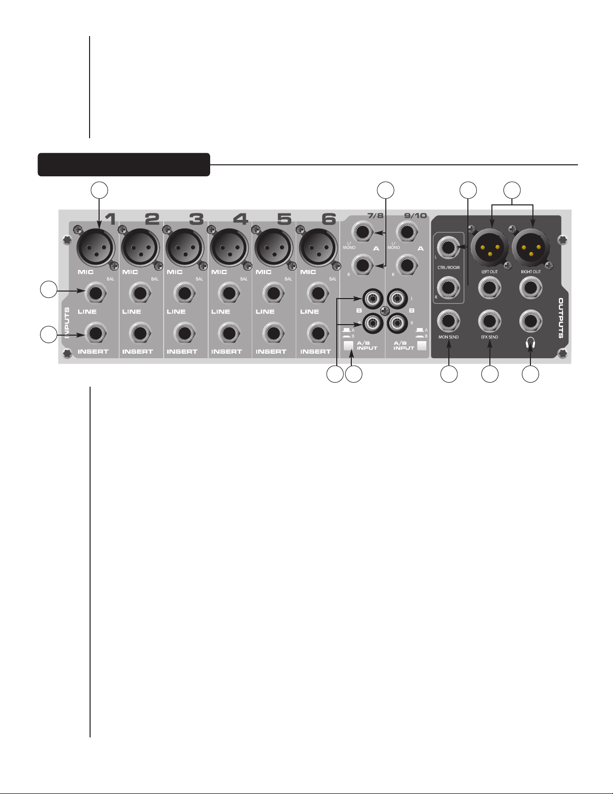
Mic (XLR) Inputs (30)
XLR balanced inputs optimized for a microphone or other low impedance source. Pin 2 is the positive input.
Because of the wide range of gain adjustment, signal levels up to +14 dBu can be accommodated.
Line (1⁄4”) Inputs (31)
1
⁄4” balanced (TRS) 10 k Ohm impedance input. The tip is the positive input and should be used for unbalanced
inputs. It has 20 dB less gain than the XLR input and does not have phantom power available. The Mic and Line
inputs should not be used simultaneously.
Insert (32)
1
⁄4” TRS connector allows external signal processors to be inserted into the channel signal path. Tip=Send;
Ring=Return; Sleeve=Ground.
Stereo (1⁄4") Inputs (33)
These 1⁄4" unbalanced inputs work as a stereo line input using both jacks or as a mono input if the connection is
made to the left/mono input only. The A/B input selector must be in the "A" position for these jacks to be
active.
RCA Inputs (34)
These RCA inputs work as stereo line inputs. The A/B input selector must be in the "B" position for these jacks
to be active.
A/B Switch (35)
The A/B input selector switch expands the capability of the PV®10 and the PV®14 mixers by allowing two
stereo sources to be connected to each stereo line input. Instead of repatching, the switch selects which input
jacks are active.
11
Page 12

MON Send (36)
The MON Send features a 1⁄4" TRS Z-balanced jack in the master section. This output can be used with the Tip, Ring,
Sleeve (TRS) balanced or Tip, Sleeve (TS) unbalanced connectors. The MON mix is determined by the amount of
signal being sent to the MON bus in each channel and by the Monitor master control.
EFX Send (37)
The EFX Send features a 1⁄4" TRS Z-balanced jack in the master section. These outputs can be used with Tip‚ Ring,
Sleeve (TRS) balanced or Tip, Sleeve (TS) unbalanced connectors. The EFX mix is determined by the amount of
signal being sent to the EFX bus in each channel and by the EFX master control.
Control Room Outputs (38)
The Control Room Outputs feature two 1⁄4
(TRS) balanced or Tip, Sleeve (TS) unbalanced connectors. The Control Room Output Level is adjusted with the
Headphone Level Control (21).
" TRS Z-balanced jacks. These outputs can be used with Tip, Ring, Sleeve
Left/Right Outputs (39)
The left/right Outputs feature two 1⁄4" TRS Z-balanced jacks and two fully balanced XLR outputs. The 1⁄4" outputs can
be used with Tip‚ Ring, Sleeve (TRS) balanced or Tip, Sleeve (TS) unbalanced connectors. The output level is set by
the Master Level faders (29). Both outputs can be used simultaneously.
Headphone Output (40)
The Headphone Output is a 1⁄4" TRS (tip= left; ring = right; sleeve = ground). The signal sent to this output is
normally the left/right mix. When the Tape to Control Room switch is engaged, the tape input signal is added to the
left/right mix and can be monitored in the headphones.
41
42
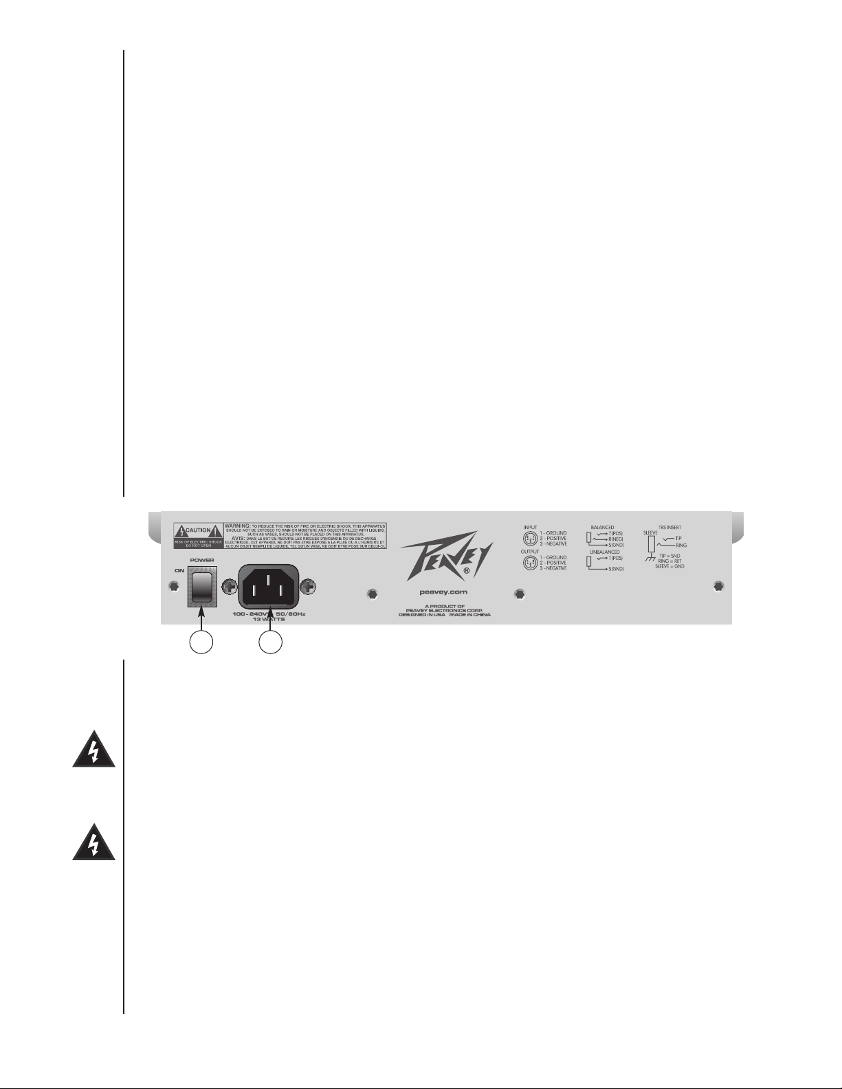
Power Switch (41)
Depressing the power switch supplies power to the unit.
Warning: The power switch in this unit breaks only one side of the line. There may be hazardous energy
present inside the mixer when the power switch is in the OFF position.
Removable Power Cord (42)
This receptacle is for the IEC line cord (included) that provides AC power to the unit. Connect the line cord to this
connector and to a properly grounded AC supply. Damage to the equipment may occur if an improper line voltage is
used (see voltage marking on unit). Never remove or cut the ground pin of the line cord plug. The console is
supplied with a properly rated line cord. If lost or damaged, replace this cord with one of the proper rating.
NOTE FOR UK ONLY:
If the colors of the wires in the mains lead of this unit do not correspond with the colored markings identifying
terminals in your plug, proceed as follows: (1) The wire that is colored green and yellow must be connected to the
terminal marked by the letter E, or by the earth symbol, or colored green or green and yellow. (2) The wire that is
colored blue must be connected to the terminal that is marked with the letter N, or colored black. (3) The wire that
is colored brown must be connected to the terminal that is marked with the letter L or colored red.
12
Page 13

CONTOUR
LO HI
Meridian, MS 39301
Peavey Electronics Corp.
P. O. Box 2898
Sheet Title:
Title:
Sheet
Date:
of
B
A
21
B
A
21
C
4
+48V
+
-
CONTOUR
LO HI
PAN
EQ
LO MID HI
EQ
LO MID HI
EQ
LO MID HI
80Hz
BALANCE
B
RIGHT
TAPE -L/R SELECT
POWER
PHANTOM
LINE
RIGHT
LEFT
XLR
LEFT/MONO
RIGHT
TAPE OUTPUT
HEADPHONES
CONTROL ROOM
TAPE TO MIX
TAPE INPUT
GLOBAL
CONTROL ROOM
TAPE TO
GAIN
EFX
MON
EFX
MON
LEFT/MONO
RIGHT
EFX
MON
LEFT
SELECT
INPUT
MON SEND
LED METER
EFX RETURN
INSERT
3-BAND EQ
LEVEL
CLIP/MUTE
CLIP/MUTE
EFX
DIGITAL
DEFEAT
EFX
EFX
SELECTOR
RETURN
EFX
ADJUST
TIME
MUTE
CLIP/
SIGNAL
MUTE
MUTE
EFX SEND
A
A/B
MAIN OUTPUTS
LEFT
RIGHT
LEFT
RIGHT
LOW-CUT
CHANNEL 11/12 - 13/14 (PV14)
CHANNEL 7/8 - 9/10 (PV10)
STEREO INPUT
CHANNEL 1-6 (PV10)
CHANNEL 1-10 (PV14)
MONO INPUT
2
3
1
PV14_BLOCK
6-15-2004_14:23 2 2
PV®10 and PV®14 Block Diagram
13
Page 14

PPVV®1100 && PPVV®1144 CCoommppaacctt CCoonnssoollee
Inputs
Function
Microphone
(150 Ohms)
Line (10 k Ohms)
Stereo Line Input
Tape
0 dBu = 0.775 V (RMS)
** Min Input Level (sensitivity) is the smallest signal that will produce nominal output (+4 dBu) with channel and master faders set for
maximum gain.
* Nominal settings are defined as all controls set at 0 dB (or 50% rotation for rotary pots) except the gain adjustment pot which is as
specified.
Input Z
(Ohms min)
2.2 k
10 k
10 k
10 k
Input Gain
Setting
Max Gain
(60 dB)
Min Gain
(10 dB)
Max Gain
(40 dB)
Min Gain
(-10 dB)
Max Gain
(20 dB)
Nominal
N/A
(10 dB)
SSPPEECCIIFFIICCAATTIIOONNSS
Input Levels
Min**
-76 dBu
-24 dBu
-56 dBu
-10 dBu
-36 dBu
-21 dBu
-17 dBu
Nominal*
-56 dBu
-4 dBu
-36 dBu
+14 dBu
-16 dBu
-1 dBu
-10 dBV
Max
-38 dBu
+14 dBu
-18 dBu
+32 dBu
+2 dBu
+17 dBu
+12 dBu
Bal/Unbal
Bal
Bal
Unbal
Unbal
Connector
XLR Pin 1 Gnd
Pin 2 (+)‚ Pin 3 (-)
1
⁄4"TRS; Tip (+)‚
Ring (-)‚ Sleeve
Ground
1
⁄4" TS; Tip (+)‚
Sleeve Ground
RCA Phono
Outputs
Function
Main Left/Right
Effects and
Monitor Sends
Control Room
Headphone
Tape
0 dBu = 0.775 V (RMS)
Min Load Z
(Ohms)
600
600
600
8
2.2 k
Nominal
+4 dBu
+4 dBu
+4 dBu
+4 dBu (no load)
+4 dBu
Output Level
Max
+22 dBu
+22 dBu
+22 dBu
+22 dBu
+22 dBu
Gain
Mic Input Gain Adjustment Range: 10 dB to 60 dB
Mic Input to Left/Right Balance Output 88 dB (max gain)
Line Input Gain Adjustment Range: -10 dB to 40 dB
Line Input to Left/Right Balance Output 60 dB (max gain)
Stereo Line Input Gain Adjustment Range: Off to +20 dB
Stereo Line Input to Left/Right Output 40 dB (max gain)
Bal/Unbal
Bal
Bal
Bal
Unbal
Unbal
Connector
XLR Pin Ground Tip
Pin 2 (+), Pin 3 (-)
1
⁄4" TRS: Tip (+), Ring (-),
Sleeve Ground
1
⁄4" TRS, Tip (+)‚ Ring (-)
Sleeve Ground
1
⁄
4" TRS, Tip (+)‚ Ring (-)
Sleeve Ground
1
⁄4" TRS; Tip Left‚ Ring Right‚
Sleeve Ground
RCA Phono
14
Page 15

Frequency Response
Mic Input to Left/Right Output 14 Hz to 25 kHz +0 dB/-1 dB
Total Harmonic Distortion
<0.02% 20 Hz to 20 kHz Mic to Left/Right Output (10 Hz to 80 kHz BW)
<0.005% Typical (22 Hz to 22 kHz BW)
<0.0007% Mic Pre-amp Distortion
Hum and Noise
Output
Master Left/Right
Monitor Send
Effects Sends
(Hum and noise measurements: 22 Hz to 22 kHz BW)
Residual Noise
-97 dBu
-90 dBu
-83 dBu
-95 dBu
-80 dBu
-100 dBu
-80 dBu
S/N Ratio (Ref: +4 dBu)
101 dB
94 dB
87 dB
99 dB
84 dB
104 dB
84 dB
Test Conditions
Master Fader Down‚ Channel Levels Down
Master Fader Nominal‚ Channel Levels Down
Master Fader Nominal, Channel Faders Nominal,
Panned Odd Channels (left), Even Channels (right)
All controls off
All channel sends nominal, masters nominal
All controls off
All channel sends nominal, masters nominal
Equivalent Input Noise (EIN)
-129 dBu (input terminated with 150 Ohms)
Crosstalk/Attenuation
Adjacent Input Channels (1 kHz) >90 dB Mute Button Attenuation (1 kHz) >90 dB
Left to Right Outputs (1 kHz) >75 dB Channel Fader Kill (1 kHz) >85 dB
Common Mode Rejection Ratio (Mic Input)
50 dB minimum (20 Hz to 20 kHz)
70 dB typical @ 1 kHz
Meters
8 segment, peak reading (0 dB = +4 dBu)
Signal/Overload Indicators
Red LED lights 3 dB below clipping
Dimensions
PV 10: 12.125" wide x 14.75" deep x 3.5" high (30.80cm x 37.47cm x 8.89cm)
PV 14: 16.125" wide x 14.75" deep x 3.5" high (40.96cm x 37.47cm x 8.89cm)
Installation Note:
This unit must have the following clearances from any combustible surface: top: 8", sides: 12", back: 12"
Weight
PV 10: 9.3 lbs. (4.22 kg)
PV 14: 12.1 lbs. (5.49kg)
Power Requirements
PV 10: 100-240 VAC 50/60 Hz 13 Watts
PV 14: 100-240 VAC 50/60 Hz 17 Watts
15
Page 16

FFRRAANNÇÇAAIISS
PV®10 et PV®14 Console de Mixage Compacte
Description
Félicitations pour l’achat de la Peavey PV10 ou PV14, unité de mixage au format table. Les PV10 et PV14 sont idéales pour toutes
applications d’enregistrement ou de diffusion où la compacité du matériel est importante. Un processeur d’effet intégré leur permet
de s’accomoder de la plupart des demandes de sonorisation.
Merci de lire attentivement ce manuel pour votre propre sécurité et celle de votre unité.
Caractéristiques
➡ Six (PV10) ou dix (PV14) entrées XLR Micro
➡ Deux canaux Stéréo avec entrées Jack 1/4" (6.35mm)
➡ Egalisation trois-bandes par canal
➡ Sélecteur A/B d’entrée Stéréo
➡ Insertion d’effets sur chaque canal
➡ Filtre coupe-bas 80 Hz sur chaque entrée micro
➡ Contrôle d’écrètage à chaque étape du signal
➡ LEDs de niveau sur chaque canal
➡ Sélecteur de mise en veille (Mute) avec LED témoin sur chaque canal
➡ Alimantation Phantom 48V à interrupteur
➡ Envoi vers effet sur chaque canal avec retour d’effets Stéréo
➡ Processeur d’effets numérique avec 16 présélections incluant réverbération et répétition (Delay)
➡ Contrôle d’effet permettant un ajustement de l’effet sélectionné
➡ Envoi vers bus de retour de scène sur chaque canal
➡ Possibilité d’enregistrement sans retard (Zero Latency)
➡ Sortie d’écoute additionnelle (Control Room) avec contrôle niveau
➡ Interrupteur de contour (filtre égaliseur en sortie)
➡ Transformateur d’alimentation interne
➡ filtre coupe bas 80 Hz à interrupteur
16
Page 17
PP AA NN NN EE AA UU AA VV AA NN TT
Gain (1)
Ce contrôle vous permet d’ajuster la sensibilité d’entrée du canal correspondant,
celui-ci pouvant s’accommoder de la plupart des types de signaux. Pour maximiser
la qualité du signal, le niveau de celui-ci dans le canal doit être fait avec le niveau de
sortie ajusté à 0. Si la Led d’écrètage s’illumine de facon prolongée, le gain du signal
doit être réduit.
80 Hz Low Cut (2)
Ce filtre coupe-bas est fixé à 80Hz. Il vous permet de clarifier le signal en enlevant
les basses fréquences du signal source, nécessaire dans des situations de scènes
bruyantes ou soumises au vent. Ces bruits parasites gaspillent énormément la
puissance de votre système et les enlever du signal source vous permet d’optimiser
la puissance de votre système où nécessaire.
Hi EQ (3)
Réglage de tonalité actif de type escalier permettant de modifier les niveaux des
hautes fréquences de +/-15 dB.
Mid EQ (4)
Réglage de tonalité actif de type escalier permettant de modifier les niveaux des
fréquences médium de +/-15 dB.
Low EQ (5)
Réglage de tonalité actif de type escalier permettant de modifier les niveaux des
basses fréquences de +/-15 dB.
Attention: Un niveau excessif de basses fréquences augmente considérablement les
consommations en puissance et peut endommager vos hauts-parleurs.
12
11
10
1
2
3
4
5
6
7
8
9
MON Send (6)
Ce contrôle vous permet d’ajuster le niveau du signal envoyé au bus de retour de
scène (Monitor). Ce signal n’est pas affecté par le contrôle de niveau du canal, mais
par ses contrôles d’égalisation.
EFX Send (7)
Ce contrôle vous permet d’ajuster le niveau du signal envoyé au bus d’effet. Le niveau de ce signal est également
affecté par le contrôle de niveau du canal.
Pan (8)
Détermine la position du canal dans l’image stéréo. En augmentant ce contrôle, vers la gauche (sens contrehoraire), le signal diminuera dans le champ droit tout en augmentant dans le champ gauche et vice-versa. Sur les
canaux Stéréo (5/6 et 7/8), ils permettent d’ajuster les niveaux relatifs des signaux Droite et Gauche.
Mute (9)
Ce sélecteur vous permet de mettre le canal en mode silence. Vous permettant de facilement désactivé un canal
sans pour autant modifier les réglages de votre système.
Clip/Mute LED (10)
(Leds d’indication de seuil d’écrètage et de contrôle de status) Ces Leds vous indiquent lorsque le niveau du signal
est proche de la sensibilité maximale ou que le canal correspondant est en mode silence (9). Le circuit de détection
analyse le signal à toutes les étapes du routage de clui-ci et la LED s’illuminera pour indiquer un niveau de +19dBu,
prévenant que les contrôles de gain ou d’égalisation doivent être atténués. Ce seuil est environ 3dB avant écrètage.
17
Page 18

Signal LED (11)
Ces LED vous indiquent si le canal correspondant recoit un signal de niveau supérieur à -20 dBur.
Fader (12)
Ce contrôle vous permet d’ajuster le niveau du signal de sortie. Le niveau d’utilisation commun (gain unitaire) est
en position 0.
Tape In/Out (13 & 14)
Les entrées Tape vous permettent d’envoyer un signal à votre unité
depuis un lecteur K7, CD, une carte son d’ordinateur,… Elles
représentent effectivement une entrée Stéréo additionnelle. En
engageant l’interrupteur ‘Tape to Main Mix’ (27), ces entrées vous
permettent également de contrôler le niveau du signal de sortie de
votre enregistreur / carte son sans risque d’effet de boucle. Les sorties
ont quand à elles un niveau de +4 dBu et vous permettent de
connecter un enregistreur ou une carte son
EFX Select (15)
Ce sélecteur rotatif vous permet de choisir un des 16 effets
disponibles. Référez-vous au tableau ci-dessous pour les descriptions
de chacuns de ceux-ci..
Effet Description
1
Réverbération standard
2
Réverbération large
3
Réverbération courte 1
4
Réverbération courte 2
5
Réverbération plate 1
Salle de concert de taille moyenne
Salle de concert de grande taille
Courte et brillante
Courte et plate
Brillante
18
17
Application
Ensemble
Gen Reverb
Chant
Batterie, percussions
Chant
13
14
15
16
Paramètre
Temps de réverbération
Temps de réverbération
Temps de réverbération
Temps de réverbération
Temps de réverbération
6
Réverbération plate 2
7
Réverbération Cathédrale
8
Réverbération à ressort
9
Effet de répétition 1
10
Effet de répétition 2
11
Effet de répétition 3
12
Effet de répétition à bande
13
Doubler
14
Shimmer
15
Pré-sélection chant 1
16
Pré-sélection chant 2
EFX Time (16)
Ce contrôle vous permet d’ajuster l’effet sélectionné.
Plate
Grand espace, plate
dite classique à ressort
Simple répétition
Douces multiples répétitions
Agressives multiples répétitions
Doux
30 - 120 ms unique répétition
Douce répétitions avec effet
Claire avec réverbération courte
Claire avec réverbération dite ‘à ressort’
Batterie
Chorale
Guitare
Chant/ Instrument
Instruments
Instruments
Instruments
Instruments
Instruments
Chant
Chant
Temps de réverbération
Temps de réverbération
Temps de réverbération
Temps de répétition
Temps de répétition
Temps de répétition
Temps/Nombre de répétition
Temps de répétition
Temps de répétition
Niveau de réverbération
Niveau de réverbération
18
Page 19
Green Signal LED and Red Clip LED (17)
Ces deux LED vous permettent de contrôler le niveau du signal à l’entrée du processeur d’effets de votre
unité. Le niveau de ce signal est affecté par les faders des canaux, ainsi que les contrôles d’envoi d’effet et de
niveau général d’envoi d’effet. Débuter en positionnant le contrôle général sur 0 (’12 heures’) et ajuster le
contrôle du canal de facon à illuminer les LED de signal et d’écrètage de facon occasionnelle. La LED d’écrètage
s’illumine 6dB avant celui-ci. Engager le sélecteur EFX defeat désactive l’envoi au processeur d’effets et
illuminera la LED clip/Mute correspondante.
EFX Return (18)
Ce contrôle vous permet d’ajuster le niveau du signal à la sortie du processeur d’effets, vous permettant de
doser ceux-ci dans le mixage général.
MON Send Master (19)
Ce contrôle vous permet d’ajuster le niveau général du signal envoyé à la sortie ‘MON Send’ (36).
EFX Send Master (20)
Ce contrôle vous permet d’ajuster le niveau général du signal envoyé à la
sortie ‘EFX Send’ et au processeur d’effets interne de votre unité. La
position recommendée est sur le 0.
19
21
Headphone Level (21)
Ce contrôle vous permet d’ajuster le niveau du signal d’écoute (sortie
20
casque et sortie ‘Control Room’). Assurez-vous de positionner le volume
au minimum lors d’une première écoute, puis d’augmenter doucement
jusqu’au niveau désiré. Généralement, le signal d’écoute correspond au
sorties principales; si le sélecteur ‘Tape to Control Room’(13) est
engagé, le signal pré-enregistré (Tape) est ajouté au signal d’écoute.
LED Meters (22)
Deux rangées de 6 Leds vous pemettent de contrôler le niveau du signal
présents aux sorties principales Droite/Gauche. Ils sont gradués de -20 dB
à +19 dB et le 0 db de l’échelle correspond à +4 dBu aux sorties.
23
24
25
26
27
28
Power LED (23)
Cette LED vous indique si votre unité est sous tension.
29
Phantom Power LED (24)
Cette LED s’illumine pour vous indiquer que l’alimentation Phantom est
active.
Phantom Power Switch (25)
Cet interrupteur vous permet d’activer ou de désactiver l’alimentation Phantom de votre unité. Celle-ci se
traduit par une tension de 48V appliquées aux entrées XLR.
22
Si l’alimentation est active, assurez-vous de ne pas connecter aux connecteurs XLR des micros ou autres unités
de signal qui ne suppoteraient pas ce voltage. La Led témoin correspondante (10) vous indique le status de
l’alimentation Phantom.
Tape To CTRL/HP (26)
En activant cet interrupteur vous ajoutez le signal présent aux entrées ‘Tape Return’ au signal d’écoute (Control Room -
38) et casque (40).
Tape to Mix (27)
En activant cet interrupteur vous ajoutez le signal présent aux entrées ‘Tape Return’ au signal des sorties
principales (39).
19
Page 20
Contour Switch (28)
Cet interrupteur vous permet d’appliquer une égalisation pré-définie ajoutant à la fois des hautes et basses
fréquences pour une accentuation du relief sonore. Ce sélecteur est particulièrement efficace pour des
applications musicales à faible niveau.
Master Level Faders (29)
Ces faders vous permettent d’ajuster le niveau des sorties principales Droite/Gauche. Pour maximiser la qualité
du signal, le niveau de celui-ci sera ajusté à 0 (gain unitaire).
PP AA NN NN EE AA UU AA RR RR II ÈÈ RR EE
31
32
30
34
35
33
38
36 37
39
40
Mic (XLR) Inputs (30)
Ces entrées XLR symétrisées sont optimisées pour la connexion d’un microphone où toute source basseimpédance (Pin 2 positive). De part la large plage de sensibilité d’entrée, on pourra obtenir jusqu’à +14dB
d’augmentation.
Line (1⁄4”) Inputs (31)
Ce Jack 1/4” (6.35mm) symétrique (TRS) possède une impédance de 10 k Ohm (pointe positive) et vous
permet de connecter une source sonore asymétrique Sa sensibilité est de –20dB comparée à l’entrée XLR. Les
entrées XLR(Mic) et Jack(Line) du même canal ne devraient pas être utilisées en même temps.
Insert (32)
Ce Jack 1/4” (6.35mm) TRS (3-connecteurs) vous permet d’insérer un processeur externe d’effets sur le canal
correspondant (pointe: sortie ou envoie, anneau: entrée ou retour, corps: masse).
Stereo (1⁄4") Inputs (33)
Ces entrées sont Stéréo par l’intermédiaire de paires de Jack Mono ou Mono si seul l’entrée Left/Mono est
utilisée. Le sélecteur A/B d’entrée doit être en position A pour que ces entrées soient actives.
RCA Inputs (34)
Ces entrées RCA vous permettent de connecter toute source sonore de niveau ligne (lecteur K7, CD, …). Le
sélecteur A/B d’entrée doit être en position B pour que ces entrées soient actives.
A/B Switch (35)
Ce sélecteur vous permet de passer entre les entrés Jack ou RCA du canal correspondant sans nécessiter de
changement de connexions.
20
Page 21
MON Send (36)
La sortie Moniteur (retour de scène) est un Jack 1/4" symétrique (TRS). Cette sortie vous permet d’envoyer le signal
somme déterminé par les contrôles MON de chaque canal à un processeur externe. Cette sortie peut être utilisée
avec un Jacks 2 (TS) ou 3 (TRS) conducteurs.
EFX Send (37)
La sortie du bus d’effet est un Jack 1/4" symétrique (TRS). Cette sortie vous permet d’envoyer le signal somme
déterminé par les contrôles EFX de chaque canal à un processeur externe. Cette sortie peut être utilisée avec un
Jacks 2 (TS) ou 3 (TRS) conducteurs.
Control Room Outputs (38)
Les sorties d’écoute sont composées de deux Jack 1/4" symétriques (TRS). Ces sorties peuvent être utilisées avec
des Jacks 2 (TS) ou 3 (TRS) conducteurs. Le niveau du signal à ces sorties peut être ajusté grace au contrôle de
niveau de casque (21).
Left/Right Outputs (39)
Les sorties principales Droite/Gauche sont composées de deux Jack 1/4" symétriques (TRS). Ces sorties peuvent être
utilisées avec des Jacks 2 (TS) ou 3 (TRS) conducteurs.
Headphone Output (40)
La sortie du bus d’effet est un Jack 1/4" symétrique (TRS, pointe = gauche; anneau = droit; corps = masse).
Généralement, le signal d’écoute correspond au sorties principales; si le sélecteur ‘Tape to Control Room’(13) est
engagé, le signal pré-enregistré (Tape) est ajouté au signal d’écoute.
41
42
Power Switch (41)
Cet interrupteur vous permet de mettre votre unité sous/hors tension.
ATTENTION: Cet interrupteur ouvre le circuit en un seul endroit, il n’est pas impossible que de l’énergie
électrique soit présente dans votre unité dans cette condition.
Removable Power Cord (42)
Connectez ici le cordon d’alimentation de l’appareil. Ne jamais déconnecter ou omettre une bonne connection à la
terre pour votre unité. Si l’alimentation électrique n’est pas équipée de prise de terre, un adaptateur pourra être
utilisé et le connecteur de terre relié à la terre proprement. Assurez-vous que tous les élèments de votre système
sont correctement relié à la terre pour éviter toute décharge électrique.
NOTE POUR LES ROYAUMES UNIS:
Si les couleurs de connecteurs du cable d’alimentation ne correspond pas au guide de la prise secteur, procédez
comme suit: (1) Le connecteur vert et jaune doit être connectrer au terminal noté E, indiquant la prise de terre ou
correspondant aux couleurs verte ou verte et jaune du guide. (2) Le connecteur Bleu doit être connectrer au terminal
noté N, correspondnat à la couleur noire du guide. (3) Le connecteur marron doit être connectrer au terminal noté L,
correspondant à la couleur rouge du guide.
21
Page 22

EESSPPAAÑÑOOLL
PV®10 and PV®14 Mezcladores Compactos
Descripción
Felicidades por haber adquirido la mesa de mezclas compacta PV 10 o PV 14 de Peavey. Tanto la PV 10 como la PV 14 son mesas
de mezclas con calidad para estudio, diseñadas para cubrir distintas necesidades ocupando un espacio pequeño. Estas consolas son
perfectas para actuaciones en pequeñas salas o entornos de grabación domésticos. La serie PV de consolas incluye efectos DSP que
son útiles en grabaciones reales y sonido industrial, y los controles paramétricos le permiten ajustar cada efecto en la medida que lo
necesite.
Por favor lea esta guía cuidadosamente para asegurar tanto su seguridad personal como la de su equipo.
Características
➡ Seis entradas de micro XLR en la PV 10, diez entradas de micro XLR en la PV 14
➡ Dos canales estéreo con entradas RCA y jack 1/4”
➡ EQ de tres bandas por canal
➡ Selector de entrada estéreo A/B para reducir “patcheado”
➡ Inserciones en todos los canales mono
➡ Conmutador para corte en 80 Hz en todas las entradas de micro
➡ Los LEDs de saturación monitorizan totalmente la señal para mostrar la saturación
➡ LEDs de señal en todas las entradas de canal
➡ Conmutadores de muteado con indicadores LED en cada canal de entrada
➡ Conmutador de Alimentación Phantom de 48 V
➡ Envío de efectos en cada canal con retorno estéreo
➡ Efectos digitales internos con 16 selecciones, incluyendo reverb, delay y mejora vocal
➡ El ajuste paramétrico le permite personalizar cada selección de efectos
➡ Envío a monitores en cada canal
➡ Capacidad de monitorización con latencia cero durante la grabación
➡ Salida para Control con control de nivel
➡ Conmutador de Contorno de EQ
➡ Entrada de Alimentación interna universal
➡ Kit de montaje en rack opcional
22
Page 23
PP AA NN EE LL FF RR OO NN TT AA LL
Ganancia (1)
Este control establece el nivel nominal de operación del canal. La ganancia de entrada
puede ser ajustada entre un rango muy amplio para compensar voces muy suaves o
baterías muy altas. Para maximizar la relación señal-ruido, la ganancia debería ser
ajustada al nivel apropiado, con el control de nivel del canal (12) a 0. Si el LED de Clip
se enciende y continúa encendido, intente reducir la ganancia.
1
2
3
Corte de graves a 80 Hz (2)
El corte de graves tiene una frecuencia de corte de 80 Hz. Cuando se enciende,
puede mejorar la claridad quitando las bajas frecuencias que ensucian una mezcla de
sonido. Esta característica es especialmente útil cuando se toca en un espacio abierto
en un día ventoso o en un escenario ruidoso, de sonido hueco. Este tipo de ruidos
ambientales pueden restarle potencia a su equipo de sonido. Al encender este
conmutador, se quitarán esas frecuencias del sistema y se recuperará la potencia
cuando sea necesario.
EQ de Altos (3)
Un control activo de tono (tipo “shelving”:±15 dB) que varía el nivel en las
frecuencias altas..
EQ de Medios (4)
Un control activo (pico depresión:±15 dB) que varía el nivel en las frecuencias
medias.
EQ de Graves (5)
Un control activo de tono (tipo “shelving”:±15 dB) que varía el nivel en las
frecuencias bajas.
Cuidado: El aumento excesivo de las bajas frecuencias causa un consumo mayor de
potencia e incrementa la posibilidad de dañar los altavoces.
Envío a Monitores (6)
Este control ajusta el nivel de la señal del canal que es enviada a la salida de monitores.
La señal es enviada antes del control de canal pero es posterior a la EQ.
12
10
11
4
5
6
7
8
9
Envío de Efectos (7)
Este control ajusta el nivel de la señal del canal que se añade a la mezcla de efectos. La señal que va al envío de
efectos es posterior al fader del canal (12) luego los ajustes hechos al fader afectarán también al nivel de Envío.
Panorámica (8)
Este botón controla la situación de la señal en el campo estéreo. Cuando se gira totalmente a la izquierda, la señal
estará presente sólo en el canal izquierdo; cuando se gira completamente a la derecha, sólo en el canal derecho. En
los canales estéreo 5/6 y 7/8 en la PV 10, (11/12 y 13/14 en la PV 14), este control funciona como un control de
balance para ajustar el nivel relativo en las señales del lado izquierdo y derecho.
Muteado (9)
El botón de muteado es una vía rápida de silenciar la señal de la mezcla principal izqda./dcha., envíos de efectos y
monitores sin mover los controles.
LED de Saturación/Muteado (10)
Este piloto luminoso no sólo se ilumina cuando la señal del canal se está acercando al punto de saturación, sino
también cuando el Muteado está conectado. El circuito indicador de saturación monitoriza la señal en diversos
puntos del canal para asegurar que no hay ningún tipo de saturación. Se ilumina a + 19 dBu y advierte de que la
ganancia o el incremento de EQ deberían ser reducidos. Cuando se ilumina, queda un “headroom” de alrededor de
3 dB.
23
Page 24

LED de señal (11)
El LED de señal se ilumina cuando el nivel del canal llega a -20 dBu. Esto no sólo indica qué canales están
activos, también sirve como medidor de nivel.
Deslizador (12)
El deslizador de canal es el control de salida del canal y sitúa el nivel de la señal en el lado derecho e izquierdo
de la mezcla, y en el control del envío de efectos. Su posición óptima es a 0 (ganancia unitaria).
13
Entrada/Salida de Cinta (13 & 14)
Los jacks de entrada de Cinta están diseñados para conectar niveles
de salida de sonido de una pletina, un CD o una tarjeta de sonido de
ordenador. Las entradas de Cinta también se pueden usar como una
entrada estéreo adicional encendiendo el conmutador Cinta a Mezcla
Pincipal ( Tape to Main Mix (27). La entrada de Cinta también se
puede usar para monitorizar la salida de un grabador/tarjeta de
sonido sin que haya riesgo de feedback.
18
14
Selección de Efectos (15)
Este selector rotatorio selecciona uno de entre 16 efectos
disponibles. Vea la tabla de debajo para ver la descripción de cada
uno.
17
15
16
Efecto Descripción
1
Hall Rev
2
Large Hall Rev
3
Room 1 Rev
4
Room 2 Rev
5
Plate 1 Rev
6
Plate 2 Rev
7
Cathedral
8
Spring
9
Delay 1
10
Delay 2
11
Delay 3
12
Tape Delay
13
Doubler
14
Shimmer
15
Vocal Enhancement 1
Hall de conciertos medio
Hall de conciertos grande apagado
Habitación íntima brillante
Habitación brillante grande
Brillante
Más oscuro
Espacio amplio, largo y más oscuro
Reverb Clásica
Retardo simple (Slap-back)
Retardo cálido con Repeticiones
Retardo oscuro con Repeticiones
Retardo cálido
Retardo simple, 30 - 120 ms
Retardo cálido con modulación
Da brillo y añade Reverb de Habitación
Aplicación
Ensemble
Reverberación General
Voces Pop
Batería, Rítmica
Voces Pop
Baterías
Coro
Guitarra
Voces/Intrumentos
Instrumentos
Instrumentos
Instrumentos
Instrumentos
Instrumentos
Voces
Parámetro
Tiempo de reverberación
Tiempo de reverberación
Tiempo de reverberación
Tiempo de reverberación
Tiempo de reverberación
Tiempo de reverberación
Tiempo de reverberación
Tiempo de reverberación
Tiempo de retraso
Tiempo de retraso
Tiempo de retraso
Tiempo de retraso/Feedback
Tiempo de retraso
Tiempo de retraso
Nivel de reverberación
16
Vocal Enhancement 2
Tiempo de Efecto (16)
Este control ajusta la duración de la reverb o el retardo seleccionado.
Da brillo y añade Reverb de Muelles
24
Voces
Nivel de reverberación
Page 25
LED verde de señal y LED rojo de saturación (17)
El LED verde de señal y el LED rojo de saturación se usan para ajustar los niveles de entrada a los
procesadores de efectos de la PV 10 y la PV 14. El nivel de señal que va al procesador también se ve afectado
por el fader de canal, el control de envío de efectos y el control de envío de efectos principal. Comience con el
control principal a 0 (las 12 en punto) y ajuste los envíos de canal para que el LED de señal se ilumine y el LED
de saturación parpadee ocasionalmente.
Retorno de efectos (18)
Una vez que haya ajustado el nivel de entrada (ver 17), use el retorno de efectos para mezclar la salida del
procesador de efectos en las salidas izqda. dcha. de la mezcla principal. Recuerde, un poco de reverb ayuda
mucho.
Control general del Envío de Monitores (19)
Este es el control general de salida para la mezcla de monitores. El nivel de salida enviado al jack de Envío de
Monitores (36) se controla desde los controles de envío a monitor de cada canal (6) y desde este control
principal.
Control general del Envío de Efectos (20)
19
Este es el control general de salida para la mezcla de Efectos. El nivel de
salida enviado al jack de Envío de Efectos y al procesador de efectos
20
interno se controla desde los controles de nivel de canal (12), los
controles de envío de efectos de canal (7) y desde este control principal.
Nivel de auriculares (21)
Este botón regula tanto el nivel de salida de auriculares como el de
Control Room. Para evitar el daño en sus oídos, asegúrese de girar
23
24
25
totalmente a la izquierda el control antes de usar auriculares. Gire poco
a poco el botón hacia la derecha hasta encontrar un nivel de escucha
cómodo. Normalmente, la señal en los auriculares es izqda./dcha. Si el
botón de Cinta a Control Room (Tape to Control Room) está conectado,
dicha señal se añadirá a ésta.
26
27
28
Medidores LED (22)
Dos columnas de ocho segmentos LED monitorizan los niveles de las
salidas izqda./dcha. Principales. Estos medidores cubren un rango que va
29
desde -30 dB hasta +19 dB. 0 dB en el medidor corresponde a +4 dBu
de salida.
LED de alimentación (23)
Este LED indica que la alimentación AC está siendo proporcionada a la unidad, el conmutador de encendido
está conectado y la unidad está funcionando correctamente.
21
22
LED de alimentación Phantom (24)
Este LED se ilumina cuando el conmutador de encendido de la alimentación Phantom está encendido.
Conmutador de Alimentación Phantom (25)
Proporciona corriente +48 VDC a las entradas XLR para alimentar a los micrófonos que requieran
alimentación Phantom.
Si usa la alimentación Phantom, no conecte micrófonos dinámicos no balanceados o otros elementos a las
entradas XLR.
Cinta a CTRL/AURICULARES (26)
Al desconectar este conmutador se añade el retorno de cinta a las salidas de Control Room (38) y Auriculares (40) para
una monitorización con latencia cero.
25
Page 26

Cinta a Mezcla (27)
Al desconectar este conmutador, la señal de las entradas de Cinta (Tape) (13), a las Salidas principales (Main
Outputs) (39).
Conmutador de Contorno (28)
Al conectar este conmutador, tanto las frecuencias graves como las agudas son aumentadas. Esto es
especialmente efectivo a bajos volúmenes de sonido o durante la reproducción de Cinta/CD.
Faders de nivel Master (29)
Los Faders de nivel Master controlan los niveles enviados a las salidas principales izqda./dcha.. Los mejores
resultados se obtienen cuando estos controles están situados alrededor del punto 0.
PP AA NN EE LL TTRR AA SS EE RR OO
31
32
30
34
35
33
38
36 37
39
Entradas XLR para Micro (30)
Entradas balanceadas XLR optimizadas para micrófonos u otras fuentes de baja impedancia. La Patilla 2 es la
entrada positiva. Debido al gran rango de ganancia que puede ser ajustado, las señales de hasta +14 dBu son
convenientes.
Entradas de Línea de 1⁄4” (31)
Entrada balanceada de 1/4” de 10 k Ohmios de impedancia. La punta es la entrada positiva y debería usarse
para entradas no balanceadas. Tiene 20 dB menos de ganancia que la entrada XLR y no dispone de
alimentación Phantom. Las entradas de línea y micro nunca se deben usar simultáneamente.
40
Inserción (32)
Este conector TRS de 1/4” permite la conexión de procesadores de señal externos para ser insertados en la
cadena de señal del canal. Punta=Envío; Anillo=Retorno; Pantalla=Tierra.
Entradas Estéreo (1⁄4") (33)
Estas entradas no balanceadas funcionan como una entrada de línea usando ambos jacks o como una entrada
mono si la conexión se hace sólo a la entrada left/mono. El selector de entrada A/B debe estar en la posición
“A” para que estos jacks estén activos.
Entradas RCA (34)
Estas entradas RCA funcionan como entradas estéreo. El selector de entrada A/B debe estar en la posición “B”
para que los jacks estén activos.
26
Page 27

Conmutador A/B (35)
El selector de entrada A/B aumenta las posibilidades de la PV 10 y la PV 14 para permitir que se conecten dos
fuentes estéreo a cada entrada de línea estéreo. Sin tener que recablear, el conmutador selecciona qué jacks de
entrada están activos.
Envío de Monitores (36)
El envío de Monitores posee un jack balanceado Z TRS de 1/4” en la sección Master. Esta salida puede ser usada
con conectores TRS balanceados o conectores TS no balanceados. La mezcla de Monitores se determina por la
cantidad de señal enviada al bus de Monitores de cada canal y al control Master de Monitores.
Envío de Efectos (37)
El envío de Efectos posee un jack balanceado Z TRS de 1/4” en la sección Master. Estas salidas pueden ser usadas
con conectores TRS balanceados o conectores TS no balanceados. La mezcla de Efectos se determina por la
cantidad de señal enviada al bus de Efectos de cada canal y al control Master de Efectos.
Salidas de Control Room (38)
Las salidas de Control Room poseen dos jacks balanceados Z TRS de 1/4”. Estas salidas pueden ser usadas con
conectores TRS balanceados o conectores TS no balanceados. El control de nivel de salida de Control Room se
ajusta con el control de nivel de auriculares (21).
Salidas Izqda./Dcha (39)
Las salidas izqda./dcha. poseen dos jacks balanceados Z TRS de 1/4” y dos salidas XLR totalmente balanceadas. Las
salidas 1/4” pueden ser usadas con conectores TRS balanceados o conectores TS no balanceados. Ambas salidas
pueden usarse simultáneamente.
41
42
Salida de Auriculares (40)
La salida de auriculares es un jack de 1/4” TRS (TIP=IZQDA.; ANILLO=DCHA.; PANTALLA=TIERRA).
Normalmente, la señal enviada a esta salida es la mezcla izqda./dcha. Cuando el conmutador Cinta a Control Room
está conectado, la señal de entrada de cinta se añade a la mezcla izqda./dcha. y puede ser monitorizada a través de
los auriculares
Conmutador de Alimentación (41)
Al conectar el conmutador, se le suministra corriente a la unidad.
Precaución: El conmutador de alimentación en esta unidad sólo desconecta un lado de la línea.
Energía peligrosa puede quedar presente en la mezcladora cuando el conmutador de Alimentación
está en la posición OFF.
Cable de Alimentación Extraíble (42)
Este receptáculo se usa para conectar el cable de Alimentación IEC (incluído) que proporciona alimentación AC a la
unidad. Conecte el cable de alimentación a este conector y a un enchufe AC con toma a Tierra. Si conecta el
equipo a una línea de voltaje inapropiada, podría dañar la unidad (vea el voltaje impreso en la unidad). Nunca quite
o corte la patilla de Tierra del enchufe del cable de alimentación. Si el cable se daña o se pierde, reemplaze el cable
con uno de iguales características.
27
Page 28

DDEEUUTTSSCCHH
PV®10 und PV®14 Kompakt-Mischpult
Beschreibung
Herzlichen Glückwunsch! Sie haben gerade ein Peavey PV 10 bzw. PV 14 Kompakt-Mischpult erworben. PV 10 und PV 14 sind
Mischpulte, die trotz ihrer geringen Maße Studioqualität liefern und die verschiedensten Anforderungen erfüllen. Sie sind die
perfekten Mischpulte für kleine Veranstaltungen oder das Heimstudio. Die Mischpulte der PV-Serie sind mit eingebauten DSPEffekten insbesondere für Aufnahmen unter realen Bedingungen und zur Beschallung ausgestattet. Zudem kann mit den
Parameterreglern jeder Effekt nach Wunsch angepasst werden.
Lesen Sie sich diese Anleitung bitte sorgfältig durch, damit sowohl Ihre Sicherheit als auch die Ihrer Ausrüstung gewährleistet ist.
Merkmale
➡ XLR-Mikroeingänge (sechs am PV 10 und zehn am PV 14)
➡ Zwei Stereo-Kanäle mit Cinch- und 6,3-mm-Eingängen
➡ 3-Band-Kanal-EQ
➡ A/B-Stereo-Eingangswahlschalter für weniger Verkabelung
➡ Inserts an allen Monokanälen
➡ 80-Hz-Tiefpassschalter an alle Mikroeingängen
➡ Clip-LEDs zur Überwachung des gesamten Signalwegs auf Clipping
➡ Signal-LEDs an jedem Eingangskanal
➡ Mute-Schalter mit LED-Anzeigen an jedem Eingangskanal
➡ Schalter für 48-V-Phantomspeisung
➡ Effects Send an jedem Kanal mit Stereo Return
➡ Eingebaute digitale Effekte mit 16 Funktionen, z.B. Reverb, Delay und Vocal Enhancement
➡ Beliebige Anpassung der Effektfunktionen über Effekt-Parametereinstellung
➡ Monitor Send an jedem Kanal
➡ Aufnahmeüberwachungsfunktionen ohne Latenzzeit
➡ Abhörraumausgang mit Pegelregler
➡ Contour-EQ-Schalter
➡ Eingebautes Universal-Eingangsnetzteil
➡ Optionales Rack-Montageset
28
Page 29

VV OO RR DD EE RR SS EE II TT EE
Gain (1)
Mit diesem Regler wird der Nennbetriebspegel für den Kanal eingestellt. Die
Eingangsverstärkung kann über einen weiten Bereich eingestellt werden, um zarte
Stimmen oder sehr laute Drums zu kompensieren. Um den Rauschabstand zu
maximieren, sollte die Verstärkung auf den korrekten Pegel mit dem Kanal-Pegelregler
(12) auf 0 gestellt werden. Leuchtet die Clip-LED kontinuierlich auf, sollte die
Verstärkung verringert werden.
1
2
3
4
80-Hz-Tiefpass (2)
Der Tiefpassfilter hat eine Eckfrequenz von 80 Hz. Ist er aktiviert, kann er die Klarheit
verstärken, indem er die tiefen Frequenzen herausnimmt, durch die ein Mix unsauber
klingen kann. Diese Funktion ist besonders hilfreich bei Außenveranstaltungen an einem
windigen Tag oder auf einer hohl klingenden, lauten Bühne. Diese Umgebungsgeräusche
können die Leistung des Beschallungssystems beeinträchtigen. Mittels dieses Schalters
werden diese Frequenzen aus dem System herausgenommen und die Leistung wieder
da eingesetzt, wo sie benötigt wird.
Hi EQ (3)
Aktiver Klangregler (stufenlos regelbar: ±15 dB), mit dem der Pegel im
Hochfrequenzbereich variiert werden kann.
10
11
Mid EQ (4)
Aktiver Klangregler (Spitze/Kerbe: ±15 dB), mit dem der Mittenfrequenzbereich variiert
werden kann.
12
Low EQ (5)
Aktiver Klangregler (stufenlos regelbar: ±15 dB), mit dem der Pegel im
Niederfrequenzbereich variiert werden kann.
Achtung: Ein übermäßiges Anheben der Niederfrequenzen führt zu erhöhtem
Energieverbrauch und steigert das Risiko einer Beschädigung der Lautsprecher.
MON Send (6)
Mit diesem Regler wird der Pegel des Kanalsignals festgelegt, das zum Monitorausgang gesendet wird. Das
Signal wird vor dem Kanalpegelregler, jedoch hinter dem Kanal-EQ abgenommen.
5
6
7
8
9
EFX Send (7)
Mit diesem Regler wird der Pegel des Kanalsignals festgelegt, das dem Effects-Mix zugemischt wird. Das
Effects-Send-Signal wird hinter dem Kanal-Fader (12) abgenommen, sodass sich Einstellungen des Faders auch
auf den Send-Pegel auswirken.
Pan (8)
Mit diesem Regler wird die Platzierung des Signals im Stereofeld festgelegt. Bei vollständiger Drehung im
entgegengesetzten Uhrzeigersinn ist das Signal nur im linken Kanal präsent, bei vollständiger Drehung im
Uhrzeigersinn nur im rechten Kanal. An den Stereokanälen 5/6 und 7/8 des PV 10 bzw. 11/12 und 13/14 des
PV 14 fungiert dieser Regler als Ausgleichsregler, mit dem der relative Pegel der Signale links und rechts
eingestellt wird.
Mute (9)
Mit der Mute-Taste kann das Kanalsignal ganz schnell aus Left/Right-Main-Mix-, Effects- und Monitor-Sends
herausgenommen werden, ohne die Reglereinstellungen zu verändern.
29
Page 30

Clip/Mute LED (10)
Diese LED zeigt in der Regel an, dass sich der Kanalsignalpegel dem Überlastungspunkt nähert, leuchtet jedoch
auch bei eingeschalteter Mute-Taste. Die Clip-Anzeigeschaltung überwacht das Signal an vielen Punkten im
Kanal um zu gewährleisten, dass sämtliche Clipping-Situationen erfasst werden. Die LED leuchtet bei +19 dBu
auf und warnt, wenn Gain oder EQ Boost verringert werden müssen. Leuchtet sie auf, stehen nur noch knapp
3 dB Headroom zur Verfügung.
13
14
Signal LED (11)
Die Signal-LED leuchtet auf, wenn der Kanalpegel etwa -20 dBu erreicht.
Sie zeigt nicht nur an, welche Kanäle aktiv sind, sondern dient auch als
kleiner Pegelmesserr.
Fader (12)
Der Kanal-Fader dient als Kanalausgangsregler, mit dem der Signalpegel
zum Left/Right-Mix und Effects-Send-Regler eingestellt wird. Die
optimale Einstellung für diesen Regler ist die Position „0“
(Leistungsverstärkung).
18
17
Tape In/Out (13 & 14)
An die Tape-Eingangsklinken können die Ausgangspegel von Tonband, CD-Player oder Computer-Soundkarte
angeschlossen werden. Der Ausgangspegel beträgt +4 dBu für den Anschluss an einen Tonband- oder
Soundkarteneingang. Die Tape-Eingänge können als zusätzlicher Stereoeingang verwendet werden, wenn der
Tape-to-Main-Mix-Schalter (27) gedrückt wird. Der Tape-Eingang kann zudem verwendet werden, um den
Tonband- bzw. Soundkartenausgang ohne die Gefahr eines Feedbacks zu überwachen.
15
16
1
Hall Rev
2
Large Hall Rev
3
Room 1 Rev
4
Room 2 Rev
5
Plate 1 Rev
6
Plate 2 Rev
7
Cathedral
8
Spring
9
Delay 1
10
Delay 2
11
Delay 3
12
Tape Delay
EFX-Auswahl (15)
Mit diesem Drehschalter wird einer der 16 verfügbaren Effekte ausgewählt. Sie sind in der folgenden Tabelle
beschrieben.
Effekt Beschreibung
Mittlerer Konzertsaal
Größerer Konzertsaal, dunkler
Kleiner Raum, hell
Größerer Raum, dunkler
Hell
Dunkler
Großer Raum, länger und dunkler
Klassische Feder
Einzelner Delay (Slap-back)
Warmer Delay mit Wiederholungen
Dunkler Delay mit Wiederholungen
Warmer Delay
Anwendung
Ensemble
Allgemeiner Hall
Pop-Gesang
Schlagzeuge, Rhythmus
Pop-Gesang
Schlagzeuge
Chor
Gitarre
Stimme/Instrumente
Instrumente
Instrumente
Instrumente
Parameter
Hall-Dauer
Hall-Dauer
Hall-Dauer
Hall-Dauer
Hall-Dauer
Hall-Dauer
Hall-Dauer
Hall-Dauer
Delay-Dauer
Delay-Dauer
Delay-Dauer
Delay-Dauer/Feedback
13
Doubler
14
Shimmer
15
Vocal Enhancement 1
16
Vocal Enhancement 2
Einzelner Delay, 30-120 ms
Warmer Delay mit Modulation
Hellt auf und fügt Raumhall hinzu
Hellt auf und fügt Federhall hinzu
30
Instrumente
Instrumente
Stimme
Stimme
Delay-Dauer
Delay-Dauer
Hall-Pegel
Hall-Pegel
Page 31

EFX Time (16)
Mit diesem Regler wird die Dauer des jeweiligen Reverb oder Delay verändert.
Grüne Signal-LED und rote Clip-LED (17)
Mit der grünen Signal-LED und der roten Clip-LED wird der Betriebseingangspegel zu den Effektprozessoren des
PV 10 bzw. PV 14 eingestellt. Der Signalpegel zum Prozessor wird von den Kanal-Fader-, Effects-Send- und
Effects-Send-Master-Reglern beeinflusst. Stellen Sie zuerst den Master-Regler auf 0 (12 Uhr), und stellen Sie die
Kanal-Sends so ein, dass die Signal-LED leuchtet und die Clip-LED – wenn überhaupt – nur gelegentlich blinkt. Die
Clip-LED leuchtet bei 6 dB unter Clipping auf. Durch Drücken von EFX-Defeat wird das Effects-Signal
stummgeschaltet, und die Clip-/Mute-LED leuchtet auf.
EFX Return (18)
Ist der Eingangspegel eingestellt (siehe 17), mischen Sie mit dem EFX-Return-Regler den Ausgang des
Effektprozessors den Main-Left/Right-Ausgängen zu. Denken Sie daran, dass auch beim Hall weniger oft mehr ist!
MON Send Master (19)
Dies ist der Master-Ausgangspegelregler für den Monitor-Mix. Der an
die Monitor-Send-Klinke (36) gesendete Ausgangspegel wird mit den
Monitor-Send-Reglern des Kanals (6) und diesem Master-Regler
eingestellt.
EFX Send Master (20)
Dies ist der Master-Ausgangspegelregler für den EFX-Mix. Der an die
EFX-Send-Klinke gesendete Ausgangspegel und der interne
Effektprozessor werden mit den Kanalpegelreglern (12), den Kanal-EFXSend-Reglern (7) und diesem Master-Regler eingestellt. Wir empfehlen,
diesen Regler auf die Position 0 zu stellenl.
19
20
23
24
25
26
27
Headphone-Pegel (21)
Mit diesem Regler werden die Ausgangspegel für Kopfhörer und
Abhörraum eingestellt. Um Hörschäden zu vermeiden, muss dieser
Regler vollständig im entgegengesetzten Uhrzeigersinn heruntergedreht
werden, bevor Sie Kopfhörer aufsetzen. Drehen Sie den Knopf langsam
im Uhrzeigersinn, bis ein angenehmer Hörpegel erreicht ist. Das Signal
in den Kopfhörern ist in der Regel das Left/Right-Signal. Wird der Tape-
to-Control-Room-Schalter (26) gedrückt‚ wird das Tape-Signal zugefügt.
28
29
LED-Messanzeigen (22)
Zwei sechsteilige LED-Anzeigefelder überwachen die Pegel der Main-Left/Right-Ausgänge. Sie sind von -30 dB bis
+19 dB geeicht. 0 dB auf der Messanzeige entspricht +4 dBu an den Ausgängen.
21
22
Power LED (23)
Die LED leuchtet auf, wenn das Gerät eingeschaltet ist, mit Wechselstrom versorgt wird und störungsfrei arbeitet.
Phantomspeisung-LED (24)
Diese LED leuchtet auf, wenn der Phantomspeisung-Schalter (25) gedrückt wurde.
Phantomspeisung-Schalter (25)
Versorgt die Eingangs-XLR-Stecker mit 48 V Gleichstrom, um Mikrofone mit Phantomspeisung zu betreiben..
Wird die Phantomspeisung verwendet, dürfen keine unsymmetrierten dynamischen Mikrofone oder anderen Geräte
an die XLR-Eingänge angeschlossen werden.
31
Page 32
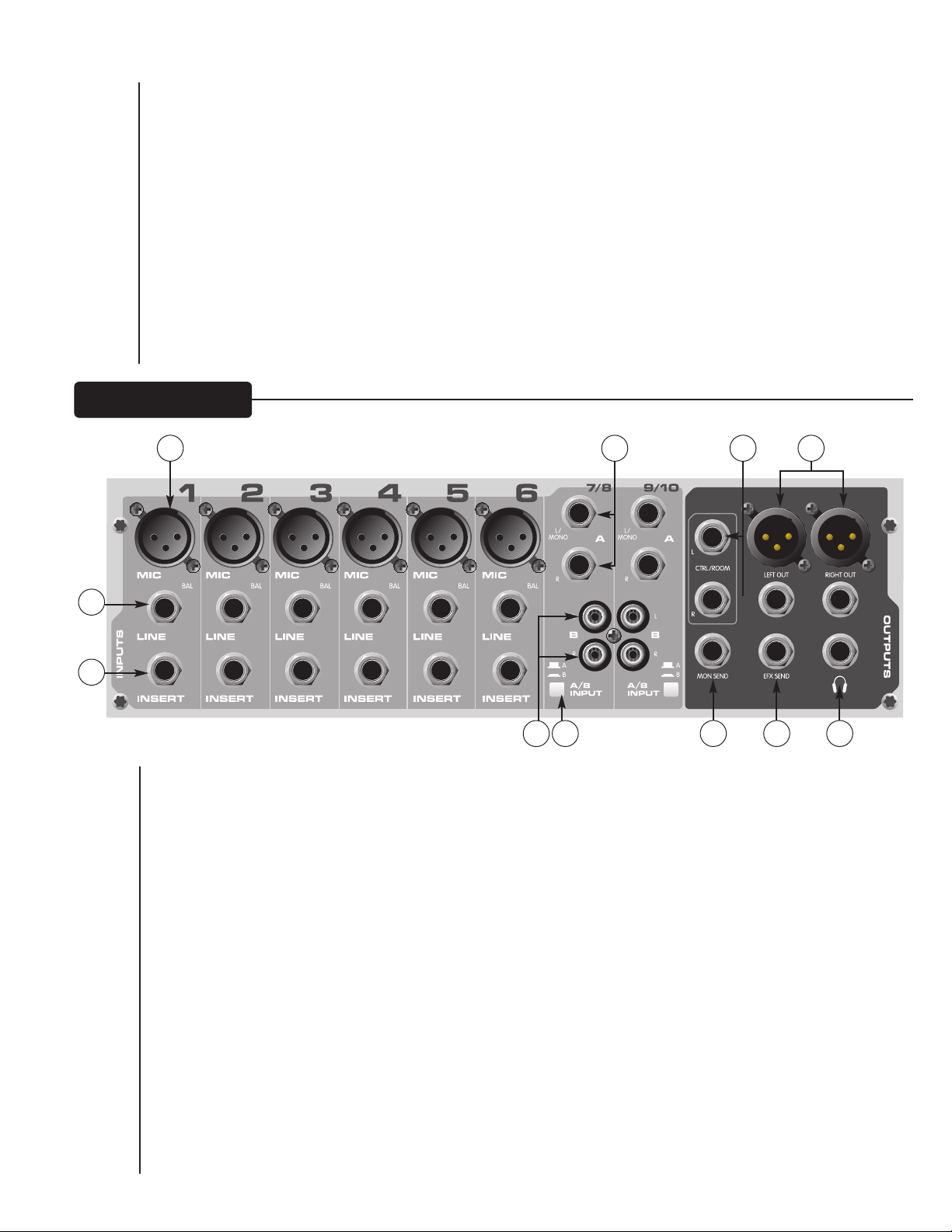
Tape To CTRL/HP (26)
Mit diesem Schalter wird Tape Return den Control-Room- (38) und Kopfhörerausgängen (40) zur Überwachung ohne
Latenzzeit zugefügt.
Tape to Mix (27)
Ist dieser Schalter aktiviert, wird das Signal von den Tape-Eingängen (13) zu den Main-Ausgängen (39) geleitet.
Contour-Schalter (28)
Ist dieser Schalter aktiviert, wird das Signal durch Hinzufügen von Bässen und Höhen verstärkt. Dies ist bei
geringeren Lautstärken für Tonband- bzw. CD-Playback besonders wirksam.
Master Level Faders (29)
Die Master-Fader regeln die Pegel, die an die Main-Left/Right-Ausgänge gesendet werden. Die besten
Ergebnisse werden erzielt, wenn diese Regler um die Position 0 eingestellt werden.
RR ÜÜ CC KK SS EE II TT EE
31
32
30
34
35
33
38
36 37
39
40
Mic- (XLR-) Eingänge (30)
Symmetrierte XLR-Eingänge, die für ein Mikrofon oder eine andere niederohmige Quelle optimiert wurden.
Stift 2 ist der positive Eingang. Auf Grund der Vielzahl an möglichen Gain-Einstellungen können Signalpegel von
bis zu +14 dBu erreicht werden.
Line-Eingänge (6,3 mm) (31)
Dies ist ein symmetrierter 6,3-mm-(TRS)-Klinkeneingang mit einer Impedanz von 10 kOhm. Die Spitze ist der
positive Eingang und wird für unsymmetrierte Eingänge verwendet. Sein Gain liegt 20 dB unter dem des XLREingangs, und er hat keine Phantomspeisung. Die Mic- und Line-Eingänge dürfen nicht gleichzeitig verwendet
werden.
Insert (32)
6,3-mm-Klinkenstecker, der das Einschleifen externer Signalprozessoren in den Kanalsignalweg ermöglicht.
Spitze = Send, Ring = Return, Masse = Erde.
Stereo-Eingänge (6,3 mm) (33)
Diese unsymmetrierten 6,3-mm-Eingänge dienen als Stereo-Line-Eingang mit beiden Klinken oder als MonoEingang, wenn der Anschluss nur an den Left/Mono-Eingang erfolgt. Damit diese Klinken aktiv sind, muss der
A/B-Eingangswahlschalter auf „A“ stehen.
32
Page 33

Cinch-Eingänge (34)
Diese Cinch-Eingänge fungieren als Stereo-Line-Eingänge. Damit diese Klinken aktiv sind, muss der A/BEingangswahlschalter auf „B“ stehen.
A/B-Schalter (35)
Der A/B-Eingangswahlschalter erweitert die Fähigkeiten des PV 10- bzw. PV 14-Mischpults, da zwei Stereoquellen
an jeden Stereo-Line-Eingang angeschlossen werden können. Anstatt sie nochmals anschließen zu müssen, kann mit
dem Schalter ausgewählt werden, welche Eingangsklinken aktiv sind.
MON Send (36)
Der MON Send verfügt über eine symmetrierte 6,3-mm-Klinke in der Master-Stufe. Dieser Ausgang kann mit
symmetrierten Klinkensteckern (Spitze, Ring, Masse) oder unsymmetrierten Klinkensteckern (Spitze, Masse)
verwendet werden. Der MON-Mix wird durch die Stärke des Signals, das an den MON-Bus in jedem Kanal gesendet
wird, und durch den Monitor-Master-Regler festgelegt.
EFX Send (37)
Der EFX Send verfügt über eine symmetrierte 6,3-mm-Klinke in der Master-Stufe. Diese Ausgänge können mit
symmetrierten Klinkensteckern (Spitze, Ring, Masse) oder unsymmetrierten Klinkensteckern (Spitze, Masse)
verwendet werden. Der EFX-Mix wird durch die Stärke des Signals, das an den EFX-Bus in jedem Kanal gesendet
wird, und durch den EFX-Master-Regler festgelegt.
Control-Room-Ausgänge (38)
Die Control-Room-Ausgänge verfügen über zwei symmetrierte 6,3-mm-Klinken. Diese Ausgänge können mit
symmetrierten Klinkensteckern (Spitze, Ring, Masse) oder unsymmetrierten Klinkensteckern (Spitze, Masse)
verwendet werden. Der Control-Room-Ausgangspegel wird mit dem Headphone-Pegelregler (21) eingestellt.
Left/Right Outputs (39)
The left/right Outputs feature two 1⁄4
be used with Tip‚ Ring, Sleeve (TRS) balanced or Tip, Sleeve (TS) unbalanced connectors. The output level is set by
the Master Level faders (29). Both outputs can be used simultaneously.
" TRS Z-balanced jacks and two fully balanced XLR outputs. The
1
⁄4
" outputs can
Kopfhörerausgang (40)
Der Kopfhörerausgang ist eine 6,3-mm-Klinke (Spitze = links, Ring = rechts, Masse = Erde). Das an diesen Ausgang
gesendete Signal ist in der Regel der Left/Right-Mix. Ist der Tape-to-Control-Room-Schalter aktiviert, wird das Tape-
Eingangssignal dem Left/Right-Mix zugefügt und kann über die Kopfhörer überwacht werden.
33
Page 34
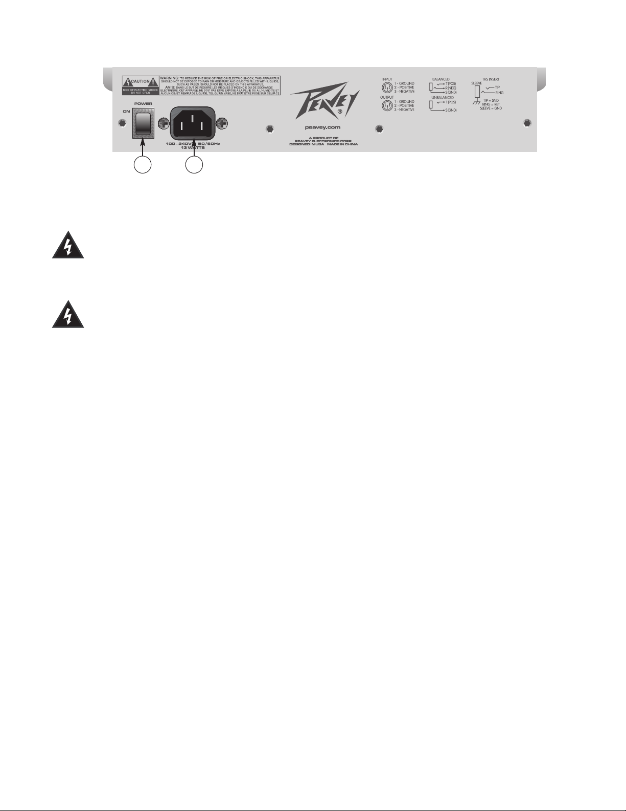
41
42
Power-Schalter (41)
Durch Drücken dieses Schalters wird das Gerät mit Netzstrom versorgt.
Achtung: Der Netzschalter dieses Geräts unterbricht nur eine Seite der Leitung. Daher kann das
Mischpult gefährliche Energie abgeben, selbst wenn der Netzschalter auf OFF steht.
Abziehbares Netzkabel (42)
In diese Steckdose wird das beiliegende IEC-Netzkabel gesteckt, über das das Gerät mit Wechselstrom
versorgt wird. Schließen Sie das Netzkabel an diesen Stecker und an eine korrekt geerdete
Wechselstromversorgung an. Wird eine ungeeignete Netzspannung verwendet, kann dies das Gerät
beschädigen (siehe Spannungsangaben am Gerät). Der Erdungsstift am Stecker des Netzkabels darf auf keinen
Fall entfernt oder abgeschnitten werden. Das Mischpult wird mit einem Netzkabel geliefert, das die korrekten
Werte aufweist. Sollte das Kabel verloren gehen oder beschädigt werden, muss es durch ein Kabel mit den
korrekten Werten ersetzt werden.
HINWEIS: NUR FÜR GROSSBRITANNIEN
Sollte die Farbe der Drähte in der Netzleitung dieses Geräts nicht mit den farbigen Markierungen für die
Klemmen in Ihrem Stecker übereinstimmen, gehen Sie folgendermaßen vor: (1) Der grün-gelbe Draht muss an
die mit E oder durch das Symbol für Erde markierte oder grüne bzw. grün-gelbe Klemme angeschlossen werden.
(2) Der blaue Draht muss an die mit N markierte oder schwarze Klemme angeschlossen werden. (3) Der
braune Draht muss an die mit L markierte oder rote Klemme angeschlossen werden.
34
Page 35
PEAVEY ELECTRONICS CORPORATION LIMITED WARRANTY
Effective Date: July 1, 1998
WWhhaatt TThhiiss WWaarrrraannttyy CCoovveerrss
Your Peavey Warranty covers defects in material and workmanship in Peavey products purchased and serviced in the U.S.A. and Canada.
WWhhaatt TThhiiss WWaarrrraannttyy DDooeess NNoott CCoovveerr
The Warranty does not cover: (1) damage caused by accident, misuse, abuse, improper installation or operation, rental, product modification or neglect; (2) damage occurring during shipment; (3) damage caused by repair or service performed by persons not authorized by Peavey; (4) products on which the serial number
has been altered, defaced or removed; (5) products not purchased from an Authorized Peavey Dealer.
WWhhoo TThhiiss WWaarrrraannttyy PPrrootteeccttss
This Warranty protects only the original retail purchaser of the product.
HHooww L
Loonngg TThhiiss WWaarrrraannttyy LLaassttss
The Warranty begins on the date of purchase by the original retail purchaser. The duration of the Warranty is as follows:
Product Category Duration
Guitars/Basses, Amplifiers, Pre-Amplifiers, Mixers, Electronic
Crossovers and Equalizers 2 years *(+ 3 years)
Drums 2 years *(+ 1 year)
Enclosures 3 years *(+ 2 years)
Digital Effect Devices and Keyboard and MIDI Controllers 1 year *(+ 1 year)
Microphones 2 years
Speaker Components (incl. speakers, baskets, drivers,
diaphragm replacement kits and passive crossovers)
and all Accessories 1 year
Tubes and Meters 90 days
[*Denotes additional warranty period applicable if optional Warranty Registration Card is completed and returned to Peavey by original retail purchaser within 90 days of purchase.]
WWhhaatt PPeeaavveeyy WWiillll DDoo
We will repair or replace (at Peavey's discretion) products covered by warranty at no charge for labor or materials. If the product or component must be shipped to
Peavey for warranty service, the consumer must pay initial shipping charges. If the repairs are covered by warranty, Peavey will pay the return shipping charges.
HHooww TToo GGeett WWaarrrraannttyy SSeerrvviiccee
((11))
Take the defective item and your sales receipt or other proof of date of purchase to your Authorized Peavey Dealer or Authorized Peavey Service Center.
OR
((22))
Ship the defective item, prepaid, to Peavey Electronics Corporation, International Service Center, 412 Highway 11 & 80 East, Meridian, MS 39301 or Peavey
Canada Ltd., 95 Shields Court, Markham, Ontario, Canada L3R 9T5. Include a detailed description of the problem, together with a copy of your sales receipt or
other proof of date of purchase as evidence of warranty coverage. Also provide a complete return address.
LLiimmiittaattiioonn ooff IImmpplliieedd WWaarrrraannttiieess
ANY IMPLIED WARRANTIES, INCLUDING WARRANTIES OF MERCHANTABILITY AND FITNESS FOR A PARTICULAR PURPOSE, ARE LIMITED IN DURATION T
LENGTH OF THIS WARRANTY.
Some states do not allow limitations on how long an implied warranty lasts, so the above limitation may not apply to you.
EExxcclluussiioonnss ooff DDaammaaggeess
PEAVEY'S LIABILITY FOR ANY DEFECTIVE PRODUCT IS LIMITED TO THE REPAIR OR REPLACEMENT OF THE PRODUCT, AT PEAVEY'S OPTION. IF WE ELECT TO
REPLACE THE PRODUCT, THE REPLACEMENT MAY BE A RECONDITIONED UNIT. PEAVEY SHALL NOT BE LIABLE FOR DAMAGES BASED ON INCONVENIENCE, LOSS OF
USE, LOST PROFITS, LOST SAVINGS, DAMAGE TO ANY OTHER EQUIPMENT OR OTHER ITEMS ATTHE SITE OF USE, OR ANY OTHER DAMAGES WHETHER INCIDENTAL,
CONSEQUENTIAL OR OTHERWISE, EVEN IF PEAVEY HAS BEEN ADVISED OF THE POSSIBILITY OF SUCH DAMAGES.
Some states do not allow the exclusion or limitation of incidental or consequential damages, so the above limitation or exclusion may not apply to you.
O THE
This Warranty gives you specific legal rights, and you may also have other rights which vary from state to state.
If you have any questions about this warranty or service received or if you need assistance in locating an Authorized Service Center, please contact the Peavey
International Service Center at (601) 483-5365 / Peavey Canada Ltd. at (905) 475-2578.
Features and specifications subject to change without notice.
35
Page 36

Features and specifications subject to change without notice.
Peavey Electronics Corporation • 711 A Street • Meridian • MS • 39301
(601) 483-5365 • FAX (601) 486-1278 • www.peavey.com
EX 000002
©2004 Printed in the U.S.A. 10/04
 Loading...