

Page 1
PV® Series Ampliers
Operating
Manual
20
23
16
6
16
6
16
6
26
THERMAL PROTECT
29
TM TM
PWR
SIG
DDT
32
20
23
26
29
PWR
32
20
23
26
29
PWR
32
DDT
THERMAL PROTECT
TM TM
SIG
DDT
DDT
THERMAL PROTECT
TM TM
SIG
DDT
DDT
SIG PWR
SIG PWR
SIG PWR
20 23
16
6
16
6
16
6
26
29
32
20 23
26
29
32
20 23
26
29
32
www.peavey.com
Page 2

ENGLISH
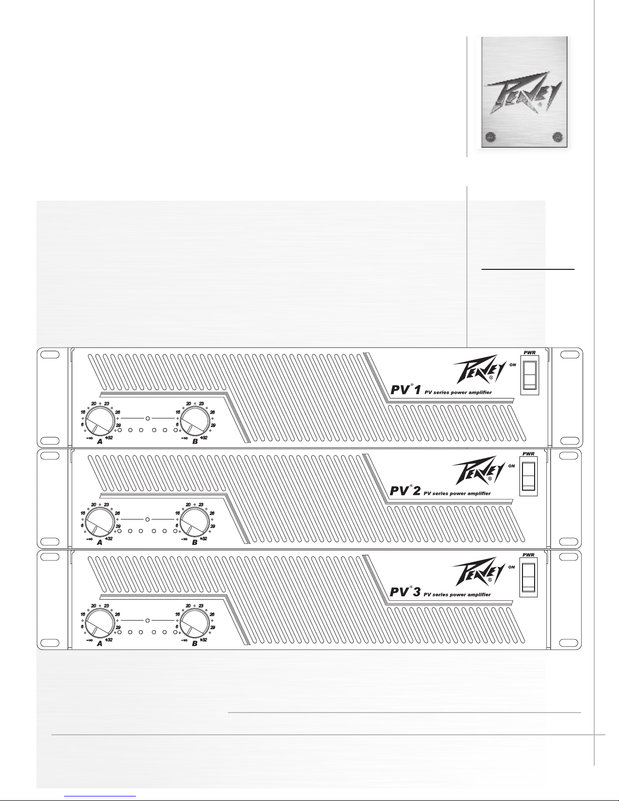
PV® SERIES PROFESSIONAL STEREO POWER AMPLIFIER
INTRODUCTION
Congratulations! You have just purchased one of the world’s finest professional power amplifiers. The PV amplifier
features a two-way crossover and sub-sonic (low-cut) filter for each channel. Crossover frequencies are fixed at 150 Hz,
allowing subwoofers to be driven at extremely high sound pressure levels, and the filters cut at 40 Hz to prevent low-end
rumble. Using proven technology gained through years of amplifier design, this unit takes advantage of rugged TO-3P
output devices mounted on massive aluminum extrusions and dissipates heat via an extremely quiet and effective
two-speed fan. PV amplifiers are designed to operate at line voltages as low as 50% of nominal, employing mammoth
toroidal power transformers and offering impressive specifications and features not found on similarly priced competitive
units. This amp is designed to drive a 2-Ohm load per channel, thus achieving awesome performance levels into 4
Ohms in BRIDGE mode. PV amplifiers are ruggedly constructed, rack-mountable pieces of gear with superb patching
capability, allowing superior flexibility in application. Front panel features include calibrated, detented gain (dB) controls
and LED indicators for power (PWR), signal presence (SIG), Thermal Protection indicator, and DDT™ activation on each
channel, as well as a rocker mains POWER switch. The back panel contains an IEC connector, line voltage selector
switch, dual primary fuses, and the critical cooling fan opening. This opening should have an adequate supply of cool air
and should never be blocked or restricted. Also on the back panel are the input and output sections, including an input
barrier strip for permanent installations. Each channel input section includes a combo XLR / TRS phone jack connector,
THRU/LOW out and HIGH out TRS jacks, and activation switches for the LOW CUT filter and crossover (150 Hz
XOVER). Channel output sections feature dual shock-proof binding posts and four-conductor twist lock connectors. An
additional four-conductor twist lock connector allows BRIDGE mode output.
UNPACKING
Inspect the amplifier during unpacking. If any damage is found, notify your dealer immediately. Be sure to save the
carton and all packing materials. Should you ever need to ship the unit back to Peavey Electronics, one of its service
centers, or the dealer; use only the original factory packing.
INSTALLATION
PV professional power amplifiers are designed for durability in commercial installations and provide the quality
performance required in studio and home applications. They are two-rack-space units of 16" (406 mm) depth designed
to mount in a standard 19" rack. Rear mounting ears are provided for additional support. The minimum rack depth
required from the mounting surface is 17" (432 mm) to allow adequate connector clearance.
BASIC SETUP
Before mounting, make sure the line voltage selector is set to the correct voltage (page 9).
Rack mount the amplifier in the location where it is to be used, remembering to allow for adequate access and cooling
space. Make all the connections to the desired INPUT connectors on the desired channel. Select the proper mode
configuration (STEREO or BRIDGE). Connect speakers to the desired OUTPUT connectors.
Make sure the load impedance is greater than 2 ohms per channel (4 ohms bridged) to prevent the amplifier from
shutting down. With the POWER switch OFF, connect the IEC cord (7) to the amplifier and then to an outlet of the
proper voltage. With both channel gain controls turned fully counterclockwise, turn the Power switch on, and raise the
gain controls to achieve the desired sound level. Please carefully review this manual to learn about all the features and
designed-in behaviors of your new PV® Series power amplifier!
7
Page 3
THERMAL PROTECT
PWR
6
16
20
23
26
29
32
6
16
20 23
26
29
32
SIG
DDT
TM TM
DDT
SIG PWR
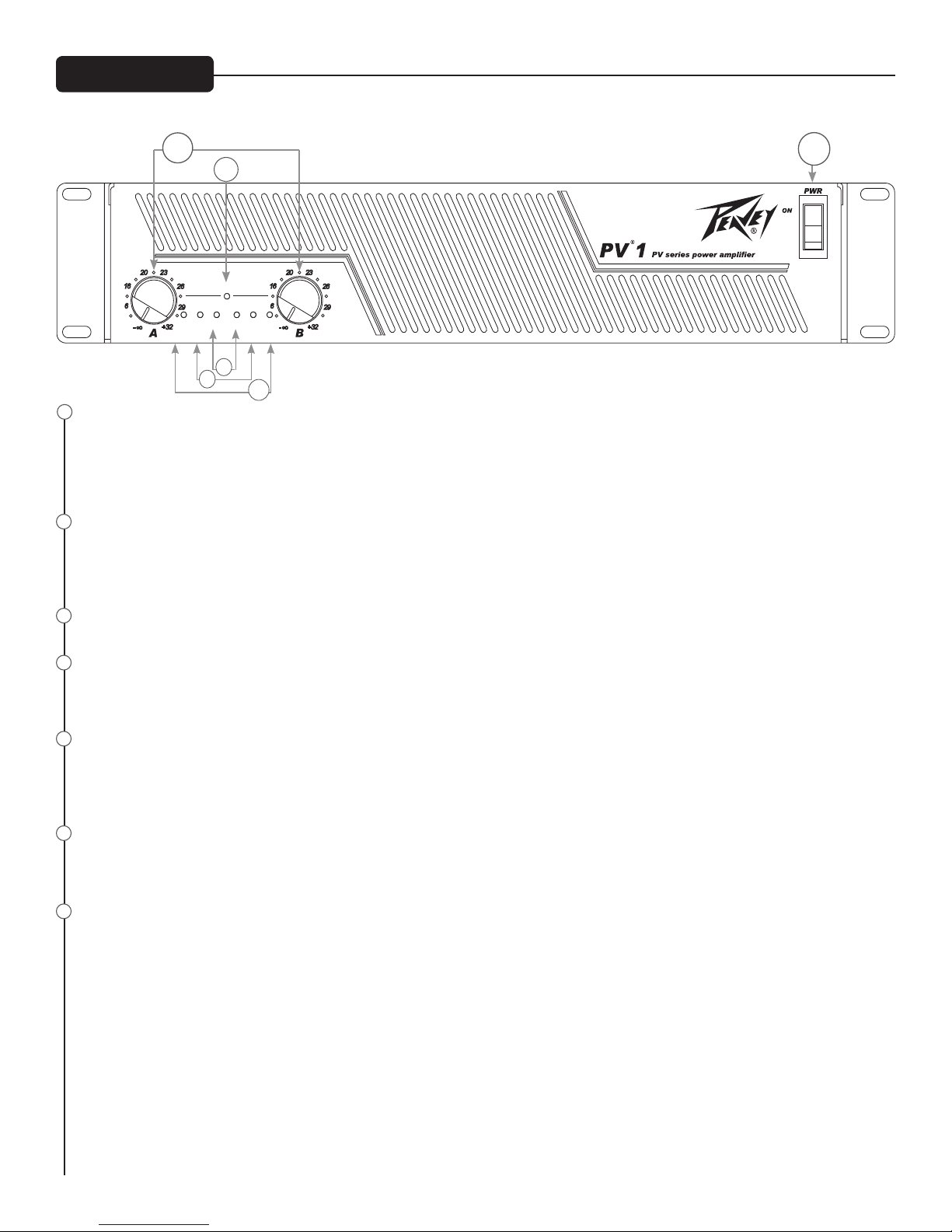
Front Panel
1
INPUT GAIN (dB)
1
5
4
3
2
6
These controls are used to adjust the input gain of each channel. They determine how “loud” each channel of the power amplifier
will sound for a given input signal level. Maximum input gain is achieved at the fully clockwise setting (+32 dB, 40 X), and this
setting yields maximum mixer/system headroom. A setting of less than fully clockwise will yield lower system noise at the
expense of mixer/system headroom. Turning the control fully counterclockwise is the “off” setting (-∞). It is always a good idea to
power up any new installation at this setting to protect the system loudspeakers.
2
POWER LEDS (PWR)
These indicators illuminate when the AC mains power is being supplied to the amp and both channels are operational. If either
channel experiences fault conditions, exceeds safe operating temperature limits, or if the mains circuit breaker trips; both channel
power LEDs will be dark, indicating “shutdown”. If the BRIDGE mode is selected, the PWR indicator on channel B will remain
dark as a positive indication of this mode selection.
3
SIGNAL ACTIVITY LEDS (SIG)
These indicators illuminate when the associated channel output signal level exceeds 1 V RMS.
4
DDT™ ACTIVE LEDS
These indicators illuminate when DDT compression is taking place in the associated channel. If the rear panel DDT switch is
depressed, then DDT is defeated and these LEDs indicate clipping is occurring in the corresponding channel. The Peavey DDT
compression system will be covered in greater detail later in this manual.
5
Thermal Protect LED
This indicator illuminates when the thermal sensor on either heatsink reaches approximately 90 degrees C, at which point, the
amplifiers are muted while the fan remains on high speed. If this happens repeatedly, either reduce the load on the amplifier
(detach one of the speakers), or supply additional cooling to the amplifier, such as a fan. When rack mounting, it is helpful to
leave 1 RU open above and below the amplifier to prevent heat buildup from adjacent units.
6
POWER SWITCH
This heavy-duty, rocker-type switch turns on the mains power to the amplifier. When the mains power is applied, there is a delay
in activation of the unit. This reduces/eliminates the turn-on transients associated with the system equipment connected to the
amplifier and protects loudspeakers.
7
DUAL PRIMARY FUSE
In order to accommodate line voltage switching, the power transformer is designed with two primaries that can be placed in
series or parallel by means of the line voltage selector switch. Each primary is individually fused, so there is no need to change
fuse values when a different line voltage is selected. It is important to use the fuse values specified on the rear panel. The fuses
are provided to limit current to the associated transformer primary winding, and protect it from overheating and possible
destruction due to fault conditions in the unit. The trip current values have been carefully chosen to allow reasonable continuous
power output performance, while still protecting the power transformer. These fuses should not open unless there is a fault in the
amplifier circuitry that causes excessive mains current draw. However, abnormal conditions such as a short circuit on either or
both channels, or continuous operation at overload or clipping (especially into 2-ohm loads per channel or 4-ohm bridge load)
can cause the fuses to open. If this occurs, UNPLUG from the AC POWER source before replacing the fuses, after waiting a brief
period of time to allow the unit to cool down. Efforts should be made to correct the cause of the overload, first by disconnecting
one output at a time, and then one speaker at a time until the bad cable or damaged speaker is isolated. If the fuses open
instantly each time you attempt to turn the unit on, it should be taken to a qualified Peavey Service Center for repair.
8
Page 4

INPUTS
CHANNEL
A
CHANNEL
A
CHANNEL
B
CHANNEL
B
LINE OUTS
BRIDGE
BRIDGE
SPEAKER OUTPUTS
MADE IN CHINA
230V
T 15AL
250V
115V
MOUNT IN RACK ONLY
INSTALLER SUR SUPPORT
DE MONTAGE SEULEMENT
BRIDGE
+
++
_
_ _
DDT
TM
STEREO
BRIDGE
A
B
+
-
+
-
40 Hz
GND
40 Hz
150 Hz
X-OVER
150 Hz
X-OVER
HIGH
OUT
LOW
OUT
HIGH
OUT
LOW
OUT
THRU
THRU
ENABLE
DEFEAT
Rear Panel
7
8
8
IEC MAINS CONNECTOR
9
This is a standard IEC power connector. An AC mains cord having the appropriate AC plug and ratings for the intended
operating voltage is included in the carton.
U.S. DOMESTIC AC MAINS CORD
The mains cord supplied with the unit is a heavy-duty, three-conductor type with a conventional 120 VAC plug with ground pin.
It should be connected to an independent circuit capable of continuously supporting at least 15 amps. This is particularly critical
for sustained high-power applications. If the outlet used does not have a ground pin, a suitable grounding adapter should be
used and the third wire grounded properly.
Never break off the ground pin on any equipment. It is provided for your safety.
The use of extension cords should be avoided but, if necessary, always use a three-wire type with at least a #14 AWG
wire size. The use of lighter wire will severely limit the power capability of this amplifier. Always use a qualified
electrician to install any new electrical equipment. To prevent the risk of shock or fire hazard, always be sure that the amplifier
and all associated equipment is properly grounded.
NOTE: FOR UK ONLY
If the colors of the wires in the mains lead of this unit do not correspond with the colored markings identifying the terminals in
your plug, proceed as follows: (1) The wire that is colored green and yellow must be connected to the terminal that is marked
by the letter E, the earth symbol, colored green, or colored green and yellow. (2) The wire that is colored blue must be
connected to the terminal that is marked with the letter N or the color black. (3) The wire that is colored brown must be
connected to the terminal that is marked with the letter L or the color red.
9
LINE VOLTAGE SELECTOR SWITCH
The PV series power transformer is designed with two primaries that can be placed in series or parallel by means of the line
voltage selector switch. It is accessible by loosening one screw and rotating the transparent guard out of the way. Please be
sure this is set to the proper voltage for your area before turning the amplifier on for the first time.
10
BINDING POST OUTPUTS
Shockproof binding post speaker outputs are provided on the PV® amplifier. For each channel, the outputs are in parallel and
the speaker connection cables can be terminated with banana plugs or stripped wires for use in the binding post terminals, or
can be connected using the twist lock outputs (11). For sustained high-power applications, either outputs can be used;
however, exercise care to assure the correct speaker polarity. The red binding posts are the signal outputs from each channel,
and the black binding posts are chassis ground. The red binding post should be connected to the positive inputs of the
associated loudspeakers. For BRIDGE mode operation, only the red binding posts are used, and the loudspeaker load is
connected between the two red posts, with CH A having positive polarity and CH B having negative polarity.
WARNING. Regardless of what connections are used, the minimum parallel speaker load should always be limited to
2 Ohms per channel, or 4 Ohms when in BRIDGE mode. Operation at loads of 4 Ohms per channel, or 8 Ohms
BRIDGE mode, is more desirable for sustained operation applications because the amplifier will run much cooler with
this load. Operation above 4 Ohms per channel and even open-circuit conditions can always be considered safe, but sustained
operation at loads below 2 Ohms could result in temporary amplifier shut down due to the thermal limit circuitry.
11
TWIST LOCK OUTPUTS
PV® amplifiers utilize three 4-conductor twist lock connectors, one for each channel and one for BRIDGE mode. Please refer
to the BRIDGE MODE section of this manual before attempting to use this mode. For each channel twist lock, the same
impedance rules apply as with the binding posts. Internally, all the twist locks are wired in the “high current” configuration, with
11
10
12
19
17
16
15
13
20
13
9
14
18
10
Page 5

pins 1+ and 2+ in parallel, and pins 1- and 2- in parallel. For the CHANNEL A and CHANNEL B twist locks, the respective channel
output appears on pins 1+ and 2+. Pins 1- and 2- are chassis ground. For the BRIDGE twist lock, CHANNEL A appears on pins 1+
and 2+, and CHANNEL B appears on pins 1- and 2-. Always check the twist lock connector wiring carefully before using.
12
MODE SWITCH
This switch is best changed when the amplifier is off. It is used to select STEREO or BRIDGE mode operation. It is a recessed
push-push type, requiring a small tool to activate. The IN position is BRIDGE mode; the OUT position is STEREO mode. Exercise
care when selecting the BRIDGE mode. Accidental selection of this mode could damage loudspeakers, particularly in bi-amped
systems. Amplifier BRIDGE mode theory will be covered later in this manual.
13
DDT™ (DISTORTION DETECTION TECHNIQUE) SWITCH
This switch is used to enable or defeat the DDT compressor circuitry. It is also a recessed push-push type, requiring a small tool to
activate. The IN position is DEFEAT; the OUT position is ENABLE. Normally, the DDT function should be enabled to minimize
clipping. With this feature defeated, a severe overload could cause the mains circuit breaker to trip. The Peavey DDT compression
system will be covered in greater detail later in this manual.
14
FAN GRILLE
A two-speed DC fan supplies cool air to the amplifier. THIS INTAKE SHOULD NEVER BE BLOCKED! The fan switches to
high speed automatically when the unit requires additional cooling. At idle and cool, the fan runs at low speed. The fan should never
stop unless the amplifier is switched OFF or the AC mains power source is interrupted, or the thermal breaker in the transformer
has tripped due to excess heating. The thermal breaker in the transformer is self-resetting once the excess heat has dissipated.
15
INPUT BARRIER STRIP
A barrier strip is provided for input connections using bare wire or spade lug connections. PV amplifiers employ low-noise,
electronically balanced input circuitry. This circuitry offers a very wide dynamic range capable of handling virtually any input signal
level, while providing excellent common mode rejection to minimize hum and reduce interference. This strip accepts balanced and
unbalanced audio signals. The "+" and "-" terminals are the positive and negative inputs to the respective channels. The GND
terminal is the common ground to both channel inputs. For use with an unbalanced source, connect the "-" input terminal of the
channel to ground with a jumper. If the "-" input is left floating, a 6 dB loss in channel gain will result and the floating input terminal
may pick up outside noise.
16
COMBO INPUT CONNECTOR
The combo connector offers both female XLR and 1/4" phone jack balanced inputs for each channel. The XLR is wired with pin 1 as
ground, pin 2 positive input, and pin 3 negative input. The 1/4" phone jack is a tip/ring/sleeve (3-conductor) type, with the tip being
positive input, the ring negative input, and the sleeve ground. It is important to realize that the XLR, 1/4" jack, and barrier strip
inputs are all in parallel; therefore a balanced input to the associated channel can be accomplished using a male XLR, a
3-conductor phone jack, or bare wires connected to the barrier strip.
As an alternative, the 1/4" input can also be used with a regular tip/sleeve (2-conductor) type plug commonly found on
single-conductor shielded patch cords. In this case, the input becomes unbalanced, with the tip as positive input, and the sleeve
ground (the ring being grounded by the sleeve of the plug).
17
/40 Hz SWITCH
This switch is used to activate the high-pass filter for the corresponding channel. It is again a push-push type switch, requiring a
small tool to activate. The IN position routes the input signals through the 40 Hz high-pass filter, while the OUT position bypasses
the filter. This filter cuts extremely low frequencies, protecting speakers from over-excursion. The filter low-frequency rolloff is 12 dB
per octave. The high-pass filter for each channel will function independently of the crossover function to be discussed next.
18
CROSSOVER SWITCH (150 Hz XOVER)
This switch is used to activate the 150 Hz crossover for the corresponding channel. It is also a push-push type switch and requires
a small tool to activate. The PV® offers two 150 Hz crossovers. These are designed for use when a subwoofer is added to the
system.
With the switch IN, the input signals are routed through the crossover, and the low frequencies are automatically sent to the
corresponding channel. At the same time, the high frequencies are sent to the HIGH OUT (20) jack and must then be patched to an
INPUT of the other channel of this amplifier or to another amplifier input to complete the bi-amped system. Additionally, the low
frequencies are sent to the THRU/LOW OUT (19) jack, and can be patched to other amplifier inputs to permit even larger systems.
With the switch OUT the crossover is defeated, and the input signal is routed to the line level THRU output jack. The crossover
frequency is fixed at 150 Hz and cannot be changed. The crossover configuration is a 4-pole Linkwitz-Riley approximation.
19
THRU/LOW OUT JACKS
As per previous crossover discussion, this 1/4" jack supplies low-frequency out signals from the activated crossover for patching to
additional power amplifier inputs, providing added flexibility in larger bi-amped systems. When the crossover function is not
activated, this jack converts to a THRU function, where the output of the electronically balanced input circuitry is supplied to this
jack. The THRU function provides the means to patch a full range input signal to the other input of this amplifier (parallel mode), or
to other amp inputs in the same rack. This function allows one balanced mixer feed to be connected to the amp via the desired
balanced input connector (XLR, 1/4", Barrier), and then further distributed locally. Regardless of the crossover switch position, this
1/4" jack provides an impedance balanced (TRS) output. Although 2-conductor balanced (TRS) cables will provide better noise
immunity, single conductor shielded (tip/sleeve) cables can also be used.
10
Page 6

20
HIGH OUT JACKS
Again, as per previous crossover discussion, this 1/4" jack supplies high frequency out signals from the activated crossover for
patching to this amplifier and/or additional power amplifier inputs. Unlike the low-frequency crossover output, that is automatically
routed to the associated channel, the high-frequency output signal must be patched to some suitable input in order to complete the
bi-amped system. This 1/4" jack provides an impedance balanced (TRS) output. Although 2-conductor balanced (TRS) cables will
provide better noise immunity, single conductor shielded (tip/sleeve) cables can also be used.
INDUSTRIAL AND COMMERCIAL INSTALLATIONS
For commercial and other installations where sustained high-power operation is required, the amplifiers should be mounted in a
standard 19" rack. It is a good idea to leave a rack space between each amplifier in the stack to prevent heat builup between units
and induced hum from transformer magnetic fields. Regardless, an adequate cool air supply must be provided for the amplifier
when rack mounted. The internal fan must have a source of air that is not preheated by other equipment. The amplifier will start up
in low speed fan operation and will normally stay at low speed unless sustained high-power operating levels occur. Then, as
temperatures in the amplifier heat sinks increase, thermal-sensing circuitry will cause high-speed operation to occur. Depending
upon signal conditions and amp loading, high-speed fan operation may continue or the fan may cycle continuously between high
and low. This behavior is by design. If cooling is inadequate, however, the amplifier thermal-sensing system may cause temporary
shut down of the unit, indicated by the front panel THERMAL PROTECT LED. Inadequate cooling may be due to preheated air,
reduced air flow resulting from blockage of inlet/outlet ports, amplifier overload, or short circuit conditions. Depending upon the
available cooling air, operation should be restored relatively quickly, and the power LEDs on both channels will again be
illuminated. In any event, action should be taken to correct the cause of the thermal shutdown. If the amplifier is not severely
overloaded or shorted and air flow is normal in and out of the amplifier, then steps should be taken to provide a cooler
environment for all the amplifiers.
As a general rule, most home and studio requirements will never cause high-speed fan operation. High-speed operation may
indicate that you have not taken the necessary steps to provide adequate cooling. The PV® Series should never be operated in a
fully enclosed cabinet.
BRIDGE MODE
When a 2-channel amplifier is operated in the Bridge mode, it is converted into a single-channel unit with a power rating equal to
the sum of the power rating for each channel, at a load of twice that of the single-channel rating. For example, the PV 2 is rated at
750 Watts RMS per channel into 2 Ohms. The Bridge rating is 1500 Watts RMS into 4 Ohms (minimum load). Bridge mode
operation is accomplished by placing the MODE switch in the BRIDGE position, using only the BRIDGE twist lock connector or the
red binding posts for the output, and using the CHANNEL A input. All CHANNEL B input functions are defeated and serve no
purpose now. Bridge mode operation can be used to drive sound distribution systems in very large public address applications.
Another common use for the Bridge mode is in subwoofer applications where very high power levels are required to reproduce
extremely low frequencies with adequate headroom. Such enclosures usually contain 2 or 4 loudspeakers to handle the power
levels involved. When using Bridge mode, the connected enclosure impedance must be 4 or 8 Ohms — never below 4 Ohms.
DDT™
Peavey’s patented DDT (Distortion Detection Technique) limiter circuit enables the sound technician to maximize the performance
of the amplifier/speaker combination by preventing the power amplifier from clipping. When the onset of clipping is detected, the
limiter engages to prevent damage to the loudpeakers and degradation of sound quality. For this reason, DDT should always be
enabled.
2 STAGE OVERCURRENT PROTECTION
Another unique feature of the PV® Series power amplifiers is a 2 stage overcurrent protection scheme. The first stage of
overcurrent protection uses a preset current threshold to prevent excessive current through the output devices when driving loads
of 2 ohms impedance or higher (4 ohms bridged). The second stage dramatically decreases the output of the amplifier if the
detected load impedance is one ohm or less, effectively muting the affected channel and keeping the output devices within their
Safe Operating Area.
When the second stage current limit engages, output will be extremely weak, and the front panel DDT LED will be glow steadily,
pulsing with the input signal, but dimly. The signal will not return until the overload is removed and the input level is reduced below
clipping. This behavior is by design. If this condition occurs, try reducing the input level so that the DDT LED only lights on the
loudest peaks. If it continues, inspect for shorted speaker cables, or a total load impedance of less than 2 ohms per channel / 4
ohms bridged.
11
Page 7

®
Specifications PV® 1 PV® 2 PV
RATED OUTPUT POWER @ 120V AC Line:
Stereo mode
4 Ohms, 1 kHz, 1% THD 410 W RMS/chan 630 W RMS/chan 1060 W RMS/chan
8 Ohms, 1 kHz, 1% THD 250 W RMS/chan 370 W RMS/chan 630 W RMS/chan
Bridge mode, mono
8 Ohms, 1 kHz, 1% THD 760 W RMS 1170 W RMS 1900 W RMS
HUM & NOISE:
"A" weighted, reference to rated power @ 8 ohms better than 88 dB
INPUT SENSITIVITY & IMPEDANCE:
@ rated output power, 4 ohms 1.08 V RMS / 2.87dBu 1.17 V RMS / 3.60dBu 1.26 V RMS / 4.23dBu
Balanced, TRS 1/4” phone jack 10 K Ohms per leg 10 K Ohms per leg 10 K Ohms per leg
Balanced, XLR (pin 2 positive) 10 K Ohms per leg 10 K Ohms per leg 10 K Ohms per leg
Overall system gain per channel 40X (+32 dB) 40X (+32 dB) 40X (+32 dB)
DISTORTION: (THD, typical value)
Stereo mode, both channels driven, 4 Ohms
20 Hz to 20 kHz, 10 dB below rated power Less than 0.1%
20 Hz to 2 kHz, at full rated power Less than 0.1%
FREQUENCY RESPONSE:
Stereo mode, both channels driven
+0, -2dB at 1 Watt 12Hz to 35 kHz
DAMPING FACTOR: (Typical value)
Stereo mode, both channels driven
8 Ohms, 20 Hz - 2 kHz > 250:1
3
POWER CONSUMPTION:
Stereo mode, both channels driven
@ 1/8 rated output power, 4 Ohms 450W 680W 600W
TOPOLOGY: Class AB Class AB
WEIGHT: 40 lbs (18.2 kg) 45 lbs (20.5 kg) 49 lbs (22.3 kg)
FEATURE SET: All Models (++ indicates each channel)
™
DDT
COOLING SYSTEM: Two-speed DC fan, air flow back to front
LOW CUT FILTER ++: -3 dB @ 40 Hz, 12 dB per octave
CROSSOVER ++: 150 Hz, 4-pole Linkwitz-Riley approximation
INPUTS ++: Electronic balanced; Barrier Strip, XLR, TRS 1/4" (6.3 mm)
CROSSOVER OUTPUTS ++: Low/Thru and High, TRS 1/4"Impedance balanced
AMPLIFIER OUTPUTS: Speakons for Chan A, Chan B and Bridge; Binding Posts
LED INDICATORS ++: Red, DDT/clipping; Yellow, signal; Red, Thermal Protect; Green, power
AMP PROTECTION: Full short circuit, open circuit; over-temp thermal; RF; stable into any load
LOAD PROTECTION: Turn on/off muting, DC (triac crowbar), low-cut filter
MAINS VOLTAGES AVAILABLE 100, 120, 230, 240 VAC, 50-60 Hz
DIMENSIONS: Height: 3.5” (8.9 cm), Width: 19" (48.3 cm), Depth: 15.5" (38.0 cm)
COMPRESSION ++: Automatic, switchable with LED indicator
Specifications subject to change without notice
Class G
12
Page 8

1
2
T
)
13
Page 9

14
Page 10

Logo referenced in Directive 2002/96/EC Annex IV
The bar is the symbol for marking of new waste and
13 August 2005
Warranty registration and information for U.S. customers available online at
Peavey Electronics Corporation 5022 Hartley Peavey Drive Meridian, MS 39305 (601) 483-5365 FAX (601) 486-1278
www.peavey.com
www.peavey.com/warranty
or use the QR tag below
Features and specications subject to change without notice.
(OJ(L)37/38,13.02.03 and defined in EN 50419: 2005
is applied only to equipment manufactured after
 Loading...