

Page 1
OPERATING INSTRUCTIONS
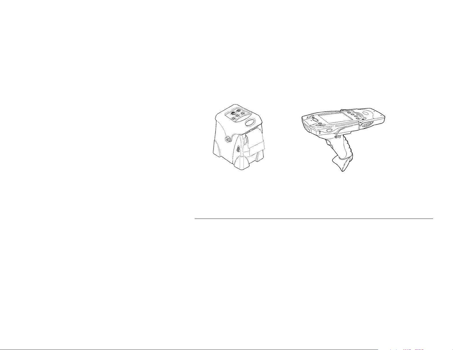
The Monarch® RF link with Trigger 7400™ unit is a dual-purpose device.
It is a radio frequency (RF) solution for cable-less communication
between a Symbol® PPT 2700 or 2800 terminal and a Monarch® Sierra
Sport™2 9460™ printer. It also has a trigger to initiate a bar code scans
easily.
The RF link device is under control of an application running on the
terminal. Your System Administrator must load the application before you
use it.
Getting Started
To start using the RF link device:
1. Insert a charged battery into the terminal. See the terminal’s
documentation for more information. The terminal’s battery also
powers the RF link device.
2. Insert the terminal into the RF link device. See “Inserting/Removing
the Terminal,” below.
3. Load supplies in the printer. See the printer’s documentation for
more information.
4. Link the RF link device with the printer. See “Linking the RF
Modules,” below.
TC7400TROI Rev. AB 4/02 ©2002 Paxar Corporation. All Rights Reserved.
Page 2
5. Run the application on the terminal. Your System Administrator will
instruct you how to do this.
NOTE: When using the RF link device, be sure to put your hand through
the safety strap before grabbing the handle.
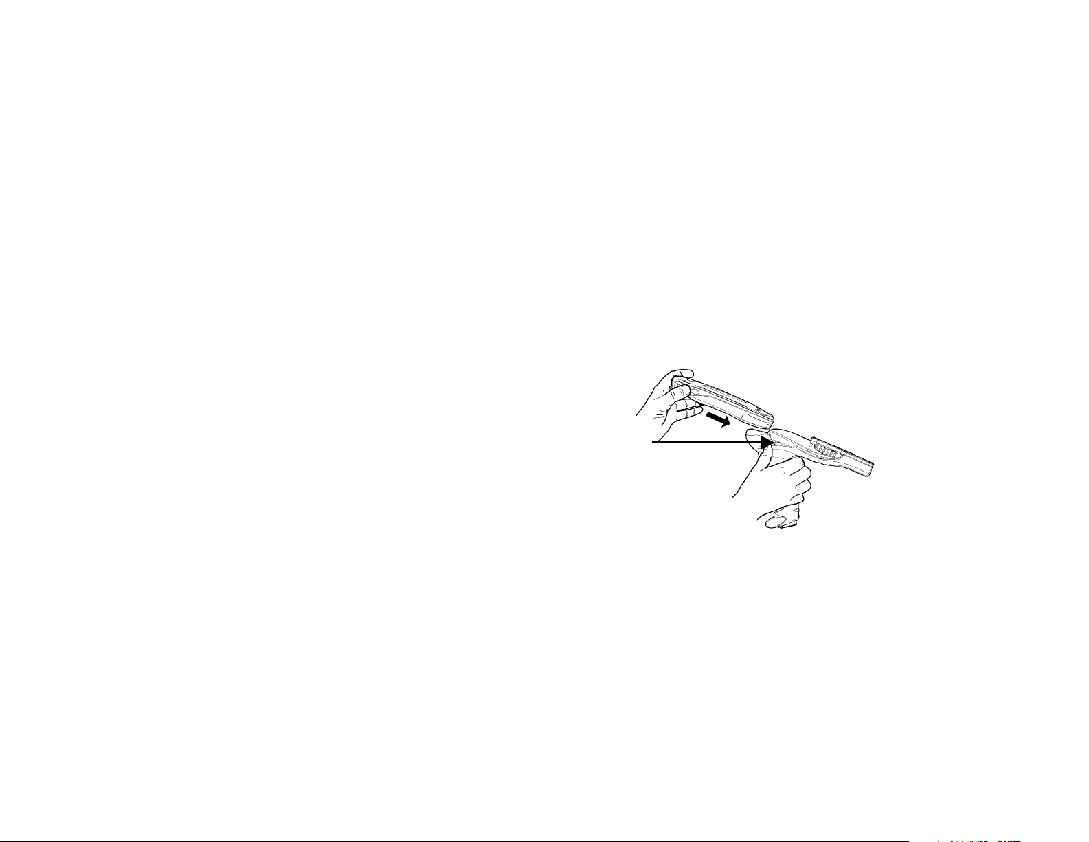
Inserting/Removing the Terminal
To insert the terminal into the RF link device:
1. Hold the RF link device upright horizontally with the trigger facing
the palm of your hand. Hold the terminal with the other hand,
oriented so that the word Symbol is at the bottom.
2. Push the insert/release lever with your thumb, and slide the terminal
(bottom first) into the RF link device’s slot, making sure the RF link
device’s connector goes into the terminal’s communication port. It
will click into place.
Insert/Release
Lever
To remove the terminal from the RF link device:
1. Hold the RF link device upright horizontally with the trigger facing
the palm of your hand.
2. Push the insert/release lever with your thumb, and pull the terminal
out of the RF link device.
2 Operating Instructions
Page 3
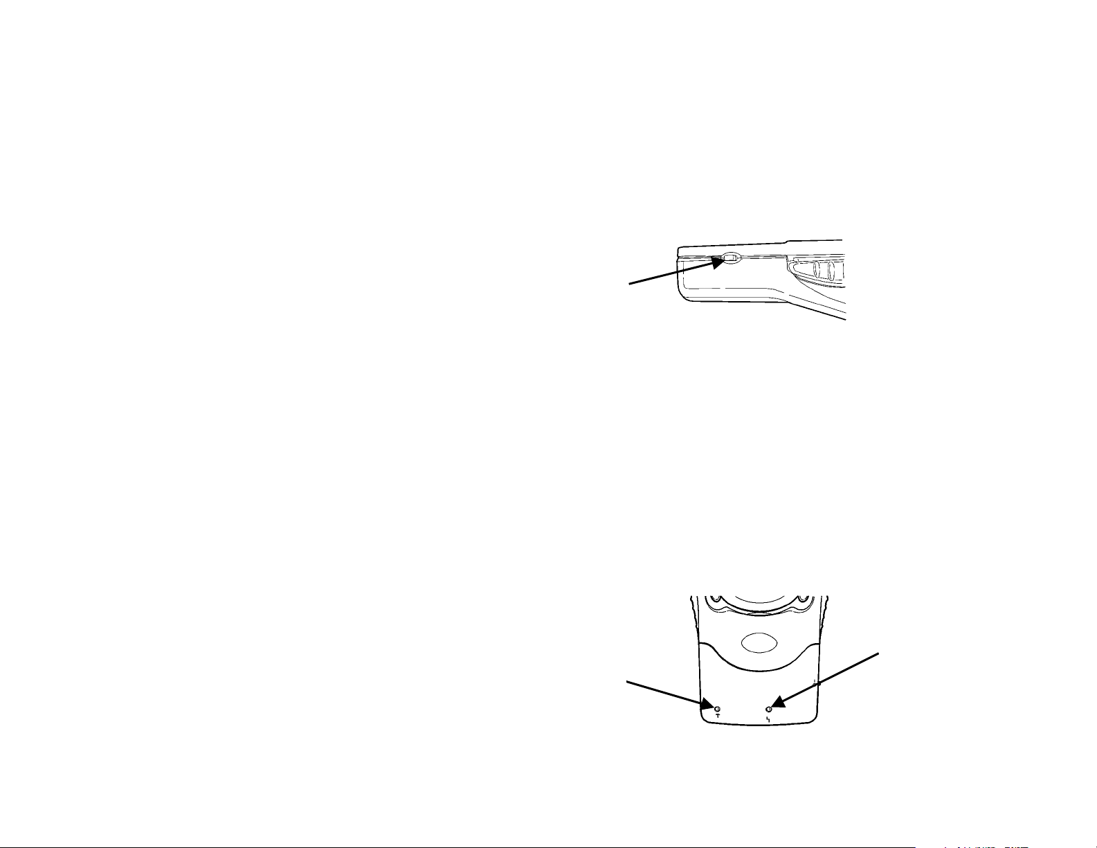
Linking the RF Modules
Despite there being no physical connection (a cable), the RF link device
and printer must still be linked so they can communicate. To set up the
link:
1. Turn off the RF link device, printer, and terminal. See the
documentation for the terminal and printer for more information.
Following is the RF link device’s power switch.
Power
Switch
2. Move the RF link device (with terminal inserted) and the printer
within three meters of each other.
3. Turn on the terminal.
4. Turn on the printer. Ready appears on its screen.
5. Turn on the RF link device. The linking process begins.
When the link is established, the RF link device’s Status LED (green)
blinks, and RF Ready appears on the printer’s screen.
If a problem occurs with the link, the Error LED (yellow) turns on. If
this occurs, see “Troubleshooting.”
Status LED
Error LED
Operating Instructions 3
Page 4

When you have linked the modules, they can talk with each other up to 20
feet apart.
NOTE: When you are not using the printer, terminal, and RF link device,
be sure to turn them off.
Scanning Bar Codes
To scan a bar code:
1. Point the scanner at a slight angle approximately 4 – 8 inches from
the bar code symbol.
2. Pull the trigger until you hear a beep, which indicates a complete
scan. If you let go of the trigger before the beep, the scan stops
immediately.
CAUTION: Do Not stare into the beam.
If the bar code does not scan:
♦ Change the angle of the scanner slightly and try again.
♦ Clean the scanner window.
♦ Move the scanner 4 – 8 inches away from the bar code. Adjust this
distance as needed to find the correct distance.
♦ Try scanning another bar code that you have scanned successfully. If
that scan is successful, the scanning problem is with the bar code.
♦ Move to a more dimly lit area.
♦ Be sure there are no voids in the bar code symbol.
4 Operating Instructions
Page 5

Using a Cable Connection
Optional. You do not necessarily have to use the RF link device with RF
communications. You can connect the RF link device to the printer with a
cable (part number 12029351).
To attach the cable, plug it into the port at the back of the unit.
To remove the cable, press the cable release and pull the cable away
from the port.
Cable Release
Operating Instructions 5
Page 6

Troubleshooting
Problems can occur with the scanner and RF communications.
Scanner Problems
If the scanner does not turn on, have your System Administrator check
♦ the terminal’s application to determine if it initializes the scanner in
the form’s activate event.
♦ that the terminal’s Ext. 5 volts option is set to
1. Tap the upper left corner of any screen.
2. Choose Settings from the drop-down menu.
3. Tap the System tab (at the bottom).
4. Tap the Symbol Settings icon.
5. Tap the Settings tab (at the bottom). The Ext. 5 volts drop-down
box appears in the middle of the screen that appears.
Always On
. To do so:
6 Operating Instructions
Page 7

RF Communication Problems
If the RF link device and the printer are not communicating, try each of
these suggestions to correct the problem.
♦ Change or recharge the terminal’s battery.
♦ Have your System Administrator ensure that the following
communication parameters are set on both the terminal and the
printer:
8 data bits
−
No parity
−
9600 baud
−
1 stop bit
−
DTR flow control (on the printer)
−
RTS/CTS flow control (on the terminal).
NOTE: The application on the terminal should be written with the
parameters built in.
♦ Re-link the printer and RF link device.
♦ Move the modules closer than three meters apart.
♦ Move the RF link device and printer around to find the best relative
position between the two.
Swap in new devices (printer or RF link device) to narrow the problem
♦
down to a particular device.
Make sure no other RF devices are within the 20-foot zone because
♦
they may obscure the intended linking.
Operating Instructions 7
Page 8

 Loading...