

Page 1

MONARCH PRINTER
CONTROL LANGUAGE
II
Graphics Manual
TCMPCL2GR Rev. AA 9/00
©1994 Monarch Marking Systems, Inc. All Rights Reserved.
Page 2

Each product and program carries a respective written warranty, the only warranty on which the
customer can rely. Monarch reserves the right to make changes in the product and the programs
and their availability at any time and without notice. Although Monarch has made every effort to
provide complete and accurate information in this manual, Monarch shall not be liable for any
omissions or inaccuracies. Any update will be incorporated in a later edition of this manual.
1994 Monarch Marking Systems, Inc. All rights reserved. No part of this publication may be
reproduced, transmitted, stored in a retrieval system, or translated into any language in any form,
by any means, without the written permission of Monarch Marking Systems, Inc.
Trademarks
Monarch is a registered trademark of Monarch Marking Systems, Inc.
Paxar is a trademark of Paxar Corporation.
1460, 6030, 9446, 9490, and 9494 are trademarks of Monarch Marking Systems, Inc.
Monarch Marking Systems, Inc.
170 Monarch Lane
Miamisburg, Ohio 45342
Page 3

Preface
Before you read this manual, review the information in your printer’s Packet
Reference Manual.
About This Manual_________________________________________
This manual provides information on how to create graphic packets for all
Monarch printers that support Monarch Printer Control Language (MPCL or
MPCLII).
Chapter 1 Provides a basic overview of creating graphics.
Chapter 2 Explains how to map out the graphic image using the
Hex or Run Length method.
Chapter 3 Explains how to create a graphic packet using
Graphic Header, Bitmap, Duplicate, Next-Bitmap,
Text, Constant text, Line, and Box Fields.
Chapter 4 Explains how to place a graphic image into a format.
Appendix A Contains the conversion charts for Binary to Hex and
Run Length.
Audience __________________________________________________
This manual is for the programmer who creates graphic packets and is familiar
with Binary and Hexadecimal numbers.
i
Page 4

MPCLII Graphics Manual
Terms To Know ___________________________________________
Bitmapped
Images
Compliance
Labels
Compliance
Label Overlay
Field This can be bitmap, next-bitmap, duplicate, text, non-
Field Definition Any string of elements pertaining to one field. A field
Format This is the layout or design for your supply.
Format Packet This is a packet that creates the format. Refer to the
Graphic Field This field is specified in the format packet. The values for
Graphic Packet This is a packet that creates a graphic bitmap image or a
These images are formed through a series of dots.
These are shipping labels used exclusively for a certain
retailer. The label complies with the retailer’s standards.
This is the “skeleton” of the compliance label that contains
the fixed fields (constant text, lines, etc.).
printable, graphic, bar codes, lines, or boxes. It is the
result of a field definition.
definition begins with a field identifier (such as B for
bitmap or D for duplicate).
definition of Packet for more information.
row and column position the graphic image on the supply.
compliance label overlay. Refer to the definition of Packet
for more information.
Graphic Header The first line of the graphic packet, immediately following
the start of packet ({). A graphic header must begin with
G, followed by various graphic elements.
Packet This is any string of characters contained within ({ }).
ii
Page 5

Table of Contents
1. Introduction......................................................................1-1
Overview of Compliance Labels ........................................................ 1-1
Overview of Bitmapped Images......................................................... 1-2
Determining a Method................................................................. 1-3
2. Designing the Graphic Image ......................................... 2-1
Designing Compliance Labels ........................................................... 2-1
Designing Bitmapped Images............................................................ 2-2
Special Considerations ............................................................... 2-2
Using the Hexadecimal Method .................................................. 2-3
Using the Run Length Encoding Method .................................... 2-5
Determining How to Store the Image ................................................ 2-7
Using RAM .................................................................................. 2-7
Using Temporary Storage ........................................................... 2-8
3. Creating a Graphic Packet ..............................................3-1
Positioning the Graphic Image .......................................................... 3-1
Within the Graphic Packet Header.............................................. 3-1
Within the Field............................................................................ 3-3
Within a Format........................................................................... 3-3
Graphic Header ................................................................................. 3-3
Bitmap Fields ..................................................................................... 3-5
Next-Bitmap Fields ............................................................................ 3-6
Duplicate Fields .................................................................................3-7
Constant Text Fields........................................................................ 3-10
Line Fields ....................................................................................... 3-10
Box Fields ........................................................................................ 3-10
Sample Compliance Graphic Packet............................................... 3-11
Sample Hex Graphic Packet ........................................................... 3-13
Sample Run Length Packet............................................................. 3-15
iii
Page 6

MPCLII Graphics Manual
4. Placing the Graphic in a Format .....................................4-1
Including the Graphic Field................................................................ 4-2
Sample Compliance Label................................................................. 4-4
Sample Bitmap Graphic Image.......................................................... 4-6
Appendix A- Conversion Charts ......................................... A-1
Binary to Hex Conversion Chart ........................................................A-2
Dot to Run Length Encoding Chart ...................................................A-6
iv
Page 7

Chapter 1. Introduction
You can use graphic packets to create
♦ Compliance Labels.
♦ Bitmapped images.
This chapter gives an overview of both approaches. To include a graphic
packet within your format, your format must contain a Graphic Field. Refer to
Chapter 4, “Placing the Graphic in a Format,” for more information.
Overview of Compliance Labels______________________________
You can create compliance labels by using a graphic packet for the fixed fields
and a format packet for the variable fields of your compliance label. The fixed
fields of a compliance label are composed of text, lines, or boxes, which are
repeated on each label. The variable fields are composed of text, bar codes,
and order information, which change with each label. Using a graphic packet
for the fixed fields saves time, because the printer does not have to image all
the lines or boxes each time the compliance label is printed.
Also, using a graphic packet for a compliance label reduces the number of
fields in your format. Formats have a maximum number of fields per packet
(0-99). However, you can bypass that requirement by placing your
compliance layout in a graphic packet. When you process your formats, you
only need one line to call the graphic packet.
1-1
Page 8

MPCLII Graphics Manual
The following example shows how to call a graphic packet from within a format
packet.
{ Start of Packet
F,1,A,R,E,400,400,”RDCI”¦ Format Header
G,57,0,0,0,0¦ Call the graphic packet
. variable information
. variable information
} End of Packet
Once you have your compliance label format set up, all you need to do is add
the variable sections (bar codes, addresses, and order information) to the
format packet.
To see a sample compliance label graphic packet, refer to Chapter 3,
“Creating a Graphic Packet.” To see a sample compliance label using a
graphic packet within a format, refer to Chapter 4, “Placing the Graphic in a
Format.”
Overview of Bitmapped Images _____________________________
1-2
A printed image is formed through a series of dots. Each square on the grid
below represents a dot on the printhead. The graphic image is created by
blackening dots in a specific pattern.
You can print varying shades of gray according to the concentration of dots on
the image.
When the dots are printed together, the end result is a graphic image.
Page 9

1. Introduction
Determining a Method
You can use one of two methods to map out your graphic image:
Hexadecimal Method
The dot sequences are segmented into Binary numbers, and then
converted to Hexadecimal numbers.
A graphic using gray-scaling, several slanted lines, or several vertical
lines typically translates more efficiently with Hex Representation.
Run Length Encoding Method
The dot sequences are segmented into black and white strings within
a row. The total count of each white string is converted to a lowercase
letter, corresponding to numeric value. The total count of each black
string is converted to an uppercase letter, corresponding to numeric
value. This method is more complicated, but can reduce imaging time
for graphics that contain repetitive rows of dots.
A graphic with horizontal lines or very few white-to-black borders
typically translates more efficiently with Run Length Encoding
The most efficient encoding method depends on how complicated your
graphic image is and whether or not imaging time is a concern. You may want
to experiment with both encoding methods to get optimal performance.
.
1-3
Page 10

MPCLII Graphics Manual
1-4
Page 11

Chapter 2. Designing the Graphic Image
This chapter describes
♦ how to design compliance labels.
♦ how to design bitmapped images.
♦ special considerations.
♦ how to map out the graphic image by the Hex and Run Length
methods.
♦ how to store the graphic image.
The information presented in this chapter deals with Binary and Hexadecimal
numbers. Appendix A, “Conversions Charts,” contains the following charts:
♦ Binary to Hexadecimal
♦ Dot to Run Length Encoding
Designing Compliance Labels________________________________
To use a graphic packet to design your compliance label:
1. Decide which fields are fixed (constant text, lines, boxes) and which
fields are variable (addresses and shipping information).
2. Lay out your compliance label as you would any other format. Refer
to Chapter 3, “Creating a Graphic Packet,” for more information.
2-1
Page 12
MPCLII Graphics Manual
Designing Bitmapped Images________________________________
Once you determine the encoding method to use, you can begin mapping out
your graphic image.
NOTE: The image that you map must be an upside down mirror image of the
final result.
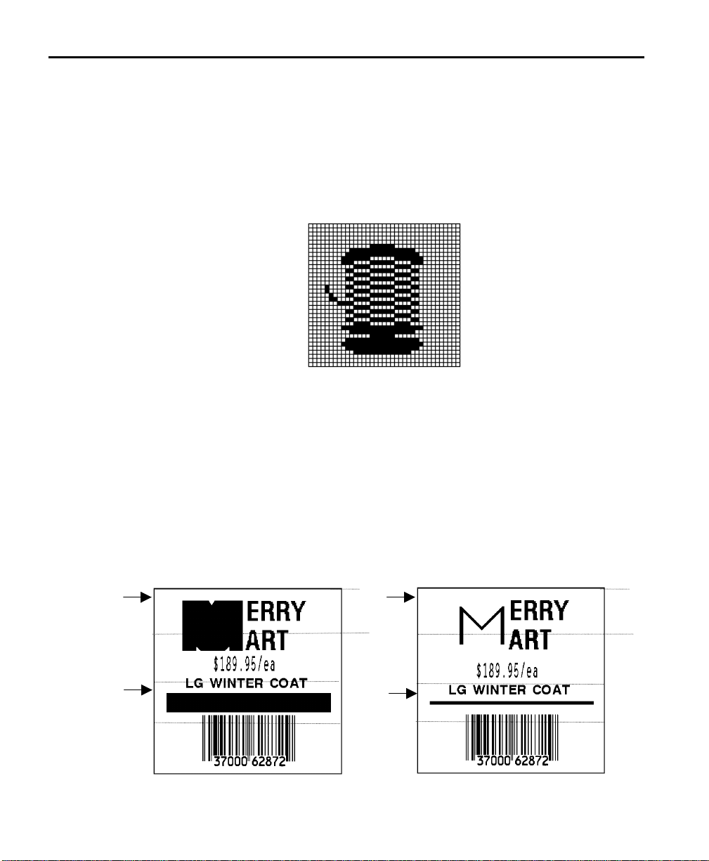
Special Considerations
Solid black print cannot exceed 20% (for the 9490/ 9494 printers) or 30%
(for the 9446/ 1460/ 6030 printers) of any given square inch of the
supply. If your black print exceeds this limit, you may lose data or damage the
printer.
2-2
In the first label, the large “M” logo and thick black line exceed the allowed
black to white print ratio. In the second label, the large “M” logo does not
exceed the black to white print ratio.
--------------- 2 inches -------------- --------------- 2 inches --------------
0.5”
Exceeds
limit
Exceeds
limit
Does not
exceed
limit
Does not
exceed
limit
0.5”
Page 13

2. Designing the Graphic Image
Using the Hexadecimal Method
The following steps explain how to derive a Hexadecimal character string from
a bitmapped graphic.
Each square on the grid represents a dot. A black square indicates the dot is
ON, and a white square indicates the dot is OFF. A sequence of Binary
numbers, called a bit pattern or bitmap, determines what dots are on and off.
The numbers "0" and "1" are used for this purpose. The number "1" turns a
dot on and "0" turns a dot off.
1. Assign 1 to every black square and 0 to every white square.
00000000000000000000000000000000000000000000000000111111111111111111111111110000000000000000000000000000
00000000000000000000000000000000000000011111111111000000000000000000000000001111111110000000000000000000
00000000000000000000000000000000001111100000000000000000000000000000000000000000000001111110000000000000
00000000000000000000000000000011110000000000000000111111111111111111111111110000000000000001111000000000
00000000000000000000000001111100001111111111111111111111111111111111111111111111111111111110000111110000
00000000000000000000000110000011111111111111111111111111111111111111111111111111111111111111111000001100
00000000000000000000000110001111111111111111111111111111111111111111111111111111111111111111111111111110
00000000000000000000000111111111111111111111111111111111111111111111111111111111111111111111111111111110
00000000000000000000000111111111111111111111111111111000000000000000000011111111111111111111111111111110
00000000000000000000000111111111111111111111000000000000000000000000000000000000011111111111111111111100
00000000000000000000000001111111100000000000000000000111111111111111111100000000000000000011111111110000
00000000000000000000000000011111110000000000000000000111111111111111111100000000000000000001111111000000
00000000000000000000000000011100000000111111111111111111111111111111111111111111111111100000000111000000
00000000000000000000000000000000001111111111111111111111111111111111111111111111111111111110000111000000
00000000000000000000000000000011111111111111000000000000000000000000000000000000011111111111111000000000
00000010000000000000000000011111110000000000000000000111111111111111111100000000000000000001111111000000
00000011000000000000000000011100000000111111111111111111111111111111111111111111111111100000000111000000
00000001111000000000000000000000001111111111111111111111111111111111111111111111111111111110000111000000
00000000111000000000000000000011111111111111000000000000000000000000000000000000011111111111111000000000
00000000111111000000000000011100000000111111111111111111111111111111111111111111111111100000001111000000
00000000111111100000000000000000001111111111111111111111111111111111111111111111111111111110001111000000
2-3
Page 14

MPCLII Graphics Manual
2. Section off the grid in columns of eight. If any rows are not divisible by
3. One row at a time, convert each group of eight Binary digits to
8, add enough 0's to complete a column.
00000000 00000000 00000000 00000000 00000000 00000000 00111111 11111111 11111111 11110000 00000000 00000000 00000000
00000000 00000000 00000000 00000000 00000001 11111111 11000000 00000000 00000000 00001111 11111000 00000000 00000000
00000000 00000000 00000000 00000000 00111110 00000000 00000000 00000000 00000000 00000000 00000111 11100000 00000000
00000000 00000000 00000000 00000011 11000000 00000000 00111111 11111111 11111111 11110000 00000000 00011110 00000000
00000000 00000000 00000000 01111100 00111111 11111111 11111111 11111111 11111111 11111111 11111111 11100001 11110000
00000000 00000000 0000000110000011 11111111 11111111 11111111 11111111 11111111 11111111 11111111 11111110 00001100
00000000 00000000 0000000110001111 11111111 11111111 11111111 11111111 11111111 11111111 11111111 11111111 11111110
00000000 00000000 00000001 11111111 11111111 11111111 11111111 11111111 11111111 11111111 11111111 11111111 11111110
00000000 00000000 00000001 11111111 11111111 11111111 11111000 00000000 00000000 11111111 11111111 11111111 11111110
00000000 00000000 00000001 11111111 11111111 11110000 00000000 00000000 00000000 00000000 01111111 11111111 11111100
00000000 00000000 00000000 01111111 10000000 00000000 00000111 11111111 11111111 00000000 00000000 00111111 11110000
00000000 00000000 00000000 00011111 11000000 00000000 00000111 11111111 11111111 00000000 00000000 00011111 11000000
00000000 00000000 00000000 00011100 00000011 11111111 11111111 11111111 11111111 11111111 11111110 0000000111000000
00000000 00000000 00000000 00000000 00111111 11111111 11111111 11111111 11111111 11111111 11111111 1110000111000000
00000000 00000000 00000000 00000011 11111111 11110000 00000000 00000000 00000000 00000000 01111111 11111110 00000000
00000010 00000000 00000000 00011111 11000000 00000000 00000111 11111111 11111111 00000000 00000000 00011111 11000000
00000011 00000000 00000000 00011100 00000011 11111111 11111111 11111111 11111111 11111111 11111110 0000000111000000
00000001 11100000 00000000 00000000 00111111 11111111 11111111 11111111 11111111 11111111 11111111 1110000111000000
00000000 11100000 00000000 00000011 11111111 11110000 00000000 00000000 00000000 00000000 01111111 11111110 00000000
00000000 11111100 00000000 00011100 00000011 11111111 11111111 11111111 11111111 11111111 11111110 00000011 11000000
00000000 11111110 00000000 00000000 00111111 11111111 11111111 11111111 11111111 11111111 11111111 11100011 11000000
Hexadecimal values, using the Binary to Hex Conversion Chart.
2-4
starting at position 49 ...
00111111 = 3F
11111111 = FF
11111111 = FF
11110000 = F0
4. Write the Hexadecimal values for each row as a continuous string.
row 1, position 49 = 03FFFFFF00000
NOTE: All Hex numbers must be two digits. For example, write Hex 0
as 00, or Hex E as 0E.
5. Repeat steps 3 through 4 for each row on the grid.
6. Insert the Hexadecimal values in syntax format as shown in Chapter 3,
“Creating a Graphic Packet.”
A sample Hex Graphic Packet is also shown in Chapter 3.
Page 15

2. Designing the Graphic Image
Using the Run Length Encoding Method_______________________
The following steps explain how to derive a Run Length character string from a
bitmapped graphic.
Each square on the grid represents a dot. A black square indicates the dot is
ON, and a white square indicates the dot is OFF.
NOTE: For visual clarity, the following example shows "1" to indicate when a
square is ON, and "0" to indicate when a square is OFF. You do not
have to convert your dots when using the Run Length method.
00000000 00000000 00000000 00000000 00000000 00000000 00111111 11111111 11111111 11110000 00000000 00000000 00000000
00000000 00000000 00000000 00000000 00000001 11111111 11000000 00000000 00000000 00001111 11111000 00000000 00000000
00000000 00000000 00000000 00000000 00111110 00000000 00000000 00000000 00000000 00000000 00001111 11000000 00000000
00000000 00000000 00000000 00000011 11000000 00000000 00111111 11111111 11111111 11110000 00000000 00011110 00000000
00000000 00000000 00000000 01111100 00111111 11111111 11111111 11111111 11111111 11111111 11111111 11100001 11110000
00000000 00000000 0000000110000011 11111111 11111111 11111111 11111111 11111111 11111111 11111111 11111110 00001100
00000000 00000000 0000000110001111 11111111 11111111 11111111 11111111 11111111 11111111 11111111 11111111 11111110
00000000 00000000 00000001 11111111 11111111 11111111 11111111 11111111 11111111 11111111 11111111 11111111 11111110
00000000 00000000 00000001 11111111 11111111 11111111 11111000 00000000 00000000 11111111 11111111 11111111 11111110
00000000 00000000 00000001 11111111 11111111 11110000 00000000 00000000 00000000 00000000 01111111 11111111 11111100
00000000 00000000 00000000 01111111 10000000 00000000 00000111 11111111 11111111 00000000 00000000 00111111 11110000
00000000 00000000 00000000 00011111 11000000 00000000 00000111 11111111 11111111 00000000 00000000 00011111 11000000
00000000 00000000 00000000 00011100 00000011 11111111 11111111 11111111 11111111 11111111 11111110 0000000111000000
00000000 00000000 00000000 00000000 00111111 11111111 11111111 11111111 11111111 11111111 11111111 1110000111000000
00000000 00000000 00000000 00000011 11111111 11110000 00000000 00000000 00000000 00000000 01111111 11111110 00000000
00000000 00000000 00000000 00011111 11000000 00000000 00000111 11111111 11111111 00000000 00000000 00011111 11000000
00000000 00000000 00000000 00011100 00000011 11111111 11111111 11111111 11111111 11111111 11111110 0000000111000000
00000000 00000000 00000000 00000000 00111111 11111111 11111111 11111111 11111111 11111111 11111111 1110000111000000
00000000 00000000 00000000 00000011 11111111 11110000 00000000 00000000 00000000 00000000 01111111 11111110 00000000
00000000 00000000 00000000 00011111 11000000 00000000 00000111 11111111 11111111 00000000 00000000 00011111 11000000
00000000 00000000 00000000 00011100 00000011 11111111 11111111 11111111 11111111 11111111 11111110 0000000111000000
00000000 00000000 00000000 00000000 00111111 11111111 11111111 11111111 11111111 11111111 11111111 1110000111000000
00000000 00000000 00000000 00000011 11111111 11110000 00000000 00000000 00000000 00000000 01111111 11111110 00000000
00000000 00000000 00000000 00011111 11000000 00000000 00000111 11111111 11111111 00000000 00000000 00011111 11000000
00000000 00000000 00000000 00011100 00000011 11111111 11111111 11111111 11111111 11111111 11111110 0000000111000000
00000000 00000000 00000000 00000000 00111111 11111111 11111111 11111111 11111111 11111111 11111111 1110000111000000
00000000 00000000 00000000 00000011 11111111 11110000 00000000 00000000 00000000 00000000 01111111 11111110 00000000
00000000 00000000 00000000 00011111 11000000 00000000 00000111 11111111 11111111 00000000 00000000 00011111 11000000
00000000 00000000 00000000 00011100 00000011 11111111 11111111 11111111 11111111 11111111 11111110 0000000111000000
00000000 00000000 00000000 00000000 00111111 11111111 11111111 11111111 11111111 11111111 11111111 1110000111000000
00000000 00000000 00000000 00000011 11111111 11110000 00000000 00000000 00000000 00000000 01111111 11111110 00000000
00000010 00000000 00000000 00011111 11000000 00000000 00000111 11111111 11111111 00000000 00000000 00011111 11000000
00000011 00000000 00000000 00011100 00000011 11111111 11111111 11111111 11111111 11111111 11111110 0000000111000000
00000001 11100000 00000000 00000000 00111111 11111111 11111111 11111111 11111111 11111111 11111111 1110000111000000
00000000 11100000 00000000 00000011 11111111 11110000 00000000 00000000 00000000 00000000 01111111 11111110 00000000
00000000 11111100 00000000 00011100 00000011 11111111 11111111 11111111 11111111 11111111 11111110 00000011 11000000
00000000 11111110 00000000 00000000 00111111 11111111 11111111 11111111 11111111 11111111 11111111 11100011 11000000
1. Count the number of consecutive OFF or ON dots in a row. Write the
number of consecutive dots in sequence for the first row on the grid.
Write "ON" or "OFF" after each number to indicate ON or OFF dots.
(row 1, position 50) 26 on
(row 2, position 39) 11 on, 26 off, 9 on
(row 3, position 34) 5 on, 45 off, 6 on
.
.
2-5
Page 16

MPCLII Graphics Manual
2. Replace each number you have written with its corresponding code
3. Write the letter codes in sequence, uninterrupted, for each row.
from the Dot to Run Length Encoding Chart provided in Appendix A,
“Conversion Charts.” Be sure to use CAPITAL letters for black dots
and lowercase letters for white dots.
26 on (Z)
11 on (K), 26 off (z), 9 on (I)
.
.
If the number is greater than 26, write z, followed by the letter
corresponding to the amount over 26. For example, to represent 45
off dots, write zs.
5 on (E), 45 off (zs), 6 on (F)
.
.
(row 1,position 50) Z
(row 2,position 39) KzI
(row 3,position 34) EzsF
(row 4,position 30) DpZoD
.
.
NOTE: If the end of the line specifies OFF dots (lowercase letters),
the ending lowercase letters can be omitted. For example,
uZFu can be written as uZF.
2-6
4. Repeat steps 1 through 5 for each row on the grid.
5. Insert the code values using the syntax shown in Chapter 3, “Creating
a Graphic Packet.”
A sample Run Length Graphic Packet is also shown in Chapter 3.
Page 17

2. Designing the Graphic Image
Determining How to Store the Image _________________________
Once you have mapped out your graphic image, determine how you want to
store it. You have two options:
♦ RAM
♦ Temporary Storage
Using RAM
You should use RAM when the graphic image is used by several formats,
because you only have to send the graphic image once. This eliminates the
need to send the graphic image repeatedly. Refer to Chapter 4, “Placing the
Graphic in a Format,” for more information about calling the graphic packet in
a format. Graphics smaller than approximately 1/2 inch by 1/2 inch can be
stored in printer RAM and referenced by the graphic ID number.
NOTE: Graphics are stored in the format buffer and remain there until another
graphic packet is sent or the printer is turned off.
To determine if you have enough room to store the graphic image in RAM:
1. Determine the file size of your graphic image with this formula:
(# of rows) x (16 + (width/4)) + 35 / 1024
NOTE: Width is the width of your graphic image in dots.
For example, if your graphic image was a 1/2 inch by a 1/2 inch,
your file size would be approximately 4 bytes.
NOTE: The above calculation is an estimate of your file size.
Be sure to round up to the nearest 1/2K, because
memory is allocated in 1/2K increments.
2. If the size of the graphic image is greater than the amount of available
memory in RAM, you must send the graphic image to temporary
storage, or reallocate memory. For information on reallocating
memory, refer to your printer’s Packet Reference Manual.
NOTE: Large graphics require large amounts of memory space in
RAM and can quickly use up space.
2-7
Page 18

MPCLII Graphics Manual
Using Temporary Storage
You should use temporary storage when the graphic image is used only in one
format or your graphic image is very large. Graphic data in temporary storage
is held in the image buffer until the graphic is printed and then it is cleared
from memory. Temporary graphics are also cleared from memory when you
send a new batch or update batch. You can use the same graphic image
multiple times on a format. Send the graphic image to the printer after the
format to which it applies.
NOTE: If a graphic is stored in temporary storage, do not place a graphic field
in the format as described in "Placing the Graphic in a Format." This
will cause an error. Instead, position the graphic image by using the
row and column locations in the Graphic Packet Header.
Image memory (temporary storage) will accept a graphic packet with the
dimensions listed in the table below.
Rows long Dots per row Printer
1152 768 9490/9494
1536 768 9446/1460
2-8
701 352 6030
NOTE: You cannot create a graphic image larger than the length of your
supply without reallocating memory. Refer to your printer’s Packet
Reference Manual for information on reallocating memory.
Page 19

Chapter 3. Creating a Graphic Packet
Your graphic packet can contain:
♦ bitmapped fields (for bitmapped images)
♦ constant text fields
♦ lines
♦ boxes
Images using Hex Representation or Run Length Encoding are bitmapped
images. Refer to Chapter 2, "Designing the Graphic Image," to map out your
bitmapped image.
Once you lay out your graphic image, you are ready to define a graphic
packet. This packet generates the graphic image that you use in a format.
Positioning the Graphic Image_______________________________
This section explains how to position the graphic image
♦ within a graphic packet header.
♦ within a field of a graphic packet.
♦ within a format.
Within the Graphic Packet Header
When you are using RAM, the row and
column parameters in the Graphic Header
are usually 0,0, because placement is
controlled by the Graphic Field in your
Format. This is especially true when
designing a compliance label overlay.
When you are using temporary storage,
these parameters control the placement of the graphic image on the supply.
NOTE: The area enclosed within the dotted lines represents the graphic
image starting at 0,0 (as defined in the Graphic Header).
3-1
Page 20

MPCLII Graphics Manual
NOTE: The area enclosed within the dotted lines represents the graphic
Within the Field
If you want a fixed amount of white space around
your graphic image, use something other than 0 for
row and/ or column.
image starting at 0,0 with a fixed amount of white space (10,10)
around the graphic image.
The row and column parameters in a Bitmap, Constant
Text, Line, or Box Field control where an individual field
or bitmapped row begins in relation to the coordinates
defined in the Graphic Header.
NOTE: The bottom of the triangle in this example
represents the first field of the graphic packet
starting at 10,0.
Within a Format
When you define the Graphic Field within your format, the row and column
parameters represent where on the format to place the graphic image.
If you are doing a compliance label, these
numbers are usually 0,0, because your
compliance label covers the entire supply.
Refer to Chapter 4, “Placing the Graphic in a
Format,” for a sample compliance label.
If you are placing a graphic (a logo, for
example) within a certain area on your
supply, enter the starting position (bottom left
corner) of the graphic image.
NOTE: This label shows the triangle “logo” beginning (the bottom left corner)
3-2
at 400,75 as defined in the Graphic Field.
Page 21

3. Creating a Graphic Packet
Graphic Header ____________________________________________
Every graphic packet must contain a Graphic Header. This is the first thing
you enter. It identifies and provides important measurement and formatting
information for the graphic. Bitmap, duplicate, next-bitmap, constant text, line,
and box fields follow the Graphic Header, if they are used.
G1 HEADER
G2 GRAPH ID
G3 ACTION
G4 DEVICE
G5 UNITS
G6 ROW
G7 COLUMN
G8 MODE
G A 0
Syntax {G,graphID,action,device,units,row,col,mode,”name”¦
{ Start of packet for MPCL file.
G Identifies a graphic packet.
graphID A number from 1 to 999 to identify the graphic image.
action Enter A to add the packet to printer memory.
device Printer device that stores the graphic.
R Volatile RAM (format must contain a Graphic Field).
T Temporary storage.
NOTE: Graphics require a lot of RAM and can quickly use up
space. When using graphics larger than 1/2 inch by 1/2 inch,
temporary storage is recommended.
units Unit of measure for graphic fields. All units used in the Graphic Packet must
use the units selected here.
G9 NAME
E English. Measured in 1/100 inches.
M Metric. Measured in 1/10 millimeters.
G Dots. These printers print 192 dots per inch.
NOTE: For bitmapped graphics, G is the only valid option.
3-3
Page 22

MPCLII Graphics Manual
row Distance between the bottom of the graphic image area and the first bitmap
line. This is usually 0, unless you want a fixed amount of white space around
the graphic image. Refer to “Positioning the Graphic Image,” earlier in this
chapter for more information. Must be measured in selected units.
col Distance between the left edge of the graphic image area and the left edge of
first bitmap line. This is usually 0, unless you want a fixed amount of white
space around the graphic image. Refer to “Positioning the Graphic Image,”
earlier in this chapter for more information. Must be measured in selected
units.
mode Imaging mode. Enter 0. This is the only option supported by these printers.
“name” Assign a name (for reference only) to the graphic. The name must be 1 - 8
characters in length. Enclose in quotation marks (example: “Name").
Example {G,99,A,R,G,0,0,0,"99Wire"¦
♦ Graphic header
♦ Image is identified by number 99
♦ Image being Added
♦ Image stored in volatile RAM
♦ Image uses Graphic (dot) measurement
♦ Image will be placed according to the row and column parameters
specified in the Graphic Field within the format.
♦ Imaging mode is 0
♦ Image is called 99Wire
3-4
Page 23

3. Creating a Graphic Packet
Bitmap Fields _____________________________________________
This defines one row of dots, starting at a specific row and column within the
graphic image. Each unique row of dots requires a bitmap field. A bitmap field
can later be repeated by using a duplicate field.
Syntax B,row,column,algorithm,"data"¦
B Identifies a bitmap field.
row Distance (in dots) from the graphic image’s bottom margin to the bitmap line.
Unit of Measure 9490/9494 9446/1460 6030
English 0- 599 0- 799 0- 372
Metric 0- 1521 0- 2033 0- 945
Dots 0- 1151 0- 1536 0- 701
column Distance (in dots) from the graphic image’s left edge to the bitmap line.
Unit of Measure 9490/9494/9446/1460 6030
English 0- 399 0- 183
Metric 0- 1015 0- 465
Dots 0- 768 0-352
algorithm Coding method to use for bitmap data.
H Hex Representation
R Run Length Encoding
"data" Character string made up of Hexadecimal or Run Length encoding. Do not
put spaces or any other character between the numbers.
Example B,39,56,H,“3FFFFFF0”¦
♦ Bitmapped graphic field
♦ Image begins 39 dots from the bottom of the graphic area
♦ Image begins 56 dots from the left edge of the graphic area
♦ Hex representation is used
3-5
Page 24

MPCLII Graphics Manual
Next-Bitmap Fields ________________________________________
This field uses the previous field’s row and column locations. It allows you to
use the bitmap or duplicate field data without having to recalculate row and
column locations. This field represents one row of dots on the image.
Syntax N,adjdir,adjamt,algorithm,"data"¦
N Identifies a next-bitmap field.
adjdir Do you want to increment or decrement the row count? (Insert the duplicate
line after or before the current row?)
0 Increments (Inserts after)
1 Decrements (Inserts before)
For example:
B,50,35,R,”GsSsG”
N,0,R,”DpZoD”¦
prints a next-bitmap field on row 51 at column 35.
adjamt Amount of row adjustment in dot rows. Using 0 overwrites the same line.
algorithm Coding method for bitmap data.
H Hex Representation
R Run Length Encoding
"data" Character string made up of Hexadecimal or Run Length encoding. Do not
put spaces or any other character between the Hex numbers or Run Length
code letters.
Example B,39,56,H,”3FFFFFF0”¦
N,0,1,H,"000000E00000"¦
♦ Next-Bitmap graphic field information is printed on row 40
(increments row count)
♦ Amount of adjustment is 1 row
♦ Hex representation is used
¦
3-6
Page 25

3. Creating a Graphic Packet
Duplicate Fields ___________________________________________
If a line of data is identical to a previous bitmap or next-bitmap field, the
duplicate field allows you to repeat the dot sequence without retyping the data.
A duplicate field represents one row of dots on the image.
NOTE: Duplicate fields are useful when you have a graphic with a lot of
repetition.
Syntax D,adjdir,adjamt,count¦
D Identifies a duplicate field.
adjdir Do you want to increment or decrement the row count? (Insert the duplicate
line after or before the current row?)
0 Increments (inserts after)
1 Decrements (inserts before)
For example:
B,50,35,R,”GsSsG”
D,0,20,2¦
inserts row 50 again at row 70 and row 90. Rows 70 and 90 do not
have to be defined later.
adjamt Amount of row adjustment in dot rows. The above example adjusts the
duplicate field to image on row 70 and 90 (adding 20 to the current row count.)
count Number of times to duplicate. (How many times do you want to repeat the
line?)
¦
Example B,117,24,H,”03FFFFFFFFFFFFFFFFFFFC”¦
D,0,1,2¦
♦ Indicates a duplicate field
♦ Images the duplicate line after (0) the bitmap line
♦ Duplicates the preceding bitmap line twice (at row 118 and 119)
3-7
Page 26

MPCLII Graphics Manual
The following fields (constant text, line, and box field) can be used in a graphic
packet to create a compliance label overlay.
Constant Text Fields _______________________________________
A constant text field consists of a set of fixed text. Constant text fields can
appear either in graphic packets or format packets.
For information on using constant text fields, see "Defining Constant Text
Fields" in your printer’s Packet Reference Manual.
Line Fields ________________________________________________
The Line field in a graphic packet is identical to the line field in a format packet.
For information on using line fields, see "Defining Line Fields" in your printer’s
Packet Reference Manual.
For information on positioning a line within the graphic image, refer to
“Positioning the Graphic Image,” earlier in this chapter. Define the row and
column parameters in the units of measure selected in the Graphic Header.
Box Fields ________________________________________________
The Box (Quadrilateral) field in a graphic packet is identical to the quadrilateral
field in a format packet. For information on using box fields, see "Defining
Boxes" in your printer’s Packet Reference Manual.
For information on positioning a box within the graphic image, refer to
“Positioning the Graphic Image,” earlier in this chapter. Define the row and
column parameters in the units of measure selected in the Graphic Header.
3-8
Page 27

3. Creating a Graphic Packet
Sample Compliance Graphic Packet __________________________
A sample compliance graphic packet is shown below.
{ Start of packet
G,57,A,R,E,0,0,0,"OVERLAY"¦ Graphic Header
L,V,500,155,90,85,3¦ Line field
L,V,298,245,90,102,3¦ Line field
L,V,500,2,0,390,3¦ Line field
L,V,400,2,0,390,3¦ Line field
L,V,298,2,0,390,3¦ Line field
L,V,200,2,0,390,5¦ Line field
C,560,10,0,2,2,2,B,L,0,0,"FROM:",0¦ Constant field
C,560,160,0,2,2,2,B,L,0,0,"CARRIER:",0¦ Constant field
C,529,160,0,2,2,2,B,L,0,0,"PRO NUMBER:",0¦ Constant field
C,511,160,0,2,2,2,B,L,0,0,"B/L NUMBER:",0¦ Constant field
C,472,10,0,2,2,2,B,L,0,0,"TO:",0¦ Constant field
C,387,10,0,2,1,1,B,L,0,0,"SHIP TO POSTAL CODE",0¦ Constant field
C,391,250,0,2,1,1,B,L,0,0,"APPOINTMENT NUMBER:",0¦ Constant field
C,358,250,0,2,1,1,B,L,0,0,"ORDER TYPE:",0¦ Constant field
C,327,250,0,2,1,1,B,L,0,0,"ITEM:",0¦ Constant field
C,190,8,0,2,1,1,B,L,0,0,"UPC SHIPPING CONTAINER CODE",0¦ Constant field
C,548,6,0,2,1,1,B,L,0,0,"MONARCH MARKING SYSTEMS",0¦ Constant field
C,538,6,0,2,1,1,B,L,0,0,"170 MONARCH LANE",0¦ Constant field
C,528,6,0,2,1,1,B,L,0,0,"P.O. BOX 608",0¦ Constant field
C,518,6,0,2,1,1,B,L,0,0,"DAYTON, OHIO 45401",0¦ Constant field
C,462,313,0,2,4,3,B,L,0,0,"#",0¦ Constant field
} End of packet
The sample compliance label overlay on the following page was created with
this packet, using the format provided in Chapter 4, “Placing the Graphic in a
Format.”
3-9
Page 28

MPCLII Graphics Manual
3-10
Page 29

3. Creating a Graphic Packet
Sample Hex Graphic Packet _________________________________
{G,99,A,R,G,0,0,0,"99WIRE"¦
B,39,48,H,"3FFFFFF0"¦
B,40,32,H,"01FFC000000FF8"¦
B,41,32,H,"3E00000000000FC0"¦
B,42,24,H,"03C0003FFFFFF0000F"¦
B,43,24,H,"7C3FFFFFFFFFFFFFE1F0"¦
B,44,16,H,"0183FFFFFFFFFFFFFFFF06"¦
B,45,16,H,"018FFFFFFFFFFFFFFFFFFE"¦
B,46,16,H,"01FFFFFFFFFFFFFFFFFFFE"¦
B,47,16,H,"01FFFFFF80001FFFFFFFFE"¦
B,48,16,H,"01FFFFF0000000007FFFFC"¦
B,49,24,H,"7F800007FFFF00003FF0"¦
B,50,24,H,"1FC00007FFFF00001FC0"¦
D,0,4,4¦
B,51,24,H,"1C03FFFFFFFFFFFE01C0"¦
D,0,4,4¦
B,52,32,H,"3FFFFFFFFFFFFFE1C0"¦
D,0,4,4¦
B,53,24,H,"03FFF0000000007FFE"¦
D,0,4,4¦
B,70,0,H,"0400001FC00007FFFF00001FC0"¦
B,71,0,H,"0600001C03FFFFFFFFFFFE01C0"¦
B,72,0,H,"030000003FFFFFFFFFFFFFE1C0"¦
B,73,0,H,"01000003FFF0000000007FFE"¦
B,74,8,H,"FC001C03FFFFFFFFFFFE00C0"¦
B,75,8,H,"FE00003FFFFFFFFFFFFFE0C0"¦
B,76,8,H,"1FF803FFF0000000007FFE"¦
B,77,8,H,"0FFFCFFC00000000000001C0"¦
B,78,16,H,"FFDF000FFFFFFFFF8003C0"¦
B,79,16,H,"7FFFC00007FFFF00001FC0"¦
B,80,24,H,"1C03FFFFFFFFFFFE01C0"¦
D,0,4,4¦
B,81,32,H,"3FFFFFFFFFFFFFE1C0"¦
D,0,4,4¦
B,82,24,H,"03FFF0000000007FFE"¦
D,0,4,3¦
B,83,24,H,"1FC00007FFFF00001FC0"¦
D,0,4,3¦
3-11
Page 30

MPCLII Graphics Manual
Sample Hex Graphic Packet (continued)
B,98,24,H,"03FFFFFFFFFFFFFFF0"¦
B,99,24,H,"07FFFFFFFFFFFFFFFC"¦
B,100,24,H,"1FF9FFFFFFFFFFFFFF"¦
B,101,24,H,"3FFE0007FFFF8000FF80"¦
B,102,24,H,"391E0027FFFF803FFFC0"¦
B,103,24,H,"1C7FFFFFFFFFFFFFFFC0"¦
B,104,24,H,"1FC1FFFFFFFFFFFF1FC0"¦
B,105,24,H,"0FFDFFFFFFFFFFE0FF"¦
B,106,24,H,"FFFFFFFFFFFFFFF8"¦
B,107,32,H,"3FFFFFFFFFFFFFE0"¦
B,108,32,H,"03FFFFFFFFFFFF"¦
B,109,48,H,"07FFFF80"¦
D,0,1,2¦
B,111,48,H,"FFFFFFFF"¦
B,112,32,H,"FFFF00000000FFE0"¦
B,113,24,H,"078000FFFFFFFF001F"¦
B,114,24,H,"78FFFFFFFFFFFFFFE060"¦
B,115,16,H,"0187FFFFFFFFFFFFFFFC18"¦
B,116,16,H,"027FFFFFFFFFFFFFFFFFF2"¦
B,117,16,H,"03FFFFFFFFFFFFFFFFFFFC"¦
D,0,1,2¦
B,120,16,H,"01FFFFFFFFFFFFFFFFFFF8"¦
B,121,24,H,"FEFFFFFFFFFFFFFFFFE0"¦
B,122,24,H,"07FFFFFFFFFFFFFFFC"¦
B,123,32,H,"FFFFFFFFFFFFFFC0"¦
B,124,32,H,"01FFFFFFFFFFF8"¦}
3-12
Page 31

3. Creating a Graphic Packet
Sample Run Length Graphic Packet __________________________
{G,99,A,R,G,0,0,0,"99WIRE"¦
B,39,50,R,"Z"¦
B,40,39,R,"KzI"¦
B,41,34,R,"EzsF"¦
B,42,30,R,"DpZoD"¦
B,43,25,R,"EdZZEdE"¦
B,44,23,R,"BeZZMeB"¦
B,45,23,R,"BcZZW"¦
B,46,23,R,"ZZZA"¦
B,47,23,R,"ZDsZE"¦
B,48,24,"TzkU"¦
B,49,25,"HtRqJ"¦
B,50,27,"GsSsG"¦
D,0,4,4¦
B,51,27,"ChZWgC"¦
D,0,4,4¦
B,52,34,R,"ZZEdC"¦
D,0,4,4¦
B,53,30,R,"NzkN"¦
D,0,4,4¦
B,70,5,R,"AuGsSsG"¦
B,71,5,R,"BtChZWgC"¦
B,72,6,R,"DxZZEdC"¦
B,73,7,R,"CtNzkN"¦
B,74,8,R,"FmChZWhC"¦
B,75,8,R,"GsZZEdC"¦
B,76,11,R,"JiNzkN"¦
B,77,12,R,"NbJzzeC"¦
B,78,16,R,"JaElZKmD"¦
B,79,17,R,"QsSsG"¦
B,80,27,R,"ChZWgC"¦
D,0,4,4¦
B,81,34,R,"ZZEdC"¦
D,0,4,4¦
B,82,30,R,"NzkN"¦
D,0,4,4¦
B,83,27,R,"GsSsG"¦
D,0,4,4¦
3-13
Page 32

MPCLII Graphics Manual
Sample Run Length Graphic Packet (continued)
B,98,30,R,"ZZJ"¦
B,99,29,R,"ZZM"¦
B,100,27,R,"JbZZE"¦
B,101,26,R,"MnToI"¦
B,102,26,R,"CbHnTiP"¦
B,103,27,R,"CcZZC"¦
B,104,27,R,"GeZWcG"¦
B,105,28,R,"JaZReH"¦
B,106,32,R,"ZZI"¦
B,107,34,R,"ZZE"¦
B,108,38,R,"ZQ"¦B,109,53,R,"T"¦
D,0,1,2¦
B,111,48,R,"ZF"¦
B,112,33,R,"PzfK"¦
B,113,29,R,"CpZBoE"¦
B,114,25,R,"DcZZGfB"¦
B,115,23,R,"BdZZMeB"¦
B,116,22,R,"AbZZVbA"¦
B,117,22,R,"ZZZB"¦
D,0,1,2¦
B,120,23,R,"ZZZ"¦
B,121,25,R,"ZZV"¦
B,122,29,R,"ZZM"¦
B,123,32,R,"ZZF"¦
B,124,39,R,"ZT"¦}
3-14
Page 33

Chapter 4. Placing the Graphic in a Format
The graphic image may be a bitmapped graphic or a compliance label overlay.
To include a graphic within a format:
1. Design the graphic image as shown in Chapter 2, “Designing the
Graphic Image.”
2. If you are using RAM, place a Graphic Field in the format file to
reference the graphic. Refer to the following section, “Including the
Graphic Field,” for more information.
NOTE: If you are using temporary storage, you do not need a
Graphic Field in your format to reference the graphic image.
3. Download all the necessary packets (check digit, format, etc.).
NOTE: If you are using the 6030 printer, you must define a script
instead of a batch.
4. Send the graphic file to the printer, if you have not already done so.
Refer to Chapter 3, “Creating a Graphic Packet,” for more
information.
4-1
Page 34

MPCLII Graphics Manual
Including the Graphic Field _________________________________
The Graphic Field in a format references the graphic image by the GraphID in
the Graphic Header.
NOTE: This field is required only if the graphic will be stored in RAM.
G1 HEADER
G2 GRAPH ID
G3 ROW
G 0 0
Syntax G,graphID,row,col,mode,rotation¦
G Identifies a graphic field within a format.
graphID The GraphID number (1 to 999) of the graphic packet. Matches the GraphID
in the Graphic Header.
row Distance from the bottom of the print area on the supply to the bottom of the
graphic image. Use the units of measure specified in the Format Header.
Unit of Measure 9490/9494 9446/1460 6030
English 0- 599 0- 799 0- 372
Metric 0- 1521 0- 2033 0- 945
Dots 0- 1151 0- 1536 0- 701
NOTE: The row specified in the Constant Text, Bitmap, Line, or Box field is
added to the row value above to determine the actual position in the
format.
G4 COLUMN
G5 MODE
G6 ROTATION
4-2
Page 35

4. Placing the Graphic in a Format
col Distance between the left edge of the print area on the supply and the left
edge of the graphic. Use the units of measure specified in the Format
Header.
Unit of Measure 9490/9494/9446/1460 6030
English 0- 399 0- 183
Metric 0- 1015 0- 465
Dots 0- 768 0- 352
NOTE: The column specified in the Constant Text, Bitmap, Line, or Box
field is added to the col value above to determine the actual position
in the format.
mode Imaging mode. Enter 0. This is the only option supported by these printers.
rotation The orientation of the graphic on the supply. Only 0 is supported by these
printers.
Example {G,57,0,0,0,0¦}
♦ Graphic field
♦ Image is identified by number 57
♦ Image begins at 0,0
♦ Imaging mode is 0
♦ Rotation is 0
4-3
Page 36

MPCLII Graphics Manual
Sample Compliance Label __________________________________
This sample format packet calls the graphic packet in Chapter 3, “Creating a
Graphic Packet.”
{F,1,A,R,E,600,400,"RDCI"¦ Format Header
G,57,0,0,0,0¦ Call Graphic packet
T,1,15,V,529,252,0,2,2,2,B,L,0,0,0¦ Text field
T,2,15,V,511,252,0,2,2,2,B,L,0,0,0¦ Text field
B,3,13,V,311,28,8,4,50,8,L,0¦ Bar code field
B,4,14,V,17,60,50,5,110,8,L,0¦ Bar code field
T,5,30,V,161,080,0,3,1,1,B,L,0,0,0¦ Text field
T,6,15,V,467,40,4,1,2,2,B,L,0,0,0¦ Text field
T,7,10,V,462,330,6,2,4,3,B,L,0,0,0¦ Text field
T,8,20,V,545,160,0,2,2,2,B,L,0,0,0¦ Text field
T,9,30,V,446,40,4,2,2,2,B,L,0,0,0¦ Text field
T,10,30,V,426,40,4,2,2,2,B,L,0,0,0¦ Text field
T,11,30,V,406,40,4,2,2,2,B,L,0,0,0¦ Text field
T,12,20,V,368,270,0,2,3,2,B,L,0,0,0¦ Text field
T,13,5,V,335,270,0,2,3,2,B,L,0,0,0¦ Text field
T,14,15,V,304,270,0,2,3,2,B,L,0,0,0¦ Text field
T,15,15,V,366,65,0,2,2,2,B,L,0,0,0¦ Text field
R,1,"(420) "¦} Option 1
4-4
{B,1,N,1¦
1,"123456789"¦
2,"987654321"¦
3,"42032678"¦
4,"10028028662854"¦
5,"1 00 28028 66285 4"¦
6,"KMART DIST CTR"¦
7,"8292"¦
8,"ROADWAY"¦
9,"655 SOUTHWEST 52ND AVE"¦
10,"OCALA, FL 32678"¦
11," "¦
12,"999991-001"¦
13,"AR"¦
14,"999-999999-99"¦
15,"32678"¦}
The compliance label on the following page was created with this format.
Page 37

4. Placing the Graphic in a Format
NOTE: This is not an approved Kmart Compliance Label.
4-5
Page 38

MPCLII Graphics Manual
Sample Bitmap Graphic Image
The following format shows the graphic packets (Hex and Run Length) in a
sample format.
{F,2,A,R,E,400,400,"FMT2"¦ Format Header
G,99,227,35,0,0¦ Call graphic packet
Q,240,15,300,125,10," "¦ Box field
T,1,5,V,285,137,0,10,2,2,B,L,0,0,0¦ Text field
T,2,5,V,255,137,0,10,2,2,B,L,0,0,0¦ Text field
T,3,15,V,180,25,0,10,1,2,B,L,0,0,0¦ Text field
T,4,15,V,121,35,0,1,3,1,B,L,0,0,0¦ Text field
L,S,94,15,94,235,10," "¦ Line field
B,5,12,F,50,65,1,2,40,1,L,0¦} Bar code field
{B,2,N,1¦
1,"Pat's"¦
2,"Parts"¦
3,"3/8 inch Wire"¦
4,"3.55/8 Pack"¦
5,"345911871209"¦}
4-6
Page 39

Appendix A. Conversion Charts
Use the charts in this appendix to convert dot sequences from the image dot
pattern to codes you can use in the fields.
Use the Binary to Hex Conversion Chart to convert Binary dot sequences to
Hexadecimal numbers for bitmap files.
Use the Dot to Run Length Encoding Chart to convert dot sequences to
alphabetic characters for bitmap files.
A-1
Page 40

MPCLII Graphics Manual
Binary to Hex Conversion Chart _____________________________
Binary Hex Binary Hex
00000000 00 00100000 20
00000001 01 00100001 21
00000010 02 00100010 22
00000011 03 00100011 23
00000100 04 00100100 24
00000101 05 00100101 25
00000110 06 00100110 26
00000111 07 00100111 27
00001000 08 00101000 28
00001001 09 00101001 29
00001010 0A 00101010 2A
00001011 0B 00101011 2B
00001100 0C 00101100 2C
00001101 0D 00101101 2D
00001110 0E 00101110 2E
00001111 0F 00101111 2F
00010000 10 00110000 30
00010001 11 00110001 31
00010010 12 00110010 32
00010011 13 00110011 33
00010100 14 00110100 34
00010101 15 00110101 35
00010110 16 00110110 36
00010111 17 00110111 37
00011000 18 00111000 38
00011001 19 00111001 39
00011010 1A 00111010 3A
00011011 1B 00111011 3B
00011100 1C 00111100 3C
00011101 1D 00111101 3D
00011110 1E 00111110 3E
00011111 1F 00111111 3F
A-2
Page 41

A. Conversion Charts
Binary to Hex Conversion Chart (continued)
Binary Hex Binary Hex
01000000 40 01100000 60
01000001 41 01100001 61
01000010 42 01100010 62
01000011 43 01100011 63
01000100 44 01100100 64
01000101 45 01100101 65
01000110 46 01100110 66
01000111 47 01100111 67
01001000 48 01101000 68
01001001 49 01101001 69
01001010 4A 01101010 6A
01001011 4B 01101011 6B
01001100 4C 01101100 6C
01001101 4D 01101101 6D
01001110 4E 01101110 6E
01001111 4F 01101111 6F
01010000 50 01110000 70
01010001 51 01110001 71
01010010 52 01110010 72
01010011 53 01110011 73
01010100 54 01110100 74
01010101 55 01110101 75
01010110 56 01110110 76
01010111 57 01110111 77
01011000 58 01110111 78
01011001 59 01111001 79
01011010 5A 01111010 7A
01011011 5B 01111011 7B
01011100 5C 01111100 7C
01011101 5D 01111101 7D
01011110 5E 01111110 7E
01011111 5F 01111111 7F
A-3
Page 42

MPCLII Graphics Manual
Binary to Hex Conversion Chart (continued)
Binary Hex Binary Hex
10000000 80 10100000 A0
10000001 81 10100001 A1
10000010 82 10100010 A2
10000011 83 10100011 A3
10000100 84 10100100 A4
10000101 85 10100101 A5
10000110 86 10100110 A6
10000111 87 10100111 A7
10001000 88 10101000 A8
10001001 89 10101001 A9
10001010 8A 10101010 AA
10001011 8B 10101011 AB
10001100 8C 10101100 AC
10001101 8D 10101101 AD
10001110 8E 10101110 AE
10001111 8F 10101111 AF
10010000 90 10110000 B0
10010001 91 10110001 B1
10010010 92 10110010 B2
10010011 93 10110011 B3
10010100 94 10110100 B4
10010101 95 10110101 B5
10010110 96 10110110 B6
10010111 97 10110111 B7
10011000 98 10111000 B8
10011001 99 10111001 B9
10011010 9A 10111010 BA
10011011 9B 10111011 BB
10011100 9C 10111100 BC
10011101 9D 10111101 BD
10011110 9E 10111110 BC
10011111 9F 10111111 BF
A-4
Page 43

A. Conversion Charts
Binary to Hex Conversion Chart (continued)
Binary Hex Binary Hex
11000000 C0 11100000 E0
11000001 C1 11100001 E1
11000010 C2 11100010 E2
11000011 C3 11100011 E3
11000100 C4 11100100 E4
11000101 C5 11100101 E5
11000110 C6 11100110 E6
11000111 C7 11100111 E7
11001000 C8 11101000 E8
11001001 C9 11101001 E9
11001010 CA 11101010 EA
11001011 CB 11101011 EB
11001100 CC 11101100 EC
11001101 CD 11101101 ED
11001110 CE 11101110 EE
11001111 CF 11101111 EF
11010000 D0 11110000 F0
11010001 D1 11110001 F1
11010010 D2 11110010 F2
11010011 D3 11110011 F3
11010100 D4 11110100 F4
11010101 D5 11110101 F5
11010110 D6 11110110 F6
11010111 D7 11110111 F7
11011000 D8 11111000 F8
11011001 D9 11111001 F9
11011010 DA 11111010 FA
11011011 DB 11111011 FB
11011100 DC 11111100 FC
11011101 DD 11111101 FD
11011110 DE 11111110 FE
11011111 DF 11111111 FF
A-5
Page 44

MPCLII Graphics Manual
Dot to Run Length Encoding Chart___________________________
# of Dots Code # of Dots Code
2 B 15 O
3 C 16 P
4 D 17 Q
5 E 18 R
6 F 19 S
7 G 20 T
8 H 21 U
9 I 22 V
10 J 23 W
11 K 24 X
12 L 25 Y
13 M 26 Z
# of Dots Code # of Dots Code
2 b 15 o
3 c 16 p
4 d 17 q
5 e 18 r
6 f 19 s
7 g 20 t
8 h 21 u
9 i 22 v
10 j 23 w
11 k 24 x
12 l 25 y
13 m 26 z
A-6
Page 45

--A--
allocating
memory, 2-7, 2-8
--B--
bitmap
defining box fields, 3-8
defining constant text fields, 3-8
defining fields, 3-4>3-5
defining line fields, 3-8
defining next fields, 3-6
defining the header, 3-3>3-4
hexadecimal chart, A-1>A-5
hexadecimal method, 1-3, 2-2>2-4
overview, 1-2>1-3
run length chart, A-6
run length method, 1-3, 2-4>2-6
storing the image, 2-7>2-8
black to white print ratio, 2-2
box
in bitmaps, 3-8
--C--
chart
hexadecimal conversion, A-2>A-5
run length conversion, A-6
compliance label
including in a field, 4-1>4-3
including in a format, 2-1
overlays, defining, 2-1
overview, 1-1>1-2
positioning, 3-2
compliance label overlay
sample, 3-9>3-10, 4-5
Index
--D--
defining
bitmap fields, 3-4>3-5
box fields, 3-8
compliance label overlays, 2-1
constant fields, 3-8
duplicate fields, 3-6>3-7
graphic header, 3-3
line fields, 3-8
next-bitmap fields, 3-6
--F--
field
bitmap, defining, 3-5
box, defining, 3-8
constant text, defining, 3-8
duplicate, defining, 3-7
graphic, defining, 4-2
line, defining, 3-8
next-bitmap, defining, 3-6
--G--
graphic
defining duplicate fields, 3-6>3-7
defining bitmap fields, 3-4>3-5
defining box fields, 3-8
defining constant text fields, 3-8
defining line fields, 3-8
defining next-bitmap fields, 3-6
defining the header, 3-3>3-4
hexadecimal chart, A-2>A-5
hexadecimal method, 1-3, 2-2>2-4
including in a format, 4-1
overview of bitmap, 1-2>1-3
run length chart, A-6
Index-1
Page 46

MPCLII Graphics Manual
run length method, 1-3, 2-4>2-6
storing the image, 2-7>2-8
graphic image
including, 4-1>4-3
positioning, 3-2
--H--
hex graphic packet
sample, 3-11>3-12
--I--
including
compliance label, in a format, 4-1>4-3
graphic image, 4-1>4-3
--L--
line
in bitmaps, 3-8
--M--
mapping
method, hexadecimal, 1-3, 2-2>2-4
method, run length, 1-3, 2-4>2-6
memory
reallocating, 2-7>2-8
storing images in RAM, 2-7
storing images temporarily, 2-8
--O--
overlays
defining compliance label, 3-1
--P--
graphic image, 3-2
graphic image in a field, 3-2
graphic image in a packet, 3-1>3-2
printing
black to white ratio, 2-2
--R--
RAM
storing images, 2-7
reallocating
memory, 2-7>2-8
run length graphic packet
sample, 3-13>3-14
--S--
sample
bitmap graphic image, 4-6
compliance label, 4-5
compliance label overlay, 3-9>3-10
hex graphic packet, 3-11>3-12
run length graphic packet, 3-13>3-14
storage device, 2-7>2-8
storing
images, 2-7>2-8
images in RAM, 2-7
images temporarily, 2-8
--T--
table
hexadecimal conversion, A-2>A-5
run length conversion, A-6
temporary
storage, 2-8
text field
constant, in bitmaps, 3-8
positioning
Index-2
Page 47

Page 48

For supplies, service, or assistance call:
TOLL FREE:
1-800-543-6650 (In the U.S.A.)
1-800-263-4650 (In Canada)
INTERNET ADDRESS:
www.monarch.com
Published by the Technical Communications Department.
Printed in U.S.A.
 Loading...