

Page 1
Monarch™
9878™ Mobile
Work Station
(MWS™)
TC9878OI Rev. AD 12/07 ©2004 Paxar Americas, Inc. a subsidiary of Avery Dennison Corp. All rights reserved.
Page 2

Each product and program carries a respective written warranty, the only warranty on
which the customer can rely. Paxar reserves the right to make changes in the product,
the programs, and their availability at any time and without notice. Although Paxar has
made every effort to provide complete and accurate information in this manual, Paxar
shall not be liable for any omissions or inaccuracies. Any update will be incorporated in
a later edition of this manual.
©2004 Paxar Americas, Inc. a subsidiary of Avery Dennison Corp. All rights reserved.
No part of this publication may be reproduced, transmitted, stored in a retrieval system,
or translated into any language in any form by any means, without the prior written
permission of Paxar Americas, Inc.
WARNI NG
This equipment has been tested and found to comply with the limits for a Class A digital
device, pursuant to Part 15 of the FCC Rules. These limits are designed to provide
reasonable protection against harmful interference when the equipment is operated in a
commercial environment. This equipment generates, uses, and can radiate radio
frequency energy and, if not installed and used in accordance with the instruction manual,
may cause harmful interference to radio communications. Operation of this equipment in
a residential area is likely to cause harmful interference in which case the user will be
required to correct the interference at his own expense.
CANADIAN D.O.C. WARNING
This digital apparatus does not exceed the Class A limits for radio noise emissions from
digital apparatus set out in the Radio Interference Regulations of the Canadian
Department of Communications.
Le présent appareil numérique n’émet pas de bruits radioélectriques dépassant les
limites applicables aux appareils numériques de la classe A prescrites dans le Réglement
sur le brouillage radioélectrique édicte par le ministère des Communications du Canada.
Trademarks
Monarch®, MPCL, Pathfinder®, Ultra®, Monarch Sierra Sport 2, 6032, 9460, 9462, 9463, 9465, 9825, 9855,
and 9878 are trademarks of Paxar Americas, Inc.
Paxar® is a trademark of Paxar Corporation.
Avery Dennison® is a trademark of Avery Dennison Corporation.
Avery Dennison Printer Systems Division
170 Monarch Lane
Miamisburg, OH 45342
Page 3

Paxar Barcode Product Limited Warranty
Thank you for purchasing a Monarch 9878 Mobile WorkStation. Paxar warrants that your product will be
free from defects in material and workmanship for a period of one (1) year from the date of shipment by
Paxar. Please read this warranty very carefully. THIS WARRANTY IS A LIMITED WARRANTY AND IS IN
LIEU OF AND EXCLUDES ALL OTHER WARRANTIES, EITHER EXPRESS OR IMPLIED, INCLUDING
MERCHANTABILITY AND FITNESS FOR A PARTICULAR PURPOSE.
- Paxar will provide new or remanufactured parts, free of charge, to correct defects in material and
Parts
workmanship for the product(s) covered by the limited warranty during the one (1) year parts warranty
period. During the first sixty (60) days of this warranty period, labor and travel by a Paxar Representative is
also included. Labor and travel will be charged after the initial sixty (60) days. Replacement parts are
warranted for ninety (90) days from the date installed and labor is warranted for thirty (30) days from the
date of service.
Support Agreements are also available.
Shipping
return transportation charges (via ground) to correct defects in material and workmanship during the limited
warranty period.
Packaging
comparable container. In the event the product is not packaged properly or if shipping damage is evident,
Paxar will not accept the printer for service under warranty. Products received in unsuitable containers will
be returned in Paxar-approved packaging at the customer’s expense.
Thermal Printhead Warranty
months or one million (1,000,000) inches of use, whichever occurs first. Physical damage to the printhead is
not covered by the limited warranty.
Battery and Cable Warranty
months from the date of shipment. Physical damage to the battery(ies) or cable(s) is (are) not covered by
the limited warranty.
Consumables
as ribbons, tags, labels, knives, batteries, cables or thermal printheads (see above battery, cable, and
thermal printhead warranty).
Use of Supplies
This limited warranty does not cover service required as a result of the use of non-Paxar supplies.
Host Communication
use of non-Paxar communications cables, is not covered by the product warranty.
Operating Instructions
instructions. The limited warranty does not cover service that is required as a result of operator error and or
failure to read and follow the documentation included with the product.
Installation and Training
available on a time and material basis. Installation and training is not covered by the limited warranty.
Exclusions
damage to batteries and cables or caused by accident, abuse, violence, acts of God or use of non-Paxar or
non-Monarch supplies, or those not meeting the Paxar specifications.
Paxar shall not be liable for direct, indirect, or consequential damages, costs, expenses, lost profits, or lost
savings resulting from the use, operation, or malfunction of the verifier.
This limited warranty is valid only in the United States of America.
This limited warranty is the only warranty on which the customer can rely. Paxar reserves the right to make
changes in the products, programs and their availability at any time and without notice.
This warranty is void if the product is altered or repaired by anyone except a Paxar service representative or
contrary to the instructions provided by Paxar.
To Initiate a Warranty Claim
under the limited warranty:
1. Call (800) 543-6650
2. A Paxar technical support specialist will work with you to attempt to resolve the problem by telephone.
3. If telephone resolution of your problem is unsuccessful, the technical specialist will issue an incident # for
you to return your product prepaid, for warranty repair, subject to the terms of the limited warranty above.
- The customer is responsible for inbound transportation charges and Paxar is responsible for
- Products returned shall be packaged in the original packaging and shipping container or
- The thermal printhead is covered by a prorated limited warranty of six (6)
- Batteries and cables are covered by a prorated limited warranty of three (3)
- The product limited warranty does not include or cover consumables or sundry items such
- Only genuine Paxar or Monarch supplies are recommended for use in Paxar products.
- Service required to develop or correct on-line host communications, including the
- Proper operation of the product requires the user to read and follow the operating
- Installation and training of the operators is a professional service that is
- This limited warranty covers defects in material and workmanship only and does not cover
The customer must follow the steps below in order to make a warranty claim
in order to report your problem to our technical support center.
Page 4

Page 5

TABLE OF CONTENTS
GETTING STARTED .............................................................1-1
Audience ...............................................................1-2
Ordering Programmer’s Manuals .............................................1-2
ABOUT THE MWS...............................................................2-1
Connecting the Cables .....................................................2-2
Connecting a Printer.......................................................2-5
Using other Monarch® Printers .......................................2-5
Connecting the 9462/9465 Charger ....................................2-6
Using Other Printers................................................2-6
CHARGING THE BATTERIES......................................................3-1
Important Charging Information ..............................................3-2
About the Battery Charger ...........................................3-3
Important Battery Safety Information ..........................................3-3
Battery Life ..............................................................3-4
Frequency of Charging/Run-Time Guidelines ...................................3-6
Changing Fuses ..........................................................3-7
About the Charger’s Fuse ...........................................3-8
POWER OPTIONS...............................................................4-1
About the Inverter...............................................4-2
Using the Remote Switch ..........................................4-4
Table of Contents i
Page 6

PRINTING .....................................................................5-1
About Sleep Mode ..............................................5-1
SPECIFICA TIONS ...............................................................A-1
Mobile Work Station (MWS) ........................................A-1
Batteries ....................................................A-2
Chargers ....................................................A-2
12VDC Models .................................................A-2
24VDC Models....................................................A-3
300W Inverter .................................................A-3
1000W Inverter ................................................A-4
WIRING DIAGRAMS .............................................................B-1
12VDC/115VAC 300W AC Power Inverter ......................................B-2
24VDC/DC/DC Converter (12VDC Out).................................B-3
24VDC/115VAC 300 Watt Power Inverter.......................................B-4
24VDC/115VAC 1000 Watt Power Inverter......................................B-5
ii Table of Contents
Page 7

GETTING STARTED
Use the Monarchä 9878ä Compact Mobile Work Station (MWSä) for mobile
printing either in-store or in retail centers.
The in-store models have only one battery (12VDC) allowing you to scan
and mark items directly on the sales floor. The two-battery (24VDC) models
provide more power for larger printers. The Compact MWS models are
light, easy to roll and turn.
You see references to voltages throughout this manual with either (one
battery) or (two batteries) after them, so you know which voltage applies to
your MWS.
1
Using This Manual
Following is a summary of the contents of this manual.
Chapter Contents
Getting Started Contains information about the batteries and
1
MWS.
About the MWS Describes how to connect power cords and use
2
additional devices on the MWS.
Charging the
3
Batteries
Power Options Describes battery power and battery safety issues.
4
Printing Explains how to print supplies from a printer on the
5
Specifications Technical specifications about the MWS.
A
Describes how to charge the batteries.
MWS.
Getting Started 1-1
Page 8
Safety Precautions
Following symbols are used in this manual to show importance of using the MWS safely.
WARNING
CAUTION
Failure to follow the guidelines marked with this
symbol could result in serious personal injury or
death.
Failure to follow the guidelines marked with this symbol
could result in minor personal injury or product
damage.
Caution, risk of electrical shock.
Also known as the "High Voltage" symbol.
Audience
This manual is designed for the person using the MWS for mobile printing
applications.
After you receive the MWS, you should have all the necessary parts,
including the batteries and charger. Check inside ALL packaging
material. Make sure you do not throw away any pieces. Keep the boxes
and packaging material in case the MWS ever needs repair.
Ordering Programmer’s Manuals
The Packet Reference Manual, which describes how to create format and
batch packets for printing labels, how to configure a Monarch® printer
online, and how to perform other advanced techniques is available from our
Web site.
Calling Service
If these solutions do not work or you have a problem not listed, see
your System Administrator or call Service at the number listed on
the back of this manual.
1-2 Getting Started
Page 9
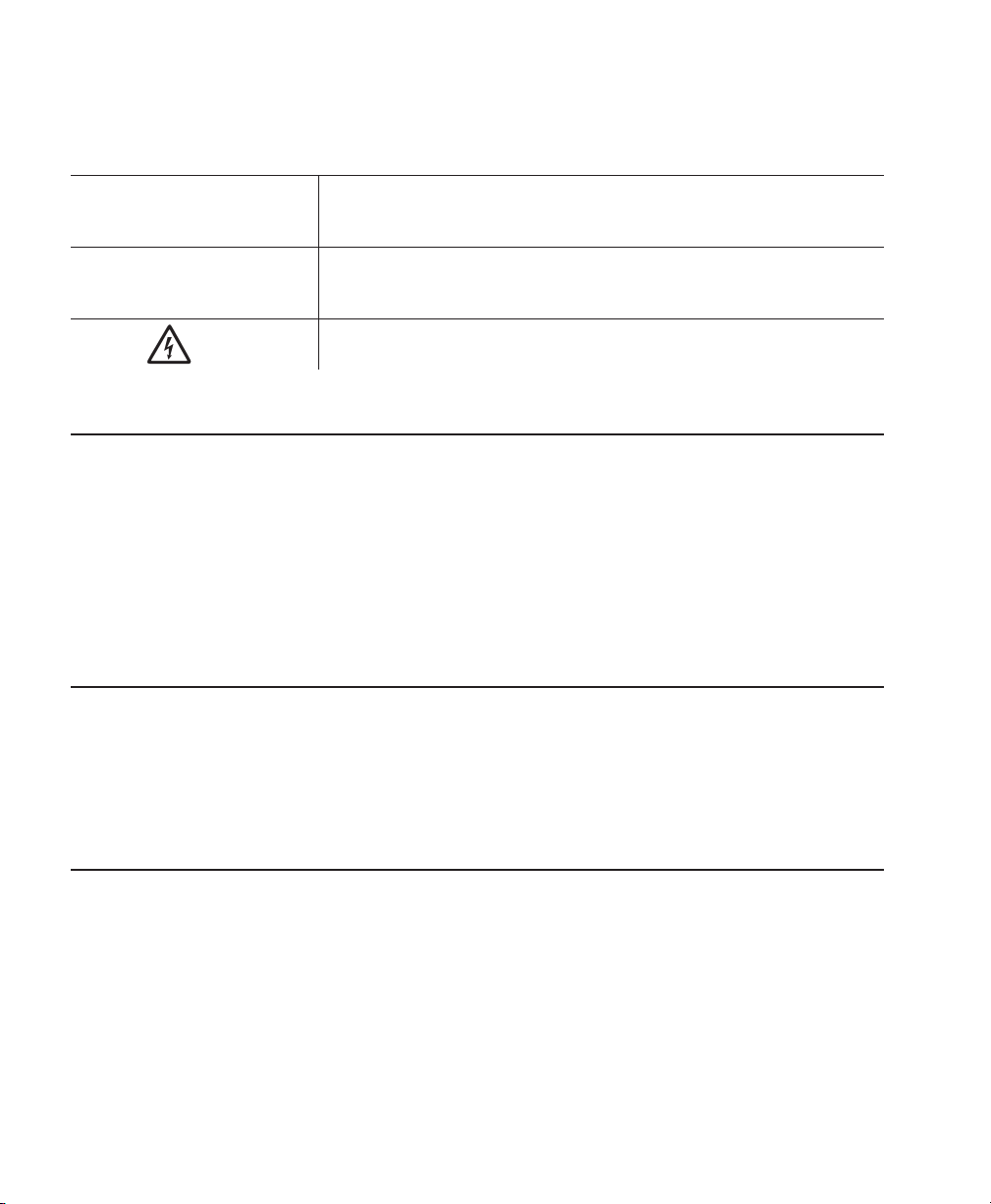
ABOUT THE MWS 2
The Mobile Work Station is shipped assembled. Use this chapter to verify
the cable connections.
Check inside ALL packaging material. Make sure you do not throw away
any pieces. Before using the MWS, remove all packing material from inside
the power cabinet.
Left Side
Front
Right
Side
Back
About the MWS 2-1
Page 10
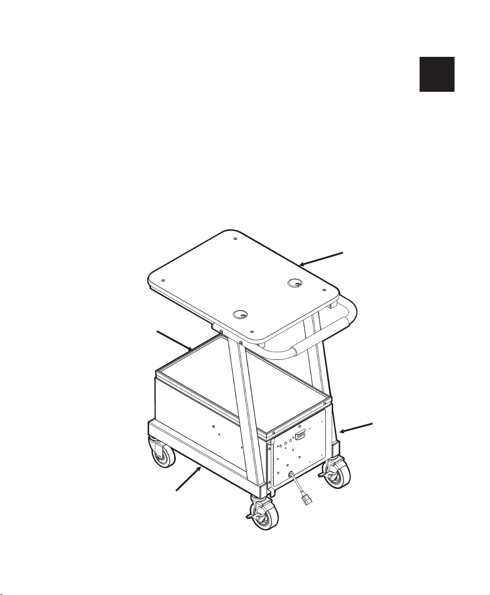
Connecting the Cables
Make sure the charger and battery cables, and power cord are properly
connected. Follow the steps below if you need to connect the cables.
Power cords are not included with International models.
WARNING
Only qualified service personnel may install or replace the
batteries.
1. Using a 5/32-inch (4 mm) Hex key (wrench), open and remove the lid for
the power cabinet.
2. Make sure the power cord (packaged with the battery charger) is
connected to the power socket on the back of the charger.
3. Make sure the battery cable is connected to the socket on the back of
the charger. The cable is keyed.
4. Make sure the voltage selector switch on the back of the charger is set
correctly (115V in U.S.).
Voltage
Selector
Battery
Cable
2-2 About the MWS
Battery
Socket
Power
Socket
Power
Cord
AC Fuse Holder
Page 11
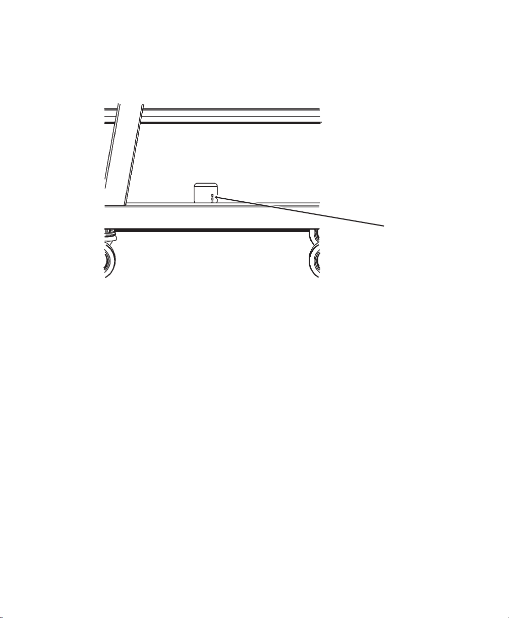
5. The charger’s status lights should be visible through the cut-out in the
left-side panel. See Chapter 3, "Changing the Batteries" for more
information.
Charger
Status LEDs
If not already connected, plug the charger’s power cord into the AC
6.
power outlet inside the power cabinet.
About the MWS 2-3
Page 12
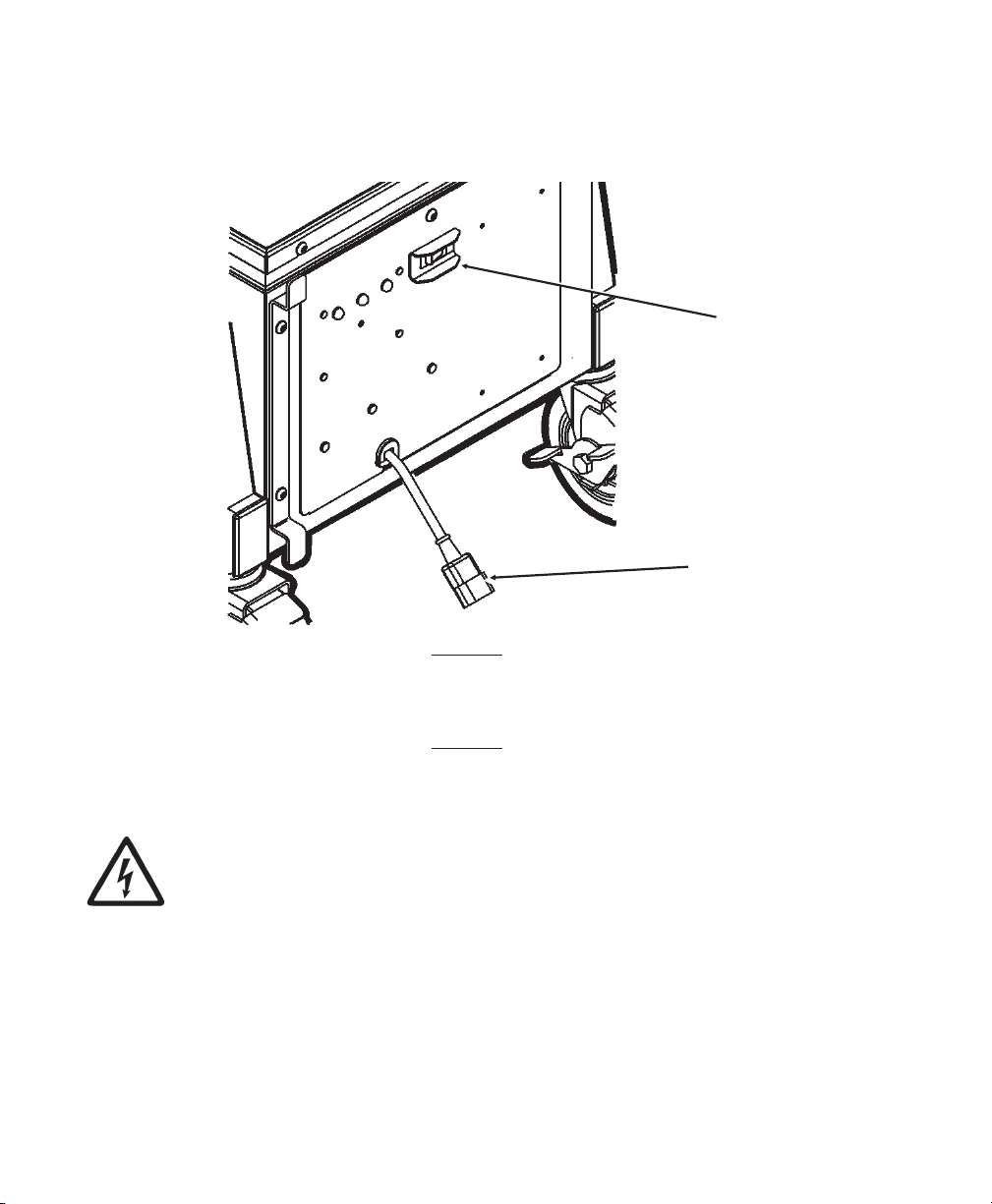
7. Plug the heavy-duty power cord into the external power socket on the
outside panel of the MWS.
MWS Power
Switch
External
Power
Socket
Do Not plug the external power cord into a wall outlet until you are
ready to charge the battery. See Chapter 3, “Charging the Batteries”
for important battery information.
8. Using a 5/32-inch (4 mm) Hex key, replace the lid for the power cabinet.
You may need a power strip inside the power cabinet to provide
AC power to more than one device. Do Not store anything else
inside the power cabinet. The power cabinet must remain
secured at all times and only opened by qualified service
personnel.
2-4 About the MWS
Page 13

Connecting a Printer
Contact your Monarch Representative for instructions on attaching a
Monarch® printer to the MWS.
Using other Monarch® Printers
You can connect Monarch® 9462™ and Monarch® 9465™ chargers to the
MWS. This allows you to keep the chargers close to where you are working
on the sales floor.
The following printers are supported with these chargers:
¨ Monarch® Sierra Sport2™ (9460™)
¨ Monarch® Sierra Sport3™ (9433™)
¨ Monarch® Pathfinder® Ultra® Silver (6032™)
¨ Monarch® Pathfinder® Ultra® Platinum (6039™)
Additionally, a laptop or handheld computer (terminal) can be powered on
the MWS.
About the MWS 2-5
Page 14

Connecting the 9462/9465 Charger
1. Place the charger on the top or bottom shelf.
2. Using a 5/32-inch (4 mm) Hex key (wrench), open and remove the lid for
the power cabinet.
3. Place the charger’s power supply inside the power cabinet.
Thread
Power
Supply Cord
Through
Place Power
Supply Inside
Power Cabinet
Thread the end of the power supply’s cord into the cable tube.
4.
5. Connect the power supply to the charger’s base.
6. Connect the power supply’s cord to AC power outlet inside the power
cabinet.
7. Using a 5/32-inch (4 mm) Hex key, replace the lid for the power cabinet.
8. See Chapter 3, “Charging the Batteries” for more information. For more
information about using your 9462 or 9465 charger, refer to the
Operating Instructions provided with the charger.
Using Other Printers
Contact your Monarch Representative to attach non-Monarch printers to the
MWS.
2-6 About the MWS
Page 15

CHARGING THE BATTERIES 3
This chapter describes how to
¨ charge the batteries
¨ change the fuses.
The battery charger for the MWS is a fully automatic,
maintenance-free charger.
To charge the battery, plug the MWS AC power cord into a grounded outlet.
Charge the battery:
¨ before using the MWS for the first time (charge it for 5
hours)
¨ when the MWS beeps (see “Battery Life” for indications of
low battery conditions)
¨ when the MWS is not in use.
When the MWS is not in use, always leave the battery charger plugged in
and charging. The battery charger is “intelligent;” it monitors the battery
condition and does not overcharge the lead acid battery. Battery life is
extended by frequent charging.
Recycle batteries in accordance with local State, RBRC guidelines, and the
manufacturer’s instructions.
CAUTION
Only qualified service personnel may install or replace the 12-volt
sealed lead-acid non-venting battery. When replacing a battery,
you must use the same type of battery from the same
manufacturer (as the ones provided with the MWS). On 24VDC
models, BOTH batteries MUST be replaced at the same time to
maintain capacity match.
Charging the Batteries 3-1
Page 16

Important Charging Information
WARNING
DANGER! RISK OF ELECTRICAL AND FIRE HAZARD.
CERTAIN ACTIONS MAY RESULT IN DEATH, SERIOUS
INJURY, SHOCK, OR BURNS.
Do Not disassemble the battery charger.
¨
Do Not operate the charger if it has been dropped or otherwise damaged
¨
in any way. Do Not spill liquids into the charger, such as water or soft
drinks.
Do Not expose the battery charger to rain or snow. Never charge a
¨
frozen battery. The colder the battery, the longer it takes to charge.
¨ Plug only into a three-prong grounded outlet. Do Not alter the AC power
cord or plug provided. Do Not operate the battery charger with a
damaged cord or plug.
¨ Do Not let the battery go for a long period in a partly discharged state;
keep it charged.
¨ If using an extension cord, you must use 18 gauge or heavier for lengths
up to 50 feet, or 16 gauge or heavier for lengths up to 100 feet. Use of
improper extension cord could cause fire and/or electric shock. Use an
extension cord bearing the UL listing mark and rated for four Amperes or
greater current capacity.
¨
Pull on the plug rather than the cord when disconnecting the battery
charger. Locate the cords where they will not be stepped on, tripped
over, or otherwise subjected to damage or stress.
¨
The battery must be charged when the total voltage is less than 10.5V
(one battery) or 21V (two batteries). See “Battery Life,” for more
information.
¨
Do Not pry open the sealed lead-acid non-venting battery to add water.
3-2 Charging the Batteries
Page 17

About the Battery Charger
A cut-out in the left-side panel allows viewing of the charger’s status LEDs.
¨ Store the charger in a dry area not subject to prolonged sub-zero
temperatures.
¨ The battery charger is “intelligent;” it monitors the batteries condition
and does not overcharge the batteries. It is recommended to leave the
battery charger plugged in and charging when the MWS is not in use.
Battery life is extended by frequent charging.
¨ The charger’s Power On light is on when all the connections are correct.
¨ The charger’s Green Full Charge light is on when the battery is finished
charging. Leaving the charger connected to the battery and the charger
plugged in prevents the battery from self-discharging.
Important Battery Safety Information
¨ Never smoke or allow a spark or flame in vicinity of battery.
¨ Do Not drop a metal tool on the battery. The resulting spark or
short-circuit on the battery of other electrical part may cause an
explosion.
¨ Remove personal metal items such as rings, bracelets, necklaces, and
watches when working with a lead-acid battery. A lead-acid battery
produces a short-circuit current high enough to weld a ring to metal,
causing a severe burn.
Charging the Batteries 3-3
Page 18

Battery Life
If you leave the battery charger
plugged in and constantly charging
when the MWS is not in use,
the battery life is maximized for the
application. The charger will not
overcharge the batteries.
The MWS has Battery Status
Signal Lights to indicate the battery
status as follows. The following
voltages are nominal (not exact)
and should be used for reference.
Signal
Lights
Flashing Red/
Orange
Warning! The batteries need immediate charging.
Voltage is below 11.25V (one battery) or 22.5V (two
batteries). The MWS beeps (10 seconds beep on and
five minutes no beep) to alert you of this condition.
Flashing Yellow Caution! The batteries are getting low. The voltage is
between 11.25V and 11.75V (one battery) or 22.5V and
23.5V (two batteries).
Flashing Green Go! The voltage is above 11.75V (one battery) or 23.5V
(two batteries). The batteries are charged to
approximately 75% or better capacity.
Immediately plug the power cord into the wall socket and charge
the batteries when you hear a beep/chirp and the signal light
flashes red/orange.
12 Volt switch levels = +/- 0.15V; 24 Volt switch levels = +/- 0.25V
3-4 Charging the Batteries
Page 19

Use the following table to read the charger’s LEDs (indicator lights).
Charger Status
LEDs
LED Status
8-10A
6-8A
4-6A
2-4A
CHARGE
80%
READY
The red lights indicate the charging rate. Deeply
discharged batteries start charging at the 8-10A rate.
As the batteries charge, the charging rate decreases
from 8-10A through 2-4A.
The red light turns on when the charger is connected to
the batteries and the charger has AC power.
Yellow light turns on when the batteries are charged to
80% capacity. The batteries charge to 80 percent in
approximately four hours and can be used at this point.
Green light turns on when the batteries are charged to
full capacity. The batteries charge to full capacity in
approximately three hours from 80 percent. (Total
charging time is approximately seven hours.)
Charging the Batteries 3-5
Page 20

Frequency of Charging/Run-Time Guidelines
The following information is approximate and should be used for
reference. Many factors effect an individual battery’s performance:
¨ the presence of auxiliary devices.
¨ the printing rate (including printhead contrast and number of labels per
day).
¨ the complexity of your printed formats.
¨ the environment (temperature and humidity in your facility).
In the information below, “typical conditions” are defined as follows:
one Monarch® printer printing standard compliance 4x6 labels (5-10
minutes of actual printing per hour), no auxiliary devices attached to the
MWS, and standard environmental conditions (no excessive heat or
humidity).
¨ When using the 12VDC MWS under typical conditions, the battery may
last up to 20 to 50 hours before recharging is necessary.
¨ When using the 24VDC MWS or the 12VDC converter option under
typical conditions, the batteries may last up to 50 to 100 hours before
recharging is necessary.
¨ When using the 24VDC/115VAC MWS with an AC Power Inverter under
typical conditions, the batteries may last up to 48 hours before
recharging is necessary.
¨ When using the 12VDC/115VAC MWS with an AC Power Inverter under
typical conditions, the batteries may last up to 24 hours before
recharging is necessary.
¨ When you notice the batteries need to be charged more frequently, order
replacement batteries. On 24VDC models, BOTH batteries MUST be
replaced at the same time to maintain capacity match.
3-6 Charging the Batteries
Page 21

For example, if you had 60 hours of use between charges and now have 30
hours of use between charges, this is an indication that the batteries need
replacing.
The performance of your batteries varies depending on the
number of printers and/or auxiliary devices, such as a scanner or
terminal, attached to the MWS. Frequent charging of the
batteries is recommended.
Changing Fuses
There are two fuses for the MWS: one connecting the batteries/inverters
and one from BAT2 to the terminal block. Size of the fuses varies
depending on the power option selected when you ordered the MWS.
See Chapter 4, “Power Options,” for more information.
WARNING
You may observe a spark when you make this connection. Do
not make this connection in the presence of Flammable fumes,
explosion or fire may result.
The power switch on the front of the MWS must be off while changing
fuses. (The status light near the power switch should be OFF.)
1. Turn off the MWS power supply and unplug the power cord.
2. Using a 5/32-inch (4 mm) Hex key (wrench), open and remove the lid for
the power cabinet.
3. Unplug the fuses from the fuse holders.
Charging the Batteries 3-7
Page 22

4. Insert the proper voltage fuse in each fuse holder. Each fuse is labeled
as 20A, 30A, 50A, or 80A.
Fuse Description
F1 20 A ATO (from BAT2 to the terminal block)
F2 20 A ATO (connects the batteries only for the DC power option)
30 A ATO (for the 300W, 24VDC Power Inverter option)
50 A Maxifuse (for 300W, 12VDC Power Inverter option)
80 A Maxifuse (for 1000W, 24VDC Power Inverter option)
5. Using a 5/32-inch (4 mm) Hex key, replace the lid for the power cabinet.
About the Charger’s Fuse
The charger (12V or 24V) inside the MWS also has a fuse:
T4A 125V fuse (for 12V chargers) or T6A 125V fuse (for 24V chargers).
3-8 Charging the Batteries
Page 23

POWER OPTIONS 4
Your MWS was ordered with one of these power options:
¨ 12VDC/115VAC 300W AC Power Inverter
¨ 24VDC/DC/DC Converter (12VDC out)
¨ 24VDC/115VAC 300W AC Power Inverter
¨ 24VDC/115VAC 1000W AC Power Inverter
Make sure all packing material is removed from the power cabinet before
use.
Keep the MWS power switch ON when in use. If the
MWS will be unused for extended periods of time,
turn OFF the MWS power switch.
The MWS power switch controls the power to all printers. If using more
than one printer on the MWS, manually turn OFF each printer’s power
switch.
Power Options 4-1
Page 24

About the Inverter
The power inverter is only 115V. The AC power inverter uses battery
power, which may require more frequent charging of the batteries.
The AC power inverter provides 115V power to peripherals, such as a PC,
scanner, charger, or printer.
WARNINGS
¨ This equipment contains components which can produce arcs or sparks.
To prevent fire or explosion, do not install near Flammable materials or
in locations that require ignition-protected equipment (including
gasoline-powered machinery, fuel tanks, joints, or fittings).
¨ The inverter is designed to operate from a battery. Performance cannot
be guaranteed and damage can result when the inverter is used
without the batteries installed!
¨ Even if the MWS is not connected to an outlet, power is still supplied to
the inverter from the batteries and charger. Therefore, all harnesses
are always “live.”
¨ You may observe a spark when you make this connection. Do not make
this connection in the presence of Flammable fumes, explosion or fire
may result. Operation of the inverter without a proper ground connection
may result in an electrical safety hazard.
¨ Remove ALL fuses from the harnesses before connecting ANY
harnesses to the batteries or switch.
4-2 Power Options
Page 25

You may need a UL/CSA listed power strip inside the power
cabinet to provide AC power to more than one device. Do Not
store anything else inside the power cabinet. The power cabinet
must remain secured at all times and only opened by qualified
service personnel.
300W/1000W Inverter LED Status
Display Input Voltage
LED Status DC 12V DC 24VC
GREEN (solid) AC Power OK AC Power OK
RED Blink (fast)
Over-voltage protect
RED Blink (slow)
under-voltage protect
RED Blink (intermittent)
over-temperature protect
RED (solid)
over-load protect
15.3 30.6
10.5 21.0
_ _
>400W >400W / 960W
Power Options 4-3
Page 26

Using the Remote Switch
The MWS On/Off switch should be used as a remote switch to turn the
inverter ON or OFF. If ordered with the inverter option, your MWS comes
preset to use the remote switch. However, if you notice the inverter stays
ON all the time, check this setting. The switch may have been bumped
while replacing a battery.
1. Using a 5/32-inch (4 mm) Hex key (wrench), open and remove the lid for
the power cabinet.
2. On the inverter’s front panel, set the ON/OFF/REMO switch to OFF or
REMO (remote).
Set to OFF or REMO
300 Watt Inverter
3. Make sure the switch on the MWS electrical panel is OFF.
4. Using a 5/32-inch (4 mm) Hex key, replace the lid for the power cabinet.
4-4 Power Options
Page 27

PRINTING 5
To print supplies from a Monarch® 9825ä or 9855ä printer on the MWS:
1. Turn on the MWS power supply and turn on the printer.
You will see
PRINT MODE
Ready B
2. Press Feed/Cut to calibrate the supply. You are now ready to
print.
To conserve the battery, make sure the MWS power switch is turned OFF
when not in use OR when charging the batteries. For optimal (shortest)
charging time, turn off the MWS and printer while charging.
¨ If you need to finish a batch, you can print while charging, as long as the
batteries are not too depleted. However, printing while charging is not
recommended on a frequent basis.
¨ If the printer will be unused for extended periods of time, we recommend
leaving the printhead unlatched.
¨ If the printer’s green power light blinks, you need to recharge the battery.
There is a small reserve of battery power to continue printing after the
green power light begins blinking.
¨ You must recharge the battery when you see error 762 or “Battery Dead”
on the display because the printer is in a “lock-up” condition and does
not print until the battery is recharged.
¨ The printer may slow down if the battery voltage drops below a certain
level. The printer continues to print at the reduced speed until the
batteries are charged and the printer is turned off and then back on.
See “Battery Life” in Chapter 3 for more information about charging the
batteries.
Printing 5-1
Page 28

About Sleep Mode
If the Monarch® 9800ä printer is inactive for longer than 30 seconds, the
printer goes into sleep mode to conserve battery power. While in sleep
mode, the display backlight is turned off to conserve battery power. Once
the printer “wakes up,” the backlight turns on.
To “wake up” the printer, press any button on the control panel. The buttons
are active during sleep mode, so if you press Escape/Clear, the printer
“wakes up” and you enter the offline menu mode. You can also send any
data to the printer to wake it up. You do not lose any data sent to the
printer during sleep mode.
5-2 Printing
Page 29

SPECIFICATIONS A
Mobile Work Station (MWS)
Height: Approximately 37 inches (940 mm)
depending on selected options
Top Width: 20 inches (508 mm)
Wheel Base: 18.5 inches (470 mm)
Length: 31.5 inches (800 mm)
Power Cabinet
Lower Shelf:
Top Shelf :
(Solid Top)
Weight: Approximately 125 lbs (57 kg)
Operating Limits 40°F to 95°F (5°C to 43°C) with thermal
Storage: 15°F to 120°F (-9°C to 49°C)
Humidity: 5% to 90% non-condensing
15 inches wide x 25.5 inches long
(381 mm x 648 mm)
20 inches wide x 26 inches long
(508 mm x 660 mm)
depending on selected options
transfer supplies
Specifications A-1
Page 30

Batteries
¨ (1) 12-volt, 55 amp-hours, deep cycle battery
¨ (2) 12-volt, 55 amp-hours, deep cycle batteries
¨ Sealed lead-acid, non-venting (safety venting only), no
transportation restrictions
¨ Shelf Life/Charge Retention:
1 month 97%
3 months 91%
6 months 85%
¨ Cycle Use:
100% depth of discharge approx. 250 cycles
50% depth of discharge approx. 550 cycles
30% depth of discharge approx. 1200 cycles
Cycle Life is approximate and many factors effect an individual battery’s
performance.
Chargers
12VDC Models
Input 117VAC +/- 10% (60Hz), 220 VA (Volt Amps)
IEC connection
Output 12 Volts, 10 Amps DC
¨ Reverse polarity and short circuit-proof
¨ Temperature compensated
¨ Low voltage start (total battery voltage must be greater than 1V to
charge)
¨ 3-Stage charging for deep cycle 12-volt lead-acid battery
A-2 Specifications
Page 31

24VDC Models
Input 117VAC 60Hz, 320 VA (Volt Amps)
IEC connection
Output 24 Volts, 8 Amps DC
¨ Reverse polarity and short circuit-proof
¨ Temperature compensated
¨ Low voltage start (greater than 1V to charge)
¨ 3-Stage charging for deep cycle 12-volt lead-acid battery
(2 in series)
Usw onlyNRTL-listed (National Recognized testing Lab)
accessories.
300W Inverter
Input Voltage 10.5 to 15VDC (12V)
21 to 30VDC (24V)
No Load Current 0.26A (12V)
0.23A (24V)
Frequency 50/60 Hz ± 0.3%
Output Voltage 110VAC ± 5%
Output Power 300W RMS (continuous)
Surge Power 400W RMS (1 second)
Output Waveform Pure Sine Wave (THD <4%)
Efficiency
(Full Load / Max.)
Operating
Temperature
72% (12V)
78% (24V)
32°F to 105°F (0°C to 40°C)
Specifications A-3
Page 32

1000W Inverter
Input Voltage 21 to 30VDC (24V)
No Load Current 0.75A
Frequency
(Switch Selected)
Output Voltage 110VAC +-5%
Output Power 1000W RMS (continuous)
Surge Power 2000W RMS (1 second)
Output Waveform Pure Sine Wave (THD <3%)
Efficiency
(Full Load / Max.)
Operating
Temperature
50/60 Hz ± 0.05%
92%
32°F to 105°F (0°C to 40°C)
A-4 Specifications
Page 33

WIRING DIAGRAMS B
This appendix contains wiring diagrams for the various power options:
¨ 12VDC/115VAC 300W AC Power Inverter
¨ 24VDC/DC/DC Converter (12VDC out)
¨ 24VDC/115VAC 300W AC Power Inverter
¨ 24VDC/115VAC 1000W AC Power Inverter
WARNING
Only qualified service personnel may install or replace the
12-volt sealed lead-acid non-venting battery.
When replacing a battery, you must use the same type of battery from
the same manufacturer (as the ones provided with the MWS). On 24VDC
models, BOTH batteries MUST be replaced at the same time to maintain
capacity match.
One or two power sparks may occur (this is normal) when installing or
changing the fuses.
Wiring Diagrams B-1
Page 34

12VDC/115VAC 300W AC Power Inverter
B-2 Wiring Diagrams
Page 35

24VDC/DC/DC Converter (12VDC Out)
Wiring Diagrams B-3
Page 36

24VDC/115VAC 300 Watt Power Inverter
B-4 Wiring Diagrams
Page 37

24VDC/115VAC 1000 Watt Power Inverter
Batt. #2
PART#
126523
55Ah
CHARGER
24 Volt
PART# 126803
+24V
TERM. BLCK
GND
80
AMP
MAXIE
fuse
24V_SW
+ -
20
AMP
ATO
fuse
RMT
GND
INVERTER
1000 WATT
#126800
+
-
1
2
3
END VIEW:
MALE XLR CONNECTOR
PIN #1- DC OUPUT "+"
PIN #2- DC OUTPUT "-"
XLR
CONNECTORS
FEMALE
MALE
Batt. #1
PART#
126523
55Ah
SWITCH
#124828
BATTERY STATUS
BOARD 126473-24
126777 GND
HARNESS BATTERY
126679
JUMPER
126679
JUMPE
R
126761
BATTERY STATUS BD HARNESS
126762
HARNESS,
FUSED 20A
MAIN (F1)
126776
MAIN PWR-
MINUS
127132
127132
127131
4 AWG WIRE
BLK
127148
BATTERY JUMPER
CONNECT W/80A
FUSE (F2)
126767
NOT
USED
126980
HARNESS
CHARGER
127130
4 AWG WIRE
RED
REMOTE HARNESS, RJ45 TO .25
QUICKCONNECT
127132
Wiring Diagrams B-5
Page 38

Visit www.paxar.com for sales, service,
supplies, information, and telephone numbers
for our locations throughout the world.
TOLL FREE:
1-800-543-6650 (In the U.S.A.)
1-800-363-7525 (In Canada)
 Loading...