

Paxar 9662 User Manual
Model
9662
Printer
USER MANUAL
CONFIDENTIAL

Checking Your Box
Receiving the box of your printer, you are advised to
check first for the possible shipping damage. There are two ways you
can do it:
1. Inspect the outer appearances of both the box and the printer for
Printer
Power Cord
User's
Manual
CD ROM
Ribbon
possible damage.
2. Raise the top cover of the printer to see if the media compartments
are in order.
If damages did occur, immediately file the claim to the shipping
company for settlement.
Having performed the primary inspections, next step,
please check whether you have received the following accessories
together with the printer. If there is any item missing, contact your local
dealer to get it.
1
2

Power Supply
Setting up the Printer
Before setting up the printer you should first consider the following:
♦
♦
♦
Find a solid flat surface with adequate room for the printer. Make
sure there is enough room on the top side for the media and ribbon
access.
The location should be near the host or terminal. Consider the
distance between host and printer for the communication cable
(serial or parallel cable)
Clear the ground and isolate from other electrical cables for the
power adapter.
Connecting the Power Cord
1. Leave the power switch at the ”O” position.
2. Connect the power supply plug to the power jack and the other
end to your AC source.
4
AC Electrical Outlet
Power Jack
AC Power Connector
Power Switch
3
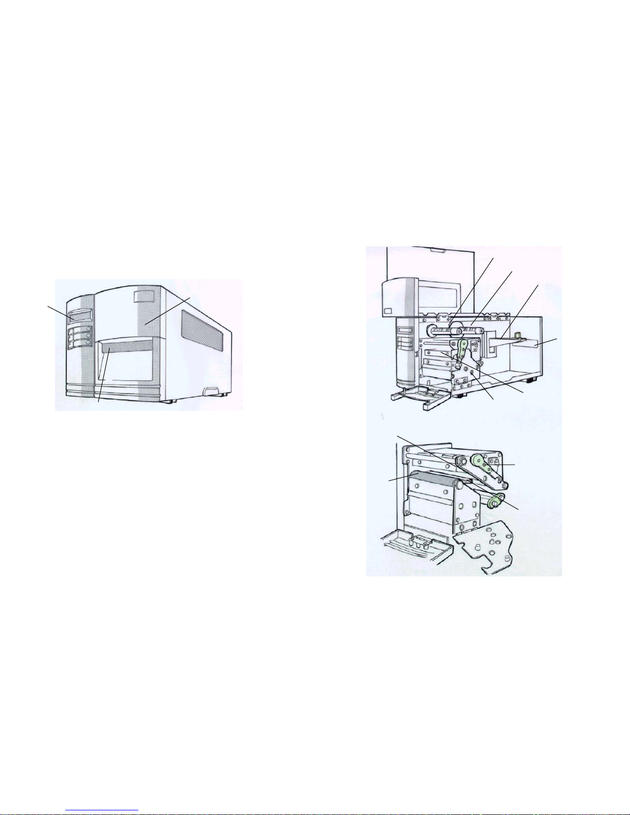
Parts and Features
LCD Display
Top Access Door
Front Access Doo
r
6
Head Latch
Paper Sensor
Guide
Platen Roller
Thermal Print Head
Thermal Print Head
Bracket
Feed Slot
Ribbon Supply Spindle
Media Supply Spindle
Ribbon Pick-up Spindle
5
Loading the Ribbon
Rewinder
Notes:
Peeler
Sensor
1. This section is applicable to the transfer thermal printing.
2. Attached ribbon is coating inside.
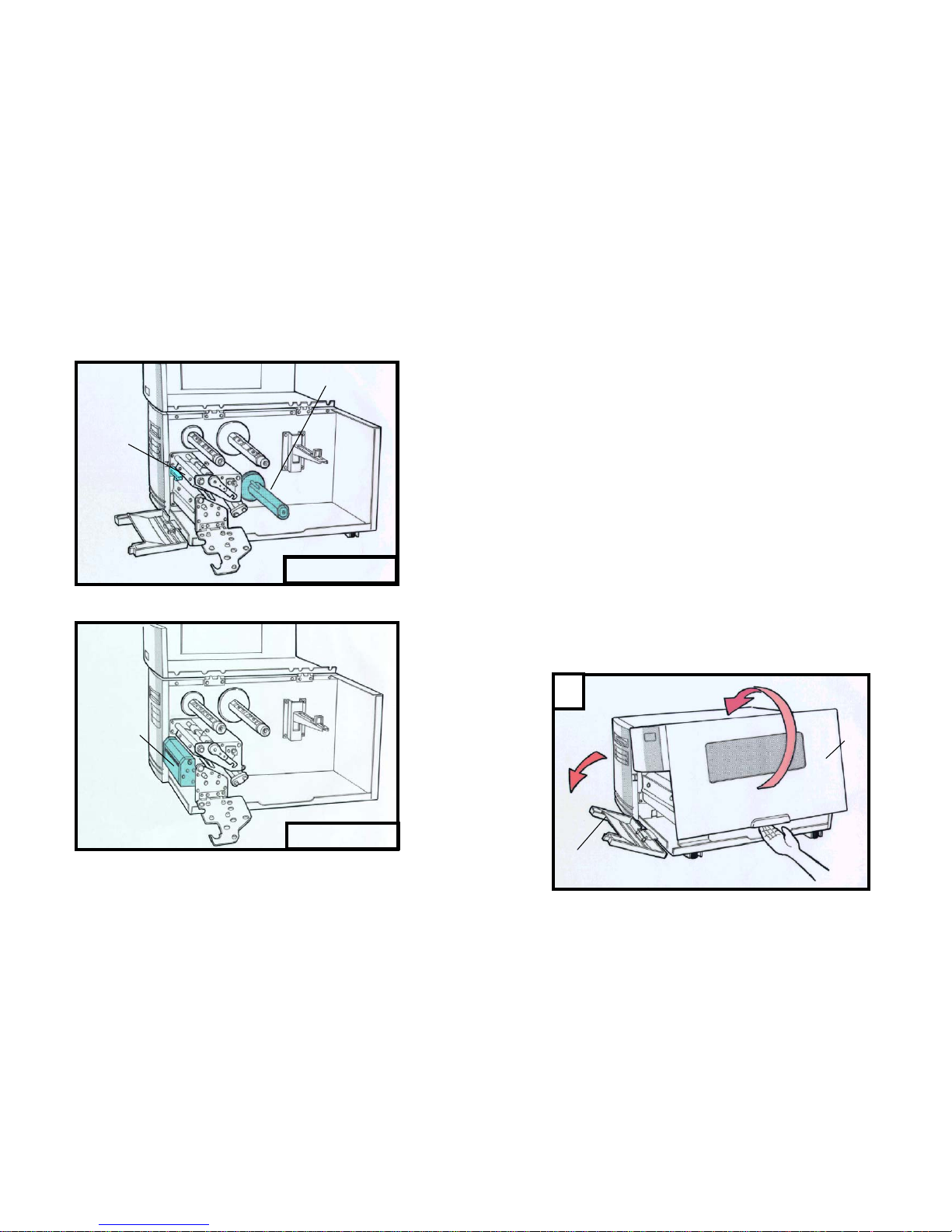
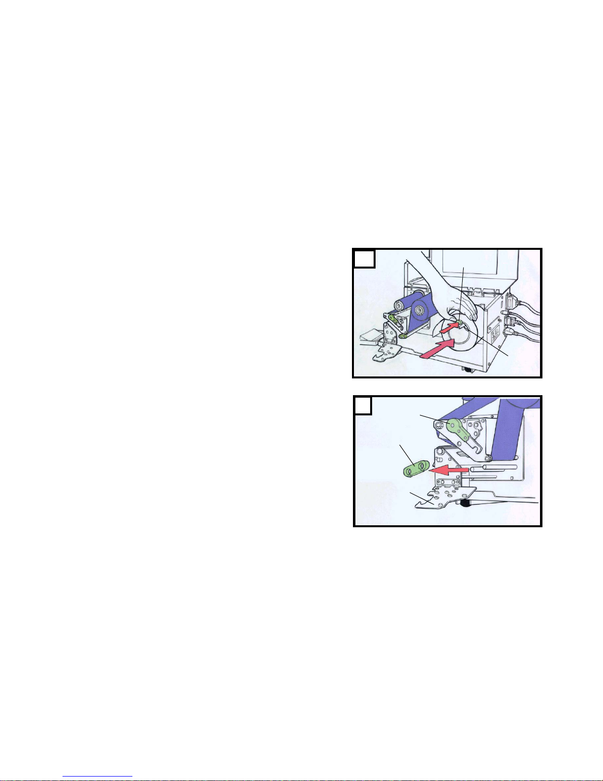
1. Lift the top access door and the front access door to expose the
compartment. ( Figure 1 )
2. Push the head latch by anti-clockwise, and then fold the bracket.
( Figure 2 )
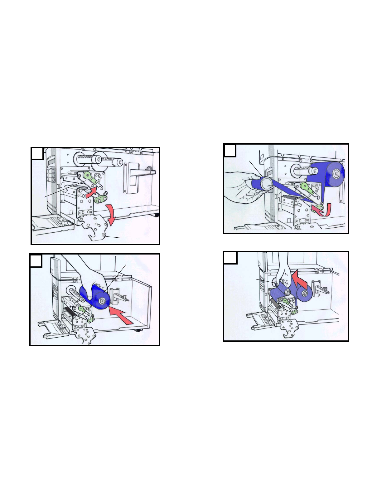
3. Unwrap the ribbon roll pack and separate the ribbon roll and the bare
core.
4. Insert the ribbon roll into the ribbon supply spindle. ( Figure 3 )
5. Lead the bare core through the print head module. ( Figure 4 )
Peel Off Mode
6. Attach the edge of the ribbon on the bare core and wind it a little bit
onto the core.
Note:
The dull side of the ribbon should be faced down.
7. Insert the bare core into the ribbon pick-up spindle. ( Figure 5 )
8. Turn the pick-up spindle to ensure the ribbon is tightly wound.
Cutter Mode
Cutter
8
Top Cover
Front Access
1
Door
7
Bracket
Head
Latch
2
Ribbon Supply
Spindle
3
10
Bare Core
Print Head Module
Ribbon Pick-up
Spindle
5
4
9
Bracket
Outside Media
Guide
Head Latch
Media Supply
Spindle
Media Guide
Loading the Media
9662 Series printers can be operated in three different options: standard,
peel-off, or with a cutter.
Standard mode allows you to collect each label freely.
In peel-off mode, the backing material is being peeled away from
the label as it is printed. After the former label is removed, the next
one will be printed.
In cutter mode, the printer automatically cuts the label after it is
printed.
Standard Mode
1. Insert the media roll into the media supply spindle and move the
media guide to the inside. ( Figure 6 )
2. Push the head latch by anti-clockwise, and then fold the bracket.
3. Remove the outside media guide. ( Figure 7 )
1.Lead the Media through the print head module and under the paper
sensor guide. ( Figure 8 )
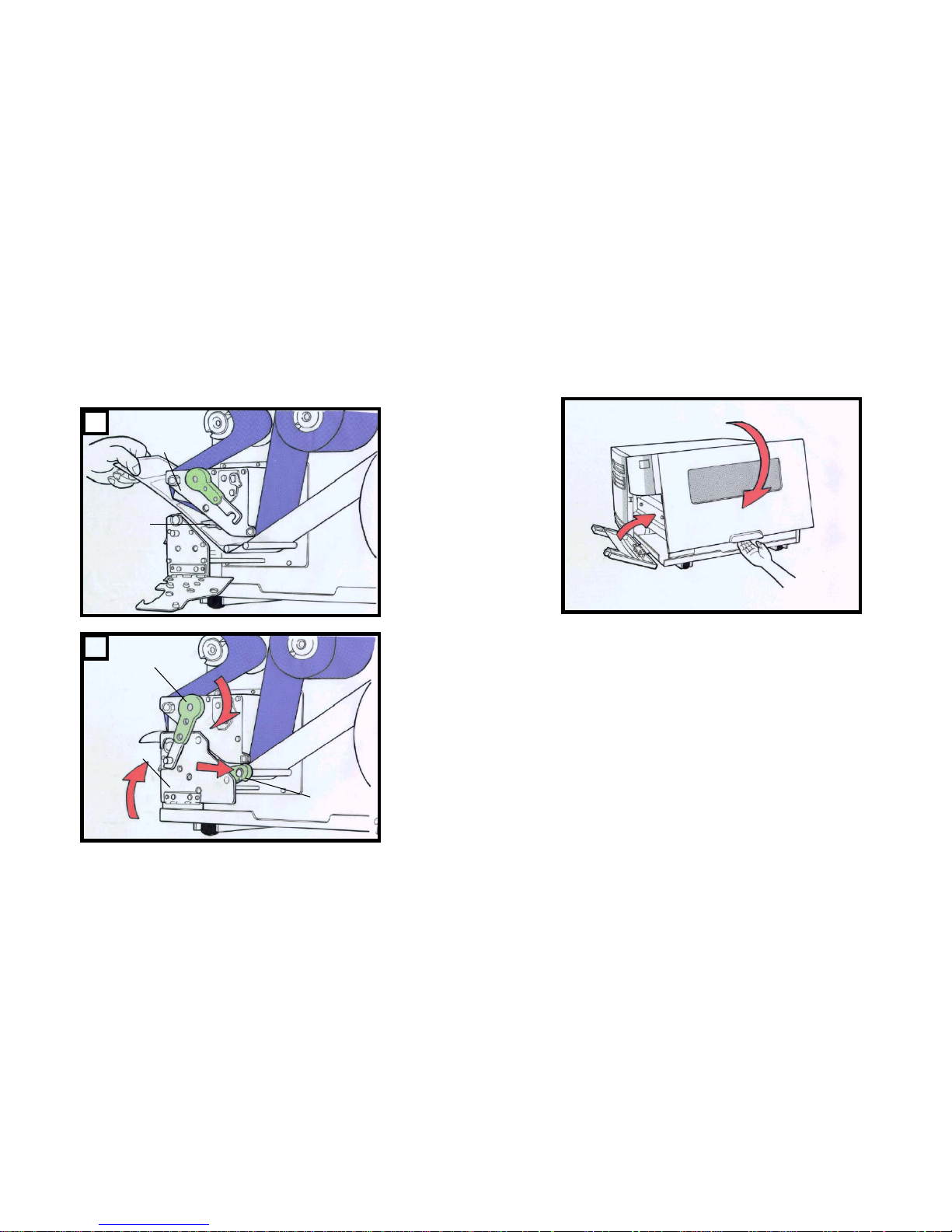
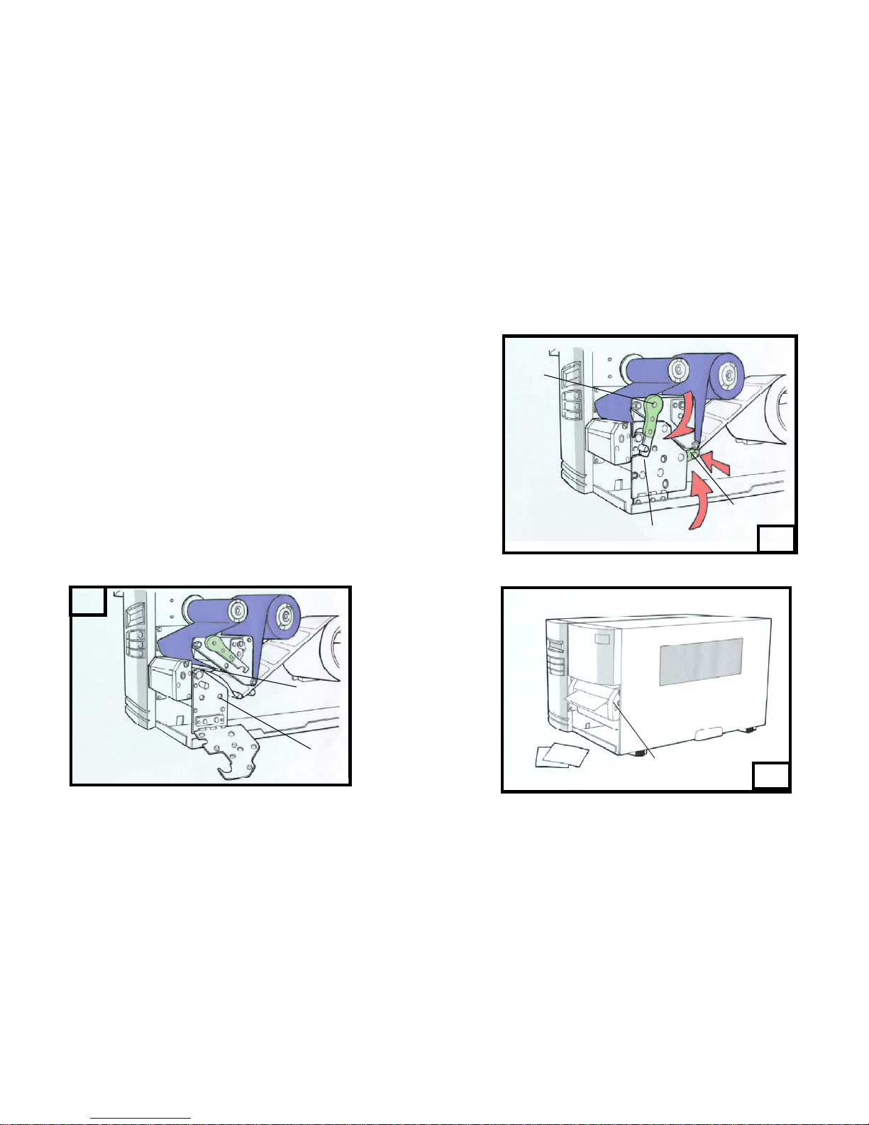
5. Put back the outside media guide, close the bracket, and buckle the
head latch. ( Figure 9 )
6. Close the top access door and the front access door and then turn
on the printer or press the “FEED” button if the printer is already on
( Figure 10 )
11
12
Print Head
Paper Sensor
8
9
Head Latch
Bracket
Outside Media Guide
13
14
Peel Off Mode
Follow the common procedure of “ Loading the Media “ of Standard
Mode from step 1 to 3.
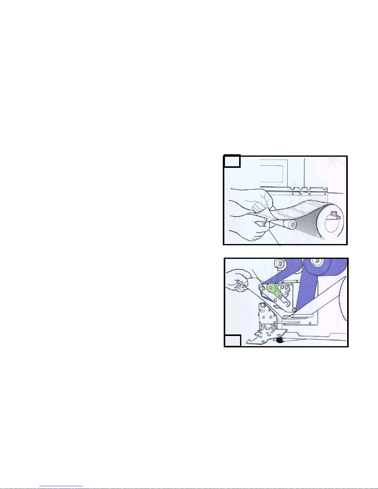
4. Remove approximately 6” long labels from the label
backing paper. ( Figure 11 )
5. Lead the backing paper through the print head module. ( Figure 12 )
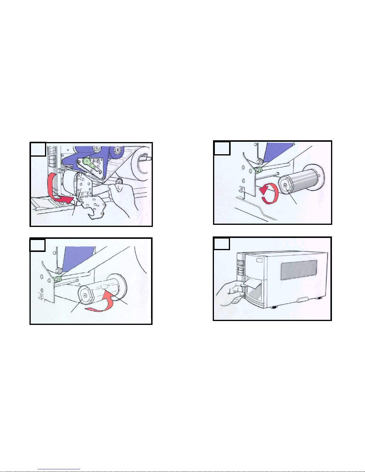
6. Turn back under the print head module. ( Figure 13 )
7. Use a sticker to fix the media on the rewinder kit.( Figure 14 )
8. Turn the rewinder kit twice to ensure the media is firmly fixed. ( Figure
15 )
9. Close the side access door and turn on the printer or press the FEED
button if the printer is already on. ( Figure 16 )
Notes:
1. The “ FEED “ button will not drive the printer to peel. The peeling work
can be executed only when (1 ) the software setting is ready; (2) Bit 5
of DIP switch at rear panel must be set to ON position.
2. Please sure the peeler sensor is out of ribbon path when it’s installed.
16
11
Backing Paper
12
Print Head Module
15
15
13
Rewinder Kit
Print Head Module
16
14
Sticker
Rewinder Kit
17
18
Cutter Mode
Follow the common procedure of “ Loading the Media “ of Standard
Mode from step 1 to 3.
4. Insert the media into the print head module and under the paper
sensor guide. ( Figure 17 )
5. Put back the outside media guide, close the bracket, and buckle the
head latch. ( Figure 18 )
6. Close the top access door and turn on the printer or press the FEED
button if the printer is already on, and then the label will be fed into the
cutter mode automatically. ( Figure 19 )
Note:
The “ FEED “ button will not drive the printer to cut. The cutting work can
be executed only when (1) the software setting is ready; (2) Bit 3 of DIP
switch at rear panel must be set to the ON position.
17
Paper Sensor Guide
Print Head Module
20
Head
Latch
18
Outside Media
Guide
19
Bracket
Cutter
19
 Loading...