

Page 1
TM
Monarch
9476
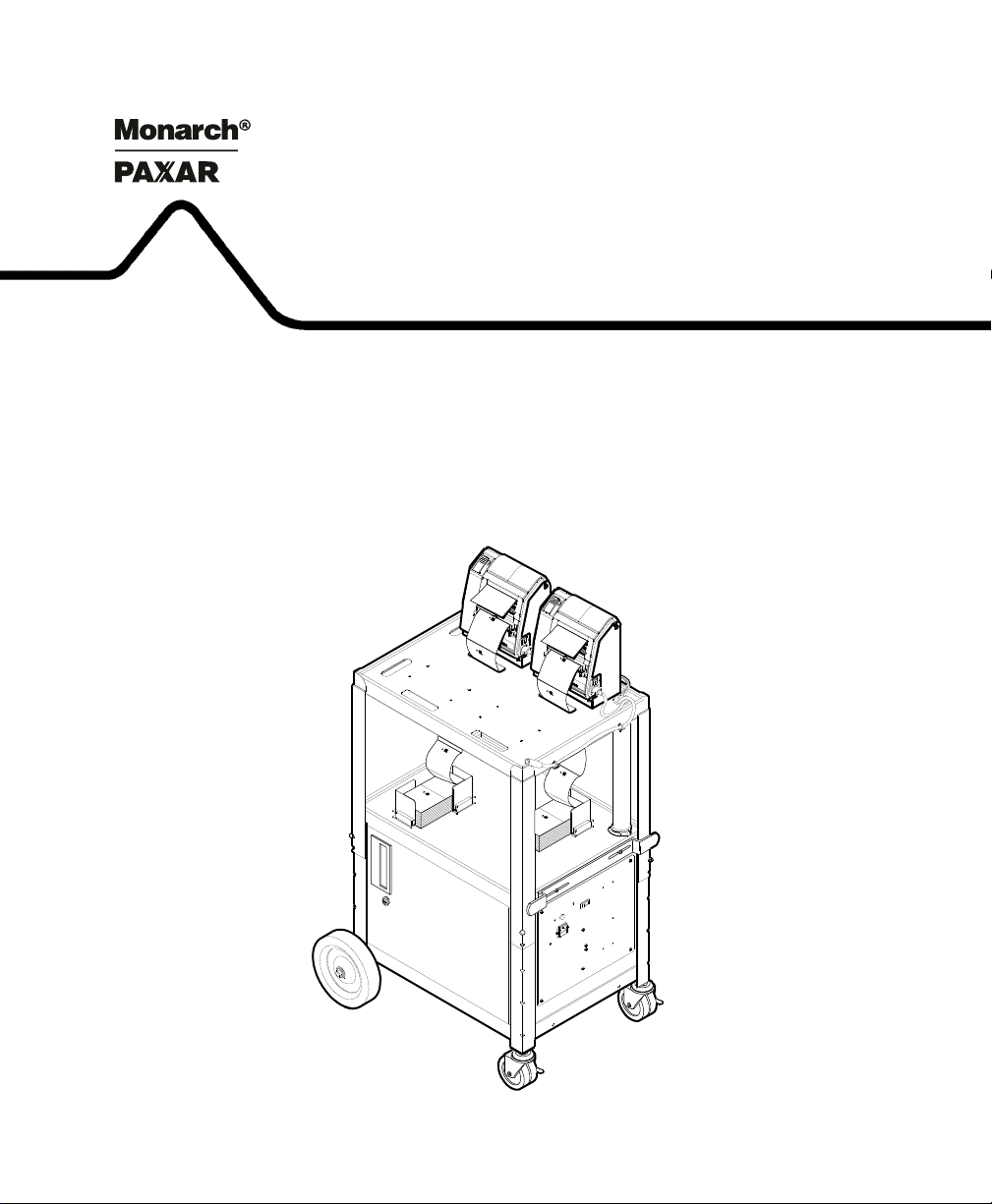
Mobile Printing Station
Assembly and Setup
Instructions
TM
TC9476OI Rev. AA 4/99 ©1995 Monarch Marking Systems, Inc. All rights reserved.
Page 2

Each product and program carries a respective written warranty, the only warranty on
which the customer can rely. Monarch reserves the right to make changes in the
product, the programs, and their availability at any time and without notice. Although
Monarch has made every effort to provide complete and accurate information in this
manual, Monarch shall not be liable for any omissions or inaccuracies. Any update
will be incorporated in a later edition of this manual.
©1995 Monarch Marking Systems, Inc. All rights reserved. No part of this
publication may be reproduced, transmitted, stored in a retrieval system, or
translated into any language in any form by any means, without the written
permission of Monarch Marking Systems, Inc.
WARNING
This equipment has been tested and found to comply with the limits for a Class A digital
device, pursuant to Part 15 of the FCC Rules. These limits are designed to provide
reasonable protection against harmful interference when the equipment is operated in
a commercial environment. This equipment generates, uses, and can radiate radio
frequency energy and, if not installed and used in accordance with the instruction
manual, may cause harmful interference to radio communications. Operation of this
equipment in a residential area is likely to cause harmful interference in which case the
user will be required to correct the interference at his own expense.
CANADIAN D.O.C. WARNING
This digital apparatus does not exceed the Class A limits for radio noise emissions from
digital apparatus set out in the Radio Interference Regulations of the Canadian
Department of Communications.
Le présent appareil numérique n’émet pas de bruits radioélectriques dépassant les
limites applicables aux appareils numériques de la classe A prescrites dans le
Réglement sur le brouillage radioélectrique édicte par le ministère des Communications
du Canada.
9476 and 9490 are trademarks and Monarch is a registered trademark of Monarch Marking Systems, Inc.
Paxar is a trademark of Paxar Corporation.
Monarch Marking Systems
P.O. Box 608
Dayton, Ohio 45401
Page 3

Preface
The Monarch 9476 Mobile Printing Station, or "the Station,"
allows you to mobilize and use up to four Monarch
printers. The 12-volt battery stored in the Station powers the
printers. A portable data collection device or portable PC
sends the data to the printers through a single, shared
communication cable.
This document describes how to
F assemble the Station
F install the printers
F load fan-fold supplies
F charge the Station’s battery.
®
9490
Audience ------------------------------------------------------------------------------------------------------
This manual is designed for the person assembling the Station
and setting it up to print supplies.
w
Only qualified service personnel may install or replace the
12-volt battery for the Station.
Service personnel should have appropriate technical training
and experience necessary to:
F install or replace a 12-volt battery
F be aware of hazards to which they are exposed in
installing or replacing the battery, and of measures to
minimize the danger to themselves or other persons.
i
Page 4

9476 Assembly and Setup Instructions
Other Documentation ------------------------------------------------------------------------------
To send data to the printers and print labels or tags, see the
following additional manuals:
To: See:
create online packets to
send data to the printer
F define an online
address for a printer
F select a printer on the
Station to receive online
packets
F select printer voltage
F load ribbon
F troubleshoot printers
F solve printer problems
MPCLII Packet Reference Manual
(TCMPCL2PM)
Addressing a Monarch 9490
Printer (TCMPCLIDAD)
9490 Operator’s Handbook
(TC9490OH)
ii
Page 5

Table of Contents
Chapter 1. Assembling the Station . . . . . . . . . . . . . . . . . . . . . . 1-1
Parts List. . . . . . . . . . . . . . . . . . . . . . . . . . . . . . . . . . . . . . . 1-1
Tools You Need. . . . . . . . . . . . . . . . . . . . . . . . . . . . . . . . . . 1-3
Step 1: Attaching the Wheels and Casters . . . . . . . . . . . . 1-3
Step 2: Adjusting the Station’s Height . . . . . . . . . . . . . . . . 1-6
Step 3: Attaching the Cabinet Handle and Cord Bracket. . 1-7
Step 4: Attaching Optional Items . . . . . . . . . . . . . . . . . . . . 1-8
Attach the Push Handle . . . . . . . . . . . . . . . . . . . . . 1-9
Attach the Drop Shelf . . . . . . . . . . . . . . . . . . . . . . 1-10
Attach the Data Entry Terminal Cradle . . . . . . . . . 1-13
Step 5: Installing the Battery and Charger. . . . . . . . . . . . 1-14
Install the Battery . . . . . . . . . . . . . . . . . . . . . . . . . 1-14
Install the Battery Charger . . . . . . . . . . . . . . . . . . 1-18
Step 6: Installing the Printers. . . . . . . . . . . . . . . . . . . . . . 1-22
Attach the Printer Brackets . . . . . . . . . . . . . . . . . . 1-22
Attach the Printers. . . . . . . . . . . . . . . . . . . . . . . . . 1-23
Chapter 2. Loading Supplies . . . . . . . . . . . . . . . . . . . . . . . . . . . 2-1
Loading Fan-Fold Supplies . . . . . . . . . . . . . . . . . . . . . . . . . 2-3
Loading Roll Supplies in Fan-Fold Printers. . . . . . . . . . . . . 2-9
Loading Ribbon. . . . . . . . . . . . . . . . . . . . . . . . . . . . . . . . . 2-14
Reloading a Ribbon Cassette . . . . . . . . . . . . . . . . . . . . . . 2-15
Printing . . . . . . . . . . . . . . . . . . . . . . . . . . . . . . . . . . . . . . . 2-17
Chapter 3. Charging the Battery. . . . . . . . . . . . . . . . . . . . . . . . . 3-1
Important Charging Information . . . . . . . . . . . . . . . . . . . . . 3-2
Battery Life . . . . . . . . . . . . . . . . . . . . . . . . . . . . . . . . . . . . . 3-3
iii
Page 6

9476 Assembly and Setup Instructions
Chapter 4. Troubleshooting . . . . . . . . . . . . . . . . . . . . . . . . . . . . 4-1
Solving Problems . . . . . . . . . . . . . . . . . . . . . . . . . . . . . . . . 4-1
Changing Fuses . . . . . . . . . . . . . . . . . . . . . . . . . . . . . . . . . 4-2
Changing the Battery Fuse . . . . . . . . . . . . . . . . . . . 4-2
Changing the AC Fuse . . . . . . . . . . . . . . . . . . . . . . 4-4
Chapter 5. Specifications . . . . . . . . . . . . . . . . . . . . . . . . . . . . . . 5-1
Utility Cart . . . . . . . . . . . . . . . . . . . . . . . . . . . . . . . . . . . . . 5-1
Battery . . . . . . . . . . . . . . . . . . . . . . . . . . . . . . . . . . . . . . . . 5-1
Charger . . . . . . . . . . . . . . . . . . . . . . . . . . . . . . . . . . . . . . . 5-3
iv
Page 7

Chapter 1. Assembling the Station
This chapter describes how to assemble the Station and install
the battery, battery charger, printers, and optional items.
Parts List ----------------------------------------------------------------------------------------------------
Make sure you received the listed quantity of the following
parts. Check all internal cartons and packaging for these
parts. A ruler is shown to help you identify screws and bolts.
nThis list does not include parts for optional items. See
"Attaching Optional Items" for a list of these parts.
General Cart Packaging
Packaged separately: Package #1:
F (1) utility cart F (2) large washers
F (1) axle F (2) axle end caps
F (2) axle mounts F (1) chrome handle insert
F (2) axle end caps F (4) 1/4"-20 wing nuts (black)
F (1) heavy duty power cord F (2) 5/8" phillips screws
(black)
F (2) 4" casters with brakes F (2) M3.5 washers
F (1) plastic cable-tube and
clamp
F (2) keys (in envelope)
F (4) 1/4"-20 x 3/4" slotted
bolts (black)
1-1
Page 8

9476 Assembly and Setup Instructions
Package #2: Inside Cart:
F (2) 8-32 nuts/
F (1) green wire (inside cart)
lockwashers (black)
F (2) 8-32 x 1/2" slotted
screws (black)
F (1) cord bracket F (1) battery harness cable
F (1) host input cable (encased
in cable tube)
Package #3
F (2) 8" wheels
Battery and Charger Packaging:
F (4) retainer rods F (1) battery charger
F (2-8) supply holder
brackets with magnets
F (1) power cord (packaged
F (2) universal battery
hold-down rubber brackets
in charger carton)
Package #1
F (1) rechargeable 12-volt
battery
F (3 ) M5 lock washers
F (2) M5 x 15mm phillips/hex
bolts
1-2
Package #2
F (4) 1/4"-20 wing nuts F (4) 1/4"-20 lock washers
F (2) M5 washers F (4) 1/4"-20 washers
F (2) M5 nuts F (1) M5 x 10mm phillips screw
Page 9

Chapter 1. Assembling the Station
Tools You Need--------------------------------------------------------------------------------------------
To assemble the Station, you need:
F flathead (common) screwdriver
F Phillips screwdriver
F wrenches: 7/16", 11/32", 1/4" and adjustable
F rubber mallet
F slip-joint pliers
F needle-nose pliers
F hammer
Step 1: Attaching the Wheels and Casters --------------------------------------------
1. Remove the following items from their packaging:
F (2) 8" wheels
F (2) 4" casters with brakes
w
c
F (2) axle mounts
F (2) axle end caps
F (2) large washers
F (1) axle
To avoid hitting your fingers, use needle-nose pliers to hold
the end cap as you are hammering it onto the axle.
2. You may need an assistant for this step. Remove the
collapsed Station assembly from the carton. Hold the top
piece of packaging against the top of the Station and turn
the Station upside down on a firm surface. The top
packaging serves as a pad to protect the printer power
packs, which are attached to the top of the Station.
Make sure the printer power packs attached to the top of the
Station are not crushed during the next three steps.
1-3
Page 10
9476 Assembly and Setup Instructions
3. On a firm surface, using a piece of cardboard for a pad,
stand the axle on one end. Hammer an end cap onto the
axle. The end cap should lock firmly.
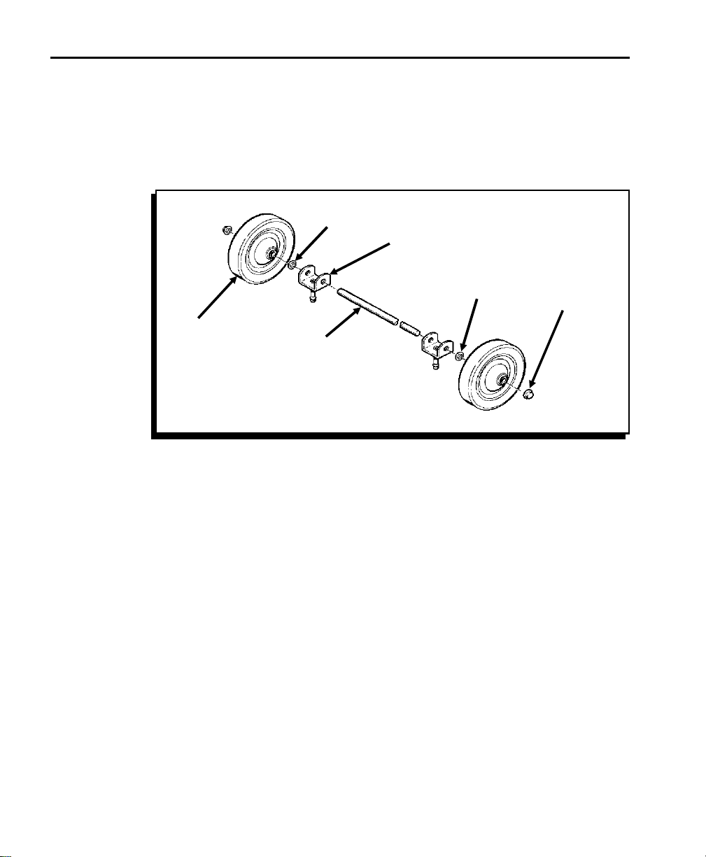
4. Slide the following parts, in this order, onto the axle: one
wheel, one washer, and two axle mounts. (Figure 1.)
Washer
Wheel
Axle
Axle
Mount
Figure 1
Washer
end
cap
nDo Not install the second end cap without first inserting the
axle mounts into the sockets. The sockets prevent the axles
from being positioned too close together.
1-4
Page 11
Chapter 1. Assembling the Station
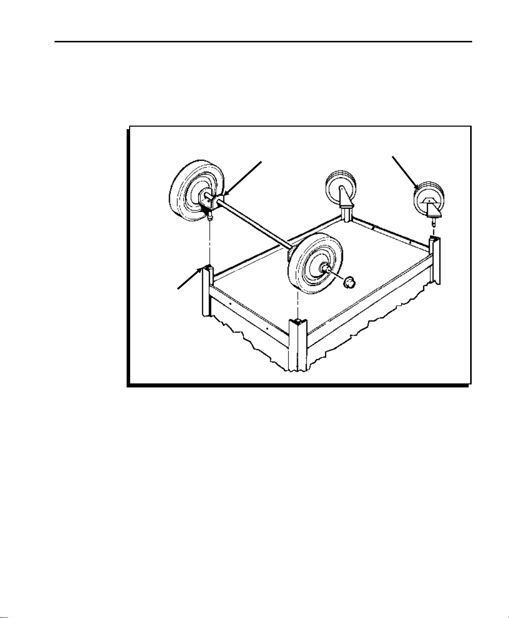
5. At the rear of the Station (end closest to the side where
the cabinet door opens), push the two axle mounts firmly
into the sockets of the rear legs. (Figure 2.) Hold onto
the uncapped end of the axle so the axle assembly stays
together.
Axle
Mount
Socket
Figure 2
Caster
6. Place the other end cap onto the uncapped end of the
axle. Press the cap firmly (with your thumb) to temporarily
hold the cap in place.
7. Hold the axle firmly with one hand, while tapping the end
cap onto the axle with a rubber mallet. Make sure the end
cap fits firmly onto the axle.
8. Push the two casters into the sockets in the bottom of the
front legs. (Figure 2.)
9. Tap the axle mounts and casters with a rubber mallet to
fully seat them.
1-5
Page 12
9476 Assembly and Setup Instructions
Step 2: Adjusting the Station’s Height--------------------------------------------------
1. Remove the following items from their packaging:
F (4) 1/4"-20 x 3/4" bolts (black)
F (4) 1/4"-20 wing nuts (black)
F (1) plastic cable-tube clamp (may already be attached
to the cable tube)
2. Turn the Station right side up.
3. Open the Station’s cabinet and remove the packaging from
around the bottom of the cable tube and from the cables.
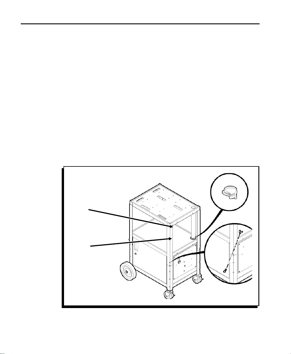
4. You might need another person’s help with this step. Lift
the top shelf to the second-highest height adjustment.
Make sure the cables inside the cable tube feed freely as
you lift the top shelf. Insert bolts into the holes in all four
legs and fasten them with wing nuts as shown. (Figure 3.)
1-6
Cable
Tube
Cable
Clamp
Figure 3
Page 13

Chapter 1. Assembling the Station
nDo Not set the top shelf to the highest adjustment.
5. Attach the plastic cable-tube clamp around the bottom of
the cable tube as shown (if it is not already attached).
Squeeze the finger grips to lock the clamp around the
cable tube. Use pliers to secure the cable clamp tightly.
(Figure 3.)
Step 3: Attaching the Cabinet Handle and Cord Bracket ------------------
Follow the steps below to install the cabinet handle and cord
bracket.
1. Remove the following items from their packaging:
F chrome handle insert
F two 5/8" phillips screws (black)
F cord bracket
F two 8-32 x 1/2" slotted screws (black)
F two 8-32 nuts/lockwashers (black)
1-7
Page 14
9476 Assembly and Setup Instructions
2. Open the Station’s cabinet. Press the chrome handle
insert into the cabinet door and fasten it with two 5/8"
phillips screws. (Figure 4.)
Cord
Bracket
Handle
Insert
Figure 4
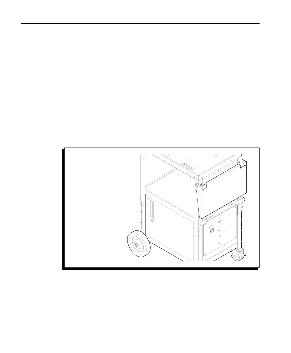
3. Position the cord bracket over the mounting holes on the
lower shelf’s edge shown. Fasten the bracket with two
1/2" slotted screws and 8-32 nuts/lockwashers. (Figure 4.)
Step 4: Attaching Optional Items----------------------------------------------------------
This section describes how to attach the optional drop shelf,
push handle, and data entry terminal cradle. Each optional
item and necessary mounting hardware is packaged
individually. These are optional items; if you did not order
them, skip to step 5.
1-8
Page 15
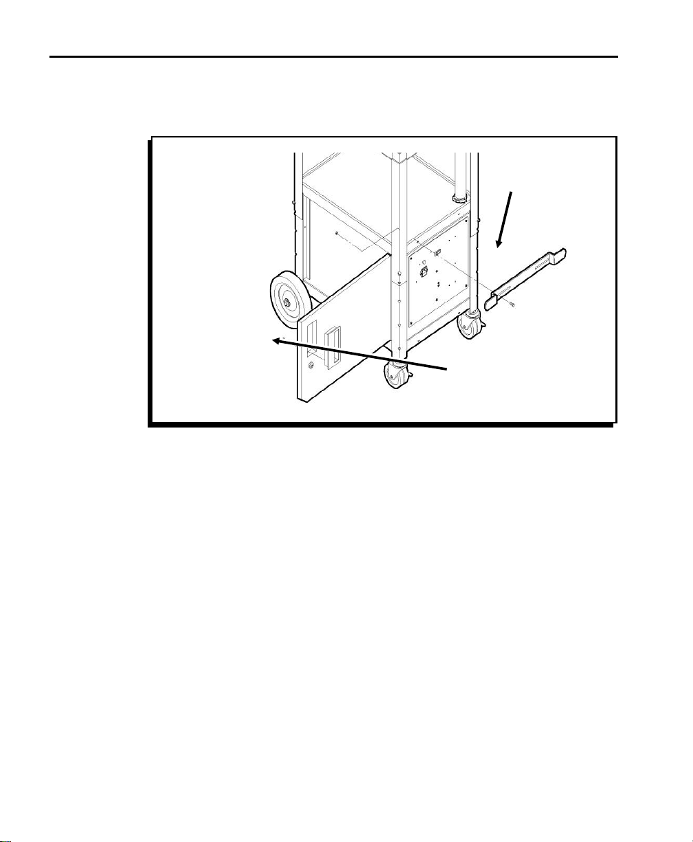
Attach the Push Handle
1. Remove the following items from their packaging:
F (1) push handle
F (4) 1/4"-20 x 3/4" hex bolts
F (4) 1/4"-20 nuts
F (4) 1/4"-20 washers
2. Attach the push handle to the front or rear of the Station
using four 3/4" hex bolts, 1/4"-20 washers, and 1/4"-20
nuts as shown. (Figure 5.)
Push
Handle
Chapter 1. Assembling the Station
Figure 5
1-9
Page 16
9476 Assembly and Setup Instructions
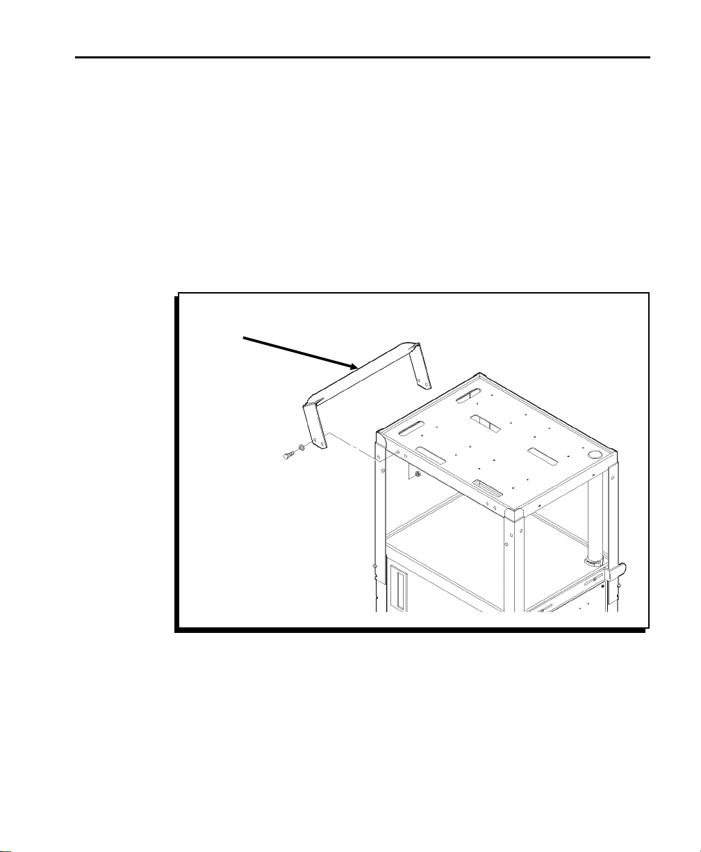
Attach the Drop Shelf
1. Remove the following items from their packaging:
F (1) support brace
F (1) metal rod
F (1) drop shelf
F (2) end caps
F (2) 1/4"-20 x 1/2" phillips screws
F (2) plastic washers
2. Attach the support brace to the Station’s corner supports
on either the front or the rear of the Station using two 1/2"
phillips screws. The open side of the support brace must
face down. (Figure 6.)
Support
Brace
Figure 6
nDo not tighten the screws completely.
1-10
Corner
Support
Page 17
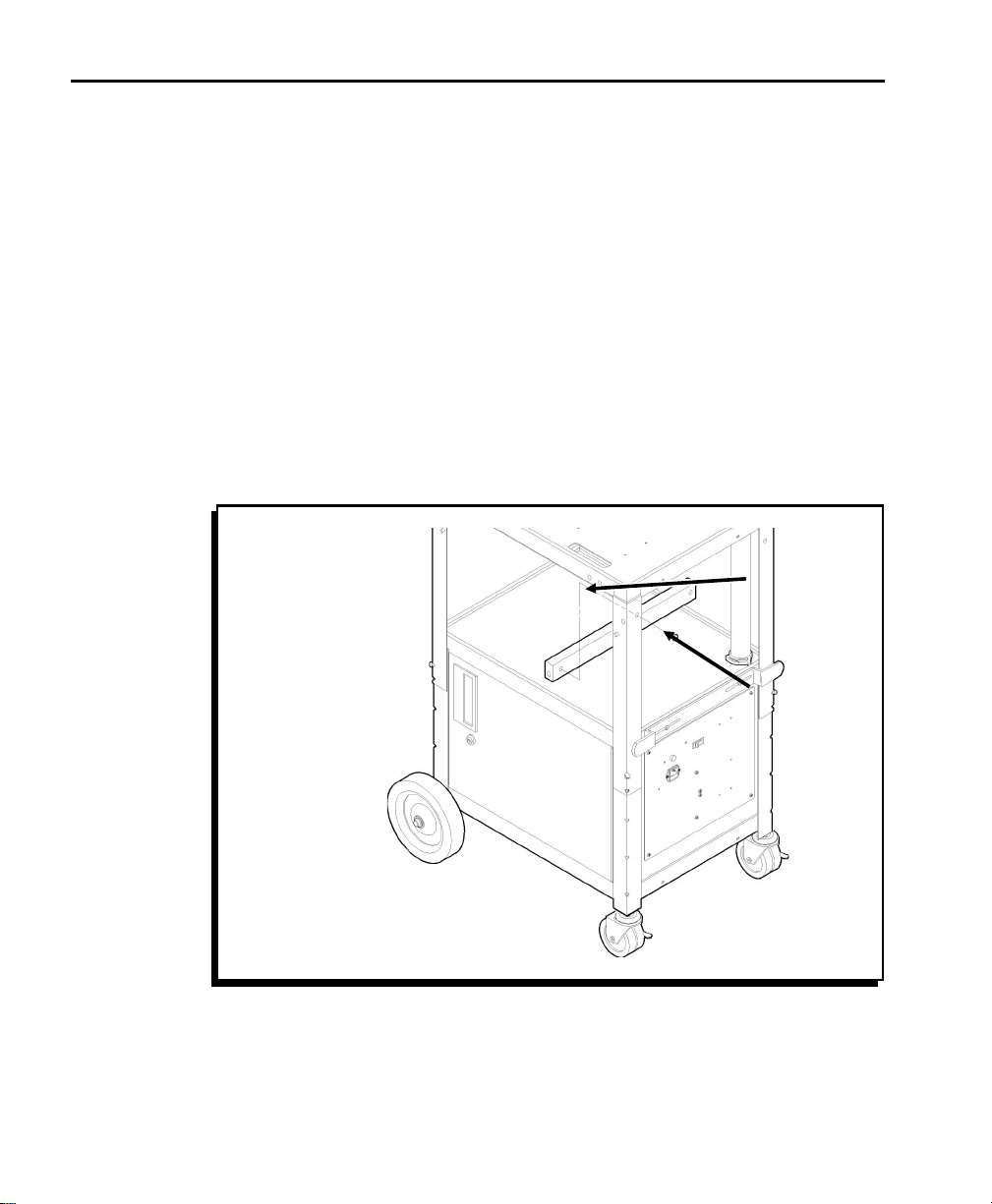
Chapter 1. Assembling the Station
3. Slide the metal rod into the hole in the Station’s corner
support and through the support brace until the rod exits
through the hole in the other corner support. You may
have to reach under the support brace to guide the rod
into the opposite hole.
4. Finish tightening the screws to secure the support brace.
5. Remove the metal rod.
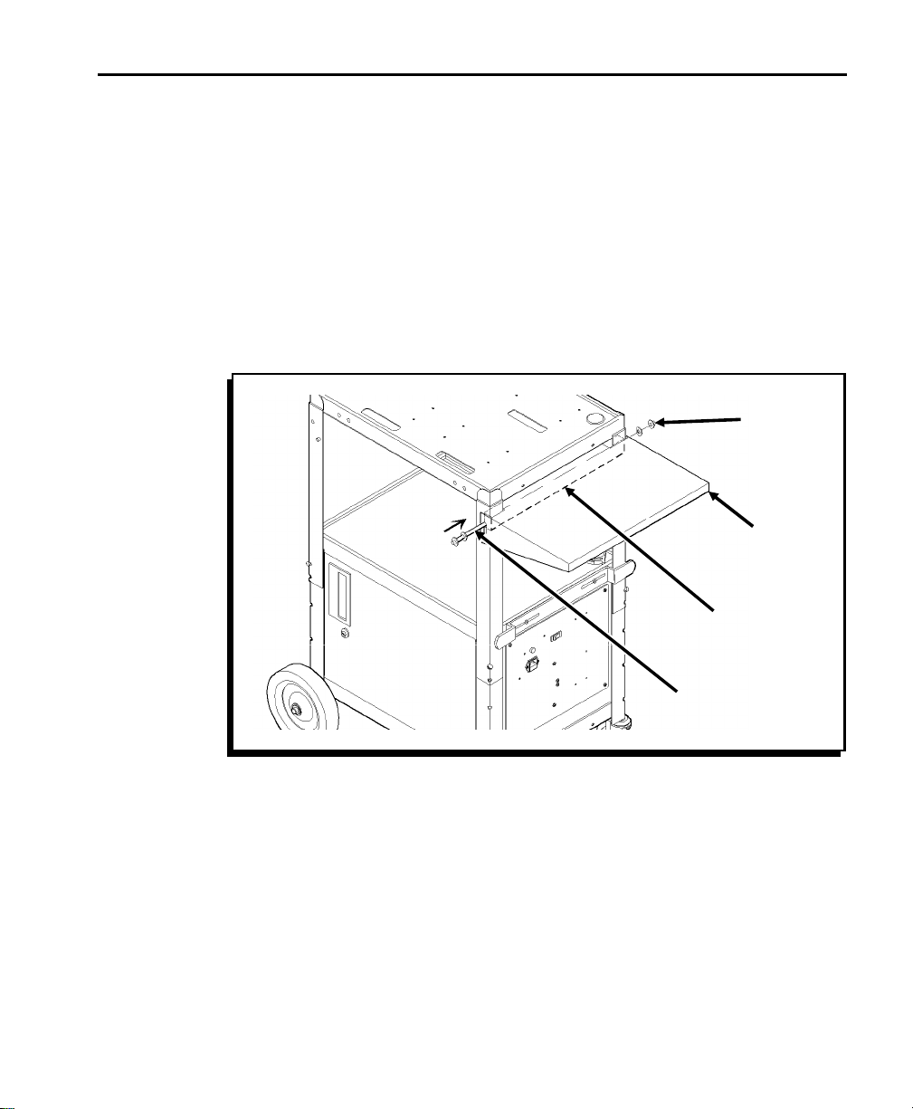
6. Position the rear lip of the drop shelf over the support
brace so the shelf rests in the extended position.
(Figure 7.)
end cap
Drop
Shelf
w
Support
Brace
Metal
Rod
Figure 7
To avoid hitting your fingers, use needle-nose pliers to hold
the end cap as you are hammering it.
7. On a firm surface, using a piece of cardboard for a pad,
stand the metal rod on one end. Hammer an end cap onto
the metal rod. The end cap should lock firmly.
8. Slide a plastic washer onto the metal rod.
1-11
Page 18
9476 Assembly and Setup Instructions
9. Slide the metal rod through the slot in the side of the drop
shelf and into the hole in the Station’s corner support.
Push the rod until it exits through the hole in the other
corner support. You may have to reach under the support
brace to guide the rod into the opposite hole. (Figure 7.)
10. Slide a plastic washer onto the exposed end of the metal
rod. (Figure 7.)
11. You might need another person’s help with this step. Hold
the head or side of a hammer firmly against the end of the
rod with the end cap. While maintaining pressure, use a
second hammer to hammer an end cap onto the exposed
end of the rod. The end cap should lock firmly. (Figure 7.)
12. To collapse the shelf, lift the shelf from the sides and allow
it to swing down. (Figure 8.)
1-12
Figure 8
To extend the shelf, lift the shelf until the rear lip slides
down onto the top of the support brace and locks in place.
Page 19
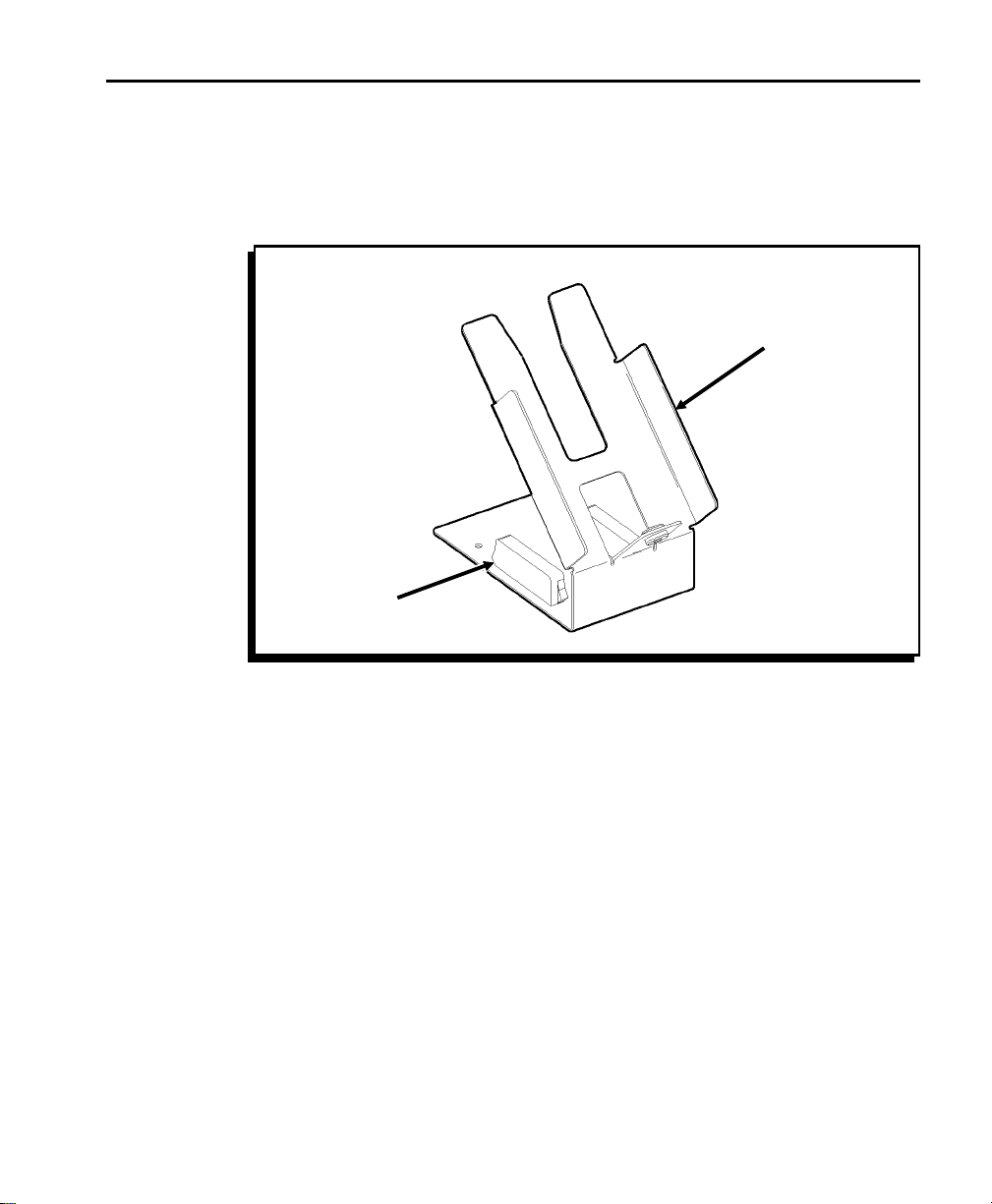
Attach the Data Entry Terminal Cradle
The data entry terminal cradle is shipped fully assembled. To
attach it, place it as shown on any of the Station’s shelves.
The magnets on the cradle anchor it to the Station. (Figure 9.)
Magnet
Chapter 1. Assembling the Station
Terminal
Cradle
Figure 9
1-13
Page 20

9476 Assembly and Setup Instructions
Step 5: Installing the Battery and Charger ------------------------------------------
Follow the steps below to install the battery and battery
charger.
Install the Battery
w
Only qualified service personnel may install or replace the
battery.
1. Remove the following items from their packaging:
F (1) 12-volt battery
F (2) metal retainer rods
F (2) 1/4"-20 wing nuts
F (1) rubber bracket
F (1) green wire
F (1) M5 x 10mm phillips screw
1-14
F (2) M5 x 15mm phillips/hex bolts
F (3) M5 nuts
F (2) 1/4"-20 washers
F (2) 1/4"-20 lockwashers
F (2) M5 washers
F (3) M5 lockwashers
Page 21

Chapter 1. Assembling the Station
2. Find the two holes in the floor toward the back of the
cabinet. Insert a retainer rod’s short end (end without the
threads) into one of the two holes as shown. Tilt the long
end of the retainer rod up until it slides down through the
hole. Repeat the process with the other retainer rod in the
other hole. (Figure 10.)
Retainer
Rod
Figure 10
1-15
Page 22

9476 Assembly and Setup Instructions
3. Place the battery on the cabinet floor. Remove the
cardboard packaging. Use a 15mm bolt, washer,
lockwasher, and M5 nut to attach the white battery wire to
the positive (+) battery post. (Figure 11.)
Green
Ground
Wire
Black
Wires
Negative (-)
Positive (+)
White
Wire
1-16
Figure 11
4. Slide the battery to the back of the cabinet.
5. Use a 15mm bolt, washer, lockwasher, and M5 nut to
attach the two black wires and green (ground) wire to the
negative (-) battery post. (Figure 11.)
6. Position the battery between the retainer rods. The writing
on the battery should face out. (Figure 12.)
Page 23

Chapter 1. Assembling the Station
7. Place the rubber bracket across the top of the battery.
Use 1/4"-20 wing nuts, washers, and lockwashers to
attach the retainer rods to the rubber bracket. Tighten
both wing nuts equally to secure the battery. (Figure 12.)
Rubber
Bracket
Retainer
Rod
Ground
Wire
Figure 12
1-17
Page 24

9476 Assembly and Setup Instructions
Install the Battery Charger
1. Remove the following items from their packaging:
F (1) battery charger
F (2) metal retainer rods
F (1) rubber bracket
F (2) 1/4"-20 wing nuts
F (2) 1/4"-20 washers
F (2) 1/4"-20 lockwashers
F (1) power cord (packaged with the battery charger)
F (1) power cord (heavy-duty)
1-18
Page 25

Chapter 1. Assembling the Station
2. Find the two holes in the floor toward the front of the
cabinet. Insert a retainer rod’s short end (end without the
threads) into one of the two holes as shown. Tilt the long
end of the retainer rod up until it slides down through the
hole. Repeat the process with the other retainer rod in the
other hole. (Figure 13.)
Retainer
Rod
Figure 13
1-19
Page 26

9476 Assembly and Setup Instructions
3. Insert the power cord (packaged with the battery charger)
into the power socket on the back of the charger. (Figure
14.)
Battery
Socket
Battery
Cable
Voltage
Selector
1-20
Power
Cord
Figure 14
Power
Socket
4. Insert the battery cable into the battery socket on the back
of the charger. (Figure 14.) The cable is keyed.
5. Make sure the voltage selector switch on the back of the
charger is set correctly (115V in U.S.).
6. Place the charger on the cabinet floor.
Page 27

Chapter 1. Assembling the Station
7. Position the charger between the retainer rods so the back
of the charger rests against the metal L-bracket. The
status lights on the front of the charger should face out.
(Figure 15.)
8. Place the rubber bracket across the top of the charger.
Use 1/4"-20 wing nuts, washers, and lockwashers to
attach the retainer rods to the rubber bracket as shown.
Tighten both wing nuts equally to secure the charger.
(Figure 15.)
Rubber
Bracket
Retainer
Rod
External Power
Socket
Figure 15
9. Plug the charger’s power cord into the power outlet on the
inside wall of the cabinet.
1-21
Page 28

9476 Assembly and Setup Instructions
10. Plug the heavy-duty power cord into the external power
socket on the outside panel of the Station. (Figure 15.)
nDo Not plug the external power cord into a wall outlet until you
are ready to charge the battery. See "Charging the Battery"
for important battery information.
11. Close and lock the cabinet.
Do Not store anything inside the cabinet other than the battery
and battery charger. The cabinet must remain locked at all
times and the key must be stored with qualified service
personnel.
Step 6: Installing the Printers ----------------------------------------------------------------
Follow the steps below to attach the printer brackets and
printers to the Station.
Attach the Printer Brackets
1. Remove the following items from their packaging:
1-22
F printer brackets (1-4, depending on your system)
F M4 x 8mm phillips sems screws and M4 nuts (4-16 of
each, depending on how many printers you have)
F (2) M3.5 x 10mm slotted shoulder screws per printer
F (2) M3.5 washers per printer
Page 29
Chapter 1. Assembling the Station
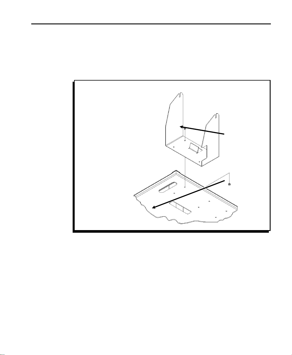
2. Position the printer bracket on the top shelf of the Station,
facing one of the Station’s fan-fold slots as shown. Align
the holes in the printer bracket with the holes in the shelf
and fasten with 8mm screws and M4 nuts. (Figure 16.)
nAll printer brackets must face the same direction.
Printer
Bracket
Fan-Fold
Slot
Figure 16
Attach the Printers
For each printer you install, follow these steps:
nSee your 9490 Operator’s Handbook for more information on
attaching the power pack and communication cable.
1-23
Page 30
9476 Assembly and Setup Instructions
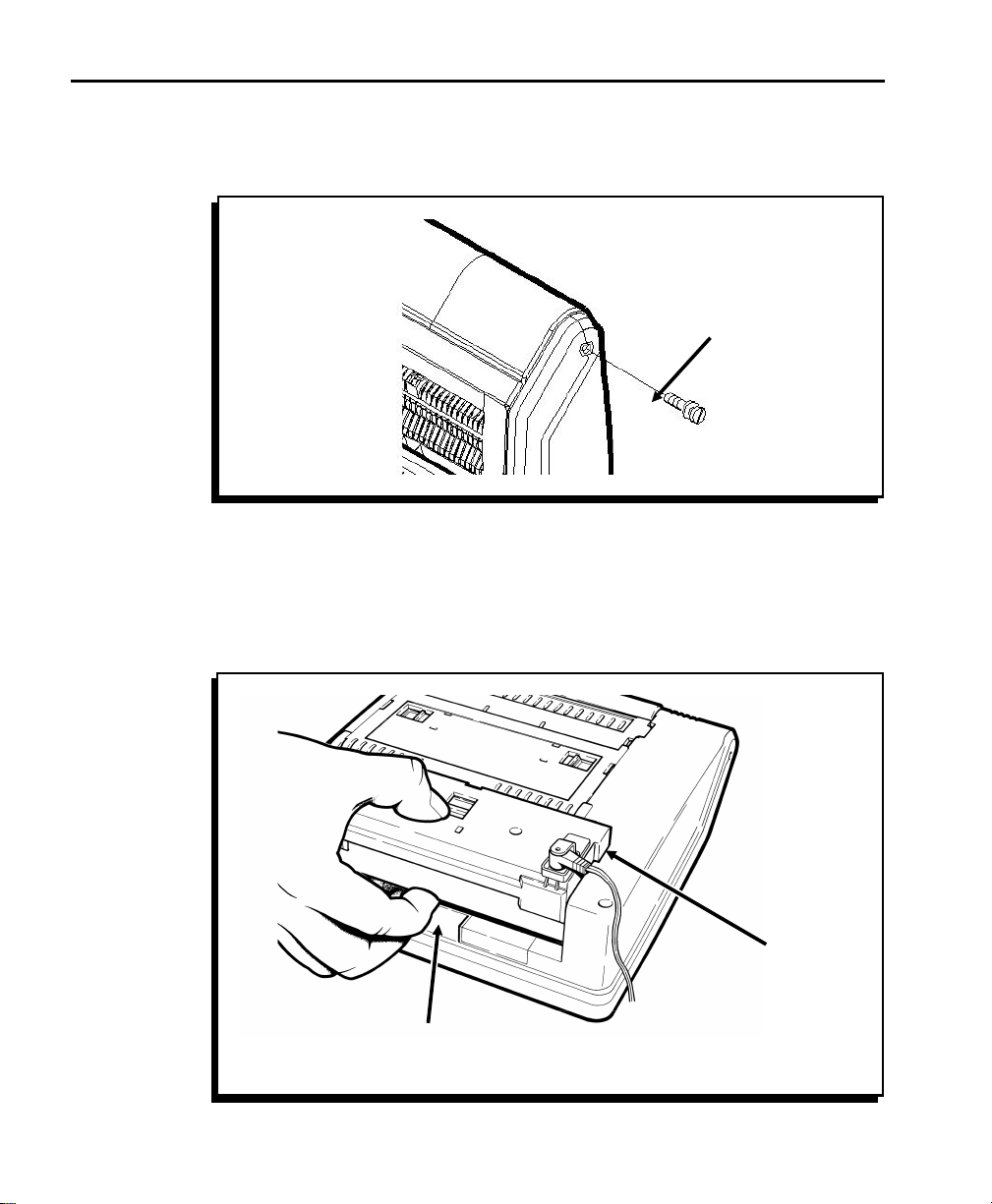
1. Insert two M3.5 washers and two 10mm shoulder screws
into the sides of the printer as shown and tighten with a
screwdriver. (Figure 17.)
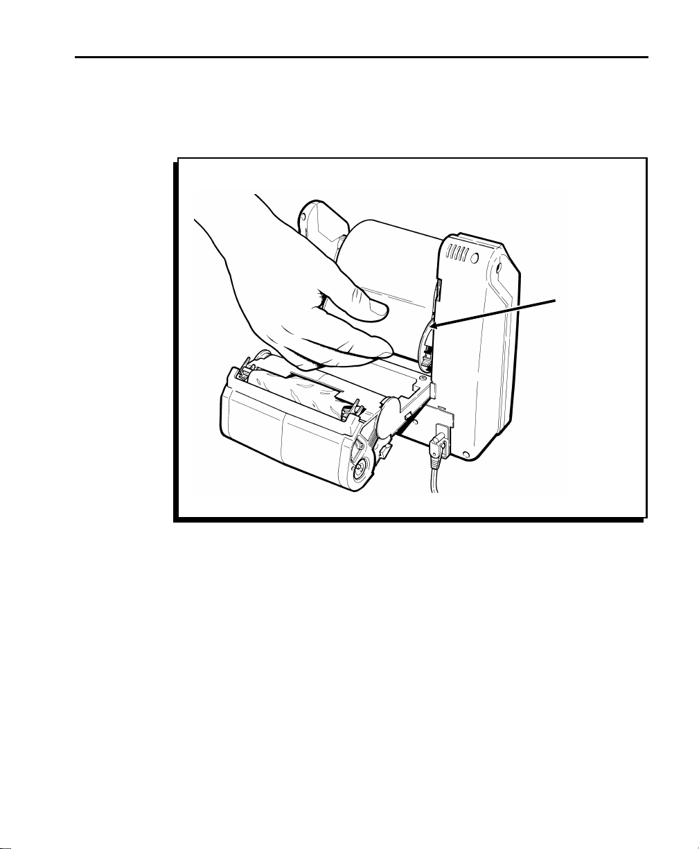
2. The power packs for the printers are attached to the
Station’s top shelf. Insert the tabs on the power pack into
the slots of the battery well in the base of the printer.
Push down until the latch snaps into place. (Figure 18.)
Shoulder
Screw
Figure 17
1-24
Power
Pack
Battery
Well
Figure 18
Page 31
Chapter 1. Assembling the Station
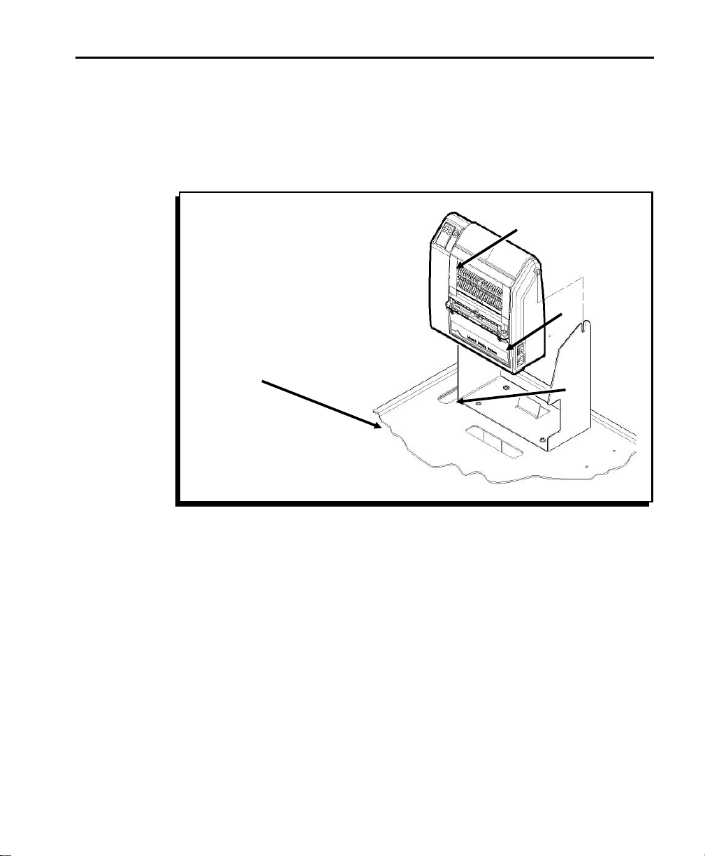
3. Slide the printer into the printer bracket so the printer
faces the fan-fold slot in the Station’s top shelf. The
printer’s shoulder screws slide into the vertical slots in the
printer brackets. Make sure the back of the printer rests
against the upturned metal ledge on the printer bracket.
The printer should lean back slightly. (Figure 19.)
Shoulder
Screw
Printer
Bracket
Fan-fold
Slot
Metal
Ledge
Figure 19
1-25
Page 32

9476 Assembly and Setup Instructions
4. The communication cables for the printers are located
inside the Station’s cable tube. Insert the communication
cable into the printer port as shown. (Figure 20.)
Printer
Port
Cable
Figure 20
1-26
Page 33

Chapter 2. Loading Supplies
The Station can accommodate fan-fold printers or roll-fed
printers. Fan-fold printers can also print roll supplies. This
section describes how to load both types of supplies. See
your 9490 Operator’s Handbook to load roll supplies in roll-fed
printers.
nThe Station can accommodate a maximum of two fan-fold
printers if the fan-fold supply stack is longer than six inches.
Before loading supplies, you must open the printer:
1. Insert your fingers into the depression beneath the
faceplate and pull up. (Figure 21.)
Supply
Guide
Figure 21
Faceplate
2-1
Page 34

9476 Assembly and Setup Instructions
2. Pull the supply guide forward and down as shown.
(Figure 22.)
Supply
Guide
Figure 22
2-2
3. Tip the printhead assembly up and over the platen roller
as shown. (Figure 23.)
Printhead
Assembly
Platen
Roller
Pinch
Rollers
Peel
Bar
Figure 23
Page 35

Chapter 2. Loading Supplies
4. Slide the latches on the back of the printer toward the
center. (Figure 24.)
5. Continue to push the printhead assembly toward the rear
of the printer until it opens completely.
Latches
Figure 24
Loading Fan-Fold Supplies ----------------------------------------------------------------------
To load fan-fold supplies into your printer, follow the steps
below.
nWhen using fan-fold labels, load for non-peel mode only.
Non-peel mode feeds the labels through the printer without
peeling them from the backing paper. The printer does not
print fan-fold labels in peel mode.
1. Open the printer.
2-3
Page 36

9476 Assembly and Setup Instructions
2. Center a strip of supply over the supply deflector. The
supply deflector’s rubber O-rings must be positioned
inside the edges of the supply. (Figure 25.) If you do not
need to adjust the position of the O-rings, skip to step 6.
3. Lift one end of the supply deflector to remove it from the
supply well. You may have to gently spread the supply
holders apart to release the supply deflector. (Figure 25.)
Supply
Deflector
O-Ring
2-4
Figure 25
4. Roll the O-rings out of their tracks and into the new
positions.
5. Replace the supply deflector in the supply well.
(Figure 25.)
Page 37

Chapter 2. Loading Supplies
6. Fan all four sides of the supply stack and straighten any
curved or bent corners. This will prevent supplies from
sticking together and causing feed jams.
7. Place the supply stack on the bottom shelf, directly
beneath one of the Station’s fan-fold slots. The supply’s
liner side should face up, so the arrow next to the black
mark points toward the printer. Place the magnetic supply
brackets at the opposite corners of the stack as shown.
(Figure 26.)
Supply
Strip
Fan-Fold
Slot
Magnetic Supply
Bracket
Figure 26
8. Lift the supply strip up through the Station’s fan-fold slot.
(Figure 26.)
2-5
Page 38

9476 Assembly and Setup Instructions
9. Feed the supply’s leading edge into the printer’s fan-fold
slot. The black mark on the supply must be facing up; if it
is not, flip the supply stack over. Make sure the arrow
printed on the back of the supply points toward the printer.
Center the supply in the printer by lining up the black mark
within the centering notch. (Figure 27.)
10. Adjust the supply guides to the edges of the supply and
turn the latches to lock the supply guides in place.
(Figure 27.)
Fan-Fold
Slot
Arrow
Centering
Notch
2-6
Black
Mark
Supply
Guide
Latch
Figure 27
Page 39

Chapter 2. Loading Supplies
11. Continue feeding the supply strip through the fan-fold slot
until the strip exits through the back of the printer, under
the supply deflector. The supply strip should feed around
the supply deflector and over the top of the printer as
shown. (Figure 28.)
Supply
Deflector
Figure 28
2-7
Page 40

9476 Assembly and Setup Instructions
12. Feed the supply strip through the upper opening in the
supply guide. (Figure 29.)
Supply
Guide
Upper
Opening
2-8
Figure 29
13. To close the printer, push the top assembly toward the
printer, close the supply guide, and latch the faceplate into
place.
Page 41

Chapter 2. Loading Supplies
Loading Roll Supplies in Fan-Fold Printers------------------------------------------
To load roll supplies into your fan-fold printer, follow the steps
below.
1. Open the printer.
2. Lift one end of the supply deflector to remove it from the
supply well. You may have to gently spread the supply
holders apart to release the supply deflector. (Figure 30.)
Supply
Deflector
Figure 30
2-9
Page 42

9476 Assembly and Setup Instructions
3. Squeeze the tabs and adjust both supply holders to the
width of your supply. (Figure 31.)
Supply
Holder
Arrow
Width of
Supply
Figure 31
nMake sure the arrow at the end of the each supply holder
points to the correct width. The supply holders lock at each
width setting.
2-10
Tabs
Page 43
Chapter 2. Loading Supplies
4. Insert the roll of supplies between the supply holders
inside the printer and press until the supply roll snaps into
place. The supply roll should unwind as shown.
(Figure 32.)
Supply
Holder
Figure 32
nMake sure the supplies turn freely in the supply well.
2-11
Page 44

9476 Assembly and Setup Instructions
5. For non-peel mode printing, feed the supply strip through
the upper opening in the supply guide. (Figure 33.)
Supply
Guide
Upper
Opening
2-12
Figure 33
Page 45

Chapter 2. Loading Supplies
6. On-demand printing only: For peel mode printing, feed the
supply strip through the lower opening in the supply guide.
(Figure 34.) When you print, labels peel automatically
through the top opening in the label guide and the backing
paper exits out the bottom opening.
Supply
Guide
Upper
Opening
Lower
Opening
Figure 34
7. To close the printer, push the top assembly toward the
printer, close the label guide, and latch the faceplate into
place.
2-13
Page 46

9476 Assembly and Setup Instructions
Loading Ribbon ----------------------------------------------------------------------------------------
Use ribbon when printing on thermal transfer supplies.
To load the ribbon cassette into the printer:
1. Open the printer and remove the ribbon cassette.
(Figure 35.)
2-14
Ribbon
Cassette
Figure 35
2. Slide a new ribbon cassette onto the printhead assembly
until it slips into place.
3. Close the printer.
Page 47

Chapter 2. Loading Supplies
Reloading a Ribbon Cassette ------------------------------------------------------------------
To reload your ribbon cassette, remove the ribbon cassette
from the printer and follow these steps:
1. Locate the end of the cassette with the two latches.
nLocate the International Symbols for opening and closing.
( ) indicates the cassette is locked (closed). ( ) indicates
the cassette is unlocked (open).
2. Rotate both latches until they snap into the unlocked
position.
3. Lift off the half of the cassette without the latches and set
it aside. (Figure 36.)
Ridged End of
Take-up Reel
Latch
Gear
Ribbon
Spool
Foam
Washer
Latch
Figure 36
2-15
Page 48

9476 Assembly and Setup Instructions
4. Remove the used ribbon and take-up reel and discard.
Open a package of new ribbon.
nDo Not wrinkle or crush the ribbon.
5. With the ridged end of the take-up reel facing down, place
the ribbon roll on the spool with the foam washer (on the
half of the cassette with the latches). Do not push the
ribbon roll down onto the spool yet.
6. Feed the ribbon around the guides and place the take-up
reel onto the shorter spool.
7. Twist the ribbon roll back and forth as you firmly push it
down until it is seated on the spool.
nF Do Not force the ribbon roll down onto the spool; you could
damage the foam washer.
F Make sure the preprinted side of the ribbon faces out.
F Make sure the latches are still in the unlocked position
( ) before fitting the two halves of the cassette together.
2-16
F If you are using a 2-inch or 3-inch-wide ribbon, push the
core of the ribbon roll to seat the ribbon roll onto the
cassette’s spool. Do not touch the ribbon because it may
wrinkle and twist.
8. Replace the other half of the cassette. The two halves
should fit together completely. Rotate the latches until
they click into the closed position ( ).
9. Check to make sure that the ribbon is loaded correctly; the
ribbon should be wound tightly inside the cassette. Turn
the gear counterclockwise with your fingers until the black
portion of the ribbon is exposed.
10. If the ribbon does not advance, or if it is hard to turn the
gear, repeat the loading procedure.
Page 49

Chapter 2. Loading Supplies
Printing--------------------------------------------------------------------------------------------------------
To print supplies from the printers on the Station, follow the
steps below. See Addressing a Monarch 9490 Printer for
instructions on setting up your data collection application to
send commands to specific printers on the Station.
1. Connect your data collection unit to the Station’s
communication cable. (Figure 37.) This communication
cable serves all printers on the Station.
Communication
Cable
Figure 37
2. Turn on the Station’s power supply and turn on the printers
from which you want to print supplies. (Figure 38.)
Power
Switch
Figure 38
2-17
Page 50

9476 Assembly and Setup Instructions
3. Turn each printer on and press each printer’s trigger to
calibrate the supply. You are now ready to collect data
and print.
nTo conserve the battery, make sure the Station’s power switch
is turned off when not in use.
2-18
Page 51

Chapter 3. Charging the Battery
The Station’s battery charger is a fully automatic,
maintenance-free charger. You must charge the battery before
using the printers on the Station.
Status
Light
Figure 39
To charge the battery, plug the Station’s AC power cord into a
grounded outlet. The status light on the front of the Station
indicates that the station is receiving power. (Figure 39.)
Charge the Station’s battery:
F before using the Station for the first time (charge it for
6 hours)
F when a printer’s LED indicates a "low battery" condition
(see "Battery Life" for indications of low battery
conditions)
F when the Station is not in use.
nWhen the Station is not in use, always leave the battery
charger plugged in and charging. The battery charger is
"intelligent;" it monitors the battery condition and does not
overcharge the battery.
3-1
Page 52

9476 Assembly and Setup Instructions
Important Charging Information ----------------------------------------------------------
w
DANGER! RISK OF ELECTRICAL AND FIRE HAZARD.
CERTAIN ACTIONS MAY RESULT IN DEATH, SERIOUS
INJURY, SHOCK, OR BURNS.
F Do Not disassemble the battery charger; take it to an
authorized repair center for repair or service.
F Do Not operate the Station while the battery charger is
charging.
F Do Not expose the battery charger to rain or snow.
Never charge a frozen battery.
F Plug only into a grounded outlet with three holes. Do
Not alter the AC power cord or plug provided. Do Not
operate the battery charger with a damaged cord or
plug.
F Do Not let the battery remain fully or partly discharged
for a long time; keep it charged.
F If using an extension cord, you must use #18 or
heavier for lengths up to 50 feet, or #16 or heavier for
lengths up to 100 feet. Use of improper extension cord
could cause fire and electric shock.
3-2
F Pull on the plug rather than the cord when
disconnecting the battery charger. Locate the cords
where they will not be stepped on, tripped over, or
otherwise subjected to damage or stress.
F The battery must be charged when the voltage is
10.5V or less. Print a test label to determine the
voltage. The charger will not charge if the voltage is
less than 3 volts. Call Technical Support for
information about charging a "deeply discharged"
battery.
Page 53

Chapter 3. Charging the Battery
Battery Life ------------------------------------------------------------------------------------------------
If you leave the battery charger plugged in and constantly
charging when the Station is not in use, the battery life is
maximized for the application. The charger will not
overcharge the battery. The printer indicates the battery
condition with the LED as follows:
F slowly flashing green: low battery (battery is down to
11.5V). The printers still operate until the battery is
drained to 10.5V or lower.
F fast-alternating green and amber: battery is lower than
5V. Printers do not operate.
F no LED: dead battery
nThe length of the battery’s life is directly effected by the
number of discharge cycles, depth of discharge, charging
voltage, and the surrounding temperature. A cycle is the time
from which a battery is fully charged until it is fully discharged.
3-3
Page 54

9476 Assembly and Setup Instructions
3-4
Page 55

Chapter 4. Troubleshooting
This chapter describes how to solve some common problems,
as well as how to change the two fuses on the Station.
Solving Problems --------------------------------------------------------------------------------------
If you have problems you cannot correct, call Technical
Support at the number listed on the back of this manual. See
the 9490 Operator’s Handbook for solutions to problems with
your printers. See the MPCLII Packet Reference Manual for
solutions to problems with online packets.
Problem Action
Printer indicates
a low battery,
even when the
battery is
charged.
None of the
Station printers
print.
The printer’s battery voltage selection is
incorrect. When connected to the Station, the
printer must be set to 12 volts.
Print a test label. The printer voltage is
indicated after the printer’s model number.
Make sure the Model: line says M9490:12v.
See Addressing a Monarch 9490 Printer to
set the printer voltage.
There are three possible problems:
F The Station’s battery is low.
F One of the printers is set to an incorrect
voltage.
F One of the printers has a full data buffer.
Turn the printers off to clear the buffers. If
the printers still do not print, see the previous
error description to check each printer’s
voltage selection. If the voltage selection is
correct (12V), charge the Station’s battery.
4-1
Page 56

9476 Assembly and Setup Instructions
Changing Fuses------------------------------------------------------------------------------------------
There are two fuses for the Station: one connected to the
battery (battery fuse), and one connected to the external
power socket (AC fuse).
The power switch on the front of the Station must be off while
changing fuses. (The status light near the power switch
should be OFF.)
Changing the Battery Fuse
w
Only qualified service personnel may change the battery fuse.
1. Turn the Station’s power supply off and unplug the power
cord. (Figure 40.)
Power
Switch
4-2
Status
Light
Figure 40
Page 57

Chapter 4. Troubleshooting
2. Open the Station’s cabinet. Press and turn the fuse cover
as shown until it pops out. (Figure 41.)
Fuse
Cover
Fuse
Fuse
Figure 41
Holder
3. Pull the fuse out of the
cover. (Figure 41.)
4. Insert a 15 A, 32V, slow
blow fuse (size 3AG)
into the fuse cover until
the fuse is fully seated.
(Figure 42.)
Figure 42
5. Push the fuse cover into the fuse holder and turn
clockwise until it locks in place.
4-3
Page 58

9476 Assembly and Setup Instructions
Changing the AC Fuse
1. Turn the Station’s power supply off and unplug the power
cord. (Figure 43.)
Power
Switch
Figure 43
4-4
2. Unplug the other end of the power cord from the Station.
3. Use a flathead screwdriver to carefully pry open the fuse
cover (located under the power socket on the front of the
Station). (Figure 44.)
Fuse
Fuse
Figure 44
Cover
Page 59

Chapter 4. Troubleshooting
4. Slide the fuse holder out and remove the fuse. (Figure 44.)
5. Insert a 250VAC, 6.3-amp, slow blow fuse into the fuse
holder until the fuse snaps into place. (Figure 44.)
6. Push the fuse holder until it snaps back into place.
(Figure 44.)
7. Plug the power cord back into the power socket on the
Station.
4-5
Page 60

9476 Assembly and Setup Instructions
4-6
Page 61

Chapter 5. Specifications
This chapter describes the Station’s physical characteristics.
See your 9490 Operator’s Handbook for printer specifications.
Utility Cart ------------------------------------------------------------------------------------------------
Height 42 inches (106.7 cm) (not including
printers)
Width 18 inches (45.7 cm)
Length 24 inches (61.0 cm)
Capacity 250 lbs
Weight 125 lbs (with battery, charger, and four
printers)
Operating Limits 40
°F to 110 °F (5 °C to 43 °C)
nIf you are using thermal transfer printers (printers with
ribbons), the maximum operating temperature is 95
Battery --------------------------------------------------------------------------------------------------------
F 12-volt, 38 amp-hours, deep cycle (to 10.5V)
F Sealed lead-acid, non-venting (safety venting only), no
transportation restrictions
F Shelf Life/Charge Retention:
1 month 97%
3 months 91%
6 months 85%
°F (35 °C).
5-1
Page 62

9476 Assembly and Setup Instructions
F Cycle Use:
100% depth of discharge approx. 250 cycles
50% depth of discharge approx. 550 cycles
30% depth of discharge approx. 1200 cycles
Cycle Life is approximate and many factors effect an
individual battery’s performance.
Charger ------------------------------------------------------------------------------------------------------
Input 115VAC +/- 10% (60Hz). IEC connection
Output
F Reverse polarity and short circuit-proof
F Temperature compensated
F Low voltage start (can charge a
discharged battery, but the battery
must be greater than 3V.)
F Smart charging for deep cycle 12-volt
lead-acid or gelled-type battery
F 10-amp peak charging current tapering
to float/monitor charge
5-2
Page 63

Page 64

For supplies, service, or assistance call:
TOLL FREE:
1-800-543-6650 (In the U.S.A.)
1-800-263-4650 (In Canada)
www.monarch.com
Published by the Technical Communications Department.
Printed in the U.S.A.
 Loading...