

Page 1
System
System
Administrator's
Administrator's
Guide
Guide
Monarch
9460™
Printer
®
TC9460SA Rev. AE 12/07 ©2006 Paxar Americas, Inc. a subsidiary of Avery Dennison Corp. All rights reserved.
Page 2

Each product and program carries a respective written warranty, the only warranty on
which the customer can rely. Paxar reserves the right to make changes in the product, the
programs, and their availability at any time and without notice. Although Paxar has made
every effort to provide complete and accurate information in this manual, Paxar shall not be
liable for any omissions or inaccuracies. Any update will be incorporated in a later edition
of this manual.
© 2006 Paxar Americas, Inc. a subsidiary of Avery Dennison Corp. All rights reserved. No
part of this publication may be reproduced, transmitted, stored in a retrieval system, or
translated into any language in any form by any means, without the prior written permission
of Paxar Americas, Inc.
This equipment has been tested and found to comply with the limits for a Class B digital
WARNING
device, pursuant to Part 15 of the FCC Rules. These limits are designed to provide
reasonable protection against harmful interference when the equipment is operated in a
commercial environment. This equipment generates, uses, and can radiate radio
frequency energy and, if not installed and used in accordance with the instruction manual,
may cause harmful interference to radio communications. Operation of this equipment in
a residential area is likely to cause harmful interference in which case the user will be
required to correct the interference at his own expense.
RF Operation is subject to the following two conditions: (1) this device may not cause
interference, and (2) this device must accept any interference including interference that
may cause undesired operation of the device.
CANADIAN D.O.C. WARNING
This digital apparatus does not exceed the Class B limits for radio noise emissions from
digital apparatus set out in the Radio Interference Regulations of the Canadian
Department of Communications.
Le présent appareil numérique n'émet pas de bruits radioélectriques dépassant les limites
applicables aux appareils numériques de la classe B prescrites dans le Réglement sur le
brouillage radioélectrique édicte par le ministère des Communications du Canada.
Trademarks
9433, 9462, 9465, Monarch®, MPCL, and Sierra Sport are trademarks of Paxar Americas, Inc.
The Bluetooth® trademarks are owned by Bluetooth SIG, Inc.
Paxar® is a trademark of Paxar Corporation.
Avery Dennison® is a trademark of Avery Dennison Corporation.
Adobe and Acrobat are registered trademarks of Adobe Systems Incorporated.
Avery Dennison Printer Systems Division
170 Monarch Lane
Miamisburg, Ohio 45342
Page 3

TABLE OF CONTENTS
INTRODUCTION ......................................................................... 1-1
Using This Manual.................................................................. 1-1
Audience ............................................................................... 1-1
Using the Menu Charts ........................................................... 1-2
Using the Display and Buttons................................................. 1-2
Selecting an Option ............................................................. 1-3
Exiting an Option................................................................. 1-3
Printing ................................................................................. 1-4
Selecting a Language ............................................................. 1-5
USING DIAGNOSTICS ................................................................ 2-1
Diagnostics............................................................................ 2-1
Printer ................................................................................ 2-3
Test Label........................................................................... 2-3
Sensors .............................................................................. 2-6
Printhead ............................................................................ 2-8
Battery................................................................................ 2-9
View Totals .........................................................................2-9
Display ............................................................................. 2-10
Keyboard .......................................................................... 2-11
Communications................................................................ 2-12
RAM ................................................................................. 2-13
Data Dump........................................................................ 2-14
About ............................................................................... 2-15
Online Diagnostics ............................................................... 2-15
Service Diagnostics.............................................................. 2-16
File System.......................................................................... 2-16
i
Page 4

SETTING UP THE PRINTER ........................................................ 3-1
Stock Energy ......................................................................... 3-3
Backlight ...............................................................................3-4
LCD Contrast ......................................................................... 3-5
Printer ................................................................................... 3-6
Adjusting the Print Contrast.................................................. 3-7
Adjusting the Supply Position ............................................... 3-8
Adjusting the Print Position .................................................. 3-9
Setting the Margin Adjust ................................................... 3-10
Setting the Demand Sensor................................................ 3-11
Setting the Stock Sensor.................................................... 3-14
Selecting the Die Cut Sensor.............................................. 3-15
Selecting the Black Mark Sensor ........................................ 3-16
Selecting the Non-Indexed Sensor ...................................... 3-18
Selecting the Aperture Sensor ............................................ 3-19
Serial Communications ......................................................... 3-21
Baud Rate......................................................................... 3-22
Parity ............................................................................... 3-22
Data Bits........................................................................... 3-23
Stop Bits........................................................................... 3-23
Flow Control...................................................................... 3-24
Power Management .............................................................. 3-25
Low Power (Sleep Mode).................................................... 3-25
Shut Down ........................................................................ 3-26
ii
Page 5

RF Network.......................................................................... 3-26
About Bluetooth® ................................................................. 3-27
Defaults............................................................................ 3-28
Changing the Communication Settings ................................ 3-28
Bluetooth Settings ................................................................ 3-28
Enabling the Security......................................................... 3-29
Changing the PIN .............................................................. 3-30
Local Name....................................................................... 3-31
Local Address ................................................................... 3-32
Printing Info ...................................................................... 3-32
iii
Page 6

iv
Page 7

INTRODUCTION
Use this System Administrator's Guide for the Monarch® Sierra
Sport2™ 9460™ printer. Review the printer information in the Operator's
Handbook available on our Web site (www.paxar.com) before you read
this manual.
Note: Information in this document supercedes information in previous
versions. Check our Web site for the latest documentation and
release information.
1
Using This Manual
Following is a summary of the contents of this manual.
Chapter Contents
1 Introduction Information you should know before using the printer.
Using
2
Diagnostics
Setting Up the
3
Printer
Using printer diagnostics to print test labels, check
sensors, view inches printed, etc.
Using the setup menu to adjust the supply and printer
settings.
Audience
The System Administrator's Guide is for the person who sets up the
printer and changes the configuration.
Introduction 1-1
Page 8
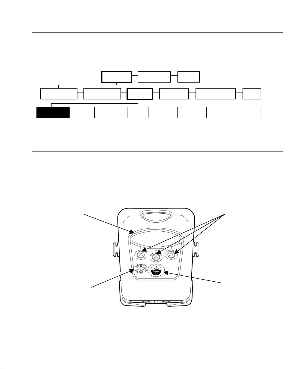
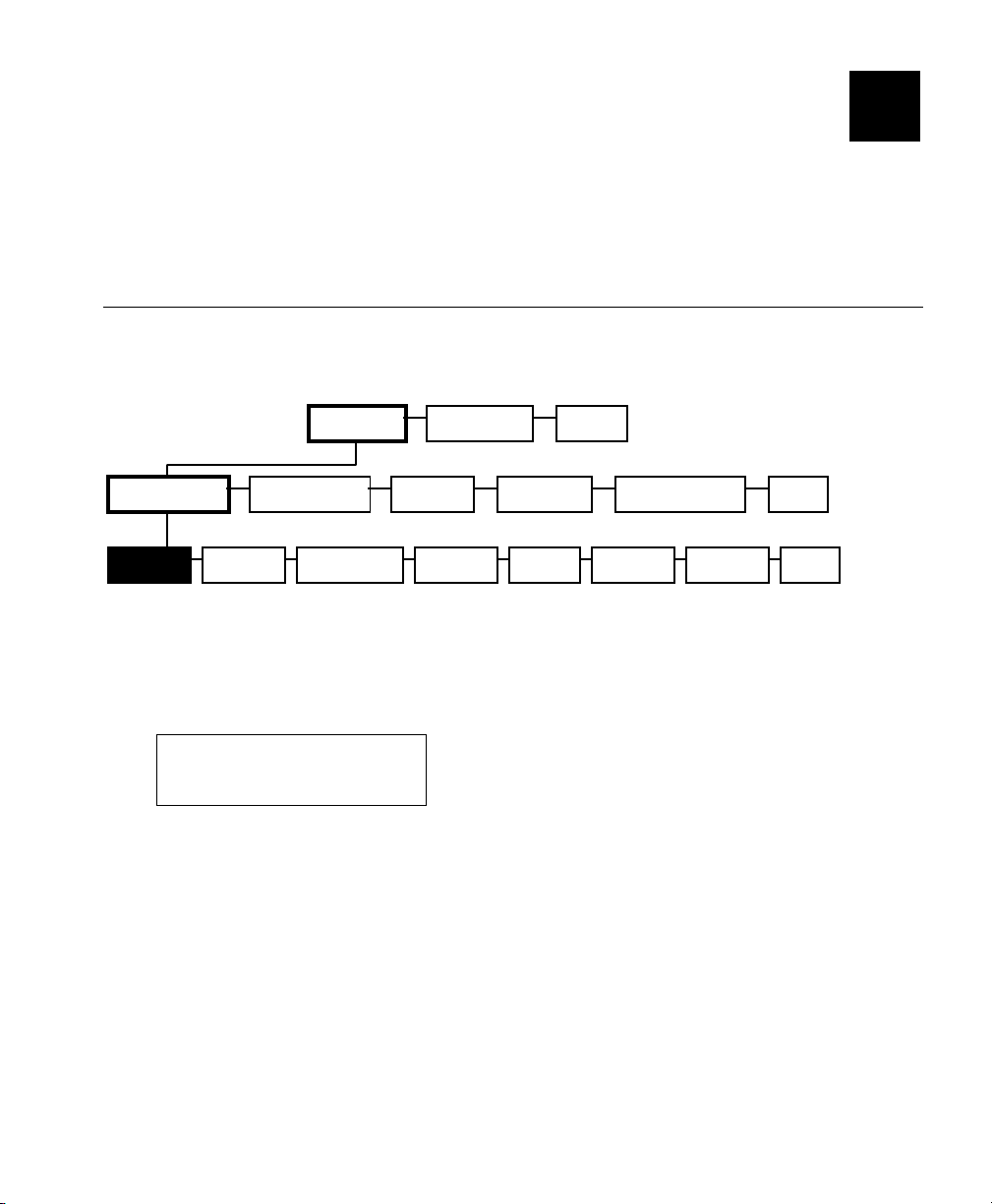
Using the Menu Charts
The chapters in this manual have one or more charts showing the
printer's menu structure. For example:
Main Menu
Tool Box
Diagnostics Online Diag.
Stock Energy Backlight LCD Contrast Printer Serial Comm. Power Mgmt. RF Network Bluetooth
Language Exit
Setup
Service File System Exit
Exit
The black boxes show where you are; the bordered boxes show how you
got there.
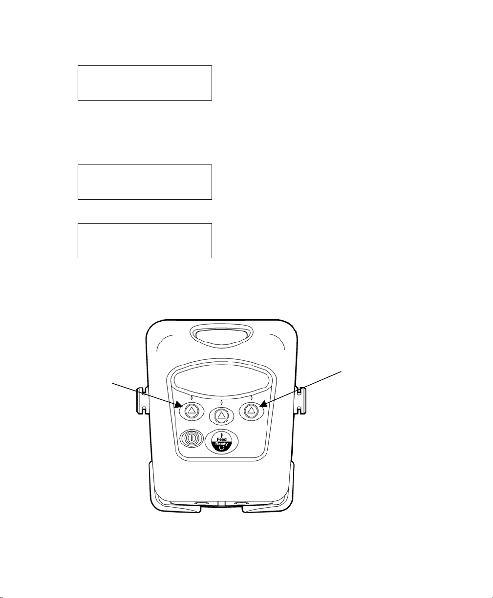
Using the Display and Buttons
P Turns the printer on and off.
F Advances the supply or returns the display to the next higher
menu.
A Three navigation buttons for selecting options on the display.
Display
Navigation
Buttons
Feed/Ready
On/Off Button
Button
1-2 System Administrator’s Guide
Page 9
The following table describes the icons you may see on the display:
When you see Press the NAVIGATION A button under the icon as
described
↵
c Scrolls up through the list of options.
d Scrolls down through the list of options.
f Sets the change position.
+ Toggles between positive and negative values.
Increases the selected setting in 1-step increments.
Increases the selected setting in 10-step increments.
- Decreases the selected setting in 5-step increments.
X
Returns the display to the next higher menu.
Selects (enters) the highlighted option.
Clears an error.
Selecting an Option
To display menu options, press any A.
♦ When the display shows a down arrow, press A under d to scroll
down through the list of options.
Diagnostics
Online Diag.
↵ d
♦ When the displays shows an up arrow, press A under c to scroll up
through the list of options.
Online Diag.
Setup
↵ c d
♦ When the option you want is highlighted, press A under ↵ (enter) to
select it.
Exiting an Option
To exit an option, press F once. You return to the next higher menu.
When you press F, you lose any entries you have made since the last
time you pressed A under ↵.
Introduction 1-3
Page 10

Printing
The host sends online packets containing print jobs to the printer.
1. Turn on the printer. Press and hold P until the display turns on.
The display flashes printer version information, battery charging
status, and then you see
Ready
װ
2. Download a format and a batch.
For information on creating packets and downloading print jobs,
refer to the Programmer's Manual available on our Web site
(www.paxar.com).
The printer prints either a strip of supplies (non-peel mode) or
one at a time (peel/on-demand mode).
3. Remove the printed supplies.
1-4 System Administrator’s Guide
Page 11
Selecting a Language
You can change the printer's messages to English, French, German,
Spanish, and Other (for future formats).
Main Menu
Tool Box
English Francais Deutsch Espanol Other Exit
Language
Exit
1. Turn on the printer. Press and hold P until the display turns on.
The display flashes printer version information, battery charging
status, and then you see
Ready
װ
2. Press A under װ.
E B F
f ² T
3. Press A under T (Tool Box) to enter the menu.
Tool Box
Language
↵ d
4. Press A under d until Language is highlighted.
5. Press A under ↵ to select Language.
English
Francais
↵ d
6. Press A under d to scroll through the options.
7. Press A under ↵ to select the highlighted option.
Introduction 1-5
Page 12

1-6 System Administrator’s Guide
Page 13
USING DIAGNOSTICS
A
2
This chapter explains how to use the Tool Box, Diagnostics menu.
Only System Administrators should perform these tests. You can view
test results but you cannot change any of the settings. If there is a
problem with the printer, give the results of these tests to Service.
Diagnostics
The Diagnostics menu helps diagnose problems with the printer.
Main Menu
Language Exit
Data
Dump
bout Exit
Diagnostics
Printer
Tool Box
Online Diag. Setup Service File System Exit
Display
Keyboard Comm. RAM
To exit, press F at any time.
1. Turn on the printer. Press and hold P until the display turns on.
The display flashes printer version information, battery charging
status, and then you see
Ready
װ
Using Diagnostics 2-1
Page 14
2. Press A under װ. You see the battery indicator E (empty) and
F (full):
E B F
f ² T
As you use the printer, the battery indicator line gets closer to E
(empty), instead of F (full). Recharge the battery when the line is
by the E.
3. Press A under T to enter the menu.
Tool Box
Language
↵ d
4. Tool Box is highlighted. Press A under ↵ to select Tool Box.
Enter Password
5. Press the navigational buttons in this order:
Left, Left, Left, Right, and Left.
Left
Navigation
Button
2-2 System Administrator’s Guide
Right
Navigation
Button
Page 15
Diagnostics
A
Online Diag.
↵ d
6. Diagnostics is highlighted. Press A under
↵ to select Diagnostics.
You are in the Diagnostics menu.
Printer
Use this menu to print a test label, check the sensors, printhead, battery,
and view totals.
Diagnostics Menu
Printer
Test Label Sensors Printhead Battery View Totals Exit
Display Keyboard Comm. RAM
Data
Dump
bout Exit
To exit, press F at any time.
Test Label
This option allows you to print three different types of test labels:
diagnostic labels, the test pattern, and the grey scale test label.
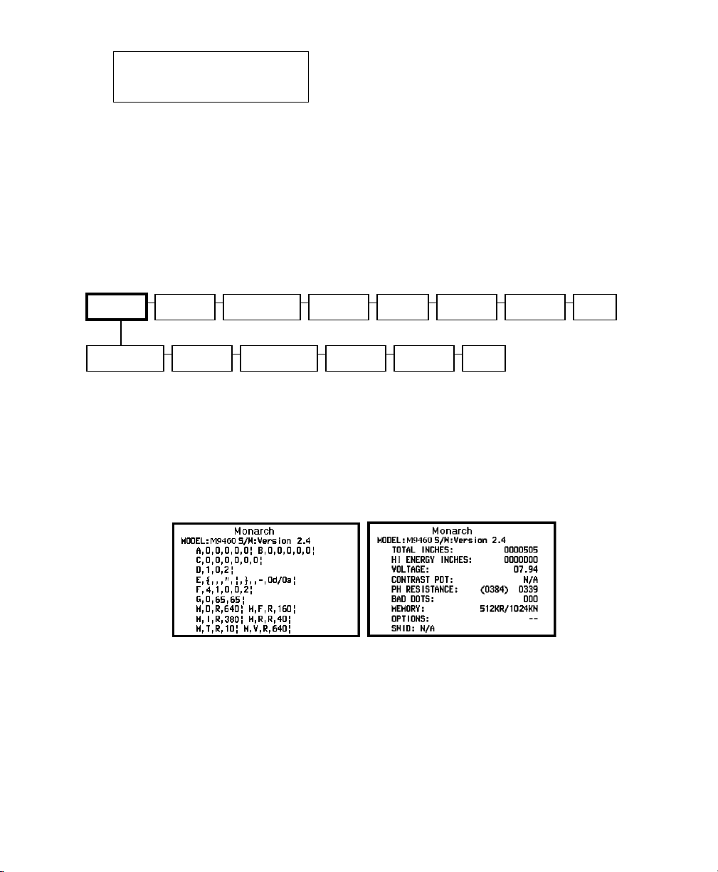
1. From the Diagnostics menu, select Printer, Test Label, Diag Label.
Two diagnostic labels print and you return to the Test Label
menu. The test labels show the printer's configuration, the model
number, and software version number.
Using Diagnostics 2-3
Page 16

The first label shows the printer's configuration by packet (A-M).
Refer to the Programmer's Manual for more information. The
second label shows the model number, software version, total
number of inches printed, number of high-energy inches printed,
voltage, contrast, printhead resistance, the number of bad dots,
memory, and any options.
You return to the Test Label menu.
2. Select Test Pattern.
A test pattern label prints and verifies the dots on the printhead
are working. You return to the Test Label menu.
If your printed sample has fewer lines or no lines, keep the
sample and call Service.
Note: You may receive a "Memory Full" error if you are using MPCL
because you need to reallocate memory. Refer to the
Programmer's Manual for more information.
2-4 System Administrator’s Guide
Page 17

3. Select Grey Scale.
A grey scale label prints to check the uniformity of the printing.
You return to the Test Label menu.
Label with voids
The test sample should be uniformly grey across the supply.
If you see voids, especially on the edges, save your sample and
call Service.
Note: You may receive a "Memory Full" error if you are using MPCL
because you need to reallocate memory. Refer to the
Programmer's Manual for more information.
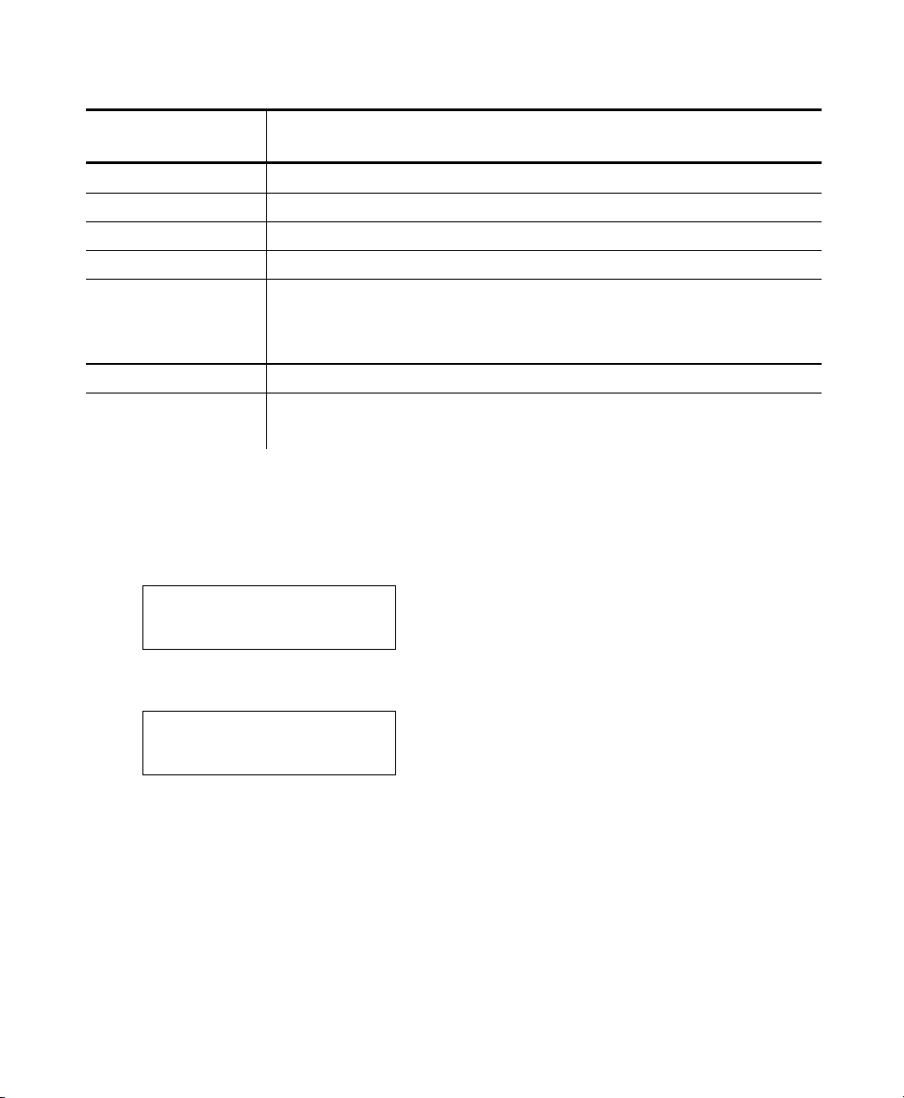
4. Select MIF Info.
MIF stands for Monarch Initialization
Files. MIF files specify parameters
for the printer.
A test label prints displaying the
settings for the printer. The line
beginning with SWID indicates if a
custom MIF file is loaded.
If there is no MIF file, you will see
“No MIF” and you will not get a test print.
You return to the Test Label menu.
5. Press F to return to the Diagnostics menu.
Using Diagnostics 2-5
Page 18

Sensors
Use this option to view the black mark, die cut, on-demand, and aperture
sensor settings.
To exit, press F at any time.
1. From the Diagnostics menu, select Printer, Sensors, Black Mark.
Black Mark
A/D Value = 170
↵
The acceptable range is between 0 and 255 and the A/D values
change as supply moves past the sensors. The count changes by
at least 100 steps when a black mark is under the sensor. If you
do not notice at least a 100-step difference, you may need to call
Service.
2. Press F to return to the Sensors menu.
3. Select Die Cut.
Die Cut
A/D Value = 170
↵
The acceptable range is between 0 and 255 and the A/D values
change as supply moves past the sensors. The count changes by
at least 100 steps when die cut labels move through the sensor.
If you do not notice at least a 100-step difference, you may need
to call Service.
4. Press F to return to the Sensors menu.
2-6 System Administrator’s Guide
Page 19

5. Select On-Demand.
On-Demand
A/D Value = 240
↵
The acceptable range is between 0 and 255 and the A/D values
change as supply moves past the sensors. The count changes by
100 steps when a label is not under the sensor. If you do not
notice a 100-step difference, you may need to call Service.
6. Press F to return to the Sensors menu.
7. Select Aperture.
Aperture
A/D Value = 225
↵
The acceptable range is between 0 and 255 and the A/D values
change as supply moves past the sensors. The count changes by
100 steps when a label is not under the sensor. If you do not
notice a 100-step difference, you may need to call Service.
8. Press F until you return to the Diagnostics menu.
Using Diagnostics 2-7
Page 20

Printhead
Use this option to check the printhead for bad dots, view the printhead
dot resistance and the printhead temperature.
To exit, press F at any time.
1. From the Diagnostics menu, select Printer, Printhead, Dot Test.
Print Head
Bad Dots = 0
↵
To print, the number of bad dots must be less than 10. If you
have more than 10 bad dots, call Service.
2. Press F to return to the Printhead menu.
3. Select Dot Resist.
Resistance
in Ohms = 170
↵
The acceptable range is between 247 Ohms and 458 Ohms. If
the resistance is not in this range, call Service.
4. Press F to return to the Printhead menu.
5. From the Printhead menu, select Temperature.
Temperature
Degree C = 25
↵
To print, the printhead temperature must be less than 60°C
(140°F). The temperature is displayed in Celsius.
6. Press A under ↵ or F to return to the Printhead menu.
7. Press F to return to the Printer menu.
2-8 System Administrator’s Guide
Page 21

Battery
Use this option to check the battery voltage.
1. From the Printer menu, select Battery.
Battery
Voltage = 7.74
↵
To print, the voltage must be greater than 7.0 volts.
2. Press A under ↵ or F to return to the Printer menu.
View Totals
Use this option to view the totals for printer inches, service inches,
printer high energy inches, and service high energy inches. The high
energy printing is used for linerless labels.
1. From the Printer menu, select View Totals, Print inch.
Printer Inches
00000060
↵
2. Press A under ↵ or F to return to the View Totals menu.
3. Select Service Inch.
Service Inches
00000060
↵
4. Press A under ↵ or F to return to the View Totals menu.
5. Select Prt High In.
Printer High
Inches
00000020
↵
6. Press A under ↵ or F to return to the View Totals menu.
Using Diagnostics 2-9
Page 22

7. Select Ser High In.
A
Service High
Inches
00000075
↵
8. Press A under ↵ or F to return to the View Totals menu.
9. Press F until you return to the Diagnostics menu.
Display
Use this menu to see if the backlight is working or if pixels are missing on
the display.
Main Menu
Diagnostics
Printer
Online Diag. Setup Service File System Exit
Display
Backlight Pixel Exit
Keyboard Comm. RAM
Data
Dump
bout Exit
To exit, press F at any time.
1. From the Diagnostics menu, select Display, Backlight.
Backlight Test
Press left key to
toggle backlight
2. Press the left A.
Backlight Test
Press left key to
toggle backlight
Backlight is ON
The left A is an ON and OFF toggle switch. Press the left A
again to turn ON or OFF the Backlight. You will see "Backlight is
ON" or "Backlight is OFF."
3. Press F to return to the Display menu.
2-10 System Administrator’s Guide
Page 23

4. Select Pixel.
A
Pixel Test
Press left key to
toggle pixel
display
Each dot on the display is called a pixel.
5. Press the left A. The display shows all pixels ON (black). If a pixel
is not on, make a note and call Service.
The left A is an ON and OFF toggle switch. Press the left A
again to turn OFF the pixels. The display shows all pixels OFF
(blank screen).
6. Press F until you return to the Diagnostics menu.
Keyboard
Use this menu to see if the buttons on the keyboard are working properly.
Main Menu
Diagnostics
Printer Display Keyboard Comm. RAM
Online Diag. Setup Service File System Exit
Data
Dump
bout Exit
To exit, press F at any time.
1. From the Diagnostics menu, select Keyboard.
Press key
2. Press each key one at a time except for P (power). The four boxes
on the display represent a key. If the keys are working correctly, the
boxes turn black.
Press feed to exit
If one of the boxes does not turn black, that key is not working
properly. Make a note and call Service.
3. Press the F button to return to the Diagnostics menu.
Using Diagnostics 2-11
Page 24

Communications
A
Use this menu to check the communications port and cable. You need a
loopback plug for this test. The loopback plug can be purchased at your
local electronics store. See Appendix A, "Specifications" for cable pinout information.
Main Menu
Diagnostics
Printer Display Keyboard Comm.
Online Diag. Setup Service File System Exit
RAM
Data
Dump
bout Exit
To exit, press F at any time.
1. From the Diagnostics menu, select Comm.
Insert loopback
Plug into serial
Port connector.
Press key to cont.
2. Press any A to continue.
The serial port test is performed.
Serial port test
Testing speed: ok
Testing parity: ok
Testing CTRLS: ok
Press key to cont.
3. Follow the instructions on the display. When you are finished, you
return to the Diagnostics menu.
2-12 System Administrator’s Guide
Page 25

RAM
A
Use this menu to check the printer's memory.
Main Menu
Diagnostics
Printer Display Keyboard Comm. RAM
Online Diag. Setup Service File System Exit
Data
Dump
bout Exit
To exit, press F at any time.
1. From the Diagnostics menu, select RAM.
RAM test running
RAM test passed
Press a key
2. If you see a RAM error message, call Service.
3. Press any key except P (power) to return to the Diagnostics menu.
Using Diagnostics 2-13
Page 26

Data Dump
A
Use this menu if you are having problems with a data stream. Data Dump
captures the data from the communications port and prints that
information to a label.
Main Menu
Diagnostics
Printer Display Keyboard Comm. RAM
Online Diag. Setup Service File System Exit
Data
Dump
bout Exit
To exit, press F at any time.
1. From the Diagnostics menu, select Data Dump.
Data Dump
A couple of labels print with data
from the communication port.
Data Dump
Press any key to
exit.
2. Press any key except P (power) to return to the Diagnostics menu.
2-14 System Administrator’s Guide
Page 27

About
A
Use this option to view information about the printer model and software
version.
Main Menu
Diagnostics
Printer Display Keyboard Comm. RAM
Online Diag. Setup Service File System Exit
Data
Dump
bout Exit
To exit, press F at any time.
1. From the Diagnostics menu, select About.
ABOUT M9460
Version 2.6
H/W Rev - P
2. Press F until you return to the Tool Box menu.
Online Diagnostics
Online Diagnostics is only for Service Representatives, because it
requires additional PC software. It allows Service to diagnose printer
problems.
Main Menu
Diagnostics
Online Diag.
Enable Disable Exit
Setup Service File System Exit
Using Diagnostics 2-15
Page 28

Service Diagnostics
Service Diagnostics is only accessible to a Paxar Representative,
because it requires a separate password. Before calling Service, print a
test label.
Main Menu
Tool Box
Diagnostics Online Diag. Setup
Language Exit
Service
Password
File System Exit
File System
The File System is only accessible to a Paxar Representative, because it
requires a separate password. It clears all files that are downloaded to
flash, but keeps all application files.
Main Menu
Tool Box
Diagnostics Online Diag. Setup Service
Language Exit
File System
Clear Files Clear MIF Pack Files Exit
Exit
2-16 System Administrator’s Guide
Page 29

SETTING UP THE PRINTER
This chapter explains how to use the Tool Box, Setup menu to
configure the printer.
Main Menu
3
Tool Box
Diagnostics Online Diag.
Stock Energy Backlight LCD Contrast Printer Serial Comm. RF Network Bluetooth Exit
Language Exit
Setup
Service File System Exit
Power Mgmt.
To exit, press F at any time.
1. Turn on the printer. Press and hold P until the display turns on.
The display flashes printer version information, battery charging
status, and then you see
Ready
װ
2. Press A under the װ icon. You see the battery indicator E (empty)
and F (full).
E B F
f ² T
Setting Up the Printer 3-1
Page 30

As you use the printer, the battery indicator line gets closer to E
(empty), instead of F (full). Recharge the battery when the line is
by the E.
3. Press A under T (Tool Box) to enter the menu.
Tool Box
Language
↵ d
4. Tool Box is highlighted. Press A under ↵ to select Tool Box.
Enter Password
5. Press the navigational buttons in this order:
Left, Left, Left, Right, and Left.
Diagnostics
Online Diag.
↵ d
6. Press A under d until Setup is highlighted.
7. Press A under ↵ to select Setup.
You are in the Setup menu.
3-2 System Administrator’s Guide
Page 31

Stock Energy
Use this menu to select the type of supplies you are using. The printer
supports standard or high energy supplies. Standard supplies can be
either tags or labels. Use the High Energy setting for linerless and
synthetic supplies. Use the Standard setting for standard supplies,
including tags and receipt paper.
Setup Menu
Diagnostics Online Diag.
Setup
Service File System Exit
Stock Energy
Standard
Backlight LCD Contrast Printer Serial Comm. RF Network Bluetooth Exit
Special
Exit High Energy
Power Mgmt.
Note: The "special" setting is reserved for future supply types.
Do not use this setting.
To exit, press F at any time.
1. From the Setup menu, select Stock Energy, Standard.
Standard
Supply
↵
2. Press A under ↵ to save the setting. You return to the Stock Energy
menu.
3. Select High Energy.
High Energy
Supply
↵
4. Press A under ↵ to save the setting. Use the High Energy setting for
linerless and synthetic supplies. Use the Standard setting for
standard supplies, including tags and receipt paper. You return to
the Stock Energy menu.
5. Press F to return to the Setup menu.
Setting Up the Printer 3-3
Page 32

Backlight
Use this menu to enable or disable the backlight. The display backlight
can be enabled for dimly lit areas. The default is disabled.
Setup Menu
Diagnostics Online Diag.
Stock Energy Backlight LCD Contrast Printer Serial Comm. RF Network Bluetooth Exit
Setup
Service File System Exit
Power Mgmt.
To exit, press F at any time.
1. From the Setup menu, select Backlight.
Disable
Enable
↵ d
2. Make your selection: Disable or Enable. For example:
Backlight
Enabled
X
The Backlight is turned ON.
3. Press A under X or press F to return to the Backlight menu.
4. Press F to return to the Setup menu.
3-4 System Administrator’s Guide
Page 33

LCD Contrast
Use this menu to adjust the LCD (display) contrast depending on your
viewing angle. The range is between 0 to 100. The default is 0.
Setup Menu
Diagnostics Online Diag.
Stock Energy Backlight
LCD Contrast
Setup
Printer Serial Comm. RF Network Bluetooth
Service File System Exit
Power Mgmt.
Exit
To exit, press F at any time.
1. From the Setup menu, select LCD Contrast.
Use keys to
Adjust Contrast
50
↵ - d
2. Press A under - to decrease the contrast or press A under + to
increase the contrast. The contrast changes in 5-step increments
(35, 40, 45, 50, etc.).
3. When the contrast you want is displayed, press A under ↵ to save
the setting.
You return to the Setup menu.
Setting Up the Printer 3-5
Page 34

Printer
Use this menu to change your printer's contrast, print positions, and
enable or disable the various sensors (on-demand, black mark, etc.).
Setup Menu
Diagnostics Online Diag.
Stock Energy Backlight LCD Contrast
Contrast Supply Pos Print Pos Demand Sensor Stock Sensor Exit
Printer
To exit, press F at any time.
Setup
Serial Comm.
Margin Adj
Service File System Exit
Power Mgmt.
RF Network
Bluetooth Exit
3-6 System Administrator’s Guide
Page 35

Adjusting the Print Contrast
Contrast controls the darkness of the printing on your supply. The range
is between -28 to 40. The default is 0.
You may need to adjust your contrast based on which supply you are
using. Linerless supplies may need a higher or lower contrast setting.
Receipt paper requires a lower contrast setting.
For linerless or synthetic supplies, you must select High Energy from the
Stock Energy menu.
1. From the Setup menu, select Printer, Contrast.
Print Contrast
+00
↵ f +
Use A as shown in the following table:
↵
Press A to
Enter
Save the setting
f
Press A to Press A to
Set the position (+00)
1st position
2nd position
3rd position
+
Toggle between
positive and negative
Increase the setting
by 10
Increase the setting by 1
2. When the setting you want is displayed, press A under ↵ to save the
setting.
You return to the Printer menu.
Setting Up the Printer 3-7
Page 36

Adjusting the Supply Position
Use this option to adjust how much supply feeds out of the printer. The
range is between -99 to 99. The default is 0. You may need to adjust the
supply in or out to allow
♦ tags and labels to be removed.
♦ die cut labels to be removed easily.
1. From the Printer menu, select Supply Pos.
Supply Position
+00
↵ f +
Use A as shown in the following table:
↵
Press A to
Enter
Save the setting
f
Press A to Press A to
Set the position (+00)
1st position
2nd position
3rd position
+
Toggle between
positive and negative
Increase the setting
by 10
Increase the setting by 1
2. When the setting you want is displayed, press A under ↵ to save the
setting.
You return to the Printer menu.
3-8 System Administrator’s Guide
Page 37

Adjusting the Print Position
Use this option to adjust where data prints vertically on the supply. The
range is between -99 to 99. The default is 0. Adjust the print if it is too
close to the top or bottom of the supply, or overtypes a pre-printed area.
1. From the Printer menu, select Print Pos.
Print Position
+00
↵ f +
Use A as shown in the following table:
↵
Press A to
Enter
Save the setting
f
Press A to Press A to
Set the position (+00)
1st position
2nd position
3rd position
2. When the setting you want is displayed, press A under ↵ to save the
setting.
+
Toggle between
positive and negative
Increase the setting
by 10
Increase the setting by 1
You return to the Printer menu.
Setting Up the Printer 3-9
Page 38

Setting the Margin Adjust
Use this option to adjust where the format prints horizontally on the
supply. The range is between -99 to 99. The default is 0.
1. From the Printer menu, select Margin Adj.
Margin Adjust
+00
↵ f +
Use A as shown in the following table:
↵
Press A to
Enter
Save the setting
f
Press A to Press A to
Set the position (+00)
1st position
2nd position
3rd position
2. When the setting you want is displayed, press A under ↵ to save the
setting. You return to the Printer menu.
+
Toggle between
positive and negative
Increase the setting
by 10
Increase the setting by 1
3-10 System Administrator’s Guide
Page 39

Setting the Demand Sensor
Use this option to enable or disable the on-demand sensor.
When you select:
♦ disable, printing is activated by pressing F.
♦ enable, printing is automatic when the previous printing is removed.
When using on-demand with the tear edge and peel mode, you need to
set up the printer:
♦ For tear edge, use only non-indexed supplies (continuous), supplies
without separations or black marks, and linerless supplies.
♦ For peel mode (separates the label from the liner).
To set the on-demand sensor:
1. From the Printer menu, select Demand Sensor.
Disable
Enable
↵ d
2. Make your selection: Disable or Enable. For example:
Sensor Enabled
↵
3. Press A under ↵ to save the setting.
Setup Supply...
Then hit Enter
↵
4. Setup your printer for the tear edge or peeling labels.
Setting Up the Printer 3-11
Page 40

For the tear edge:
1. Remove supplies or rewind the supplies enough to make sure there is
nothing under the sensor.
Tear edge
On-demand sensor
Note: The sensor needs to calibrate without supply under the sensor.
2. Close the supply door.
3. Press A under ↵ to continue.
SUCCESSFUL
↵ X
Note: If you see a "FAILED" message, call Service.
4. Press A under ↵ or press A under X to return to the Demand Sensor
menu.
5. Press F to return to the Printer menu.
6. Load supplies.
3-12 System Administrator’s Guide
Page 41

For peel mode:
1. Separate one or two labels from the liner and place the liner across
the exit chute.
Exit chute
2. Feed the liner under the peel bar. The sensor needs to calibrate the
liner only.
On-demand sensor
Peel bar
Liner
Setting Up the Printer 3-13
Page 42

3. Close the supply door.
For more information on how to load supply for peel mode, refer
to the Operator's Handbook.
4. Pull down on the liner to remove any slack.
5. Press A under ↵ to continue.
SUCCESSFUL
↵ X
Note: If you see a "FAILED" message, call Service.
6. Press A under ↵ or press A under X to return to the Demand Sensor
menu.
7. Press F to return to the Printer menu.
Setting the Stock Sensor
Use this option to set the sensor for die cut, black mark, non-indexed
(continuous), or aperture supplies. Select the correct sensor for the
supply type you are using.
Select the:
♦ Die-cut sensor for die cut supplies (labels on a liner with gaps
between the labels).
♦ Black mark sensor for black mark supplies (supplies with rectangular
marks on the back side of the liner or on the supply).
♦ Non-indexed sensor for non-indexed (continuous) supplies without a
black mark or perforations.
♦ Aperture sensor for supplies with holes (apertures) in them.
Note: If you have die cut supplies with black marks, select the black
mark sensor.
3-14 System Administrator’s Guide
Page 43

Selecting the Die Cut Sensor
1. From the Printer menu, select Stock Sensor, Die Cut.
Die Cut Sensor
Selected
↵
2. Press A under ↵ to continue.
Insert liner...
Then hit Enter
↵ ±
3. Load the supply by separating one or two labels from the liner and
placing the liner across the black mark sensor and through the exit
chute.
Exit chute
4. Close the supply door.
Setting Up the Printer 3-15
Page 44

5. Press A under ↵ to continue. You see a message that the printer is
calibrating the supply.
SUCCESSFUL
↵ X
The printer does not feed labels while calibrating. The printer
records the sensor value read from the liner.
Note: If you get a FAILED message: turn off the printer and repeat the
process. If it fails again, call Service.
6. Press A under ↵ or press A under X to return to the Stock Sensor
menu.
7. Press F to return to the Printer menu.
Selecting the Black Mark Sensor
1. From the Printer menu, select Stock Sensor, Black Mark.
Black Mark Sensor
Selected
↵
2. Press A under ↵.
Insert label...
Then hit Enter
↵ ±
3-16 System Administrator’s Guide
Page 45

3. Load the supply by placing the supply across the exit chute without a
black mark covering the sensor.
Black mark sensor
4. Close the supply door.
5. Press A under ↵ to continue. You see a message that the printer is
calibrating the supply.
SUCCESSFUL
↵ X
The printer does not feed supplies while calibrating. The printer
records the sensor value read from the label on the liner.
6. Press A under ↵ or press A under X to return to the Stock Sensor
menu.
7. Press the F button to return to the Printer menu.
Setting Up the Printer 3-17
Page 46

Selecting the Non-Indexed Sensor
1. From the Printer menu, select Stock Sensor, Non-Indexed.
Non-Indexed
Sensor Selected
↵
2. Press A under ↵.
Insert label...
Then hit Enter
↵ ±
3. Load the supply by placing the supply across the exit chute.
Exit chute
4. Close the supply door.
3-18 System Administrator’s Guide
Page 47

5. Press A under ↵ icon to continue. You see a message that the
printer is calibrating the supply.
SUCCESSFUL
↵ X
The printer does not feed supplies while calibrating. The printer
records the sensor value read from the label on the liner.
6. Press A under ↵ or press A under X to return to the Stock Sensor
menu.
7. Press F to return to the Printer menu.
Selecting the Aperture Sensor
1. From the Printer menu, select Stock Sensor, Aperture.
Aperture Sensor
Selected
↵
2. Press A under ↵.
Insert label...
Then hit Enter
↵ ±
3. Load the supply by placing the supply across the exit chute.
Exit chute
Setting Up the Printer 3-19
Page 48

4. Close the supply door.
5. Press A under ↵ to continue. You see a message that the printer is
calibrating the supply.
SUCCESSFUL
↵ X
The printer does not feed supplies while calibrating. The printer
records the sensor value read from the label on the liner.
6. Press A under ↵ or press A under X to return to the Stock Sensor
menu.
7. Press F until you return to the Setup menu.
3-20 System Administrator’s Guide
Page 49

Serial Communications
Use this menu to set the serial communication values. These values
provide the link for normal online printing.
Setup Menu
Diagnostics Online Diag.
Stock Energy Backlight LCD Contrast Printer RF Network
Baud Rate Parity Data Bits Flow Ctrl Exit
Setup
Serial Comm.
Service File System Exit
Power Mgmt.
Stop Bits
Bluetooth Exit
You need to set your serial communication values to match your
computer's online communications.
The serial communication values are shown below.
Option Choices Default
Baud Rate
1200/2400/4800/9600/
9600
19200/38400/57600/
115200
Parity None/Odd/Even None
Data Bits 7/8 8
Stop Bits 1/2 1
Flow Control
No Flow/DTR Flow/
DTR
RTS Flow/Xon/Xoff/Special
Setting Up the Printer 3-21
Page 50

Baud Rate
Use this option to set the printer's baud rate. Make sure the printer
settings match those at the host.
1. From the Setup menu, select Serial Comm, Baud Rate.
9600 BPS
19200 BPS
↵ c d
BPS = bits per second.
2. Make your selection: 1200, 2400, 4800, 9600, 19200, 38400, 57600,
or 115200 BPS. For example:
Baud = 9600
↵
3. Press A under ↵ to save the setting.
4. Press F to return to the Serial Comm. menu.
Parity
Use this option to set the printer's parity. Make sure the printer settings
match those at the host.
1. Select Parity.
No Parity
Odd Parity
↵ d
2. Make your selection: No Parity, Odd Parity, or Even Parity. For
example:
No Parity
↵
3. Press A under ↵ to save the setting.
4. Press F to return to the Serial Comm. menu.
3-22 System Administrator’s Guide
Page 51

Data Bits
Use this option to set the printer's data bits. Make sure the printer
settings match those at the host.
1. Select Data Bits.
8 Data Bits
Exit
↵ c d
2. Make your selection: 7 Data Bits or 8 Data Bits. For example:
8 Data Bits
↵
3. Press A under ↵ to save the setting.
4. Press F to return to the Serial Comm. menu.
Stop Bits
Use this option to set the printer's stop bits. Make sure the printer
settings match those at the host.
1. Select Stop Bits.
1 Stop Bit
2 Stop Bit
↵ d
2. Make your selection: 1 Stop Bit or 2 Stop Bits. For example:
1 Stop Bit
↵
3. Press A under ↵ to save the setting.
4. Press F to return to the Serial Comm. menu.
Setting Up the Printer 3-23
Page 52

Flow Control
Use this option to set the printer's flow control. Make sure the printer
settings match those at the host.
1. Select Flow Ctrl.
DTR Flow
RTS Flow
↵ c d
2. Make your selection: No Flow, DTR Flow, RTS Flow, XON/XOFF,
or Special. For example:
DTR Flow Ctrl
↵
3. Press A under ↵ to save the setting.
4. Press F until you return to the Setup menu.
If you change a setting, the new settings appear on the display.
For example:
New Selection
9600,N,8,1,No
Flow
Are you sure?
↵ X
5. Press A under ↵ to save the setting. Or, press A under X to exit
without saving the new setting.
3-24 System Administrator’s Guide
Page 53

Power Management
Use this menu to e set the amount of time before the printer goes into
sleep mode or automatically shuts down. When the printer is in sleep
mode, a coffee cup icon appears on the display.
Setup Menu
Diagnostics Online Diag.
Stock Energy Backlight LCD Contrast Printer Serial Comm. RF Network Bluetooth Exit
Setup
Service File System Exit
Power Mgmt.
Low Power (Sleep Mode)
When the printer is inactive for a selected period of time, it goes into low
power mode, or sleep mode, to conserve battery power. During sleep
mode, the printer is not operational.
The default is disabled (the printer does not go into sleep mode).
However, you can set the printer to go into sleep mode from 10 seconds
up to one (1) hour. The operator may press any button except the power
button (P) to wake up the printer.
Note: Do not send print jobs to the printer during sleep mode.
They will be lost.
1. From the Setup menu, select Power Mgmt, Low-Power.
Disable
10 Seconds
↵ d
Make your selection: Disable, 10 Seconds, 20 Seconds, 30
Seconds, 1 Minute, 2 Minutes, 5 minutes, 10 Minutes, 30
Minutes, or 1 Hour. For example:
Low Power
20 Seconds
↵
Setting Up the Printer 3-25
Page 54

2. Press A under ↵ to save the setting.
3. Press F until you return to the Setup menu.
Shut Down
You can set the printer to automatically shut down after a selected period
of time. Enabling the Shut Down option will turn off the printer
completely after the selected time period.
The default is disabled (the printer does not automatically shut down).
However, you can set the printer to go shut down from 10 minutes up to
30 minutes
1. From the Setup menu, select Power Mgmt, Shut Down.
Disable
10 Minutes
↵ d
Make your selection: Disable, 10 Minutes, 20 Minutes, or 30
Minutes. For example:
Shut Down
20 Minutes
↵
2. Press A under ↵ to save the setting. The printer will shut down after
20 minutes.
3. Press F until you return to the Setup menu.
RF Network
If you have a network printer, refer to the SNP System Administrator’s
Guide available on our Web site (www.paxar.com) for information about
configuring your RF settings using your network printer.
If your printer is not an RF printer and you try to access the RF Network
menu, "Not available" appears on the display.
3-26 System Administrator’s Guide
Page 55

About Bluetooth®
Bluetooth® wireless technology is a low-power consuming way to
communicate between devices. It has a maximum range of 30 feet (10m).
The Bluetooth device connects to your printer's serial port and conforms
to V2.0 of the Bluetooth specification.
Bluetooth device
Spacer
Make sure the +5V/DTR switch is set to the +5V position.
The printer defaults to receiving unencrypted data for the Bluetooth
device. However, to configure the Bluetooth device to change the PIN,
etc., you must use Version 2.6 or greater of the printer’s firmware.
Call Service if you want to upgrade your printer’s firmware.
Setting Up the Printer 3-27
Page 56

Defaults
The following defaults are set in the Bluetooth printer.
Function Default
Security none
PIN 0
Local Name MONARCH PRINTER
Changing the Communication Settings
To communicate with the Bluetooth device, make sure the communication
values are set to 9600, N, 8, 1, None. See "Serial Communications"
earlier in this chapter for more information.
Bluetooth Settings
Use this menu to enable or disable Bluetooth security, change the PIN,
modify the local name, view the local address, and print Bluetooth
information labels.
Setup Menu
To exit, press F at any time.
Diagnostics Online Diag.
Stock Energy Backlight LCD Contrast Printer Serial Comm. RF Network
Security Change Pin Local Name Address Exit
Setup
Service File System Exit
Power Mgmt.
Bluetooth
Print Info
If your printer is not a Bluetooth printer and you try to access the
Bluetooth menu, "Not available" appears on the display.
3-28 System Administrator’s Guide
Exit
Page 57

Enabling the Security
Use this option to enable or disable Bluetooth security.
1. From the Setup menu, select Bluetooth, Security.
Disable
Exit
↵ f d
2. Make your selection: Enable or Disable. For example:
Security Mode
Enabled
↵ f
3. Press A under ↵ to continue.
If security is enabled, you need to set a PIN. See "Changing the
PIN," for more information.
4. Press F until you return to the Bluetooth menu.
Setting Up the Printer 3-29
Page 58

Changing the PIN
Use this option to set the Bluetooth PIN. The PIN can be up to 15
characters: 0-9. Even though a space character is displayed while you
scroll through the values, the PIN cannot contain a space.
If security is enabled, you need to set a PIN. If security is disabled, you
do not need to set a PIN.
1. Select Change PIN.
The previous PIN value appears, for example:
PIN
123456
↵ f +
Use A as shown in the following table:
↵
Press A to Press A to Press A to
Enter
Save the setting
2. When you see the setting you need, press A under ↵ to save the
setting. "PIN Changed" appears briefly on the display and you return
to the Bluetooth menu.
f +
Scrolls through the
positions from left to
right
Scrolls through
numbers 0-9
If you need to clear digits from your PIN, make a space the
second digit, save the setting, and then select Change Pin again.
Only your first digit was saved, because the space is a
terminating character.
3-30 System Administrator’s Guide
Page 59

Local Name
Use this option to view and set the Bluetooth local name. The local name
can be up to 15 characters: upper-case letters A-Z, numbers 0-9, and the
space character.
The local name is used for identification purposes with the host, not
authentication. You should use a logical name for each printer, such as
warehouse, receiving dock, etc.
1. Select Local Name.
The default or last-saved local name appears, for example:
Local Name
WRHSE 1
↵ f +
Use A as shown in the following table:
↵
Press A to Press A to Press A to
Enter
Save the setting
2. When you see the setting you need, press A under ↵ to save the
setting. "Name Changed" appears briefly on the display and you
return to the Bluetooth menu.
f +
Scrolls through the
positions from left to
right
Scrolls through
numbers 0-9
Setting Up the Printer 3-31
Page 60

Local Address
Use this option to view the local Bluetooth address.
1. Select Address.
The local Bluetooth address is displayed, for example:
Local Address
00850123abc2
2. Press any A to return to the Bluetooth menu.
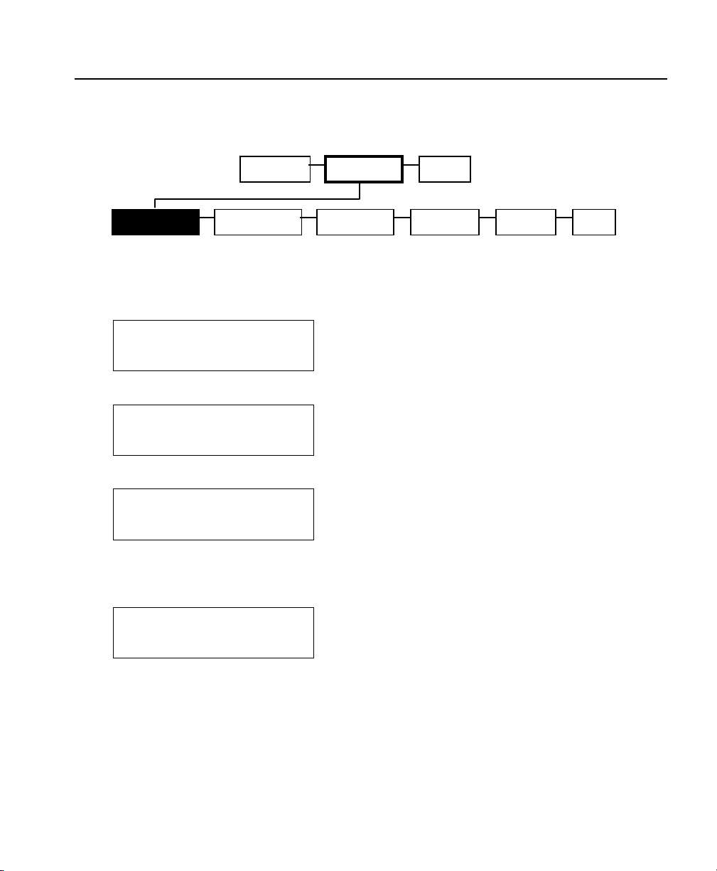
Printing Info
Use this option to print a Bluetooth information label. Use 2012 or 2015
supply or information may print off the label.
1. Select Print Info.
"Reading" appears briefly on the
display and then a Bluetooth
information label prints.
The Bluetooth Information label
prints the following information:
if Security is Enabled or Disabled,
the PIN, the Local Name, and the
Address of the Bluetooth device.
Security Disabled
PIN:
5
Name:
WRHSE 1
Address:
0850123abc2
Note: The Bluetooth information label also prints as a third test label
when you select Toolbox, Diagnostics, Printer, Test Label,
Diag Label.
2. You return to the Bluetooth menu. Press F to return to the Setup
menu.
3. Select Exit. "Please wait updating" appears briefly on the display.
3-32 System Administrator’s Guide
Page 61

Page 62

 Loading...