

Page 1

M
Equipment Manual
TC9445EM Rev. D 7/95
©1988 Monarch Marking Systems, Inc. All rights reserved.
Page 2

Each product and program carries a respective written
warranty, the only warranty on which the customer can rely.
Monarch reserves the right to make changes in the product
and the programs and their availability at any time and without
notice. Although Monarch has made every effort to provide
complete and accurate information in this manual, Monarch
shall not be liable for any omissi ons or inaccur ac ies. Any
update will be incorporated in a later edition of this manual.
WARNING
This equipment can interfere with radio communication if
not installed and used in accordance with the instruction
manual. It has been tested and found to comply with the
limits for a Class A computing device pursuant to FCC
Rules, Subpart B, Part 15, which provide reasonable
protection against such interference when operated in a
commercial environment. Operation in a residential area is
likely to cause interference which the user must correct at
their own expense.
CANADIAN D.O.C. WARNING
This digital apparatus does not exceed the Class A limits
for radio noise emissions from digital apparatus set out in
the Radio Interference Regulations of the Canadian
Department of Communications.
Le présent appareil numérique n’émet pas de bruits
radioélectriques dépassant les limites applicables aux
appareils numériques de la classe A prescrites dans le
Réglement sur le brouillage radioélectrique édicte par le
ministère des Communications du Canada.
Page 3

Preface
This manual contains information about the general setup and
maintenance of the 9445 printer. Some of the features in this
manual may not be available on your printer.
Other 9445 manuals include:
Preface
Operator’s
Handbook
User’s Manual
Programmer’s
Manual
Messages Manual
Explains how to enter data and print
labels.
Explains how to create and enter
formats. This manual also explains
special setup functions for the printer.
Explains communications and message
structures for sending formats and batch
data online.
Lists error messages and operator
responses.
i
Page 4

9445 Equipment Manual
ii
Page 5

Table of Contents
1. Installing the Printer
2. Loading Supply
Non-Peel Mode............ .......................... .............. .....2-1
Peel Mode.................................................................2-8
Loading Fan-Fold Supply .................... ....................2-16
Adjusting the Supply Sensor...................................2-18
Adjusting the On Demand Sensor.............. ............. 2-20
3. Loading a Ribbon
Loading a Ribbon Roll............... .. .. .... .. .. .. .... .. .. .. .... .. .. 3-2
Loading a Ribbon Cassette............. .. .... .. .. .... .. .. .. .... .. 3-6
4. Adjusting the Display
5. Cleaning the Printhead and Platen Roller
Appendix A. Converting the Keyboard for
T able Top Use
......................................................................A-1
.......................................................1-1
...............................................................2-1
............................................................ 3-1
....................................................4-1
Table of Contents
....................5-1
Appendix B. Troubleshooting
"Head Test Failure" Message....................................B-1
Start -Up and Pr inting................................................B-2
Start-Up and Printing (continued) .............................B-3
Cutting.......................................................................B-4
............................................B-1
iii
Page 6

9445 Equipment Manual
Appendix C. Specifications
Printer.......................................................................C-1
Supplies....................................................................C-2
...............................................C-1
iv
Page 7
1. Installing the Printer
1.
Place the printer on a level surface.
2.
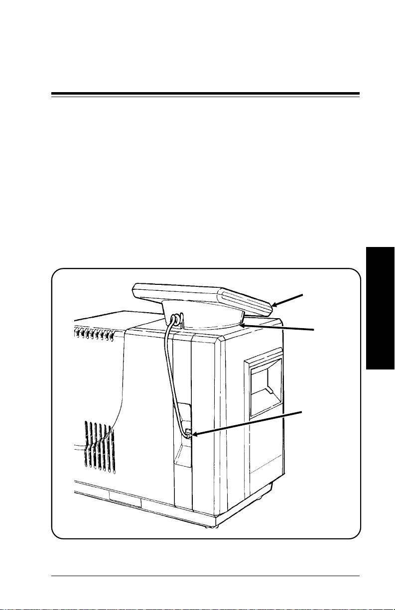
To install the keyboard on top of the printer:
a.
Remove the cord from the base of the keyboard.
b.
Plug the cord from the keyboard into the socket.
c.
Insert all of the cord ex ce pt a few co i l s back into the
base. Secure the cord by sliding a coil into the slot in
the base.
d.
Place the keyboard in the recess on top of the printer
as shown.
Installing the Printer
Keyboard
Recess
Socket
1-1
Page 8
9445 Equipment Manual
CAUTION
If your 9445 printer has been in storage below room
temperature, allow 10-12 hours for the printer to adjust to
room temperature
before
turning the power on. Failure to
do this may damage the printer.
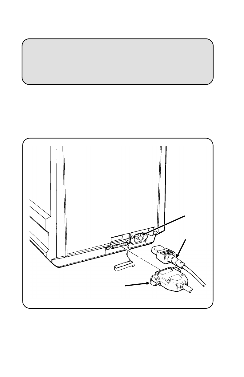
3.
Turn the power switch off and insert the power cord into
the socket. Plug the other end of the cord into a
grounded
115 VAC electrical outlet.
NOTE:
If you are going to use the printer online, also
connect the RS-232 cable.
Socket
Power Cord
RS-232 Cable
4.
On the initial startup, leave the printer on for 24 hours to
charge the new backup batteries.
1-2
Page 9

2. Loading Supply
The printer prints both tags and labels. The supply may be
wound with the printable side on either the inside or the
outside.
This chapter explains how to load supply for
•
Non-Peel Mode Printing (labels are printed in one strip.
This can be used with Continuous Printing.)
•
Peel Mode Printing (one label at a time while the
backing paper rewinds inside the printer. This must be
used with On Demand Printing.)
•
Fan-Fold Mode Printing (fan-fold supply is printed in
one strip). Call Service if you would like to use fan-fold
supply.
NOTE:
If your printer has a knife, follow the instructions under
"Non-Peel Mode ." You c annot use On Demand
printing with a knife. Also, if your printer has a knife, it
does not have the take-up spool shown in the
instructions for loading supply.
If you are going to use thermal direct supply (no
ribbon) and your printer is equipped with a ribbon roll
adapter, turn the thermal supply indicator to the right.
(See "Loading a Ribbon Roll" in Chapter 3.)
Non-Peel Mode
This mode is for both tags and labels. The printer dispenses
the desired amount of supply without separating the backing
paper from the label. This mode is us ually us ed with
continuous printing.
1.
Open the front panel.
Loading Supplies
2-1
Page 10
9445 Equipment Manual
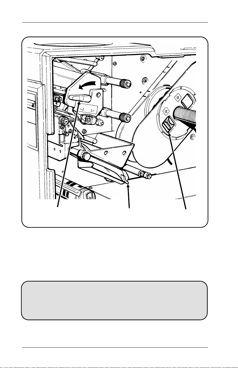
Printhead
Lever
2.
Turn the printhead lev er to the left to release the printhead.
3.
Hold down the lower supply guide and rewind the old
Lower Supply
Guide
supply roll, if there is one.
4.
Release the lower supply guide.
CAUTION
If you run out of supply while printing, pull the supply strip
back through the printer.
DO NOT
pull it forward through
the printhead. Pulling it forward may cause jamming.
2-2
Lock
Page 11
2. Loading Suppl y
5.
Push the lock to the right to unlock the outer supply holder
and remove the outer supply holder from the supply shaft.
Remove the old supply core, if there is one.
Supply
Core
Supply
Shaft
Outer Supply
Holder
2-3
Loading Supplies
Page 12

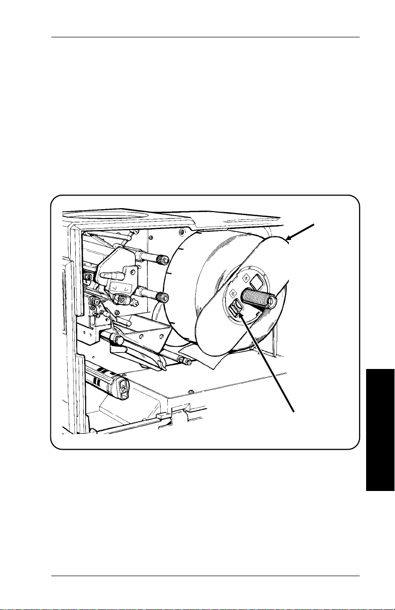
9445 Equipment Manual
6.
Place the new supply roll on the supply shaft as shown.
NOTE:
a.
b.
If your supply has a 3-inch (76.2 mm) core:
Remove the hub from the inner supply holder .
Reverse the outer supply holder (so the smooth side
faces the supply).
Supply
Shaft
Printable
Side Inside
7.
Fit the supply core onto the inner supply holder and hold it
in place.
2-4
Inner
Supply
Holder
Page 13
2. Loading Suppl y
8.
Turn the outer supply holder so the lock faces out. Align
the supply holder tabs with the tracks on the shaft.
9.
Push the supply holder onto the supply shaft, against the
supply.
10.
Push the lock to the left to secure the outer supply holder.
Make sure the supply is free to unwind.
NOTE:
When the outer supply holder is reversed (for
3-inch core supply), push the lock to the right to
secure the outer supply holder.
Supply
Holder
Loading Supplies
Lock
2-5
Page 14
9445 Equipment Manual
11.
Pull enough supply from the roll to reach the printhead.
12.
Hold down the lower supply guide.
13.
Feed the supply past the out-of-stock switch, between the
upper and lower supply guides, and up past the printhead.
Upper Supply
Printhead
Lower Supply
Guide
14.
Align the supply with the top edge of the upper guide and
Guide
Out-of-Stock
Switch
Outer Supply
Holder
Supply
slide it against the back wall (away from you). Continue
threading the supply up to the printhead as shown.
sure the ribbon does not snag or wrinkle
.
Make
2-6
Page 15
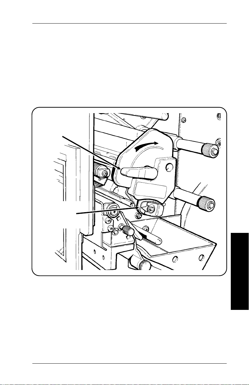
2. Loading Suppl y
15.
To adjust for wide or narrow supply, turn the supply width
adjustment knob to:
NARROW
•
WIDE
•
NOTE:
Printhead
Lever
Supply Width
Adjustment
Knob
for supply
for supply
two inches in width or smaller
greater than two inches in width.
Be sure the adjustment knob snaps back into
place after you turn it.
.
Loading Supplies
16.
Turn the printhead lev er to the right to lock the printhead.
2-7
Page 16

9445 Equipment Manual
17.
Turn the printer on. If you are:
•
replacing the supply with a new roll of the same size,
press f to align the printer.
•
changing supply size, adjust the supply sensor. See
"Adjusting the Supply Sensor" later in this chapter.
NOTE:
Before you print, be sure the menu supply type
setting matches your supply type (e.g. Black
Mark/Die Cu t). See your Operator’s Handbook to
set supply options.
Peel Mode
This mode is only used with labels. The printer separates the
label from the backing paper . This mode must be used with On
Demand printing.
1.
Open the front panel.
2.
Turn the printhead lev er to the left to release the printhead.
Printhead
Lever
2-8
Page 17

3.
If you are reloading supply:
a.
Cut the backing paper in front of the paper take-up
spool, and then manually rewind the supply roll.
b.
While holding the backing paper with one hand, turn
the take-up spool knob counterclockwise about 1/4 turn
with the other hand.
c.
Slide the backing paper off the take-up spool.
2. Loading Suppl y
Paper Take-up
Spool
4.
Push the lock to the right to unlock the outer supply holder
Backing
Paper
Lock
Outer Supply
Holder
and remove the outer supply holder from the supply shaft.
Remove the old supply core, if there is one.
5.
Remove labels from the first 16 inches of backing paper
(on the new supply roll).
Loading Supplies
2-9
Page 18

9445 Equipment Manual
6.
Place the new supply roll on the supply shaft as shown.
Supply
Shaft
Printable
Side Inside
NOTE:
a.
b.
For 3-inch (76.2 mm) cores:
Remove the hub from the inner supply holder .
Reverse the outer supply holder (so the smooth side
faces the supply).
7.
Fit the supply core on the inner supply holder and hold it in
place.
2-10
Inner
Supply
Holder
Page 19

2. Loading Suppl y
8.
Turn the outer supply holder so the lock faces out. Align
the supply holder tabs with the tracks on the supply shaft.
9.
Push the supply holder onto the supply shaft, against the
supply.
10.
Push the lock to the left to secure the outer supply holder.
Make sure the supply is free to unwind.
NOTE:
When the outer supply holder is reversed (for
3-inch core supply), push the lock to the right to
secure the outer supply holder.
Supply
Holder
Loading Supplies
Lock
2-11
Page 20

9445 Equipment Manual
11.
With one hand, hold down the lower supply guide. With
the other hand, feed the backing paper between the lower
and upper supply guides, past the printhead and down to
the paper take-up spool. Then release the lower supply
guide.
12.
While holding the paper take-up spool with one hand, turn
the knob
counterclockwise
(1/4 turn) with the other hand.
This opens the clamp on the paper take-up spool.
Printhead
Upper
Supply
Guide
Knob
Paper
Take-up
Spool
13.
Insert the backing paper under the clamp .
Clamp
2-12
Lower
Supply Guide
Page 21

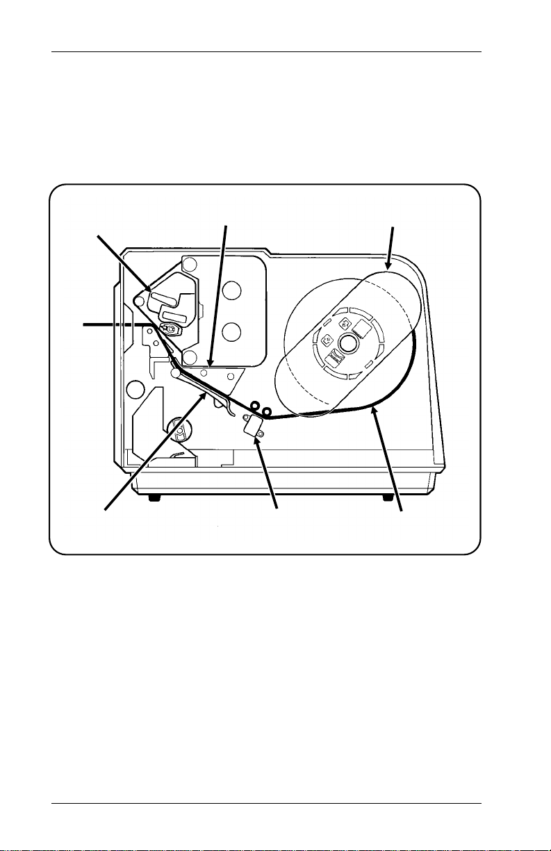
2. Loading Suppl y
14.
Turn the supply roll
countercloc kwise
to remove any
slack in the bac king paper. Your supply and backing paper
should be fed as shown.
Labels
Backing Paper
2-13
Loading Supplies
Page 22

9445 Equipment Manual
15.
To adjust for wide or narrow supply, turn the supply width
Adjustment Knob to:
NARROW
•
WIDE
•
NOTE:
Printhead
Lever
Supply Width
Adjustment
Knob
for supply
for supply
two inches in width or smaller
greater than two inches in width.
Be sure the adjustment knob snaps back into
place after you turn it.
16.
Turn the printhead lever to the right to lock the printhead.
2-14
Page 23

17.
Turn the printer on. If you are:
•
replacing the supply with a new roll of the same size,
press f to align the printer.
•
changing supply size, adjust the supply sensor. See
"Adjusting the Supply Sensor" later in this section.
2. Loading Suppl y
NOTE:
Before you print, be sure the menu supply type
setting matches your supply type (e.g. Black
Mark/Die C u t). See your Operator’s Handbook to
set supply options.
CAUTION
Turning the printer on and off rapidly can cause it to
malfunction. If you have turned the printer on (or off), wait
ten seconds before turning it back off (or on).
Loading Supplies
2-15
Page 24

9445 Equipment Manual
Loading Fan-Fold Supply
The 9445 has the ability to print fan-fold supply with the
optional fan-fold printer cover. If your printer does not have a
fan-fold slot, contact Monarch Service to order a fan-fold
printer cover.
To load fan-fold supply:
1.
Open the front panel.
2.
Open the printhead by turning the printhead lever to the
left.
3.
Fan all four sides of the supply stack and straighten any
curved or bent corners. This will prevent supply from
sticking together and causing feed jams.
4.
Place the supply approximately one fan-fold length behind
the printer, label side up.
Printhead
Exit
Chute
5.
Feed the supply through the slot in the back of the printer
Printhead
Lever
Lower
Supply
Guide
Upper Supply
Guide
length from printer
Out-of-Stock
Switch
Space supply at
least one fan-fold
Slot
and past the out-of-stock switch.
2-16
Page 25

2. Loading Suppl y
6.
With one hand, hold down the lower supply guide. With
the other hand, feed the backing paper between the upper
and lower guides, past the printhead, and then out through
the exit chute.
Space supply at
least one fan-fold
length from printer
Box for
fan-fold
labels
7.
Close the printhead by turning the printhead lever to the
right.
8.
Place an empty box below the printer’s exit chute to catch
the labels as they are printed.
NOTE:
Check the stack of printed labels a few times during
the print job to make sure the labels fold at the same
points at which they were folded before printing. If
you remov e som e or all of the printed labels, check
that the order of the folds is correct before you
resume printing.
Box of new
labels
Loading Supplies
2-17
Page 26

9445 Equipment Manual
Adjusting the Supply Sensor
The supply sensor controls how much supply feeds between
tags or labels. The sensor reads blac k m arks or feed apertures.
To read black marks or apertures, the sensor must be aligned
with the black mark or aperture on the tag. Otherwise, you’ll
see an error message when you try to print a batch.
When moving the sensor, tur n the sensor adjustment knob:
CLOCKWISE
•
edge of the supply.
COUNTERCLOCKWISE
•
the inside edge of the supply.
to move the sensor away from the inside
to move the sensor toward
2-18
Sensor
Adjustment
Knob
Page 27

2. Loading Suppl y
Die cut supply requires no sensor adjustment.
1.
Do one of the following:
For black mark supply, turn the sensor adjustment knob
counterclockwise
until it stops. Do not force the knob.
For feed apertures, turn the sensor adjustment knob
counterclockwise
clockwise
•
Measure from the edge of the supply to the center of
as determined below.
until it stops. Then turn the knob
the aperture.
•
Subtract 1/8 inch (3.1 mm) from the measurement.
•
Multiply the result by 36 (if you are measuring in millimeters, multiply by 1.41).
For example, if the measurement to the aperture center
is 3/8 inch (9.5 mm), turn the knob 9 turns to center the
sensor.
Sensor
Adjustment
Knob
2.
Close the front panel.
Loading Supplies
2-19
Page 28

9445 Equipment Manual
Adjusting the On Demand Sensor
The On Demand sensor stops the printer between tags or
labels when you print in the On Demand mode. The sensor
detects the presence of supply in the exit chute of the printer.
When you remov e the tag or label, another tag or label prints.
On Demand
Sensor
NOTE:
The On Demand sensor must be positioned over a
white or light area on the supply. If it is positioned
over a dark area, the entire batch may pr int before the
printer stops.
You can adjust the On Demand sensor either right or left by
pushing it with your finger.
2-20
Page 29

3. Loading a Ribbon
There are two types of supplies:
Thermal Direct
Thermal T ransfer
NOTE: DO NOT
supplies.
When installing a ribbon, remember
•
Ribbons may catch on supplies left in place.
•
Supplies can misalign the ribbon as you move the
supply up to the feed mark.
•
The width of your ribbon must closely match the width
of your supply.
To install a ribbon roll, refer to "Loading a Ribbon Roll," later in
this chapter. To install a ribbon cassette, refer to "Loading a
Ribbon Cassette," later in this chapter.
specially treated thermal supplies that
don’t use a ribbon for printing.
standard supplies that require a ribbon
for printing.
load a ribbon when printing on thermal direct
3-1
Loading a Ribbon
Roll
Page 30

9445 Equipment Manual
Loading a Ribbon Roll
To load a ribbon roll:
1.
Open the front panel.
2.
Turn the printhead lever to the left to release the printhead.
(Also see the supply loading figure inside the front panel.)
NOTE:
Printhead
Lever
Tab
Upper
Guide
If the printer has supplies loaded for continuous
printing, pull the leading edge back to the upper
supply guide before loading the ribbon.
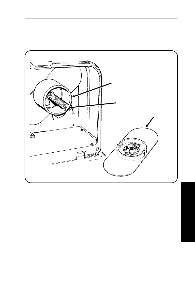
3.
Grasp the tab on the ribbon roll adapter and pull it out until
the adapter locks into the extended position.
3-2
Page 31

3. Loading a Ribbo n
4.
Pull the ribbon spool holders off. Remove the old ribbon (if
there is one).
5.
Be sure the thermal supply indicator is pointing upward.
NOTE:
Thermal
Supply
Indicator
Turn the thermal supply indicator to the right only
if you are going to use thermal direct supplies (no
ribbon).
Spool
Holders
6.
Load a new ribbon onto the lower spool shaft so the ribbon
unwinds
clockwise
.
Loading a Ribbon
Roll
3-3
Page 32

9445 Equipment Manual
7.
Guide the new ribbon around the rollers on the ribbon roll
adapter. Slide the upper spool onto the upper spool shaft.
Ribbon
Leader
Feed Mark
8.
Slide the ribbon spool holders against the spools.
9.
Turn the upper ribbon spool
tension to the ribbon.
Rollers
clockwise
Make sure the ribbon is tight but
Ribbon Roll
to add slight
not wrinkled or bunched.
10.
Slide the ribbon roll adapter in against the back wall of the
printer
NOTE:
To help slide the ribbon roll adapter in or out, it
may be necessary to increase or relax tension on
the ribbon by turning the spools.
3-4
Page 33

3. Loading a Ribbo n
11.
Turn the upper ribbon spool
clockwise
until the black part
of the ribbon is past the feed mark.
12.
If the printer has supplies loaded for continuous printing,
slide the supply up to the feed mark.
ribbon is correctly positioned
13.
Turn the printhead lev er to the right to move the printhead
Make sure the
.
against the ribbon and the supply.
14.
Close the front panel.
3-5
Loading a Ribbon
Roll
Page 34

9445 Equipment Manual
Loading a Ribbon Cassette
To load a ribbon cassette:
1.
Open the front panel.
2.
Turn the printhead lever to the left to open the printhead.
(Also see the supply loading figure inside the front panel.)
NOTE:
If the printer has supplies loaded for continuous
printing, pull the leading edge back to the upper
guide before loading the ribbon cassette.
3.
Remove the old ribbon cassette if necessary.
Printhead
Lever
3-6
Page 35

3. Loading a Ribbo n
4.
Remove the ne w ribbon cassette from the pac k age . Then
loosen ribbon from cassette as shown below.
3-7
Loading a Ribbon
Roll
Page 36

9445 Equipment Manual
5.
Guide the edge of the ribbon around the ribbon guide post.
6.
Place the cassette on the ribbon spools and push it
against the back wall. The spool lock will drop out.
Upper
Ribbon
Spool
Ribbon
Guide
Post
Printhead
Lever
7.
Turn the upper ribbon spool
Make sure the ribbon is not wrinkled or bunched
tight.
8.
Slide the supply up to the feed mark.
ribbon is correctly positioned
9.
While holding the cassette in place, turn the printhead
clockwise
.
until the ribbon is
Make sure the
lev er to the right to lock the printhead in place. Do not
force the lever.
10.
Close the front panel.
3-8
.
Page 37

4. Adjusting the Display
The intensity adjustment wheel is on the right side of the
keyboard. Rotate the wheel to lighten or darken the display.
Loading the Ribbon
Cassette
NOTE:
See you Operator’s Handbook for a description of the
keyboard k eys.
Intensity Adjustment Wheel
4-1
Page 38

9445 Equipment Manual
4-2
Page 39

5. Cleaning the Printhead and
Platen Roller
WARNING
Turn the power off and unplug the power cord before
cleaning.
1.
Open the front panel.
2.
Turn the printhead lev er to the left to open the printhead.
3.
Wind the supplies back onto the supply roll.
4.
Remove the ribbon cassette if one is loaded.
CAUTION
Cleaning the Printhead
and Platen Roller
DO NOT
printhead. This can damage the printhead and void your
warranty.
use sharp or abrasive materials to clean the
5-1
Page 40

9445 Equipment Manual
5.
Lightly moisten a cotton swab with alcohol and rub it back
and forth across the printhead. Clean the platen roller the
same way.
Printhead
Platen
Roller
6.
Reload the supply and ribbon cassette, if necessary, and
close the printhead.
7.
Turn the power on.
8.
Press f twice to realign the supply.
9.
If printing is not improved, call Monarch Service.
5-2
Page 41

Appendix A. Converting the
Keyboard for Table To p Use
1.
Lift the keyboard from the printer and place it on the table.
Converting the Keyboard
for Table Top Use
2.
Turn the keyboard over and remove the length of cord you
need.
3.
Slide a coil of the cord into the slot to hold it in place.
A-1
Page 42

9445 Equipment Manual
A-2
Page 43

Appendix B. Troubleshooting
If you cannot fix a problem, call Monarch service.
"Head Test Failure" Message
The 9445 performs a printhead test when you turn on the
printer. If the printhead test fails for any reason (bad
connection, bad dot), the printer displays "Head test failure."
If you receive this error:
1.
Press
2.
Print a test label (or one of the actual labels you plan to
print).
3.
Check for any visible print problems and do one of the
following:
•
•
•
•
e
to clear the message.
If there are no visible print problems, continue printing.
If there is a visible print problem in a bar code, call
Monarch Service. You can check the quality of your
bar code if you have a bar code verifier.
If there is a visible print problem that is not in a bar
coed, but is acceptable to you, continue printing.
If there is a visible print problem that is not in a bar
code and is not acceptable to you, call Monarch
Service.
Troubleshooting
B-1
Page 44

9445 Equipment Manual
Start-Up and Printing
Problem Action
Error message appears
during start-up.
"Check ribbon" message
appears.
Heavy printing. Adjust print contrast.
Light printing. Adjust print contrast.
No print. Change supply.
Turn power off, then on and try again.
If an error message appears again,
call Monarch Service.
Load a new ribbon roll or cassette.
Reload ribbon cassette.
Clean the printhead.
Change supply.
Reload ribbon cassette.
Change supply.
Reload ribbon cassette.
Correct the format in Format Entry
mode, or send a corrected format
online.
Change ribbon cassette.
Partially printed data. Change ribbon cassette.
Correct the format in Format Entry
mode or send a corrected format
online.
B-2
Page 45

Appendix B. Troubleshooting
Start-Up and Printing (continued)
Problem Action
Printed data becomes
misaligned.
Printed data wraps
around.
Printing shadows or
smears.
Voids in printing. Clean the printhead.
Recalibrate the printer. Select Printer
Options from the main menu, then
select Define Supply Type. Select
A)lign to recalibrate the printer.
Change supply.
Correct the format in Format Entry
mode or send a corrected format
online.
Clean the printhead.
Change supply.
Reload ribbon cassette.
Change supply.
Reload ribbon cassette.
B-3
Troubleshooting
Page 46

9445 Equipment Manual
Cutting
Problem Explanation
Cut length is more than
0.03 inches from tag
length.
"Knife jam" message
appears.
No cut action (or sound)
when c key is pressed.
No cut action when
key is pressed, but there
is a slight hum.
c
Call Monarch Service.
Paper is jammed in knife. Clear paper
and clean away any gum residue.
Knife out of position. Press S, then
press c twice to adjust the knife.
Then press
message.
Blades are worn. Call Monarch
Service.
Knife is out of position. Press S,
then press c twice to adjust the
knife. Then press
the message.
Knife is locked. Unlock knife.
Your printer is not equipped with a
knife.
Call Monarch Service.
e
twice to clear the
e
twice to clear
B-4
Page 47

Appendix C. Specifications
Printer
Height:
Weight:
Power:
Fuse:
Operating and
Storage limits:
Relative Humidity:
Display:
Printhead:
Printing Method:
14.5 inches (368.30 mm) without
keyboard; 17.7 inches (449.58 mm) with
keyboard.
35 lbs. (15.88 kg) packaged.
115 volts, 60 Hz. (standard) 220 volts,
50-60 Hz. (optional).
3 amps.
40°F to 104°F (4°C to 40°C).
5% to 90% (no condensation).
Liquid crystal display with 2 lines 32
characters per line (alphanumeric).
Thermal at 4.15 inches (105.41 mm)
wide 192 dots per inch (7.6 dots per
mm) 0.06 inch (1.5 mm) reserve
non-print area.
Thermal transfer (ribbon) or thermal
direct.
Appendix C
Ribbon T ype:
Ribbon Storage:
One-time carbon; black.
41°F to 95°F (5°C to 35°C).
leave ribbons in direct sunlight, high
temperatures, or high humidity.
DO NOT
C-1
Page 48

9445 Equipment Manual
Print Speed
With ribbon:
Print Speed
Without ribbon:
Supplies
•
Bar code toward top/bottom of tag
3.6 IPS
•
Bar code toward left/right side of tag
2.5 IPS
•
Bar code toward top/bottom of tag
3.6 IPS
•
Bar code toward left/right side of tag
2.5 IPS
*IPS = Inches per second
Supply T ypes:
Width
(without knife)
Width
(with knife)
Length
Supply Thickness:
Roll Diameter:
Thermal transfer stock or thermal direct
stock.
Minimum: 1.0 inch (25.4 mm)
Maximum: 4.5 inches (114.3 mm).
Minimum: 1.0 inch (25.4 mm)
Maximum: 4.0 inches (101.6 mm).
Minimum: 0.75 inch (19.05 mm)
Maximum: 8.0 inches (203.2 mm).
Tags or Labels: 0.006 to 0.010 inch
(0.152 to 0.355 mm).
Maximum 9.0 inches (228.6 mm)
C-2
Page 49

Page 50

For supplies, service, or assistance call:
TOLL FREE:
1-800-543-6650 (In U.S.A.)
1-800-263-4650 (In Canada)
Printed in U.S.A.
 Loading...