

Page 1
Monarch
9430RX
Printer
TC9430RXPM Rev. AA 10/05 ©2005 Paxar Americas, Inc. All rights reserved.
Page 2

Each product and program carries a respective written warranty, the only
warranty on which the customer can rely. Paxar reserves the right to make
changes in the product, the programs, and their availability at any time and
without notice. Although Paxar has made every effort to provide complete and
accurate information in this manual, Paxar shall not be liable for any omissions
or inaccuracies. Any update will be incorporated in a later edition of this
manual.
2005 Paxar Americas, Inc. All rights reserved. No part of this publication
may be reproduced, transmitted, stored in a retrieval system, or translated into
any language in any form by any means, without the prior written permission of
Paxar Americas, Inc.
Regulatory Compliance
Paxar products are designed to be compliant with the rules and regulations in
the locations into which they are sold and will be labeled as required. The
majority of RF devices are type approved and do not require the user to obtain
license or authorization before using the equipment. Any changes or
modifications to Paxar equipment not expressly approved by Paxar could void
the user authority to operate the equipment.
Radio Frequency Interference Requirements
This device complies with Part 15 of the FCC Rules. Operation is subject to the
following two conditions: 1) this device may not cause harmful interference, and
2) this device must accept any interference that may cause undesired
operations.
Radio Frequency Interference Requirements - Canada
This digital apparatus does not exceed the Class B limits for radio noise
emissions from digital apparatus set out in the Radio Interference Regulations
of the Canadian Department of Communications.
Le présent appareil numérique n’émet pas de bruits radioélectriques dépassant
les limites applicables aux appareils numériques de la classe B prescrites dans
le Réglement sur le brouillage radioélectrique édicte par le ministère des
Communications du Canada.
To comply with FCC and Industry Canada exposure requirements, if this device
is a hand-held portable device, it is approved for operation in a user’s hand
when there is 2.5 cm or more between the antenna and the user’s body; if this
device is a table-top device, it is approved for operation when there is 25 cm or
more between the antenna and the user’s body.
Page 3

European Economic Area
The European variant is intended for use throughout the European Economic
Area, and is compliant with the R&TTE directives; however, authorization for
use restricted as follows:
European standards dictate maximums radiated transmit power of 100 mW EIRP
and frequency range 2.400 –2.4835 GHz.
France, the equipment is to be restricted to the 2.4465 – 2.4835 GHz frequency
range.
Belgium outside, the equipment is to be restricted to the 2.460 – 2.4835 GHz
frequency range.
Operation in Italy requires a user license.
Trademarks
Paxar is a trademark of Paxar Corporation.
Monarch and 9430RX are registered trademarks of Paxar Americas, Inc.
Paxar Americas, Inc.
170 Monarch Lane
Miamisburg, OH 45342
Page 4

Page 5

Page 6

TABLE OF CONTENTS
INTRODUCTION........................................................................ 1-1
Duty Cycle ............................................................................. 1-1
Conventions Used in this Manual ............................................. 1-2
Control Characters .................................................................1-3
CONFIGURING THE PRINTER ...................................................2-1
Selecting the Operating Mode.................................................. 2-1
Setting the Print Contrast........................................................ 2-1
Setting the Power Mode .......................................................... 2-2
Checking the Battery Voltage ..................................................2-2
Request the printer statuses ................................................2-3
Using the Power-Off Timer ...................................................... 2-4
Supply Control Commands ...................................................... 2-5
Printer Responses............................................................... 2-6
Checking Version Information .................................................. 2-6
Printer/Device Communications ............................................... 2-7
Setting the DIP Switches......................................................... 2-8
Printer Pinouts .................................................................... 2-9
Miscellaneous Control Characters.......................................... 2-10
Table of Contents i
Page 7

CREATING AND PRINTING FORMATS ....................................... 3-1
Overview ............................................................................... 3-1
Creating Text Fields ............................................................... 3-1
Selecting Character Sets ..................................................... 3-2
Selecting a Font .................................................................. 3-3
Using Underline Characters ................................................. 3-4
Selecting the Line Spacing................................................... 3-5
Creating Graphic Fields .......................................................... 3-5
Using Data Stream Graphics ................................................ 3-6
Using Compressed Graphics ................................................ 3-7
Using Flash Memory Graphics .............................................. 3-8
Creating Bar Code Fields ........................................................ 3-9
Specifying Particular Bar Codes ......................................... 3-10
Positioning Fields ................................................................. 3-12
USING THE MAGNETIC CARD READER..................................... 4-1
Magnetic Card Specifications .................................................. 4-1
Error Messages................................................................... 4-3
QUICK REFERENCE ................................................................ A-1
Choosing a Font .....................................................................A-1
Choosing a Bar Code ..............................................................A-1
Printing Graphics....................................................................A-2
Supply Control Commands ......................................................A-2
Font Modification....................................................................A-3
Configuring the Printer............................................................A-3
Using the Magnetic Card Reader .............................................A-3
ii Table of Contents
Page 8

MODIFYING STANDARD FONTS............................................... B-1
Standard Fonts.......................................................................B-1
Modifying Fonts......................................................................B-1
Defining New Characters.........................................................B-2
Selecting Character Sets.........................................................B-3
Loading New Characters .........................................................B-4
Saving Modified Fonts.............................................................B-4
BLUETOOTH RF COMMUNICATION ....................................... C-1
Setting the Communications Parameters ................................. C-1
Manual Power Off .................................................................. C-2
INDEX .......................................................................................I-3
Table of Contents iii
Page 9

iv Table of Contents
Page 10

INTRODUCTION
1
The Monarch 9430RX printer control language contains a variety of
commands to
♦ create and print formats.
♦ configure the printer.
♦ enable specific printer features.
You download these commands in a data stream from another device. This
manual describes the printer's control language.
Duty Cycle
The printer is designed to print up to 1000 inches per day. The average print
rate is 1 inch every 10 seconds at a text character print density of 25% (i.e.,
one character printed out of every four positions). Bar codes and graphics are
more dense (print with more dots) than text and may need a lower duty cycle.
In high temperature environments, pause the printer for one minute after every
four (4) inches printed. If the duty cycle is exceeded, the printer may not print
all of the information that was sent to it.
Introduction 1-1
Page 11
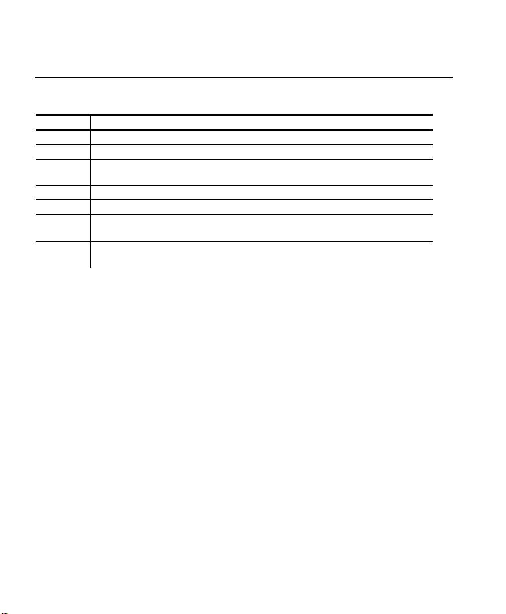
Conventions Used in this Manual
Following are the conventions used in the syntax descriptions of each
command.
Symbol Description
-
< >
' '
( )
# #
ESC
CR-LFNAK
These conventions make it easier for you to read the commands' syntax
descriptions. They are not part of the data streams. For example,
ESC-'F1' may be the syntax description, but the data stream should contain
1B for ESC. Also, - and ' (and other such characters described here) are not
part of the data stream.
For values not enclosed within single quotation marks, enter the value shown
while pressing ALT on the keyboard.
Separates items in the command sequence.
Indicates a variable with a single-byte value.
Indicates the value is a literal. Enter the value as it appears or
use the ASCII hex values for the same characters.
Indicates a variable of any length.
Indicates a variable of an exact length.
Indicates the beginning of a command sequence. Enter 1B hex
for this item.
Indicates the end of a response from the printer. In the
response, it is represented as 0D 0A 15 hex.
NOTE: The printer ignores commands with syntax errors.
1-2 Introduction
Page 12
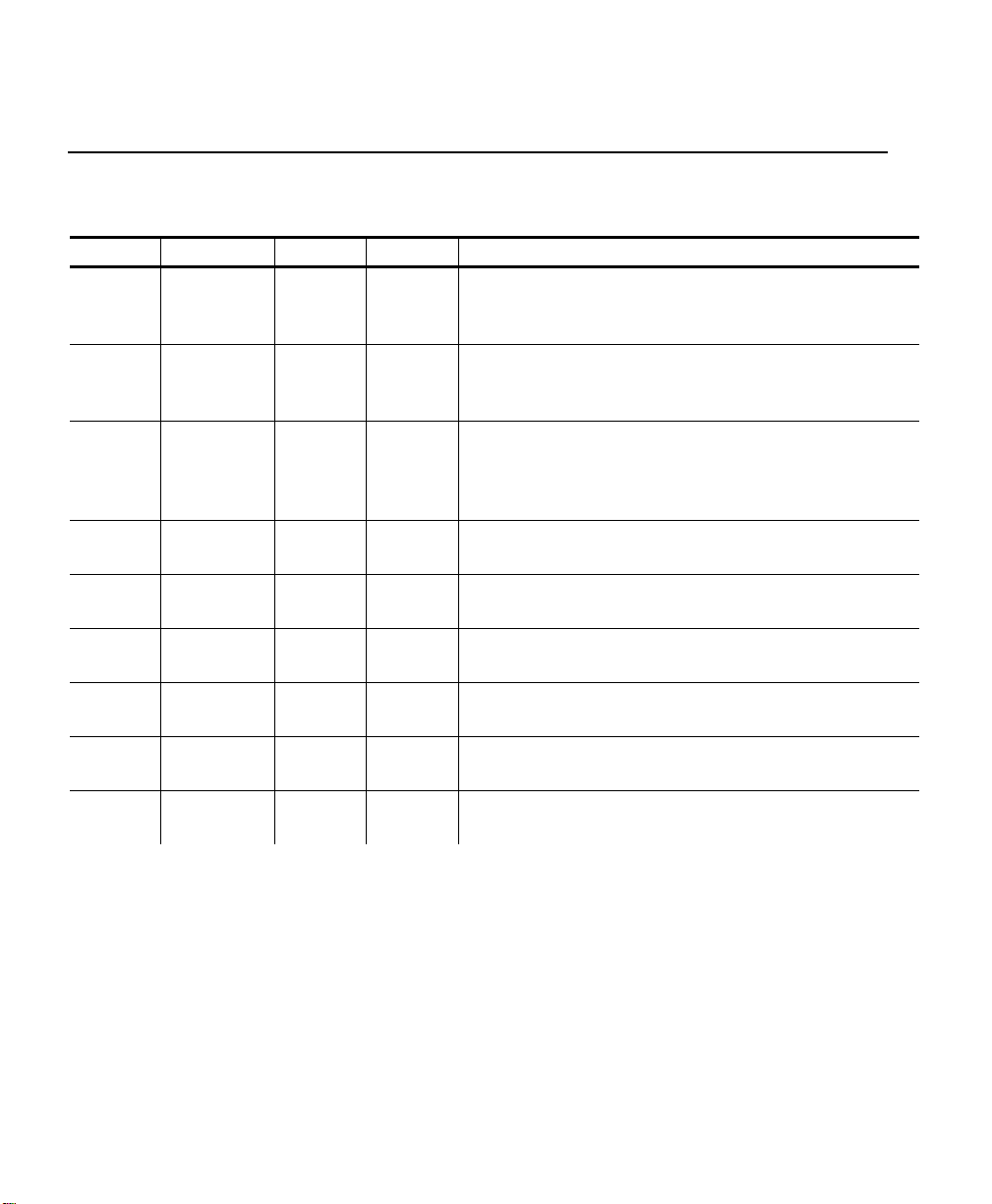
Control Characters
The following characters are reserved and used to control the printer. The
printer provides single-byte responses to the host of its status.
Char. Control Hex Dec Control Action
EOT ^D 0x04 04 End Of Text
Signals to the host device that the printer is
in idle mode and the print buffer is empty.
BS ^H 0x08 08 Backspace
Removes the previous character in the print
buffer.
HT ^I 0x09 09 Horizontal Tab
Advances to the next tab position (from the
following list) or to the beginning of the next
line: 5, 9, 13, 17, 21, 25, 29, 33, 37.
LF ^J 0x0A 10 Line Feed
Advances to beginning of next line.
VT ^K 0x0B 11 Vertical Tab
Advances 5 lines.
FF ^L 0x0C 12 Form Feed
Advances 10 lines.
CR ^M 0x0D 13 Carriage Return
Advances to beginning of next line.
SO ^N 0x0E 14 Shift Out
Switches to 36-column print mode
SI ^O 0x0F 15 Shift In
Switches to 57-column print mode.
Introduction 1-3
Page 13
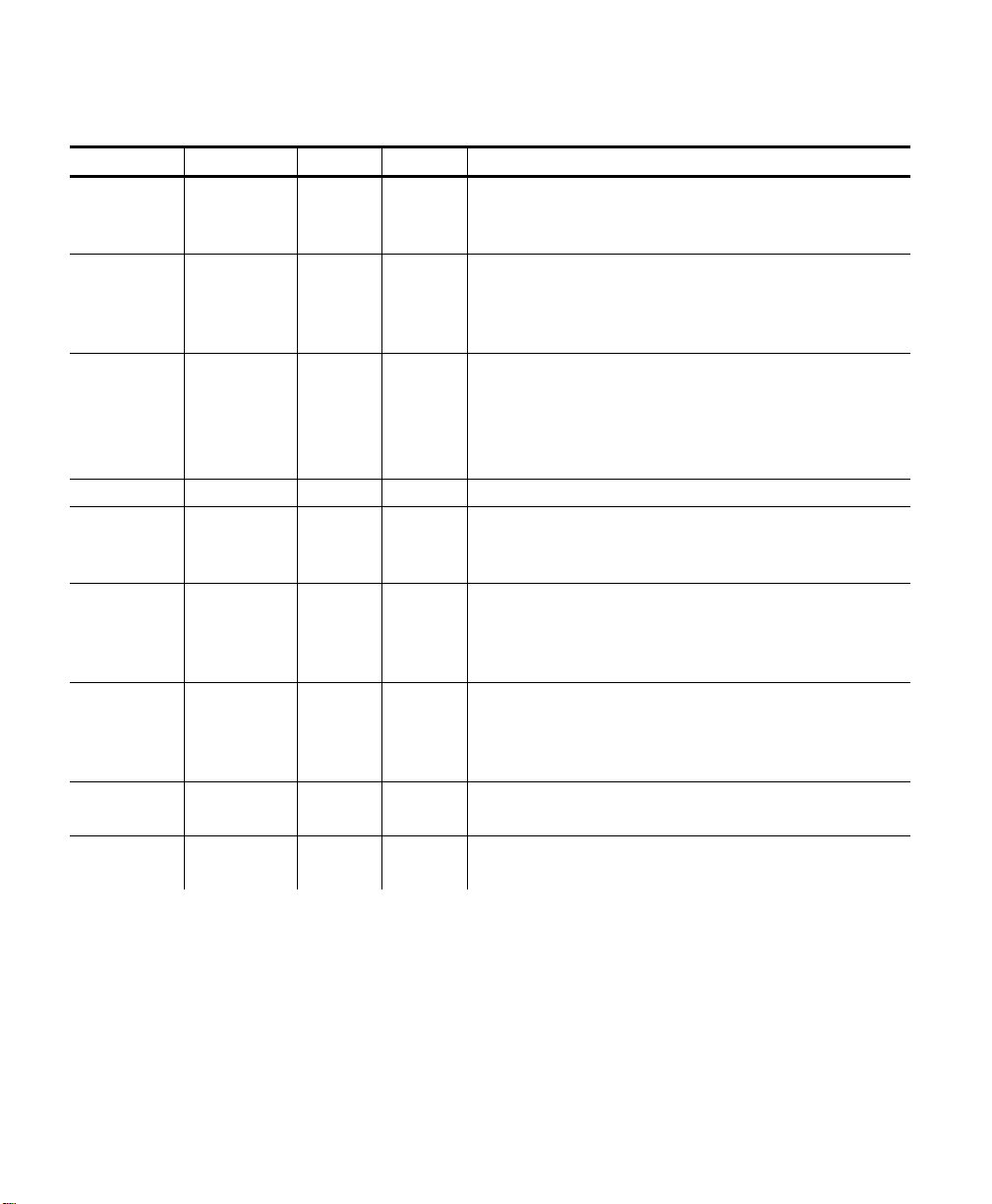
Char. Control Hex Dec Control Action
XON ^Q 0x11 17 Transmitter On
Signals that the device is ready to receive
data (can be sent by the printer or host).
AUXON ^R 0x12 18 Printer on
Signals to the host that the printer is
online. It is sent after initial power up,
clearing a supply jam, or a supply reload.
XOFF ^S 0x13 19 Printer receiver is off
Signals to the host that the print buffer is
full or an error has occurred.
Signals to the printer that the host’s
transmitter is off.
NORM ^T 0x14 20 Switches to 57-column print mode.
AUXOFF ^U 0x15 21 Printer is off
Signals to the host that the printer is out
of supply or has powered down.
CANCEL ^X 0x18 24 Cancel and reset printer
Resets the print buffer places the printer
in initial power-up mode with the default
settings.
ESC ^[ 0x1B 27 Escape
Indicates that the following characters are
part of a printer control language
command.
EXTEND ^\ 0x1C 28 Extended print
Prints characters double high.
EXTEND
OFF
^] 0x1D 29 Extended print off/Normal print
Prints characters at the normal height.
1-4 Introduction
Page 14

CONFIGURING THE PRINTER
There are several commands to configure the printer. You can include
these commands anywhere in a data stream. This chapter describes the
commands to configure the printer.
2
Selecting the Operating Mode
The printer works in either online or buffer mode. In online mode, the printer
prints characters as soon as they are received. In buffer mode, the printer
receives and stores characters, and then prints them upon receipt of an EOT
control character (4 hex).
Syntax ESC-‘cmdol’
ESC Starts the command language.
‘cmdol’ Online command. Options:
P# Selects online mode.
P$ Selects buffer mode.
Example ESC P#
Uses online mode. The printer starts printing as soon as it receives a
character.
Setting the Print Contrast
You can increase or decrease the print contrast for lighter or darker print. This
setting affects the print speed (the higher the contrast, the lower the speed and
vice versa). The print contrast also depends on the battery voltage.
Syntax ESC-<cmdpc>-<contrast>
ESC Starts the command language.
<cmdps> Print contrast command. Enter P.
<contrast> Print Contrast. Value can be between 0-9, where
0 is the highest contrast and 9 is the lowest
contrast. The default is 5.
Example ESC P9
Sets printer to lowest contrast (9) and fastest print speed.
Configuring the Printer 2-1
Page 15

Setting the Power Mode
The printer can operate in five different power modes, each using a different
number of printhead sections, which are groups of dots on the printhead. The
mode selected also affects the print speed (the more printhead sections used,
the faster the printer speed and vice versa).
Syntax ESC-<cmdpm>-<powmode>
ESC Starts the command language.
<cmdpm> Power mode command. Enter P.
<powmode> Power mode. The number of printhead sections to
use, specified in hex. Options:
1 Low - Use one printhead section, less than
1.0 Amp.
2 Medium - Use two printhead sections, less
than 2.0 Amps.
3 High - Use three printhead sections, less
than 3.0 Amps.
6 Very high - Use six printhead sections, less
than 9.0 Amps.
7 Auto Control - Dynamically choose the
number of printhead sections to use (1, 2,
3, or 6), depending on what is printed
(default).
Example ESC P2
Uses two printhead sections, which is less than 2.0 Amps.
Checking the Battery Voltage
The following commands/control characters check the battery’s voltage and
request statuses.
Syntax ESC-‘cmdvolt’
ESC Starts the command language.
‘cmdvolt’ Battery voltage command. Options:
P^ Prints the battery voltage.
P! Requests the battery voltage from the
printer.
Example ESC P^
Prints the battery voltage.
2-2 Configuring the Printer
Page 16

Request the printer statuses
You can request the print buffer, battery status, and magnetic card reader
status from the printer by sending 16 hex (Ctrl-V) to the printer.
The printer responds with
ESC-'B'-#pbchars#-CR-LF-ESC-'V'-#volts#-CR-LF-ESC'M'-#card#-CR-LF-NAK
ESC B Print buffer status.
#pbchars# The number of characters currently in the print
buffer, shown as four ASCII hex digits, which are
“OR’d” with 30 hex.
CR LF Carriage return and line feed.
ESC V Battery voltage status.
#volts# Four ASCII decimal digits (which are “OR’d” with
30 hex). The first three are the battery voltage
(form x.x).
The fourth character categorizes the voltage listed
to give it a reference. Values are 1-4, where 1 is
high and 4 is low.
CR LF Carriage return and line feed.
ESC M Magnetic card reader status.
#card# Four ASCII hex digits (which are “OR’d” with 30
hex) representing the time left before the printer
enters sleep mode.
CR-LF-NAK Indicates the end of a response from the printer.
You can send a print status request to the printer for print buffer status and the
magnetic card reader status by sending 2 hex (Ctrl-B)
Configuring the Printer 2-3
Page 17

Using the Power-Off Timer
The printer has a power-off timer to conserve battery life. After a specified
period of inactivity occurs, the printer goes into sleep mode.
The printer returns to normal mode when it starts receiving commands again,
but the countdown re-starts after every character received.
Before powering down, the printer sends AuXon then Xoff. See “Setting the
Communications Parameters” for descriptions of the dip switches and for
information about this feature.
Syntax ESC-<cmdpt>-<digit1><digit2>-CR
ESC Starts the command language.
<cmdpt> Power-off timer command. Enter M.
<digit1><digit2> Number of seconds for the inactivity period.
Options: 0 to 9. The first and second digits,
respectively, of the number of seconds to set the
inactivity period to. To disable the timer, set both
parameters to 0.
CR Carriage return.
NOTE: Be careful when using sleep mode with buffer mode. If there
is data in the print buffer when the printer goes into sleep
mode, you lose the data.
Example ESC MC CR
Sets the inactivity period to the default (20 seconds).
Example ESC M560 CR
Sets the inactivity period to 56 seconds.
Example ESC M000 CR
Disables the power-off timer.
2-4 Configuring the Printer
Page 18

Supply Control Commands
The commands in this section control how the printer uses black-mark supplies.
Look at your supply (distance between black marks, existence of any preprinted
text, etc.) before you begin. You may have to use the black mark search
command multiple times if the marks are farther apart than the maximum search
allows. To use these commands:
1. Set the sensitivity of the sensor search mechanism detecting the black
mark (ESC QQ command).
2. Move the supplies forward (ESC QF command) or backward (ESC QB or
ESC QJ commands) to find the black mark.
3. Wait for a response from the printer (found or not found).
4. Send a data stream with printing commands.
Syntax ESC-‘cmdbw’-<lines>
ESC-‘cmdos’-<lines>
ESC-‘cmdbfw’-<max>
ESC-‘cmdbbw’-<max>
ESC Starts the command language.
‘cmdbw’ Backward command. Enter QJ.
<lines> The number of lines to move the printer backwards
in 0.125 mm increments (in 00 hex – FF hex).
ESC Starts the command language.
‘cmdos’ Out of supply sensitivity command. Enter QQ.
<lines>- The number of lines to continue to print in
0.125mm increments (00 hex – FF hex) after
failing to detect a black mark. The default is 28
hex.
ESC Starts the command language.
‘cmdbfw’ Search for black mark forward command.
Enter QF.
<max> The maximum number of lines to move forward
(advance) in 0.25mm line increments
(in 00 hex – FF hex).
Configuring the Printer 2-5
Page 19

ESC Starts the command language.
‘cmdbbw’ Search for black mark backward command.
Enter QB.
<max> The maximum number of lines to move backward
in 0.25mm line increments (in 00 hex – FF hex).
Printer Responses
See the printer’s response to the black mark commands in the following table.
Command Response Description
ESC-'Q'-3F hex-3F hex-#high#-#low# Black mark found. ESC QR39
ESC QB35
ESC-'Q'-30 hex-30 hex-#high#-#low# Black mark not found
#high# The left digit of the hex number representing the
number of lines moved to find the black mark in
30 hex – 3F hex.
#low# The right digit of the hex number representing the
number of lines moved to find the black mark in
30 hex – 3F hex.
Checking Version Information
You can check the versions of both the printer’s hardware and firmware.
Syntax ESC-‘cmdfv’
ESC-‘cmdhv’
ESC Starts the command language.
‘cmdfv’ Request firmware version command. Enter P(.
ESC Starts the command language.
‘cmdhv’ Request hardware version command. Enter P).
2-6 Configuring the Printer
Page 20

Example ESC P(
The printer responds with:
ESC-'('-#version#-CR-LF-NAK
ESC ( Response from the firmware version request.
#version# Four ASCII characters representing the firmware
version.
CR-LF-NAK Indicates the end of a response from the printer.
Example ESC P)
The printer responds with:
ESC-')'-'103'-#version#-CR-LF-NAK
ESC ) Response from the hardware version request.
#version# An ASCII character representing the hardware
version.
CR-LF-NAK Indicates the end of a response from the printer.
Printer/Device Communications
Following are the printer’s communication values. The defaults are listed in
bold.
♦ Baud Rate – 2400, 9600, 19200, or 38.4K
♦ Stop Bits – 1 or 2
♦ Parity – None, Odd, or Even
♦ Data Bits – 7 or 8
♦ Flow Control – RTS/CTS (hardware) or XON/XOFF (software)
The printer and host cannot communicate unless they use the same
communication values. Additional communication specifications:
Word Length –10 or 11 bits Start Bit – 1 Signal Levels – RS232C
Mark or Logical 1 – -3 to -15VDC Space or Logical 0 – +3 to +15VDC
Auto Power Up – Positive signal on RTS input turns printer on.
Configuring the Printer 2-7
Page 21

Setting the DIP Switches
Use the DIP switches to set the RS232 communication, IrDA, and optional RF
values. To access the DIP switches, open the battery door and remove the
battery. Turn the printer upside down to easily read the DIP switches.
To activate the DIP switches, turn the printer off and then back on. Gently use
a plastic-tipped object to set the DIP switches. Do not use any metal object!
The communications interface settings must be set as defined in the table.
Select DIP switches 4 through 8 for RS232 and 6 through 8 for IrDA.
1 2 3 4 5 6 7 8
Communication
Interface
RS232 OFF OFF OFF
IrDA – Fixed 9600 ON ON OFF OFF OFF
IrDA – Variable Baud ON ON OFF ON OFF
Bluetooth® OFF OFF ON OFF OFF OFF OFF OFF
Baud Rate
38400 OFF OFF
19200 OFF ON
9600 ON OFF
2400 ON ON
Parity
None OFF OFF
Odd ON OFF
Even ON ON
Printer Power
Auto Power Off * ON
Manual Power Off OFF
* The printer automatically turns off after 99 sec. (default) or the time set up by the
System Administrator.
2-8 Configuring the Printer
Page 22

Printer Pinouts
There is a port for a 6-Pin RJ25 data connector. It provides RS-232
communications and is located at the back of the printer. The six connections
provide the serial interface to the host. The table below lists the serial interface
signals and pinouts.
NOTE: Pins 1 and 3 must be set on at all times.
Pin # Description Input/Output Signal
3 Signal to printer from host Input RXD
2 Signal to host from printer Output TXD
6 Request to send from Host Input RTS
4 Clear to send from Printer Output CTS
1 and 5 Logic common COM
Following are the pin locations on the connector:
The following control characters are related to communications between the
printer and the host.
Char. Hex Control Action
AUXON 0x12
AUXOFF 0x15
XON 0x11
XOFF 0x13
Signals to the host that the printer is online. It is sent after
initial power up, clearing a supply jam, or re-loading supply.
Signals to the host that the printer is out of supply or has
powered down.
Transmitter On
Signals that the device is ready to receive data (can be sent by
the printer or host).
Printer receiver is off
Signals to the host that the print buffer is full or an error has
occurred. Signals to the printer that the host’s transmitter is off.
Configuring the Printer 2-9
Page 23

Miscellaneous Control Characters
You may need to use some of these miscellaneous control characters in your
data streams.
Char. Hex Control Action
BS 0x08 Removes the last character entered in the print buffer.
CANCEL 0x18
EOT 0x04
Re-initializes the printer. We recommend that you begin all data
streams with this command.
Sent by the printer to indicate the buffer is empty and the printer
is idle (End Of Text).
2-10 Configuring the Printer
Page 24

CREATING AND PRINTING
3
FORMATS
A format defines which fields appear and where the fields are printed on the
supply. Fields can contain text, graphics, and bar codes.
This chapter describes how to create a format.
Overview
To create a format:
1. Decide the information (fields) you want on your supply.
2. Draw a rough sketch of how you want the format to look. For example, a
graphic (graphic field) may appear at the top, followed by the name of your
organization (text field), followed by a list of items (text field) purchased.
Your format could be organized any number of ways.
NOTE: There are .157-inch no-print zones on the left and right sides of the
format, and a .7-inch no-print zone at the top of the format.
3. Create the data stream, based on your format’s design.
4. Add any commands to the data stream related to how the printer performs.
For example, at the data stream's beginning, enter the command to
initialize the printer (18 hex) or any supply control commands.
5. Send the data stream from the host to the printer.
Creating Text Fields
Text fields can contain letters, numbers, and symbols. To specify text for the
format, write the text directly to the printer. There is no special Text field
command. However, there are commands/control characters to select a
character set and font.
Creating and Printing Formats 3-1
Page 25

Selecting Character Sets
The printer comes with a default ASCII character set.
You can select either of two extended character sets: International or PC LineDraw.
These character sets are standard in the printer.
NOTE: You can modify the standard character sets/fonts. See Appendix B,
“Modifying Standard Fonts,” for more information.
Character Exceptions
Both character sets have missing characters. The
and
3-2 Creating and Printing Formats
, respectively; the character replaces .
and characters replace
Page 26

Syntax ESC-<cmdcs>-<chset>
ESC Starts the command language.
<cmdcs> Character set command. Enter F .
<chset> Character Set. Options:
1 Selects International (ANSI) characters
(default)
2 Selects PC Line-Draw (ASCII) characters.
Example ESC F1
Selects the International (ANSI) character set.
Selecting a Font
For your format’s text, select the font, its size, and style (normal or bold).
Syntax ESC-‘chheight’
ESC-<cmdf>-<font>
ESC-<cmdb>-<bold>
ESC Starts the command language.
‘chheight’ Character Height. Use EXTEND or EXTENDOFF.
1C hex Prints characters twice as high as
normal (EXTEND).
1D hex Prints characters at the normal
height (EXTENDOFF).
ESC Starts the command language.
<cmdf> Font command. Enter k.
<font> Font. Options:
0 Large Rotated (90 degrees clockwise)
1 Large Normal
2 Standard Bold (default)
3 Standard Normal
4 Reduced Bold
5 Reduced Normal
Creating and Printing Formats 3-3
Page 27

ESC Starts the command language.
<cmdb> Bold command. Enter U .
<bold> Enables or disables bold printing. Options:
0 Turn off bold printing.
1 Turn on bold printing.
Example ESC 1D hex
ESC k1
ESC U0
This example uses the International (ANSI) character set, prints characters at
the normal height, uses the Large Normal font, and disables bold printing.
Using Underline Characters
You can specify underlining for text on your format.
Syntax ESC-<cmdu>-<uline>-‘data’
ESC Starts the command language.
<cmdu> Underline command. Enter F .
<uline> Sets underline mode. Options:
w Turns on underline for all characters
following this command. Underline is used
until an ESC Fh command is received or
until the end of the current line.
h Turns off underline for all for all characters
following this command. No underline is
used until an ESC Fw command is
received or until the end of the current line.
‘data’ Enter the data to print in your format. Must be
enclosed within single quotation marks.
Example ESC Fw ‘12345’ ESC Fh ‘78910’ ESC Fw ‘3345’ CR
‘12345’
Turns on underline for characters 12345 and turns off underline for characters
78910. The printer prints:
12345
789103345
12345
3-4 Creating and Printing Formats
Page 28

Selecting the Line Spacing
You can change the line spacing between lines or before a line.
Syntax ESC-<cmdls>-num
ESC Starts the command language.
<cmdls>-num Line spacing command. Options:
a-num sets the line spacing between text
lines. Value for num is 0-10, in
increments of 0.125mm.
J-num sets the number of line feeds at the
beginning of a line. Value for num is
0-255, in increments of 0.125mm.
Example ESC a2
Sets the spacing between lines to 0.25mm.
Creating Graphic Fields
The printer can print bitmap graphics from
♦ data streams
♦ flash memory.
You use the same commands for both methods. However, if you use a data
stream, you must recreate the graphic every time you print it. If you save the
graphic in flash memory, you only create it once and retrieve it when you want
to print it.
You can also compress graphics.
You can also change the line spacing between lines or before a line. See
“Selecting the Line Spacing” in this chapter for more information.
Creating and Printing Formats 3-5
Page 29

Using Data Stream Graphics
Data stream graphics print one line at a time. These lines may contain data or
spaces. To create a line, you specify bits to turn off or on. Bits turned off
represent white space, and bits turned on represent part of the graphic. There
is a .125 mm gap between consecutive lines.
Syntax ESC-<cmdgl>-<lines1><lines2>-#data#
ESC Starts the command language.
<cmdgl> Graphic line command. Enter V .
<lines1><lines2> The first and second hexadecimal digits of the
number of lines to print.
#data# 72 hex bytes, indicating the dots to turn on or off.
For example, if a specified byte is FF, all the dots
are on. If it is 01, only one dot is on, and the
other 7 are off.
If you accidentally specify less than 72 bytes, the
printer does not print the graphic. If you specify
more than 72 bytes, a fatal error occurs.
NOTE: You do not directly specify the bits turned on or off. You
specify the bits in groups of eight by using two-digit hex
values.
Example ESC V 10
FFFFFFFFFFFFFFFFFFFFFFFFFFFFFFFFFFFFFFFFFFFFFFFFFFFF
FFFFFFFFFFFFFFFFFFFF
This line of code prints a solid horizontal line of dots. The data needs to be
entered on one line. Do not use line breaks to wrap the data. This data is
shown on several lines because of the font size and margins.
3-6 Creating and Printing Formats
Page 30

Using Compressed Graphics
You can compress the data in a graphic when it has repetitive values.
Syntax ESC-<cmdg>-<height>-<width>-<counter>-#data#
ESC Starts the command language.
<cmdg> Graphic command. Enter v.
<height> The number of dot lines in the following data
(entered as 8-bit data).
<width> The number of bytes per dot line (entered as 8-bit
data).
<counter> An indicator of how much data to process.
When <counter> is signed (and a positive number),
process the specified amount of data as with data
stream graphics. Otherwise, repeat the next byte
the specified number of times.
When <counter> is unsigned (and less than or
equal to 127), process the specified amount of
data as with data stream graphics. Otherwise,
repeat the next byte the specified number of times
(the specification being the difference between
counter and 256).
#data# The data in the graphic. 72 hex bytes, indicating
the dots to turn on or off. For example, if a
specified byte is FF, all the dots are on. If it is 01,
only one dot is on, and the other 7 are off.
NOTES: <counter> and <data> can repeat multiple times within one
command. For using Flash Memoroy Graphics, use the
graphic command above. However, <height> and <width> are
replaced by <low> and <high>. Do not use <counter>, but
make sure you still include the graphic’s #data#.
<low><high> The hex digits (listed backward) of a number
indicating how many lines to print. For example,
to print 10 lines, <low> is A, and <high> is 0.
#data# 72 hex bytes, indicating the dots to turn on or off.
For example, if a specified byte is FF, all the dots
are on. If it is 01, only one dot is on, and the
other 7 are off.
If you accidentally specify less than 72 bytes, the
printer does not print the graphic. If you specify
more than 72 bytes, a fatal error occurs.
Creating and Printing Formats 3-7
Page 31

Using Flash Memory Graphics
You can also use a graphic stored in flash memory. You are limited to one
graphic stored in memory at a time. Saving a graphic to flash memory when
there is already one there overwrites the previous one.
1. Remove the printer’s battery and wait several seconds.
2. Re-insert the battery and enter Download Mode immediately. It takes two
commands to enter Download Mode:
ESC DL
Have the host wait to send the second command until the printer
responds to the first command by returning a ‘?‘ character.
ESC LG0
3. Send the graphic one line at a time using the ESC-V command as described
in “Using Data Stream Graphics.”
ESC V 1 0
FFFFFFFFFFFFFFFFFFFFFFFFFFFFFFFFFFFFFFFFFFFFFFFFFFFFF
FFFFFFFFFFFFFFFFFFF
4. Save the graphic to flash memory using the following command:
ESC LG FF hex
When the printer receives the command, it returns a ‘D‘ character, and
begins the save. When the save is complete, the printer sends a ‘!’
character, and then an ‘X’ character every 500 milliseconds.
5. Remove the printer’s battery and wait several seconds before replacing it.
6. Print the flash memory graphic with the following command:
ESC Lg0
3-8 Creating and Printing Formats
Page 32

Creating Bar Code Fields
The printer can print the following bar codes, with or without human-readable
data.
♦ Code 39
♦ Codabar
♦ Interleaved 2 of 5
♦ Code 128 (UCC/EAN-128)
♦ UPC/EAN/JAN
Syntax ESC-<cmdbc>-<bctype>-<length>-<height>-‘data’
ESC Starts the command language.
<cmdbc> Bar code command. Options:
z Prints a bar code without human-readable
data.
Z Prints a bar code with human-readable
data.
<bctype> The type of bar code to print (values are the ASCII
representation, not hex). Options:
1 Code 39
2 Code 128 (UCC/EAN-128)
3 Interleaved 2 of 5
4 UPC/EAN/JAN
5 Codabar
<length> The data length, specified in hex (01 – FF). This
value is dependent on the bar code you choose
with <bctype>. See “Specifying Particular Bar
Codes.”
<height> The bar code height, specified in hex, in
increments of .125 mm. <height> can be no
smaller than 14. For example, 14 = 2.5 mm,
15 = 2.625 mm, etc.
For UPC/EAN/JAN bar codes, the height you
specify includes a 1.25 mm drop bar pattern after
the bar code.
‘data’ The data for the bar code. It must equal <length>.
See “Specifying Particular Bar Codes” for data
restrictions, which vary by bar code.
Creating and Printing Formats 3-9
Page 33

Example ESC Z 3 08 hex 50 hex '12345678'
Prints an Interleaved 2 of 5 bar code, 10 mm high, containing 12345678 as the
data.
Specifying Particular Bar Codes
Values for the <length> and <data> parameters depend on the type of bar
code you choose with <bctype>.
Bar Code
Code 39
Interleaved 2 of 5 24 (maximum)
<length> <data>
12 (maximum) with
automatic centering
0-9, A-Z, -, (space), $, /,
+, and %
Pairs of numeric
characters (0-9)
UPC/EAN/JAN UPCA: 12
0-9
UPCE: 7
EAN/JAN-8: 8
EAN/JAN-13: 13
These lengths are fixed
and all include a check
digit.
Codabar
20 (maximum) plus start
and stop characters. The
printer adds the stop
character automatically.
Data: 0-9, $, -, :, /, ., and
+.
Start characters: a (the
default), b, c, or d.
Code 128 (UCC/EAN-128) Details
For Code 128 (UCC/EAN-128) bar codes, <length> can be a maximum of 18
(with alphanumeric/control code data) or 36 (if you use subset C and numeric
pairs).
The first character of <data> must specify the subset to use: A, B, or C (listed
as 87, 88, and 89 hex, respectively). The rest of the data can be all 256 ASCII
characters by using a combination of the subsets. The data must appear as
numeric pairs corresponding to the hex values for the ASCII character in
question.
Each subset enables the bar code to contain different characters. Subset A
uses 20-3F hex and 40-7F hex (read by a bar code scanner as 00-7F hex),
subset B uses 20-7F hex, and subset C uses 30-39 hex.
3-10 Creating and Printing Formats
Page 34

The following tables explain how to switch from one subset to another and use
the functions.
Character Subset A Subset B Subset C
80 hex
81 hex
82 hex*
83 hex
84 hex
85 hex
86 hex
Function 3 Function 3
Function 2 Function 2
Shift Shift
Switch to Subset C Switch to Subset C
Switch to Subset B Function 4 Switch to Subset B
Function 4 Switch to Subset A Switch to Subset A
Function 1 Function 1 Function 1
* A temporary, one character shift to another subset.
The following table describes the purpose of each function (listed in the
previous table).
Function
Number
Function 1 Uses reserved Code 128 characters (UCC/EAN128).
Function 2
Function 3 Initializes a bar code scanner.
Function 4
Purpose
Appends data (subsets A and B only). The result is not
readable by all bar code scanners.
Extends characters by adding 128 to the ASCII code. For
example, 'a' (97 decimal) is changed to 'β' (225 decimal) by
adding 128 to it. This function is unavailable in subset C.
Creating and Printing Formats 3-11
Page 35

Positioning Fields
You may need to use some of these supply positioning control characters to
position the fields on the format. The data stream can also write spaces to the
printer before it prints text to position a field.
You can also change the line spacing between lines or before a line. See
“Selecting the Line Spacing” in this chapter for more information.
NOTE: There are .157-inch no-print zones on the left and right sides of the
format, and a .7-inch no-print zone at the top of the format.
Char. Hex Control Action
CR 0x0D Carriage Return - Advances to beginning of next line.
LF 0x0A Line Feed - Advances to beginning of next line.
FF 0x0C Form Feed - Advances 10 lines.
NORM 0x14 Switches to 57-column print mode.
SI 0x0F Shift In - Switches to 57-column print mode.
SO 0x0E Shift Out - Switches to 36-column print mode
HT 0x09
VT 0x0B Vertical Tab - Advances 5 lines.
Horizontal Tab - Advances to the next tab position (from
the following list) or to the beginning of the next line:
5, 9, 13, 17, 21, 25, 29, 33, 37.
3-12 Creating and Printing Formats
Page 36

USING THE MAGNETIC CARD
34
READER
Optional. Your printer may have a magnetic card reader, which reads
up to three tracks of magnetically encoded data from cards conforming to the
ANSI/ISO 7810 and 7811 standards.
Magnetic Card Specifications
The card thickness is 0.76 mm (+/- 0.08 mm)
Track Position
Track 1
ISO1 (IATA)
Track 2
ISO2 (ABA)
Track 3
ISO3 (MINTS)
After reading the data, the printer returns the information to the host.
Following is a summary of what occurs when using the reader:
1. The host wakes up the printer by sending it some characters.
2. The printer responds with an XON character.
3. The device starts the reader (ESC M command). The green LED turns on.
4. The user swipes a card.
5. If the swipe was successful, the reader turns off and the printer sends the
data read. If an error occurs, the red LED turns on. If the reader times out,
the printer sends a message.
Recording
Density
210 BPI 79 Characters 7
75 BPI 40 Characters 5
210 BPI 107 Characters 7
Recording
Capacity
Number of
Data Bits
Using the Magnetic Card Reader 4-1
Page 37

Syntax ESC-<cmdmc>-#timer#-<tracks>-CR
ESC Starts the command language.
<cmdmc> Magnetic card command. Enter M. Prepares the
reader for a magnetic card swipe. The reader’s
LED turns on when the printer receives this
command, indicating it is waiting for the user to
swipe the card. On a successful swipe, the LED
turns off.
#timer# Sets the reader’s timer. If the user does not swipe
the card through the reader before the timer runs
out, an error occurs. Values are 00-99 (seconds).
00 disables the timer.
<tracks> The combination of tracks to read.
1 Track 1 only.
2 Track 2 only.
3 Track 3 only.
4 Tracks 1 and 2 together.
5 Tracks 2 and 3 together.
6 Tracks 1, 2, and 3 together.
CR Carriage return.
The reader responds to the read command with:
#trck#-(data)-'?'-CR-LF-NAK
#trck# Track indicator. Values are %/1/ (track 1), ;/2/
(track 2), and +/3/ (track3).
(data) The data read from the card. This field can be
empty. If an error occurs, this field contains an E
character and the error message text (see ”Error
Messages”).
? End of track character.
CR-LF-NAK Indicates the end of a response from the printer.
4-2 Using the Magnetic Card Reader
Page 38

Syntax 2 hex
2 hex (Ctrl-B) Requests the status of the print buffer and card
reader.
The printer responds with:
ESC-'B'-#pb#-CR-LF-ESC-'M'-#sleep#-CR-LF-NAK
#pb# The number of characters currently in the print
buffer, shown as four hex digits, which are “OR’d”
with 30 hex.
#sleep# Four ASCII hex digits (which are “OR’d” with 30
hex) representing the time left before the printer
enters sleep mode.
CR-LF-NAK Indicates the end of a response from the printer.
Example ESC C
Cancels the reading process.
Error Messages
The following data is returned when an error occurs with the magnetic card
reader. When an error occurs, the reader’s LED blinks once.
'%'-'E,'-#error#-','-(text)-CR-LF
Indicates an error occurred.
% and + Start of track characters.
E Indicates an error occurred.
#error#,(text) Error number and corresponding text.
05 Timeout Expired.
07 Invalid Track Number.
08 Unsupported Track selected.
09 Cancel Request.
CR-LF Carriage return and line feed.
Set the value for the timer long enough to allow the swipe, but short enough not
to allow multiple swipes. If multiple swipes are done (with different cards) and
each uses different tracks to store data, the data sent back to the host is a
mixture from the two cards.
Using the Magnetic Card Reader 4-3
Page 39

4-4 Using the Magnetic Card Reader
Page 40

QUICK REFERENCE
For more detailed information about each command, see the previous
chapters.
Choosing a Font
Syntax
ESC k5
ESC k4
ESC k3
ESC k2
ESC k1
ESC k0
ESC F1
ESC F2
ESC U1
ESC U0
ESC Fw
ESC Fh
ESC a <num>
ESC J <num>
Character size
(WxH)
8x21 Reduced Normal
9x21 Reduced Bold
10x21 Standard Normal
12x21 Standard Bold
16x21 Large Normal
14x16 Large Rotated (90 degrees clockwise)
Font Name/Action
Selects the International character set.
Selects the PC Line-Draw character set.
Enables bold printing.
Disables bold printing.
Enables underline mode.
Disable underline mode.
Selects the dot line spacing between
printed lines.
Performs a line feed.
A
Choosing a Bar Code
Syntax Printer Action
ESC z <bctype> <length> <height> <data>
ESC Z <bctype> <length> <height> <data>
Prints a bar code
without humanreadable data.
Prints a bar code with
human-readable data.
Quick Reference A-1
Page 41

Printing Graphics
Syntax Printer Action
ESC P#
ESC P$
ESC V <lines1> <lines2>
#data#
ESC v <height> <width>
<counter> #data#
ESC DL
ESC LG0
ESC LG FF hex
ESC Lg0
Selects online mode, characters are printed
when received.
Selects buffer mode, characters are printed
on receipt of an EOT character.
Prints a line from a data stream graphic.
Specifies a line of a compressed graphic
Command
Performs step 1 of entering flash memory
graphic download mode.
Performs step 2 of entering flash memory
graphic download mode.
Saves a flash memory graphic.
Prints the stored flash memory graphic.
Supply Control Commands
Syntax Printer Action
ESC QJ <lines>
ESC QQ <lines>
ESC QF <max>
ESC QB <max>
Moves the supply backward in .125mm
increments, looking for a black mark.
Specifies the number of lines to continue
printing after failing to find a black mark.
Moves the supply forward in .25mm
increments, looking for a black mark.
Moves the supply backward in .25mm
increments, looking for a black mark.
A-2 Quick Reference
Page 42

Font Modification
Syntax Printer Action
ESC DAO
ESC DX <charfont>
ESC D <font> <code>
<matrix>
Selects characters from the ASCII character
set.
Selects extended characters from the PC LineDraw or International character sets.
Loads a character at a particular position.
Configuring the Printer
Syntax Printer Action
ESC P^
ESC P <value>
ESC Mnn0 CR
ESC C
ESC P!
ESC P(
ESC P)
CTRL B
CTRL V
Prints the battery voltage.
Sets the power mode (when <value> is hex).
Sets the print contrast (when <value> is
decimal).
Sets the power down timer to nn seconds
(000 = disable timer).
Resets auto power down to 20 seconds.
Requests the printer’s battery voltage.
Queries the printer firmware version.
Queries the printer hardware model.
Print status request for buffer and magnetic
card reader.
Battery status request for buffer, battery
voltage, and magnetic card reader.
Using the Magnetic Card Reader
Syntax Printer Action
ESC M' #timer#
<tracks> CR
Prepares the reader for a card swipe.
Quick Reference A-3
Page 43

A-4 Quick Reference
Page 44

MODIFYING STANDARD FONTS
You can modify the printer’s standard fonts by redefining the characters.
NOTE: Each time you modify a font, it replaces the current font
definition. The only way to return to the default font is to reload the
original definition.
B
Standard Fonts
The following fonts are standard in the printer. Standard Bold is the default.
Before you start any modifications, note the maximum size of characters in the
font you want to use.
Font Name Pitch
Reduced Normal 24 CPI normal 72 8x23 ESC k5
Reduced Bold 21 CPI normal 63 9x23 ESC k4
Standard Normal 19 CPI normal 57 10x23 ESC k3
Standard Bold 16 CPI normal 48 12x23 ESC k2
Large Normal 12 CPI normal 32 16x23 ESC k1
Large Rotated
(90 degrees
clockwise)
13 CPI rotated
Columns
per Line
32 (rows
per line)
Character
Size (WxH)
14x16 ESC k0
Syntax
Modifying Fonts
To modify a font:
1. Define a new character.
2. Select a character set to modify.
3. Load the new character.
4. Save the modified font.
Modifying Standard Fonts B-1
Page 45

Defining New Characters
You must define each new character separately, performing the following
procedure for each one.
1. Define the character in a matrix. The matrix size depends on the font you
select (see “Standard Fonts”). Think of the matrix as a bitmap showing
the character’s design. Following is an example.
Left Byte Right Byte
7 654 3 2 1076543210
NOTE: Leave at least one column blank to the character’s right so character
strings do not run together.
2. Translate each line into two bit sequences (left byte/right byte), where an
empty square is 0, and a filled-in square is a 1. For example, the second
line from the top is 00000000 01000000.
3. Convert each bit sequence into two hex characters. For example, the
second line from the top is 00 40.
B-2 Modifying Standard Fonts
Page 46

Selecting Character Sets
Before selecting a character set, remove the printer’s battery and wait several
seconds. Then, replace the battery and immediately use one of these
commands to select the character set to modify.
When it receives either of these commands, the printer copies the character set
to memory, then sends a ‘?’ character to the host.
The printer returns any characters not accepted as part of this command.
NOTE: Do not send any commands to the printer between turning it on and
selecting the character set.
Syntax ESC-‘cmdmd’-<chfont>
ESC Starts the command language.
‘cmdmd’ Modify font command. Options:
DA0 Selects characters from the ASCII
character set (33-127).
DX Selects characters and fonts from the
Extended PC Line-Draw or International
character set (128-255).
<chfont> Character Set and Font options:
0 Extended PC Line-Draw characters – Large
Rotated, Large Normal, and Standard Bold
fonts.
1 Extended PC Line-Draw characters –
Standard, Normal, Reduced Bold, and
Reduced Normal fonts.
2 International characters –Large Rotated,
Large Normal, and Standard Bold fonts.
3 International characters –Standard Normal,
Reduced Bold, and Reduced Normal fonts.
Example ESC DX2
Selects characters from the International Set (Large Rotated, Large Normal,
and Standard Bold) fonts.
Modifying Standard Fonts B-3
Page 47

Loading New Characters
This step allows you to load the new characters at a particular position in the
set.
Syntax <ESC>-<cmdlc>-<chfont>-<code>-#matrix#
ESC Starts the command language.
<cmdlc> Load character command. Loads a character at a
particular position. Enter D.
<chfont> Character Set and Font options:
0 PC Line-Draw characters (Large Normal
and Standard Bold)
Extended PC Line-Draw and International
Fonts (Large Normal, Standard Bold, and
Standard Normal)
1 PC Line-Draw Fonts (Standard Normal)
Extended PC Line-Draw and International
Fonts (Large Rotated, Reduced Bold, and
Reduced Normal)
2 PC Line-Draw Fonts (Reduced Bold and
Reduced Normal)
<code> The hex character code for the new character:
21 hex – 7F hex (PC Line-Draw) or
80 hex – FF hex (Extended PC Line-Draw and
International).
#matrix# The hex data from the matrix describing the new
character (see “Defining New Characters”).
Saving Modified Fonts
To save the modified font into flash memory, use ESC D FF hex. The printer
sends a ‘D’ character and then performs the save. When the fonts have been
saved, the printer sends a ‘!’ character to the host. Then, it sends an ‘X’
character every 500 milliseconds.
Next, remove the battery and wait several seconds before replacing it.
B-4 Modifying Standard Fonts
Page 48

BLUETOOTH® RF
C
COMMUNICATION
This printer has been electronically modified to extend the life of the
battery due to the current demands of Bluetooth RF communication. The printer
can be set to operate in either the MANUAL POWER OFF or AUTO POWER
OFF mode of operation.
To use Bluetooth, make sure the DIP switches are set as follows:
1 2 3 4 5 6 7 8
Bluetooth OFF OFF ON OFF OFF OFF OFF OFF
Setting the Communications Parameters
Bluetooth RF communication occurs at 38.4Kb/sec and parity none. To access
the DIP switches, open the battery door and remove the battery. See “Setting
the DIP Switches” in Chapter 2 for the proper location of the following DIP
switch settings.
DIP switch #4 = OFF and DIP switch #5 = OFF for 38.4Kb/sec
DIP switch #6 = OFF and DIP switch #7 = OFF for parity none
Manual Power Off
When using RF wireless communication, turn the printer on by pressing the ON
switch located on the left side of the printer. The printer remains active waiting
for the wireless print command. Pressing the ON switch again turns the printer
OFF. For each wireless use, turn on the printer again by pressing the ON
switch. Operating in this way greatly extends the life of the battery.
Operating with dip switch #8 ON means that the printer automatically turns off
after 99 sec. (default) or the time set up by the System Administrator. This
places the highest current demand from the battery resulting in reduced battery
charge life. It is recommended using the universal wall charger for additional
trickle charging to the battery to keep it fully charged.
If you want to leave the printer on for continuous operation (MANUAL POWER
OFF), set the DIP switch #8 to OFF.
DIP switch #8 = OFF
Bluetooth® RF Communication-C-1
Page 49

C-2 Bluetooth® RF Communication
Page 50

INDEX
B
bar code
fields, creating, 3-11
specifying particular, 3-13
types available, 3-13
bar code field creation commands, 3-11
battery voltage, checking, 2-3
black mark supplies, 2-7
buffer mode, 2-1
C
character
defining new, B-2
exceptions, B-3
loading new, B-4
sets, selecting (creating text fields), B-3
commands
bar code field creation, 3-11
battery voltage checking, 2-3
character set selection, 3-3
formatting text, 3-5
magnetic card reader, 4-2
operating mode selection, 2-1
power mode setting, 2-3
power-off timer, 2-6
print contrast setting, 2-1
supply control, 2-7
version information checking, 2-8
communication parameters, 2-9
communications between the printer and
device, 2-9
compressed graphics, 3-8
sets, selecting (font modification), B-3
checking
battery voltage, 2-3
version information, 2-8
Codabar bar codes, 3-13
Code 128 (UCC/EAN-128 bar codes, 3-13
Code 39 bar codes, 3-13
command summary, 1-1
contrast, print, 2-1
control characters, miscellaneous, 2-13
control of supplies, 2-7
conventions in manual, 1-2
Index i
Page 51

creating
bar code fields, 3-11
formats, 3-1
graphic fields, 3-6
text fields, 3-2
resident, B-1
formats
definition, 3-1
printing and creating, 3-1
formatting text, 3-4
D
data stream graphics, 3-7
defining new characters, B-2
device/printer communications, 2-9
DIP switches, 2-8; C-1
duty cycle, 1-1
E
errors, magnetic card reader, 4-3
exceptions, character, 3-3
F
fields
bar code, 3-11
graphic, 3-6
positioning, 3-15
text, 3-2
flash memory graphics, 3-10
font modification procedure, B-1
fonts
modified, B-4
G
graphics
data stream, 3-7
fields, 3-6
flash memory, 3-10
graphics, compressed, 3-8
H
hardware version, 2-9
I
Interleaved 2 of 5 bar codes, 3-13
introduction, 1-1
L
loading new characters, B-4
M
magnetic card reader
errors, 4-3
using, 4-1
manual, conventions in, 1-2
ii Index
Page 52

mode
buffer, 2-1
online, 2-1
operating, 2-1
power, 2-3
modification of fonts, procedure, B-1
modifying resident fonts, B-1
O
online mode, 2-1
operating mode, selecting, 2-1
P
pinouts of the printer, 2-12
positioning fields, 3-15
power mode, setting, 2-3
power-off timer, using, 2-6
R
resident fonts, modifying, B-1
responses (supply control), 2-8
S
saving modified fonts, B-4
selecting
character sets (creating text fields), 3-3
character sets (font modification), B-3
operating mode, 2-1
setting
DIP switches, 2-8; C-1
power mode, 2-3
print contrast, 2-1
supplies, black mark, 2-7
supply control commands, 2-7
print contrast, setting, 2-1
printer
supply control responses, 2-8
printer pinouts, 2-12
printer/device communications, 2-9
printing formats, 3-1
T
text
fields, creating, 3-2
formatting, 3-4
timer, power-off, 2-6
Index iii
Page 53

U
UPC/EAN/JAN bar codes, 3-13
using
data stream graphics, 3-7
flash memory graphics, 3-10
magnetic card reader, 4-1
power-off timer, 2-6
version information, checking, 2-8
voltage, battery, 2-3
iv Index
Page 54

Page 55

 Loading...