

Page 1

Monarch
Printers
F 9412
F 9413
F 9414
TC941XPM Rev. AB 3/00 ©1998 Monarch Marking Systems, Inc. All rights reserved.
Page 2

Each product and program carries a respective written warranty, the only
warranty on which the customer can rely. Monarch reserves the right to make
changes in the product, the programs, and their availability at any time and
without notice. Although Monarch has made every effort to provide complete
and accurate information in this manual, Monarch shall not be liable for any
omissions or inaccuracies. Any update will be incorporated in a later edition of
this manual.
©1997 Monarch Marking Systems, Inc. All rights reserved. No part of this
publication may be reproduced, transmitted, stored in a retrieval system, or
translated into any language in any form by any means, without the prior
written permission of Monarch Marking Systems, Inc.
WARNING
This equipment has been tested and found to comply with the limits for a Class A digital
device, pursuant to Part 15 of the FCC Rules. These limits are designed to provide
reasonable protection against harmful interference when the equipment is operated in a
commercial environment. This equipment generates, uses, and can radiate radio frequency
energy and, if not installed and used in accordance with the instruction manual, may cause
harmful interference to radio communications. Operation of this equipment in a residential
area is likely to cause harmful interference in which case the user will be required to correct
the interference at his own expense.
CANADIAN D.O.C. WARNING
This digital apparatus does not exceed the Class A limits for radio noise emissions from
digital apparatus set out in the Radio Interference Regulations of the Canadian Department
of Communications.
Le présent appareil numérique n’émet pas de bruits radioélectriques dépassant les limites
applicables aux appareils numériques de la classe A prescrites dans le Réglement sur le
brouillage radioélectrique édicte par le ministère des Communications du Canada.
Trademarks
Monarch is a registered trademark of Monarch Marking Systems, Inc.
Paxar is a trademark of Paxar Corporation.
9412, 9413, and 9414 are trademarks of Monarch Marking Systems, Inc.
Microsoft and MS-DOS are registered trademarks of Microsoft Corporation.
Windows is a registered trademark of Microsoft in the U.S. and other countries.
TrueType is a trademark of Apple Computer, Inc.
Hewlett-Packard is a registered trademark of Hewlett-Packard Company.
CG Triumvirate and CG Triumvirate Bold are trademarks of AGFA Corporation.
Adobe and Acrobat are trademarks of Adobe Systems Incorporated which may be registered in certain
jurisdictions.
Centronics is a registered trademark of Centronics Data Computer Corporation.
Monarch Marking Systems
P.O. Box 608
Dayton, Ohio 45401
Page 3

TABLE OF CONTENTS
GETTING STARTED. . . . . . . . . . . . . . . . . . . . . . . . . . . . . . . . . . . . . . . . . . . . . . . . . 1-1
About This Manual . . . . . . . . . . . . . . . . . . . . . . . . . . . . . . . . . . . . . . . . . . . . . . . 1-1
Before You Begin . . . . . . . . . . . . . . . . . . . . . . . . . . . . . . . . . . . . . . . . . . . . . . . . 1-3
Creating an MPCLII Format Packet . . . . . . . . . . . . . . . . . . . . . . . . . . . . . . . . . . 1-3
Daily Startup Procedures . . . . . . . . . . . . . . . . . . . . . . . . . . . . . . . . . . . . . . . . . 1-5
DESIGNING A FORMAT . . . . . . . . . . . . . . . . . . . . . . . . . . . . . . . . . . . . . . . . . . . . . 2-1
Starting with a Design. . . . . . . . . . . . . . . . . . . . . . . . . . . . . . . . . . . . . . . . . . . . . 2-2
Determining Format Contents . . . . . . . . . . . . . . . . . . . . . . . . . . . . . . . . . . . . . . 2-3
Determining the Print Area. . . . . . . . . . . . . . . . . . . . . . . . . . . . . . . . . . . . . . . . . 2-3
Drawing Rough Sketches. . . . . . . . . . . . . . . . . . . . . . . . . . . . . . . . . . . . . . . . . . 2-4
Using Supply Layout Grids. . . . . . . . . . . . . . . . . . . . . . . . . . . . . . . . . . . . . . . . . 2-4
Considering Field Types . . . . . . . . . . . . . . . . . . . . . . . . . . . . . . . . . . . . . . . . . . . 2-6
Considering Fonts. . . . . . . . . . . . . . . . . . . . . . . . . . . . . . . . . . . . . . . . . . . . . . . . 2-6
Using the Format Worksheet . . . . . . . . . . . . . . . . . . . . . . . . . . . . . . . . . . . . . . . 2-7
Filling in the Format Worksheet . . . . . . . . . . . . . . . . . . . . . . . . . . . . . . 2-7
CONFIGURING THE PRINTER . . . . . . . . . . . . . . . . . . . . . . . . . . . . . . . . . . . . . . 3-1
Setting Communication Parameters . . . . . . . . . . . . . . . . . . . . . . . . . . . . . . . . . 3-2
Using Parallel Communications . . . . . . . . . . . . . . . . . . . . . . . . . . . . . . . . . . . . . 3-2
Using MPCLII Conventions . . . . . . . . . . . . . . . . . . . . . . . . . . . . . . . . . . . . . . . . 3-3
MPCLII Punctuation. . . . . . . . . . . . . . . . . . . . . . . . . . . . . . . . . . . . . . . 3-3
Standard Syntax Guidelines . . . . . . . . . . . . . . . . . . . . . . . . . . . . . . . . 3-3
Using Online Configuration Packets. . . . . . . . . . . . . . . . . . . . . . . . . . . . . . . . . . 3-5
Configuration Packet Header. . . . . . . . . . . . . . . . . . . . . . . . . . . . . . . . 3-5
Configuration Syntax Guidelines . . . . . . . . . . . . . . . . . . . . . . . . . . . . . 3-8
Defining the System Setup Packet. . . . . . . . . . . . . . . . . . . . . . . . . . . . . . . . . . . 3-9
Defining the Supply Setup Packet . . . . . . . . . . . . . . . . . . . . . . . . . . . . . . . . . . 3-10
Defining the Print Control Packet . . . . . . . . . . . . . . . . . . . . . . . . . . . . . . . . . . . 3-11
Table of Contents i
Page 4

Defining the Monetary Formatting Packet . . . . . . . . . . . . . . . . . . . . . . . . . . . . 3-12
Defining the Control Characters Packet . . . . . . . . . . . . . . . . . . . . . . . . . . . . . 3-13
Resetting Control Characters . . . . . . . . . . . . . . . . . . . . . . . . . . . . . . 3-14
Defining the Communication Settings Packet . . . . . . . . . . . . . . . . . . . . . . . . . 3-15
Defining the Memory Configuration Packet. . . . . . . . . . . . . . . . . . . . . . . . . . . 3-16
Checking Current Buffer Sizes . . . . . . . . . . . . . . . . . . . . . . . . . . . . . 3-18
About Memory Buffers. . . . . . . . . . . . . . . . . . . . . . . . . . . . . . . . . . . . . . . . . . . 3-18
Buffer Worksheet. . . . . . . . . . . . . . . . . . . . . . . . . . . . . . . . . . . . . . . . 3-20
Buffer Allocation Considerations. . . . . . . . . . . . . . . . . . . . . . . . . . . . 3-21
Using Immediate Commands . . . . . . . . . . . . . . . . . . . . . . . . . . . . . . . . . . . . . 3-21
Enabling Immediate Commands. . . . . . . . . . . . . . . . . . . . . . . . . . . . 3-22
Sending Immediate Commands . . . . . . . . . . . . . . . . . . . . . . . . . . . . 3-22
Clearing Packets from Memory . . . . . . . . . . . . . . . . . . . . . . . . . . . . . . . . . . . . 3-24
Using the Font Packet . . . . . . . . . . . . . . . . . . . . . . . . . . . . . . . . . . . . . . . . . . . 3-25
DEFINING FIELDS . . . . . . . . . . . . . . . . . . . . . . . . . . . . . . . . . . . . . . . . . . . . . . . . . . 4-1
Defining the Format Header. . . . . . . . . . . . . . . . . . . . . . . . . . . . . . . . . . . . . . . . 4-2
Defining Text Fields . . . . . . . . . . . . . . . . . . . . . . . . . . . . . . . . . . . . . . . . . . . . . . 4-3
Defining Bar Code Fields. . . . . . . . . . . . . . . . . . . . . . . . . . . . . . . . . . . . . . . . . . 4-7
Defining Non-Printable Text Fields. . . . . . . . . . . . . . . . . . . . . . . . . . . . . . . . . . 4-12
Defining Constant Text Fields . . . . . . . . . . . . . . . . . . . . . . . . . . . . . . . . . . . . . 4-14
Defining Line Fields . . . . . . . . . . . . . . . . . . . . . . . . . . . . . . . . . . . . . . . . . . . . . 4-17
Line Types . . . . . . . . . . . . . . . . . . . . . . . . . . . . . . . . . . . . . . . . . . . . . 4-17
Defining Box Fields . . . . . . . . . . . . . . . . . . . . . . . . . . . . . . . . . . . . . . . . . . . . . 4-20
DEFINING FIELD OPTIONS . . . . . . . . . . . . . . . . . . . . . . . . . . . . . . . . . . . . . . . . . 5-1
Applying Field Options. . . . . . . . . . . . . . . . . . . . . . . . . . . . . . . . . . . . . . . . . . . . 5-1
Combining Field Options. . . . . . . . . . . . . . . . . . . . . . . . . . . . . . . . . . . 5-1
Option 1 (Fixed Data). . . . . . . . . . . . . . . . . . . . . . . . . . . . . . . . . . . . . . . . . . . . . 5-3
Option 4 (Copy Data). . . . . . . . . . . . . . . . . . . . . . . . . . . . . . . . . . . . . . . . . . . . . 5-4
Merging Fields. . . . . . . . . . . . . . . . . . . . . . . . . . . . . . . . . . . . . . . . . . . 5-5
Sub-Fields . . . . . . . . . . . . . . . . . . . . . . . . . . . . . . . . . . . . . . . . . . . . . . 5-5
ii Table of Contents
Page 5

Option 30 (Padding Data) . . . . . . . . . . . . . . . . . . . . . . . . . . . . . . . . . . . . . . . . . 5-6
Sample Use for Padding . . . . . . . . . . . . . . . . . . . . . . . . . . . . . . . . . . . 5-6
Option 31 (Calculate Check Digit) . . . . . . . . . . . . . . . . . . . . . . . . . . . . . . . . . . . 5-7
Option 42 (Price Field) . . . . . . . . . . . . . . . . . . . . . . . . . . . . . . . . . . . . . . . . . . . . 5-8
Option 50 (Bar Code Density) . . . . . . . . . . . . . . . . . . . . . . . . . . . . . . . . . . . . . . 5-9
Option 51 (PDF417 Security/Truncation) . . . . . . . . . . . . . . . . . . . . . . . . . . . . . 5-10
Option 52 (PDF417 Width/Length). . . . . . . . . . . . . . . . . . . . . . . . . . . . . . . . . . 5-11
Option 60 (Incrementing/Decrementing Fields) . . . . . . . . . . . . . . . . . . . . . . . . 5-12
Fixing the First Number in the Incrementing Sequence . . . . . . . . . . 5-12
Option 61 (Reimage Field) . . . . . . . . . . . . . . . . . . . . . . . . . . . . . . . . . . . . . . . . 5-13
Using Check Digits . . . . . . . . . . . . . . . . . . . . . . . . . . . . . . . . . . . . . . . . . . . . . . 5-14
Sum of Products Calculation . . . . . . . . . . . . . . . . . . . . . . . . . . . . . . . 5-15
Sum of Digits Calculation. . . . . . . . . . . . . . . . . . . . . . . . . . . . . . . . . . 5-16
PRINTING . . . . . . . . . . . . . . . . . . . . . . . . . . . . . . . . . . . . . . . . . . . . . . . . . . . . . . . . . . . 6-1
Defining the Batch Header . . . . . . . . . . . . . . . . . . . . . . . . . . . . . . . . . . . . . . . . . 6-3
Defining the Batch Control Field. . . . . . . . . . . . . . . . . . . . . . . . . . . . . . . . . . . . . 6-4
Defining Batch Data Fields. . . . . . . . . . . . . . . . . . . . . . . . . . . . . . . . . . . . . . . . . 6-5
Using Special Characters in Batch Data . . . . . . . . . . . . . . . . . . . . . . . 6-6
Merged or Sub-Fields . . . . . . . . . . . . . . . . . . . . . . . . . . . . . . . . . . . . . 6-6
Incrementing Fields . . . . . . . . . . . . . . . . . . . . . . . . . . . . . . . . . . . . . . . 6-6
Downloading Methods . . . . . . . . . . . . . . . . . . . . . . . . . . . . . . . . . . . . . . . . . . . . 6-7
Sequential Method. . . . . . . . . . . . . . . . . . . . . . . . . . . . . . . . . . . . . . . . 6-7
Batch Method. . . . . . . . . . . . . . . . . . . . . . . . . . . . . . . . . . . . . . . . . . . . 6-7
Batch Quantity Zero Method . . . . . . . . . . . . . . . . . . . . . . . . . . . . . . . . 6-7
Modifying Formats . . . . . . . . . . . . . . . . . . . . . . . . . . . . . . . . . . . . . . . . . . . . . . . 6-8
Optional Entry Method. . . . . . . . . . . . . . . . . . . . . . . . . . . . . . . . . . . . . 6-8
Creating DOS Batch Files for Downloading. . . . . . . . . . . . . . . . . . . . . . . . . . . . 6-9
STATUS POLLING . . . . . . . . . . . . . . . . . . . . . . . . . . . . . . . . . . . . . . . . . . . . . . . . . . 7-1
Inquiry Request (ENQ). . . . . . . . . . . . . . . . . . . . . . . . . . . . . . . . . . . . . . . . . . . . 7-2
Inquiry Response . . . . . . . . . . . . . . . . . . . . . . . . . . . . . . . . . . . . . . . . 7-2
Table of Contents iii
Page 6

ENQ Reference Table - Byte #2. . . . . . . . . . . . . . . . . . . . . . . . . . . . . . . . . . . . . 7-4
ENQ Reference Table - Byte #3. . . . . . . . . . . . . . . . . . . . . . . . . . . . . . . . . . . . . 7-6
Job Request. . . . . . . . . . . . . . . . . . . . . . . . . . . . . . . . . . . . . . . . . . . . . . . . . . . . 7-8
Job Response . . . . . . . . . . . . . . . . . . . . . . . . . . . . . . . . . . . . . . . . . . . 7-9
Job Status 0, 1, 2 Response Table (Status 1 Codes) . . . . . . . . . . . . 7-13
Job Status 0, 1, 2 Response Table (Status 2 Codes) . . . . . . . . . . . . 7-14
DIAGNOSTICS. . . . . . . . . . . . . . . . . . . . . . . . . . . . . . . . . . . . . . . . . . . . . . . . . . . . . . 8-1
Printing a Test Label. . . . . . . . . . . . . . . . . . . . . . . . . . . . . . . . . . . . . . . . . . . . . . 8-2
Using Data Dump. . . . . . . . . . . . . . . . . . . . . . . . . . . . . . . . . . . . . . . . . . . . . . . . 8-3
Troubleshooting Information . . . . . . . . . . . . . . . . . . . . . . . . . . . . . . . . . . . . . . . 8-4
If You Receive an Error Message . . . . . . . . . . . . . . . . . . . . . . . . . . . . 8-4
If the PC and Printer Aren’t Communicating. . . . . . . . . . . . . . . . . . . . 8-4
Calling Technical Support . . . . . . . . . . . . . . . . . . . . . . . . . . . . . . . . . . 8-5
ERRORS. . . . . . . . . . . . . . . . . . . . . . . . . . . . . . . . . . . . . . . . . . . . . . . . . . . . . . . . . . . . 9-1
Data Errors. . . . . . . . . . . . . . . . . . . . . . . . . . . . . . . . . . . . . . . . . . . . . . . . . . . . . 9-2
Communication Failures . . . . . . . . . . . . . . . . . . . . . . . . . . . . . . . . . . . . . . . . . 9-10
Data Formatting Failures . . . . . . . . . . . . . . . . . . . . . . . . . . . . . . . . . . . . . . . . . 9-12
Machine Faults. . . . . . . . . . . . . . . . . . . . . . . . . . . . . . . . . . . . . . . . . . . . . . . . . 9-13
PRINTER OPTIMIZATION . . . . . . . . . . . . . . . . . . . . . . . . . . . . . . . . . . . . . . . . . . 10-1
Adjusting the Print Quality . . . . . . . . . . . . . . . . . . . . . . . . . . . . . . . . . . . . . . . . 10-1
Reducing Imaging Time. . . . . . . . . . . . . . . . . . . . . . . . . . . . . . . . . . . . . . . . . . 10-3
General Format Tips and Hints . . . . . . . . . . . . . . . . . . . . . . . . . . . . . . . . . . . . 10-5
SAMPLES . . . . . . . . . . . . . . . . . . . . . . . . . . . . . . . . . . . . . . . . . . . . . . . . . . . . . . . . . . A-1
Sample UPCA Format Packet . . . . . . . . . . . . . . . . . . . . . . . . . . . . . . . . . . . . . A-2
Sample MaxiCode Packets . . . . . . . . . . . . . . . . . . . . . . . . . . . . . . . . . . . . . . . . A-3
Mode 0 Sample . . . . . . . . . . . . . . . . . . . . . . . . . . . . . . . . . . . . . . . . . . . . . . . . . A-4
Mode 2 Sample . . . . . . . . . . . . . . . . . . . . . . . . . . . . . . . . . . . . . . . . . . . . . . . . . A-5
Mode 3 Sample . . . . . . . . . . . . . . . . . . . . . . . . . . . . . . . . . . . . . . . . . . . . . . . . . A-6
Sample Compliance Packet. . . . . . . . . . . . . . . . . . . . . . . . . . . . . . . . . . . . . . . . A-7
Sample Format Packet . . . . . . . . . . . . . . . . . . . . . . . . . . . . . . . . . . . . . . . . . . A-10
iv Table of Contents
Page 7

FONTS . . . . . . . . . . . . . . . . . . . . . . . . . . . . . . . . . . . . . . . . . . . . . . . . . . . . . . . . . . . . . . B-1
Standard Fonts . . . . . . . . . . . . . . . . . . . . . . . . . . . . . . . . . . . . . . . . . . . . . . . . . B-1
Monospaced Font Magnification . . . . . . . . . . . . . . . . . . . . . . . . . . . . . . . . . . . . B-4
Proportional Font Magnification . . . . . . . . . . . . . . . . . . . . . . . . . . . . . . . . . . . . . B-6
CG Triumvirate Bold (9 pt.) . . . . . . . . . . . . . . . . . . . . . . . . . . . . . . . . . B-6
CG Triumvirate (6 pt.). . . . . . . . . . . . . . . . . . . . . . . . . . . . . . . . . . . . . . B-7
Locating the Font Number in a Font Packet. . . . . . . . . . . . . . . . . . . . . . . . . . . . B-8
SYMBOL SETS/CODE PAGES . . . . . . . . . . . . . . . . . . . . . . . . . . . . . . . . . . . . . . C-1
Supported Symbol Sets and Code Pages . . . . . . . . . . . . . . . . . . . . . . . . . . . . . C-1
Selecting a Symbol Set or Code Page. . . . . . . . . . . . . . . . . . . . . . . . . . . . . . . . C-1
Selecting the Internal Symbol Set . . . . . . . . . . . . . . . . . . . . . . . . . . . . C-1
Selecting the ANSI Symbol Set . . . . . . . . . . . . . . . . . . . . . . . . . . . . . . C-2
Selecting the 437 or 850 Code Page. . . . . . . . . . . . . . . . . . . . . . . . . . C-2
Using Code 128 Function Codes . . . . . . . . . . . . . . . . . . . . . . . . . . . . . . . . . . . . C-2
Entering Extended Characters . . . . . . . . . . . . . . . . . . . . . . . . . . . . . . . . . . . . . . C-2
Internal Symbol Set . . . . . . . . . . . . . . . . . . . . . . . . . . . . . . . . . . . . . . . . . . . . . . C-3
ANSI Symbol Set . . . . . . . . . . . . . . . . . . . . . . . . . . . . . . . . . . . . . . . . . . . . . . . . C-4
Bold Character Set . . . . . . . . . . . . . . . . . . . . . . . . . . . . . . . . . . . . . . . . . . . . . . . C-5
OCRA Character Set . . . . . . . . . . . . . . . . . . . . . . . . . . . . . . . . . . . . . . . . . . . . . C-6
Code Page 437. . . . . . . . . . . . . . . . . . . . . . . . . . . . . . . . . . . . . . . . . . . . . . . . . . C-7
Code Page 850. . . . . . . . . . . . . . . . . . . . . . . . . . . . . . . . . . . . . . . . . . . . . . . . . . C-8
ASCII to Hexadecimal Conversion Chart. . . . . . . . . . . . . . . . . . . . . . . . . . . . . . C-9
FORMAT DESIGN TOOLS. . . . . . . . . . . . . . . . . . . . . . . . . . . . . . . . . . . . . . . . . . . D-1
Online Configuration Worksheet . . . . . . . . . . . . . . . . . . . . . . . . . . . . . . . . . . . . D-2
Batch Worksheet . . . . . . . . . . . . . . . . . . . . . . . . . . . . . . . . . . . . . . . . . . . . . . . . D-3
Check Digit Worksheet. . . . . . . . . . . . . . . . . . . . . . . . . . . . . . . . . . . . . . . . . . . . D-4
Table of Contents v
Page 8

vi Table of Contents
Page 9

GETTING STARTED 1
Before you read this manual, review the printer information in the
Equipment Manual. This manual provides the necessary
information to design, write and print a Monarch® Printer Control
Language II (MPCLII) format. The following printers support this
type of format:
u
9412 (V. 1.0 or greater)
u
9413 (V. 1.0 or greater)
u
9414 (V. 1.0 or greater)
About This Manual
You do not need to be a programmer to use this manual, but you
must be familiar with creating text files and executing basic
MS-DOS® commands.
This chapter
u
describes the significant differences between the printers.
u
creates a sample MPCLII packet.
u
shows how to download a sample packet.
u
gives a list of daily procedures for operators.
Getting Started 1-1
Page 10
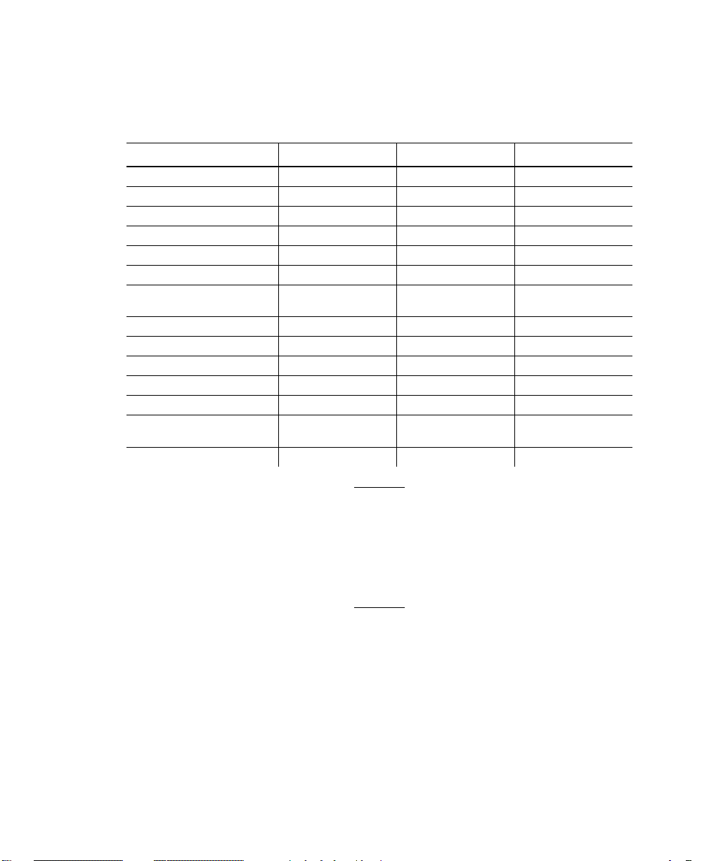
This features table gives an overview of each printer’s features.
While these printers are very similar, some differences in
operation and available options exist.
Feature 9412 9413 9414
Maximum print speed 2.0 ips 2.0 ips 2.5 ips
Maximum print area 2 in. x 6 in. 4 in. x 4 in. 4 in. x 6 in.
Location of Print Area Center Center Center
Supply Width 1.2 in. x 2.36 in. 1.2 in. x 4.25 in. 1.2 in. x 4.25 in.
Supply Length .38 in. x 6 in. .38 in. x 4.0 in. .38 in. x 6.0 in.
Power Up Mode Online Online Online
Feed Mode Continuous/
On-Demand
Ribbon Yes Yes No (direct only)
Supplies Tags or Labels Tags or Labels Tags or Labels
Field Number Range 0-999 0-999 0-999
Batch Separator Yes No Yes
2D bar codes Yes Yes Yes
Memory 128K battery-
backed RAM
Parallel Port Yes Yes Yes
Continuous/
On-Demand
128K batterybacked RAM
Continuous/
On-Demand
512K Flash
1-2 Getting Started
You can create larger images or store formats
if you purchase additional memory.
See "Defining Text Fields" in Chapter 4 for a
list of available fonts for your printer.
See Chapter 5, "Defining Field Options," for a
list of available Options for your printer.
Page 11

Before You Begin
1. Connect the printer to the host. Refer to your Equipment
Manual for more information.
2. Load supplies in the printer. Refer to your Equipment Manual
for more information.
3. Turn on the printer.
4. Set the communication parameters and configure the printer.
The communication parameters at the printer must match
those at the host. See Chapter 3, "Configuring the Printer,"
for more information.
5. Design your format. See "Starting with a Design" in Chapter
2 for more information.
6. Download your format to the printer. See Chapter 6,
"Printing," for more information.
Creating an MPCLII Format Packet
A format defines which fields appear and where the fields are
printed on the label. The printer requires this information in a
special form, using Monarch Printer Control Language II (MPCL).
This section describes how to create a sample MPCLII format
packet.
Make sure supplies are loaded, the printer is connected to the
host and is ready to receive data. Refer your Equipment Manual
for more information.
For detailed information about the format header, text, constant
text, and bar code fields, see Chapter 4, "Defining Fields." For
information about batch packets, see Chapter 6, "Printing."
1. Type the following format header, in any text editor:
{F,25,A,R,M,508,508,"FMT-25" p
Getting Started 1-3
Page 12

2. Type the following constant text field:
C,250,80,0,1,2,1,W,C,0,0,"MONARCH MARKING",0 p
3. Type the following bar code field:
B,1,12,F,110,115,1,2,120,5,L,0 p
4. Type the following text field:
T,2,18,V,30,30,1,1,1,1,B,C,0,0,0 p }
You have created a format packet for your MPCLII printer. Now, a
batch packet must be created before you can print the format.
5. Type the following batch header, after the text field line:
{B,25,N,1 p
6. Type the following bar code data:
1,"12345678901" p
7. Type the following text field data:
8. Save your file as SAMPLE.FMT.
9. Type MODE COM1:9600,N,8,1 at the DOS prompt if you are
1-4 Getting Started
2,"DAYTON, OHIO" p }
using serial communications. This sets the communication
parameters at your host. These communication parameters
must match those at your printer. See "Setting
Communication Parameters," "Using Parallel
Communications" in Chapter 3, or your host’s documentation
for more information.
Page 13

10. Type COPY SAMPLE.FMT COM1. The following 2 inch by 2
inch label prints:
{F,25,A,R,M,508,508,"Fmt 25" p
C,250,80,0,1,2,1,W,C,0,0,"MONARCH MARKING",0 p
B,1,12,F,110,115,1,2,120,5,L,0 p
T,2,18,V,30,30,1,1,1,1,B,C,0,0,0 p}
Sample Batch Packet
{B,25,N,1 p
1,"12345678901" p
2,"DAYTON, OHIO" p }
See Chapter 2, "Designing a Format" to
design your format and Chapter 4, "Defining
Fields" to create text, bar code, and line
fields.
Daily Startup Procedures
You may want to design a checklist for operators to follow each
day. Here are a few suggested items: Turn on the printer and
host, make sure ribbon and supplies are loaded, make sure
communication parameters are set, and download packets from
the host to the printer.
You may want to keep records of supplies that have been printed.
A good way to do this is to design a print log for operators to
complete at the end of the day. Here are some suggestions for
types of information to include in a print log: date, operator’s
name, format name, supply size, quantity printed, evaluation of
print quality, and problems/comments.
Keep backup copies of your format, batch data, and check digit
packets.
Getting Started 1-5
Page 14

1-6 Getting Started
Page 15

DESIGNING A FORMAT 2
This chapter describes how to
u
determine what kind of information to use in your format.
u
use the Supply Layout Grid and Format Worksheet.
u
categorize data into field types.
u
select fonts to use in your format.
Designing a Format 2-1
Page 16

Starting with a Design
Before you create a format packet, you must design your label.
There are several steps to designing a custom label:
1. Decide which fields should appear on your label. See
"Determining Format Contents" for more information.
2. Determine your label size. Labels are available from Monarch
in a wide variety of sizes. Your application and the amount of
data you need to print determines the supply size. Contact
your Account Manager or Technical Support for more
information.
3. Draw a rough sketch of your label. You may want to draw
several variations to see what works best. See "Drawing
Rough Sketches" for more information.
4. Identify the field types that appear on your label. See
"Considering Field Types" for more information.
5. Decide which fonts you want to use. See "Considering Fonts"
for more information.
6. Fill out your Format Worksheet. See "Using the Format
Worksheet" for more information.
At this point, you are ready to send your design to the printer. To
do this:
7. Create a format packet, based on how you filled out your
worksheet. See Chapter 4, "Defining Fields," for more
information.
8. Download your format packet to the printer. See Chapter 6,
"Printing," for more information.
2-2 Designing a Format
Page 17

Determining Format Contents
Before you lay out your format, you need to make a few
decisions. For example:
u
How large is your supply?
u
Which fonts do you want to use?
u
Do you want to include a bar code?
Determining the Print Area
The "bottom" is the edge that exits the printer first. The 0,0 point
is at the bottom left corner of the label. For these printers, the
print area is in the center of the label. Check the table to
determine the maximum print area.
Printer Unit of Measure Maximum Supply Size
(Width x Length)
9412 English (1/100") 236 x 600 200 x 600
Metric (1/10mm) 599 x 1524 508 x 1524
Dots (1/203 dots) 479 x 1218 406 x 1218
9413 English 425 x 400 400 x 400
Metric 1080 x 1016 1016 x 1016
Dots 863 x 812 812 x 812
9414 English 425 x 600 400 x 600
Metric 1080 x 1524 1016 x 1524
Dots 863 x 1218 812 x 1218
Maximum Print Area
(Width x Length)
Designing a Format 2-3
Page 18

Use the following formulas to convert inches to dots and metric:
Dots = inches x 203
Metric (1/10mm) = inches x 254
English (1/100 inch) = 100 x (dots/203)
Dots = Metric (1/10 mm) x 799/1000
Drawing Rough Sketches
After you decide what information you want to
print, sketch how you want the information to
appear on the label. Note any areas that are
preprinted on the label, such as a logo.
As soon as you know what information to include
on the label and you have a rough sketch, you
can use a supply layout grid to help you layout
and size your label. If you do not want to use a
grid, go to "Considering Field Types" to choose
what information you want on your label.
Using Supply Layout Grids
A supply layout grid contains measurement markers. These
markers help you accurately position information on your label.
2-4 Designing a Format
Page 19

Decide whether you want to design formats using English, Metric,
or Dot measurements. Choose from the following grids:
u
English
The English grid, shown to the
right, is measured in 1/100
inches.
u
Metric
The Metric grid is measured in
1/10 millimeters (mm).
u
Graphic
The printer uses dots to print
images on a label. The
printhead has 203 dots per inch
(DPI).
Choose English or Metric units when designing formats to use
with different printers. English or Metric units allow more direct
use of formats on printers with different density printheads.
If you want to use supply layout grids, a copy of each is in
Appendix D, "Format Design Tools."
Designing a Format 2-5
Page 20

Considering Field Types
After you select a supply size, the next step in designing a format
is to decide what information you want to print on the label. For
example, you may want to print your company name, price of an
item, and a bar code that combines information from other places.
Everything you want to print falls into one of the following
categories.
Field Type Description Examples
Text Contains letters, numbers, or
Bar Code Used for printing bar codes that
Constant Text Prints fixed characters that do not
Line or Box Highlights or separates items. line marking out the regular price,
Non-Printable
Text
symbols you want to print.
can be scanned.
change.
Holds data for later use, such as
for merging into another field.
The printer does not print
non-printable text fields.
item number, item description,
department number, price, date
item or serial numbers, zip codes,
information you don’t want to
have visible to customers
company name, company address
border around the supply
city, state, and zip code to be
included in a bar code
All of the above field types are discussed in
Chapter 4.
Considering Fonts
When working with fonts, you have three considerations:
u
font appearance
u
font size
u
font spacing (monospaced or proportional)
See Appendix B, "Fonts," for samples of each font.
2-6 Designing a Format
Page 21

Using the Format Worksheet
The Format Worksheet is divided into sections that list the field
types. Each section has boxes to fill in with parameters that
define your format. A format worksheet is included in Appendix
D, "Format Design Tools."
Filling in the Format Worksheet
Decide what type of field to use on your label.
1. Make a copy of the Format Worksheet.
2. Define the Format Header.
3. Define all non-printable text fields before you define the ones
you want to print. See "Defining Non-printable Text Fields" in
Chapter 4 for more information.
4. Define options as you require them. See Chapter 5, "Defining
Field Options" for more information.
Designing a Format 2-7
Page 22

2-8 Designing a Format
Page 23

CONFIGURING THE PRINTER 3
This chapter discusses how to
u
set communication parameters.
u
upload the printer’s configuration or font information.
u
configure the printer using online configuration packets.
u
use immediate commands to control the printer’s operation
at any time.
Configuring the Printer 3-1
Page 24

Setting Communication Parameters
Use the following information for serial communications. See
"Using Parallel Communications" for information about parallel
communications.
The communication parameters at the printer must match those at
the host, or you will not be able to communicate.
You can use the communication settings packet to set
communication parameters for your printer.
On MS-DOS computers, you can use the MODE command to set
communication values on your PC.
For example
MODE COM1:9600,N,8,1
This command sets your host to these communication values:
u
a baud rate of 9600
u
no parity
u
8 bit word length
u
1 stop bit
Using Parallel Communications
If your printer supports parallel communications, the parallel port
is Centronics®-compatible. The communication settings are
automatically configured for you. There are no operator settings
required.
3-2 Configuring the Printer
Page 25

Using MPCLII Conventions
Here are some guidelines to follow when using MPCLII.
MPCLII Punctuation
Use the following symbols when creating MPCLII packets:
{ start of header
} end of header
p field separator
, parameter separator
"ABC" Quotation marks enclose character strings.
Empty quotes ("") identify null strings or
unused fields.
‘comment‘ Grave accents enclose comments. Any data
enclosed in grave accents is ignored. Do not
embed comments within a quoted string.
Grave accents are also used to reject
mainframe data.
These MPCL characters are the default. See "Defining the
Control Characters Packet" to change these characters.
Standard Syntax Guidelines
When creating MPCLII packets:
u
Begin each packet with a start of header ({).
u
End each packet with an end of header (}).
Configuring the Printer 3-3
Page 26

u
Define no more than 1000 fields in a format. Each p indicates
one field. However, options are not counted as fields. The
actual number of fields a format can have may be less,
because the number of fields is limited by the available
memory.
u
The field number 0 to 999 must be unique. Monarch
recommends starting at 1, instead of 0.
u
Do not use a field number more than once per format.
u
Define all fields in the order you want to image/print them.
The printer does not print in field number order.
u
Separate all parameters with a Parameter Separator (,).
u
End each field with a Field Separator ( p ).
u
Enter all information in CAPITAL letters, except words or
phrases within quotation marks.
u
Include all field parameters unless documented as optional.
u
Define non-printable text fields before the field to which they
apply.
u
Define options immediately after the field to which they apply.
u
Multiple options can be used with most fields. Options can be
used in any combination except as noted with each definition.
u
Keep in mind that proportionally spaced fonts need wider
fields than monospaced fonts. For variable field data, use a
letter "W" to determine the maximum field size.
u
Do not place a new line (return) or any other non-printing
character in a character string. However, a carriage return or
line break after each p makes your formats easier to read.
T,1,20,V,30,30,1,1,1,1,B,C,0,0,0 p
T,2,10,V,50,30,1,1,1,1,B,C,0,0,0 p
u
Spaces are ignored, except within character strings.
u
Indenting options improves readability of your formats.
T,1,18,V,30,30,1,1,1,1,B,C,0,0,0 p
R,42,1 p
u
Use a tilde (~) followed by a 3-digit ASCII code in a quoted
string to send function codes or extended characters.
3-4 Configuring the Printer
Page 27

You can modify formats and fields with the optional entry method.
See "Optional Entry Method" in Chapter 6 for more information.
Using Online Configuration Packets
Use online configuration packets to change the printer settings.
You can send an individual packet or a packet that contains all
seven online configuration packets. You can supply all
parameters for each packet. Leave the parameters blank that you
do not need to change. For example,
{I,A,,,,1 p } prints a slashed zero and uses the last sent online
System Setup parameters.
Make a copy of the online configuration worksheet in Appendix D,
"Format Design Tools," and save the original. Packets A-M are
listed on the worksheet.
When you turn off the printer, all the information in the online
configuration packets is saved and used when the printer is
turned back on. After you change printer configurations, you
must resend the format or batch to the printer before the changes
take effect.
Configuration Packet Header
Always include an I, immediately after the left bracket { and
before the packet identifier (A, B, C, etc.). The
identifies the data stream as a configuration packet.
Include the I parameter with each packet if
you are sending them individually. Include it
only at the beginning of a data stream if you
are sending multiple packets.
I parameter
Configuring the Printer 3-5
Page 28

This is the syntax to use when you create online configuration
packets:
Syntax
{I,1 to 7 optional packet Start of Header, Configuration Header
A, parameter 1...parameter 5 p System Setup
B, parameter 1...parameter 5 p Supply Setup
C, parameter 1...parameter 5 p Print Control
D, parameter 1...parameter 3 p Monetary Formatting
E, parameter 1...parameter 9 p Control Characters
F, parameter 1...parameter 5 p Communication Settings
M, parameter 1_parameter 4 p } Memory Configuration, End of Header
Syntax for single packet
{ Start of Header
I Configuration Packet Identifier
A, parameter 1...parameter 5 p System Setup
} End of Header
You can also add a configuration to non-volatile RAM or specify
units for supply, print, and margin positions. If you use the
optional parameters with the I packet, any online configuration
packets following the split vertical bar ( p ) must specify distances
using the selected units.
Syntax
1. header Constant I
2. ID# ID. Use 0.
3. action Action. Options:
4. device Storage Device. Options:
5. units Units (optional parameter). Options:
3-6 Configuring the Printer
{header,ID#,action,device p}
A Add configuration
U Upload User Configuration
F Flash (9414 only)
N Non-volatile RAM (9412/9413 default)
R RAM (9414 default)
E English
M Metric
G Dots
Page 29

Example {I,0,A,N,E p
C,0,25,0,0,0 p }
Adds a configuration to non-volatile RAM and specifies English
units. It also uses the default contrast, moves print 0.25 inches
closer to the bottom of the supply and does not change the
margin adjustment, prints at the default print speed, and uses the
default printhead width.
If you do not use the optional parameters, the syntax for the
online configuration packets does not change. For example,
{I,C,0,50,0,0,0 p }
uses the default contrast, moves print 50 dots (025 inches) closer
to the bottom of the supply and does not change the margin
adjustment, prints at the default print speed, and uses the default
printhead width.
Example
{I,0,U,N p }
Uploads the printer configuration from non-volatile RAM and
returns the following to the host.
A,0,0,0,0 p
B,1,0,0,0,0,0 p
C,0,0,0,0,0 p
D,1,0,2 p
E,"~123~044~034~124~125~126","~013~010","" p
F,3,1,0,0,1 p
M,R,0,0,N,2424,0 p
M,R,N,20 p
M,T,N,10 p
M,I,N,1259 p
M,D,N,975 p
M,F,N,160 p
M,V,N,0 p }
Configuring the Printer 3-7
Page 30

The parameters for each packet (A-M) are displayed. In the first
line that begins with M, 0 is the total volatile memory available, 0
is the memory used in volatile RAM. 2424 is the total non-volatile
memory available, 0 is the memory used in non-volatile RAM.
The remaining lines beginning with M list the buffer sizes in 1/10K
for the Receive, Transmit, Image, Downloadable Fonts, Formats,
and Scalable Fonts Buffers.
The scalable font is not available
for these printers.
Configuration Syntax Guidelines
When creating a printer configuration packet:
u
Follow the "Standard Syntax Guidelines" listed at the
beginning of this chapter.
u
Begin a packet with the configuration header (I).
u
Download multiple configuration packets within one packet or
download a single configuration packet.
u
Include the first five ANSI codes, at a minimum, in the control
characters packet.
u
If you change any of the online configuration packets, resend
the format packet to the printer, so the configuration changes
take effect.
u
Make sure the communication settings at the host match those
at the printer.
3-8 Configuring the Printer
Page 31

Defining the System Setup Packet
Use the system setup packet (A) to select the power up mode,
display language, print separators between batches, print a
"slashed zero," and select the symbol set.
Syntax
A1. A System Setup Packet
A2. powup_mode Online Mode. Must use 0.
A3. language Display Language. Must use 0.
A4. sep_on Batch Separators. Options:
A5. slash_zero Slash Zero. Options:
A6. symbol_set Symbol Set. Options:
{I,A,powup_mode,language,sep_on,slash_zero,
symbol_set p}
0 Does not print a separator (default for all printers).
1 Prints a separator.
0 Print a standard zero (default for all printers).
1 Print a zero with a slash through it.
0 Internal/ Monarch (default for all printers)
1 ANSI
2 Code Page 437
3 Code Page 850
Example {I,A,0,0,1,1,0 p }
Powers up the printer in the online mode, displays prompts in
English, prints a separator after each batch, prints zeros with
slashes through them, and uses the internal symbol set.
Configuring the Printer 3-9
Page 32

Defining the Supply Setup Packet
Use the supply setup packet (B) to select supply type, ribbon,
feed mode, supply position, and cut position.
Syntax
{I,B,supply_type,ribbon_on,feed_mode,
supply_posn,cut_posn p}
B1. B Supply Setup Packet
B2. supply_type Supply Type. Options:
B3. ribbon_on Ribbon. Options:
B4. feed_mode Feed Mode. Options:
0 Black mark stock
1 Die Cut/aperture stock (default for all printers)
2 Non-indexed stock
To use black mark supplies, send this packet {I,B,0,,,,, p}. Turn
off the printer. Turn the printer on while holding the FEED
button. Release when the supply starts to advance. After the
printer prints a test label, press the FEED button again to exit
Data Dump mode. Turn off the printer and then, turn it back
on. The printer is ready for black mark operation.
0 Ribbon not installed (9414 default)
1 Ribbon installed (9412/9413 default)
NOTE: The 9414 printer does not support a ribbon.
0 Continuous operation (default for all printers)
1 On-demand mode
For the 9412/9413 printers, you must have the on-demand
sensor installed to use on-demand mode. Also, the feed
mode is determined by the presence of the on-demand
sensor, not from this parameter. If the on-demand sensor is
open, you are using on-demand mode. If the on-demand
sensor is closed, you are using continuous mode. There is a
switch on the 9414 printer for on-demand mode. Refer to your
Equipment Manual for more information.
B5. supply_posn -300 to 300 in 1/203 inch. 0 is the default for all printers.
3-10 Configuring the Printer
Adjusts the machine to print at the vertical 0,0 point on the
supply. This adjustment accounts for mechanical tolerances
from machine to machine. The supply position adjustment
only needs to be made on the initial machine setup.
You can’t change the supply position while the printer is
active. Changing the supply position will affect the print
position.
Page 33

B6. cut_posn -99 to 99 in 1/203 inch. Use 0 for these printers.
Example {I,B,0,0,1,10,0 p }
Indicates black mark and thermal direct stock has been loaded,
causes the printer to operate in on-demand mode and feeds the
supply approximately .05 inches up before printing the format on
each label (10/203 inches).
Defining the Print Control Packet
Use the print control packet (C) to set the contrast, print, and
margin adjustment, print speed, and printhead width.
Syntax
C1. C Print Control Packet
C2. contrast -390 to 156. 0 is the default for all printers.
C3. print_adj -99 to 99 in 1/203 inch. 0 is the default for all printers.
C4. margin_adj -99 to 99 in 1/203 inch. 0 is the default for all printers.
C5. speed_adj Print speed. Use 0 for these printers.
C6. ph_width Width of the printhead in dots. Use 0 for these printers.
{I,C,contrast,print_adj,margin_adjust,
speed_adj,ph_width p }
Adjusts where data prints vertically on the supply. Increase
the print position to move print up, decrease to move print
down.
Adjusts where data prints horizontally on the supply. Increase
the margin position to move print to the right, decrease to
move print to the left. Margin and print position are format
adjustments. They will not affect the supply position.
Example {I,C,0,-20,-10,0,0 p }
Uses the default contrast, moves print 0.1 inch closer to the
bottom of the supply (20/203 inches) and .05 inch to the left on
the supply (10/203 inches), prints at two inches per second, and
uses the default printhead width.
Configuring the Printer 3-11
Page 34

Defining the Monetary Formatting Packet
The monetary formatting packet (D) selects the monetary symbols
to print for a price field. Use the monetary formatting packet to
select primary and secondary monetary symbols, and designate
the number of digits to appear at the right of a decimal.
Syntax
D1. D Monetary Formatting Packet
D2. cur_sym Currency Symbol. Options:
D3. secondary Secondary Sign. Options:
{I,D,cur_sym,secondary,decimals p }
0 No symbol
1 USA ($, Dollar- default for all printers)
2 UK (£, Pound)
3 Japan (¥, Yen)
4 Germany (1, Deutsche Mark)
5 France (F, Franc)
6 Spain (P, Peseta)
7 Italy (L., Lira)
8 Sweden (Kr, Krona)
9 Finland (2, Markka)
10 Austria (6, Shilling)
11 India (Rs, Rupee)
12 Russian (3, Ruble)
13 Korean (4 Won)
14 Thai (5, Baht)
15 Chinese (¥, Yuan)
NOTE: To use these symbols, select the internal symbol set.
0 No secondary sign (default for all printers)
1 Print secondary sign
NOTE: Secondary symbols only print if you designate at
least one decimal place.
D4. decimals Number of digits to the right of the decimal. Options:
Example {I,D,1,1,2 p }
Prints the dollar sign, uses a secondary symbol, and places two
digits to the right of the decimal.
3-12 Configuring the Printer
0 No digits
1 One digit
2 Two digits (default for all printers)
3 Three digits
Page 35

Defining the Control Characters Packet
Use the control characters packet (E) to change the MPCLII
control characters, enable and disable the immediate commands,
and change the default terminator character for job requests and
ENQ’s.
Changes take effect with the first character following the end of
header character } of the configuration packet. Each control
character must be unique and cannot appear anywhere else in
your packet, except within quotation marks. You can customize
the trailer characters to work with your host.
Wait two seconds for the new characters to
take effect before sending packets using the
new characters.
Use the following syntax for the control characters packet. Notice
all but the first parameter are within quotation marks.
Syntax
E1. E Control Characters Packet
E2. "ANSI_cd" ~123 Start of header { (left bracket)
{I,E,"ANSI_cd","string1","string2" p }
~044 Parameter , (comma)
separator
~034 Quoted strings " (quotes)
~124 Field separator p (pipe sign)
~125 End of header } (right bracket)
~126 Data escape ~~ (double tilde)
character (optional)
def. ch. Immediate command character (optional).
Up to any 3 digits in the 0 to 255 decimal
range. The tilde (~) must be used with decimal
characters. The character must be defined before
this command can be used. The caret (~094) is
normally used.
NOTE: "ANSI_cd" includes seven separate parameters. The
first five parameters are required. The other
parameters are optional.
Configuring the Printer 3-13
Page 36

E3. "string 1" Terminator for status requests and ENQ requests. Up to any 3
digits in the 0 to 255 decimal range. The tilde (~) must be
used with decimal characters. The default is "013". Sending
"" disables this sequence.
E4. "string 2" Terminator for job requests and data uploads. Up to any 3
digits in the 0 to 255 decimal range. The tilde (~) must be
used with decimal characters. The default is none. Sending ""
disables this sequence.
After you change these parameters, all packets, including any
future configuration packets, must use the new control characters.
Monarch recommends using the tilde and ASCII character code
sequence when sending this packet multiple times. Also, set the
packet delimiters to characters within the 21 hex to 7E hex range.
You must send the control characters packet to enable the
immediate commands. An immediate command will execute
immediately, even if it is embedded within quotation marks, and
all data following the command in the string will be ignored.
Example
{I,E,"~123~063~034~124~125~126~094" p }
Changes the parameter separator character from , to ?. The
other control characters remain unchanged. It also enables the
immediate commands by defining the ^ symbol as the command
identifier.
Resetting Control Characters
You can change the characters in the previous example back to
their original settings by downloading this packet:
Example
Notice that the parameter separator is ? in this packet. This is
the parameter separator that was set before this packet. Once
the packet is received by the printer, the new parameter separator
(a comma, in this case) is valid.
3-14 Configuring the Printer
{I?E?"~123~044~034~124~125~126~094" p }
Page 37

Be careful when using this feature. If you forget what the control
characters were changed to, print a test label. The test label lists
the current control characters. See "Printing a Test Label," in
Chapter 8 for more information.
Defining the Communication Settings Packet
Use the communication settings packet (F) to set the baud rate,
word length, stop bits, parity, and flow control for serial
communications. To set parallel communications, see "Using
Parallel Communications." Changing the communication settings
takes approximately two seconds. Communications sent during
this interval will be lost. Make sure the host communication
values match the values on the printer.
Syntax
{I,F,baud,word_length,stop_bits,parity,
flow_control p }
F1. F Communication Settings Packet
F2. baud Baud Rate. Options:
F3. word_length Word Length. Options:
F4. stop_bits Stop Bits. Options:
F5. parity Parity. Options:
F6. flow_control Flow Control. Options:
0 1200 3 9600 (default for all printers)
1 2400 4 19200
2 4800 5 38400
0 7-bit word length
1 8-bit word length (default for all printers)
0 1-stop bit (default for all printers)
1 2-stop bits
0 None (default for all printers)
1 ODD parity
2 EVEN parity
0 None 2 (CTS)
1 DTR (default 3 XON/XOFF
for all printers)
NOTE: If you use the DOS COPY command to download
your formats, set "Flow Control" to DTR (not
XON/XOFF).
Configuring the Printer 3-15
Page 38

Example {I,F,3,1,0,0,1 p }
Uses 9600 baud, an 8-bit word length, one stop bit, no parity, and
the DTR mode.
Defining the Memory Configuration Packet
Use the memory configuration packet (M) to customize the size of
your printer’s buffers, which gives you greater flexibility in your
formats.
Memory must be allocated in 1/2K increments. The memory
configuration packet does not accept decimals, so enter whole
numbers. Multiply the amount to reallocate (in K) by 10. For
example,
To reallocate (in K) Enter this amount
1 10
1.5 15
2 20
2.5 25
32 320
153 1530
229.5 2295
Each buffer’s allocated memory remains in effect until that buffer
is reallocated. For this reason, you may want to reallocate all the
buffers when reallocating any buffer. If you reallocate more
memory than you have available, you will receive an error.
Syntax
M1. M Memory Configuration Packet
3-16 Configuring the Printer
{I,M,buffer,device,buffer_size p }
Page 39

M2. buffer Buffer type:
D Downloadable Fonts
F Format
I Image
R Receive
T Transmit
V Scalable (vector) Fonts
NOTE: The scalable font is not available for these printers.
M3. device Storage type. Options:
N Non-volatile RAM (9412/9413 only)
R Volatile RAM (9414 only)
M4. buffer size Buffer size in 1/10K ranges. See the following table for
ranges.
Example {I,M,I,R,1530 p }
Stores the image buffer in volatile RAM and allocates 153K for it.
The following table lists the configured buffer sizes and min-max
values for your printer.
Buffer Type 9412 9413/9414
Transmit Non-Volatile 1K
Receive Non-Volatile 2K
Image Non-Volatile 67K
Downloadable Fonts Non-Volatile 10K
Scalable Fonts NA NA
Formats
(Formats and
Batches)
Internal NA cannot reallocate
Non-Volatile 16K
(.5K- 4K)
(2K- 64K)
(38.5K- 512K)
(8K- 512K)
(16K- 512K)
1K
(.5K- 4K)
2K
(2K- 64K)
83K
(38.5K- 512K)
10K
(8K- 512K)
NA
16K
(16K- 512K)
cannot reallocate
The transmit and receive buffers are fixed and cannot be
reallocated. The printer’s configuration is stored in non-volatile
RAM and retained when you turn off the printer.
Configuring the Printer 3-17
Page 40

Checking Current Buffer Sizes
Send a configuration upload packet to check the sizes of your
current buffers. See "Using Configuration Upload Packet" for
more information. After you check your current buffer sizes you
can begin reallocating memory.
If you want to increase your image buffer and you will not be
using scalable fonts, add that memory into your image buffer.
Example
{I,M,R,N,20 p Receive buffer 2K
M,T,N,10 p Transmit buffer 1K
M,D,N,80 p Downloadable fonts 8K
M,V,N,160 p Scalable fonts buffer 16K
M,I,N,3200 p } Image buffer 320K
Make sure memory is available before adding memory to a buffer.
In the above example, if the image buffer (M,I,N,3200) was
defined before the downloadable fonts and scalable fonts buffers
(M,D,N,80 and M,V,N,160) were defined, an error would have
occurred.
About Memory Buffers
Transmit Buffer Used to send ENQ, job, and upload
responses. This buffer must be allocated as
non-volatile (N) RAM.
Receive Buffer Used to save data received from the host
before it is processed by the printer.
Changing this buffer size affects the amount
of data the printer can receive without using
flow control. This buffer must be allocated as
non-volatile (N) RAM.
3-18 Configuring the Printer
Page 41

Image Buffer Used to image the current format. You can
create an image up to 16 inches long by
reallocating memory. The Image Buffer is
cleared after a printer reset, even if it is
stored in non-volatile RAM.
Use the formula below to calculate the
required image buffer size.
22K x Length
Length is the length of your label in inches.
Example 22K x 6 = 132K (Multiply by 10.)
132K x 10 = 1320
Enter 1320 for your Image buffer.
Format Buffer Used to store formats and batch data. Use
the following formula to calculate the required
format buffer size:
Linecount x 50/1024
Linecount is the number of lines in your
format packet including the format header
and all the options.
Downloadable
Fonts Buffer
Scalable (Vector)
Fonts Buffer
The result of the above calculation is in
kilobytes.
Used to store downloaded soft (bitmapped)
fonts. To determine the size of your
downloadable fonts, send a font packet. See
"Using the Font Packet" for more information.
Used to image the scalable font characters.
Increasing this buffer size allows more
characters to be saved in cache memory, so
the characters do not have to be re-built the
next time they are printed. Scalable fonts are
not available for these printers, use 0.
Configuring the Printer 3-19
Page 42

Buffer Worksheet
Make copies of this page to use as a buffer worksheet.
3-20 Configuring the Printer
Page 43

Buffer Allocation Considerations
Keep these items in mind when allocating memory.
u
Do not allocate more memory than what is available.
u
Free memory from one buffer before you add it to another
buffer.
u
Reallocate all the buffers if you need to reallocate any buffer.
u
Send all buffer (re)allocations in one packet. The printer
evaluates each individual buffer allocation separately. If one
buffer allocation is invalid, the entire packet is invalid. For
example, if you send
{I,M,R,N,20 p
M,T,N,60 p
...}
the printer ignores the entire packet, because the second line
allocates 6K for the transmit buffer, and 4K is the maximum for
that buffer. If you define a buffer size that exceeds the
maximum value, an error occurs. However, no information is
lost.
u
Whenever the printer accepts a memory configuration packet,
it takes effect immediately, causing a printer reset. Any
information contained in the buffers is lost. Resend your
formats, batches, graphics, or fonts to the printer.
u
If you remap your image buffer, make sure the length and
width specified in your format header are not too large for the
current image buffer. In other words, if you remap for a 4 x 4
inch label, you cannot print a 4 x 6 inch label without receiving
an error, until you change your format header or increase your
image buffer.
Configuring the Printer 3-21
Page 44

Using Immediate Commands
Immediate commands affect printer operation as soon as the
printer receives them, even if they are included within a packet or
used inside quotation marks.
You can use immediate commands to change immediate
command or status polling control characters, reset the printer, or
cancel and repeat batches.
Enabling Immediate Commands
When the printer is first turned on, these commands are not
available. To use these commands, you must first send the
control characters packet and define the immediate command
control character. The immediate command control character is
saved in non-volatile RAM and therefore not lost after you turn off
the printer. Once the immediate command control character is
defined, the immediate commands are enabled.
Sending Immediate Commands
Immediate commands consist of a three- or four-character
sequence you can send in a packet or embed in your application.
Each command must be sent separately.
Syntax
Example
Immediately cancels the batch currently printing. This example
assumes that the defined immediate command control character
is the caret (^).
3-22 Configuring the Printer
control character_immediate command
The printer can accept only one immediate
command at a time. Sending a command
before the previous one is completed can
result in an error.
^CB
Page 45

Command Parameter
^CA
^CB
^DD or
^DCd
^EA
^ER
^FD
^ID or ^ICd
^MC
^MI
^MM
^MP
^MR
^MV
^PR
^RB
^RS
^SD or
^SCd
^TP
Cancels all the batches in the queue.
Cancels only the current batch being printed.
Disables the MPCL data escape character (the tilde) and inhibits MPCL
from acting on ANY data escape sequence from the host. Sets the MPCL
data escape character to the ASCII value given by the d parameter. The
value can be any ASCII character.
Aborts an error condition. May need to be sent multiple times. Use ^RB to
reprint batch.
CAUTION: Command causes the current batch to stop and the
condition that caused the error to remain uncorrected.
Resets the error. This command is the same as pressing FEED to
acknowledge an error. Normal operation will resume.
Feeds a label when printer is idle. Simulates the operation of pressing
FEED and dispenses the next label if printer is in the on-demand mode.
NOTE: Printer ignores this command if printing.
Disables the Immediate Command feature by turning off the Immediate
Command escape character. Sets the Immediate Command escape
character to the ASCII value given by the d parameter. The value can be
any ASCII character.
Returns the customer ID or RPQ version to the host. (00 to 99)
Returns the customer ID or RPQ revision level to the host. (00 to 99)
Returns the model number to the host. 12=9412, 13=9413, 14=9414
Returns the prototype number to the host. (00 to 99)
Returns the revision number to the host. (00 to 99)
Returns the version number to the host. (00 to 99)
Resets the printer. This command takes five seconds to complete and then
the printer is ready to receive data. It has the same effect as turning off
and then turning on the printer.
NOTE: Command should be used only when the printer is not printing.
Repeats the last printed batch, printing the same number of labels as
specified in the original batch.
NOTE: Printer ignores this command if printing.
This command does not work if batch separators are being used.
Resynchronizes supply when supply roll is changed.
NOTE: Printer ignores this command if printing.
Disables the status polling feature by turning off the status polling control
character. Sets the status polling control character to the ASCII value
given by the d parameter. The value of d can be any ASCII character.
Prints a test label set. NOTE: Printer ignores this command if printing.
Configuring the Printer 3-23
Page 46

The table represents the defined immediate command control
character as ^ and the defined status polling control character as
d. You may define these characters to suit your needs.
To use the immediate command control
character or the status polling character
within your data, use the tilde sequence.
Clearing Packets from Memory
You may want to remove packets from the printer to increase
memory storage capacity or if the formats/fonts are no longer
needed. In some cases, turning the printer off may clear the
packets from memory. If not, send a format clear packet.
Syntax
1. header Identifies the packet. Options:
2. packet# Identification number of the packet to clear (1-999) or font
3. action Enter C to clear the packet.
4. device Storage device. Options:
{header,packet#,action,device p }
A Check Digit Scheme
B Batch
F Format
W Font
number (0-9999). 0 is for all fonts.
N Non-volatile RAM
R Volatile RAM
Example {F,1,C,R p }
Clears Format #1 from volatile RAM.
3-24 Configuring the Printer
Page 47

Using the Font Packet
You can use a font packet to add or clear downloaded fonts from
memory, upload your font buffer, or upload the cell size
information for a particular font. The font packet is useful when
you are downloading fonts. If you are using downloaded fonts,
the font number and the number of bytes each downloaded font
uses is listed.
This packet does not list the number of bytes the standard printer
fonts use.
Syntax
W1. W Writable Font Header.
W2. font# Font number from 0-32000.
W3. action Action. Options:
W4. device Device. Options:
{W,font#,action,device p }
0 is for all fonts. 1 - 5 digits is the font number.
Example: 11 is the standard printer font,
CG Triumvirate
A Adds the specified font.
C Clears all or specified fonts, except ones in ROM.
H Uploads font size information.
F Flash (9414 only)
N Non-volatile RAM (9412/9413 default)
R Volatile RAM (9414 default)
.
If you are creating fonts, you need to have font data included with
this packet. Software is available to create the font data and
packet. Call Technical Support for more information.
Example
{W,0,M,R p }
Selects all fonts and checks the memory usage in RAM. The
printer returns the following to the host:
{W,0,M,R p
Number of bytes free, Number of bytes used p }
Configuring the Printer 3-25
Page 48

Example {W,0,H,N p }
Selects all fonts and uploads the font size information for any
downloaded fonts in Non-volatile RAM.
The printer returns the following to the host:
Font Style
Type
Symbol Set
Cell Width
{W,0,H,N p
Font Name
0,1,0,"Standard",0,0,0,14,22,14,22,3 p
0,2,0,"Reduced",0,0,0,7,14,7,14,1 p
Spacing
0,3,0,"Bold",0,0,0,24,34,24,34,3 p
0,4,0,"OCRA",0,0,0,13,24,13,24,3 p
0,5,0,"HR1",0,0,0,12,20,12,20,2 p
Baseline
0,6,0,"HR2",0,0,0,10,16,10,16,1 p
0,10,1,"CGTriBd9",1,0,7,25,31,10,15,0 p
0,10,437,"CGTriBd9",1,0,7,25,31,10,15,0 p
0,10,850,"CGTriBd9",1,0,7,25,31,10,15,0 p
Cell Height
Nominal Width
Nominal Height
0,11,1,"CGTriumv6",1,0,5,17,21,5,10,0 p
0,11,437,"CGTriumv6",1,0,5,17,21,5,10,0 p
Inter-Character Gap
0,11,850,"CGTriumv6",1,0,5,17,21,5,10,0 p
Spacing Monospaced (0) or proportional (1).
Type Bitmapped (0) or scalable (1).
Baseline Bottom of the font.
Cell Width Horizontal number of dots to contain the
widest character.
Cell Height Vertical number of dots to contain the tallest
character.
Nominal Width Average width for lower-case letters.
Nominal Height Average height for lower-case letters.
Inter-Character
Gap
3-26 Configuring the Printer
Default spacing between characters in
monospaced fonts.
Page 49

DEFINING FIELDS 4
This chapter provides a reference for defining
u
the format header
u
text, constant text fields, and non-printable text fields
u
bar code fields
u
line and box fields.
Defining Fields 4-1
Page 50

Defining the Format Header
A Format Header begins a format file.
Syntax
{F,format#,action,device,measure,length,
width,"name" p
F1. F Format Header.
F2. format# Unique number from 0-999 to identify the format.
F3. action Enter A to add a new format to the printer.
F4. device Format storage device. Options:
F Flash (9414 only)
N Non-volatile RAM (9412/9413 default)
R RAM (9414 default)
F5. measure Unit of measure. Options:
E English, measured in 1/100 inches
M Metric, measured in 1/10 mm
G Graphic, measured in dots
The following table lists the values for the specified
parameters. English measurements are used throughout the
rest of the chapter.
Printer Unit of
9412
Maximum print
area: 2"x6"
9413
Maximum print
area: 4"x4"
9414
Maximum print
area: 4"x6"
Measure
English
Metric
Dots
English
Metric
Dots
English
Metric
Dots
Supply
Length
38-600
97-1524
77-1218
38-400
97-1016
77-812
38-600
97-1524
7-1218
Supply
Width
120-200
305-508
244-406
120-400
305-1016
244-812
120-400
305-1016
244-812
Row or
End Row
0-599
0-1523
0-1217
0-399
0-1015
0-811
0-599
0-1523
0-1217
Column or
End Column
0-199
0-507
0-405
0-399
0-1015
0-811
0-399
0-1015
0-811
F6. length Supply length, top to bottom, in selected units.
4-2 Defining Fields
9412/9414 ranges: 9413 range:
English 38 - 600 English 38 - 400
Page 51

F7. width Supply width, from left to right, in selected units.
9412 range: 9413/9414 ranges:
English 120 - 200 English 120- 400
F8. "name" Format name (optional), 0-8 characters, enclose within
quotation marks.
Example {F,1,A,R,E,300,200,"TEXTILES" p
Adds Format 1 ("TEXTILES") to the printer. It uses a three inch
long by two inch wide label.
Defining Text Fields
Create a separate definition for each text field. If text falls on two
lines, each line of text requires a separate definition.
Syntax
T1. T Text Field.
T2. field# Unique number from 0-999 to identify this field.
T3. # of char Maximum number of printed characters is 0-2710 in the field.
T4. fix/var Fixed or variable length field. Options:
T,field#,# of char,fix/var,row,column,
gap,font,hgt mag,wid mag,color,alignment,
char rot,field rot,sym set
F Fixed length
V Variable length
p
T5. row For monospaced fonts, distance from bottom of print area to
the pivot point. The pivot point varies depending on how text
is justified. For proportionally spaced fonts, distance from
bottom of print area to baseline of characters in field.
Defining Fields 4-3
Page 52

9412/9414 ranges:
English 0 - 599
9413 range:
English 0 - 399
T6. column Distance from the left edge of the print area to the pivot point
to find the column location.
9412 range:
English 0 - 199
9413/9414 ranges:
English 0 - 399
See "Defining the Format Header" for the table of metric and dot
values.
T7. gap Number of dots between characters (203 dots per inch).
Range: 0-99.
NOTE: For monospaced fonts, the additional spacing is
added to the existing inter-character gap. This is
also true for proportionally spaced fonts, but
remember that the inter-character gap varies with
character combinations.
Any number other than 0 or the default number affects your
field width. Default spacing:
Standard 3 dots
Reduced 1 dot
Bold 3 dots
OCRA-like 3 dots
CG Triumvirate Bold varies with each letter
CG Triumvirate varies with each letter
T8. font Style of font. Options:
4-4 Defining Fields
1 Standard 10 CG Triumvirate Bold
2 Reduced 11 CG Triumvirate
3 Bold
4 OCRA-like
Or a valid downloaded font selector number.
Page 53

T9. hgt mag Height magnifier, 1-7 (times). Use a magnifier of 1 with
T10. wid mag Width magnifier, 1-7 (times). Proportionally spaced fonts do
T11. color Options for standard printer fonts:
proportionally spaced fonts, because characters lose
smoothness at higher magnifications.
not have a set width. To estimate the size of your field, use
the letter "W" for the widest field or an "L" for an average
width field. Find your selected font and the desired width in
Appendix B, "Fonts."
B Opaque, Normal, Black, Normal
D Opaque, Normal, White, Normal
O Transparent, Normal, Black, Normal
R Opaque, Normal, White, Normal
W Opaque, Normal, White, Normal
There are two types of field color overlay attributes:
Transparent The overlay field (text or constant text) does
Opaque The overlay field blocks out (or "erases")
Line field
blocked out by
opaque field
using attribute B
Field placement in the packet is an important consideration
when using field color attributes, because fields are imaged in
the order they are received. If a line field is defined before
the overlay (text or constant text) field, the line field is
blocked out by the overlay field, depending on the overlay
field’s color attribute. If a line field is defined after the overlay
field, the line field is not blocked out by the overlay field,
regardless of the overlay field’s color attribute.
not block out (or "erase") existing fields.
existing fields.
Line field not
blocked out by
transparent field
using attribute O
Defining Fields 4-5
Page 54

T12. alignment Options:
L Align on left side of field.
C Center text within field (monospaced fonts only)
R Align on right side of field (monospaced fonts only)
B Align at midpoint of field
E Align at endpoint of the field
Use L, B, or E for any font.
T13. char rot Character rotation. The field or supply does not rotate, only
the characters do. Options:
0 Top of character points to top of field
1 Top of character points to left of field
2 Top of character points to bottom of field
3 Top of character points to right of field
T14. field rot Field rotation. Field rotation rotates the whole field, not just
T15. sym set Symbol set. Options:
4-6 Defining Fields
the characters. Rotation is affected by the pivot point, which
varies depending on how text is justified. Lower left corner of
field is the pivot point. Options:
0 Top of field points to top of supply
1 Top of field points to left of supply
2 Top of field points to bottom of supply
3 Top of field points to right of supply
0 Internal Symbol Set
1 ANSI Symbol Set
437 DOS Code Page 437 (Domestic)
850 DOS Code Page 850 (International)
NOTE: The CG Triumvirate fonts support only the ANSI and
DOS Code Page Symbol Sets. Refer to Appendix C,
"Symbol Sets/ Code Pages" for more information.
Page 55

Example T,2,10,V,250,50,0,1,1,1,B,C,0,0,0 p
Defines a text field (field #2) with a variable length of up to 10
characters. The field begins at row 250, column 50. There is no
additional gap between characters, and the Standard font is used
without any additional magnification. The printing is black on
white and centered. No field or character rotation is used. The
internal symbol set is used.
Defining Bar Code Fields
Each bar code field requires a separate definition.
Syntax
B,field#,# of char,fix/var,row,column,
font,density,height,text,alignment,
field rot
B1. B Bar Code Field.
B2. field# Unique number from 0-999 to identify this field.
B3. # of char Maximum number of characters. If the bar code uses a check
digit, allow an extra character for the check digit. The actual
maximum number of characters is limited by the size of the
label and bar code density. Range: 0-2710.
B4. fix/var Fixed (F) or variable (V) length field.
Bar Code Number of Characters Fixed/Variable
UPCA
UPCA+2
UPCA+5
UPCE
UPCE+2
UPCE+5
EAN8
EAN8+2
EAN8+5
EAN13
EAN13+2
p
12 F
14 F
17 F
7 F
9 F
12 F
8 F
10 F
13 F
13 F
15 F
Defining Fields 4-7
Page 56

EAN13+5
POSTNET
Interleaved 2 of 5
Code 39 or MOD43
Codabar (NW7)
Code 128
Code 93
PDF417
MaxiCode
18 F
9 or 11 F
0 to 2710 V
0 to 2710 V
depends on application V
0 to 2710 V
0 to 2710 V
0 to 2710 V
15 to 99 V
B5. row Distance from bottom of the print area to the pivot point of the
field. The pivot point varies, depending on how the field is
justified. Pivot points:
Left/Center/Right-Justified Fields
Balanced Fields End-Justified Fields
Remember to include text or numbers that may appear with
the bar code for the row measurement.
9412/9414 ranges:
English 0 - 599
9413 range:
4-8 Defining Fields
English 0 - 399
Page 57

B6. column Distance from the lower left edge of the print area to the pivot
point.
9412 range:
English 0 - 199
9413/9414 ranges:
English 0 - 399
See "Defining the Format Header" for the table of metric and dot
values.
NOTE: Allow a minimum of 1/10 inch between the scan edge
B7. font Bar code. Options:
NOTE: For more information about the MaxiCode bar code,
of bar code and label edges or other data.
1 UPCA
2 UPCE
3 Interleaved 2 of 5
4 Code 39 (no check digit)
5 Codabar
6 EAN8
7 EAN13
8 Code 128
10 UPCA +2
11 UPCA +5
12 UPCE +2
13 UPCE +5
14 EAN8 +2
15 EAN8 +5
16 EAN13 +2
17 EAN13 +5
22 POSTNET
23 Code 93
32 PDF417
33 MaxiCode
40 Code 39 (MOD 43 check digit)
see Appendix A, "Samples."
B8. density Bar code density. Use the following table for the bar code
density.
Defining Fields 4-9
Page 58

Bar code
Type
UPCA +2/+5 2
UPCE
+2/+5
EAN8
+2/+5
EAN13+2/+5 2
Interleaved
2 of 5
4
2
4
2
4
4
1
2
3
Density
Selector
Density
(% or cpi)
76%
114%
76%
114%
76%
114%
76%
114%
1.1
2.1
3.2
Narrow
Element
(dots/mils)
2/9.9
3/14.8
2/9.9
3/14.8
2/9.9
3/14.8
2/9.9
3/14.8
21/103.4
12/59.1
7/34.5
Narrow to
Wide Ratio
1.0:1 11 or 12
1.0:1 6 or 7
1.0:1 7 or 8
1.0:1 12 or 13
1:3.0
1:2.5
1:3.0
Data
Length
14/17
9/12
10/13
15/18
0 to
2710
Appearance
Codes
Available
1, 5, 6, 7 or 8 0 to 9
1, 5, 6, 7 or 8 0 to 9
1, 5, 6, 7 or 8 0 to 9
1, 5, 6, 7 or 8 0 to 9
8 0 to 9
Char
Set
4
5
6
7
8
9
10
11
12
13
Code 39 or
MOD43
(Extended
Code 39)
Codabar
(NW7)
Code 128 20
1
2
3
4
6
7
11
12
20
2
3
4
5
7
8
9
4
6
8
4.2
5.6
6.3
7.5
8.8
9.6
11.2
11.0
12.7
14.5
1.4
1.7
3.5
4.2
6.3
7.0
3.9
12.7
3.0
2.1
3.0
4.6
5.1
8.4
9.2
10.1
3.5/7.0
4.4/8.7
5.8/11.7
8.7/17.5
6/29.6
4/19.7
4/19.7
3/14.8
3/14.8
3/14.8
2/9.9
2/9.9
2/9.9
2/9.9
10/49.3
8/39.4
4/19.7
3/14.8
2/9.9
2/9.9
4/19.7
1/4.9
5/24.6
8/39.4
6/29.6
4/19.7
4/19.7
2/9.9
2/9.9
2/9.9
5/24.6
4/19.7
3/14.8
2/9.9
1:2.5
1:3.0
1:2.5
1:3.0
1:2.3
1:2.0
1:3.0
1:3.0
1:2.5
1:2.0
1:2.5
1:2.5
1:2.5
1:3.0
1:3.0
1:2.5
1:2.0
1:3.0
1:2.2
1:3.0
1:2.5
1:2.5
1:2.0
1:3.0
1:2.5
1:2.0
N/A 0 to
0 to
2710
0 to
2710
2710
8 SPACE
$%*+-./
0 to 9
A to Z
8 $+-./
0 to 9
a to d
8 00H to
7FH
NOTE: The start (*) and stop (+) characters are automatically added for Code 39. Code
39, density 12 produces a one-dot narrow bar. This density is for special U.S.P.S. ACT-tag
applications only. Synthetic supplies are recommended to produce scannable bar codes.
4-10 Defining Fields
Page 59

Bar code
Type
CODE 93 3
Density
Selector
4
5
7
10
Density
(% or cpi)
3.7
4.5
5.6
7.5
11.2
Narrow
Element
(dots/mils)
6/29.6
5/24.6
4/19.7
3/14.8
2/9.9
Narrow to
Wide Ratio
N/A 0 to 2710 8 00H to
Data
Length
Appearance
Codes
Available
Char Set
7FH
Bar code
Type
POSTNET 0 (fixed at
Maxicode 7 N/A N/A N/A 15 to 99 8 00H to
Bar code
Type
PDF417 1
Density
Selector
4.3 cpi)
Density
Selector
2
3
4
5
6
7
8
9
Density
(% or cpi)
24/118.2 10/49.3 4/19.7
Element
Width
(dot/mils)
2/9.8
2/9.8
2/9.8
3/14.8
3/14.8
3/14.8
4/19.7
4/19.7
4/19.7
Narrow
Element
(dots/mils)
Row Height
(dots/mils)
2/9.8
4/19.7
6/29.6
3/14.8
6/29.6
9/44.3
4/19.7
8/39.4
12/59.1
Narrow to
Wide Ratio
(5 dot gap)
Aspect
Ratio
1:1
1:2
1:3
1:1
1:2
1:3
1:1
1:2
1:3
Data
Length
0,5,6,9 or118 0 to 9
Data
Length
0 to 2709 8 00H to
Appearance
Codes
Available
Appearance
Codes
Available
Char Set
FFH
Char Set
FFH
NOTE: Values in bold indicate the default.
B9. height Bar code height in 1/100 inches, 1/10 mm, or dots. Minimum
values:
English 20
Metric 51
Dots 40
NOTE: POSTNET, PDF417, and MaxiCode bar codes have a
fixed height. Always use 0 for these bar codes.
Defining Fields 4-11
Page 60

B10. text Appearance of text with bar code. For UPC and EAN only use
B11. alignment Choose L, R, C, B or E to align the bar code data correctly in
0-7. For all others, use 8. Options:
0 Default
1 No check digit or number system
5 Number system at bottom, no check digit
6 Check digit at bottom, no number system
7 Check digit and number system at bottom
8 No text, bar code only
the field. B centers variable width bar codes, which may not
allow pad-character centering (Code 128, Code 39, etc.) E
right justifies variable width bar codes. C centers the bar
code data in the field. R right justifies the bar code data in
the field. MaxiCode must use L.
NOTE: All alignments are not supported for each bar code
B12. field rot Field rotation. Field rotation rotates the whole field, not just
the characters. Rotation is affected by the pivot point, which
varies depending on how text is justified. Lower left corner of
field is the pivot point. Options:
type.
0 Top of field points to top of supply
(Use for MaxiCode)
1 Top of field points to left of supply
2 Top of field points to bottom of supply
3 Top of field points to right of supply
Example B,3,12,V,150,40,1,2,80,7,L,0 p
Defines a bar code field (field #3) with 12 characters of variable
length starting at row 150, column 40. A UPCA bar code with a
density of 2 and a height of 80 is used. The check digit and
number system are shown at the bottom. The bar code is left
aligned without any field rotation.
Defining Non-Printable Text Fields
Non-printable text fields allow you to enter data without printing it
in its entered form. Typically, non-printable fields "hold" data that
later combines with other fields to form a merged field. Define
non-printable text fields before you define the field where the
information prints.
4-12 Defining Fields
Page 61

When you copy this field into another field, the maximum number
of characters for the final field is 2710 (or 0-100 for 9403). Allow
only as many characters as you need, because extra characters
use up space. Also, if you are copying into a bar code field, the
maximum number of characters in the destination bar code is
determined by the bar code specification (UPCA-12, EAN-13,
etc.). You need to apply field options to manipulate the text
entered in this field. For example, you may want to copy data
from this field into another field. See "Option 4 Copy Data" in
Chapter 5 for more information.
In the following example, data is entered into four non-printable
fields and merged to form field 5, and is then printed as a bar
code. See "Merging Fields" in Chapter 5 for more information.
Field Data Field Type
1 20374 Non-printable
2 339 Non-printable
3 8 Non-printable
4 15 Non-printable
5 20374339815 Bar Code
Each non-printable text field requires a separate definition.
Syntax
D1. D Non-Printable Text Field.
D2. field# Unique number from 0-999 assigned to this field.
D,field#,# of char p
Maximum number of characters in this field: 0-2710.
D,4,20 p
Defines a non-printable text field (field #4) with a maximum of 20
characters.
Defining Fields 4-13
Page 62

Defining Constant Text Fields
A constant text field is a set of fixed characters that prints on all
labels. Define each constant text field separately. This field is
not assigned a field number, but is counted as a field (keep this in
mind, as the printer allows a maximum of 1000 fields). The
characters in this field cannot be changed by batch data. Field
options do not apply to constant text fields.
Determine the height and the maximum width of the characters,
using the tables in Appendix B, "Fonts." If you’re using
proportionally spaced fonts, use the average size of the
characters. Mark the pivot point of your field. This will vary,
depending on how your field is justified.
Syntax
C1. C Constant Text Field.
C2. row For monospaced fonts, distance from bottom of print area to
C3. column Distance from the lower left edge of the print area to the pivot
C,row,column,gap,font,hgt mag,
wid mag,color,alignment,char rot,
field rot,"fixed char",sym set
the pivot point. For proportionally spaced fonts, distance from
bottom of print area to baseline of characters in the field.
(Bottom exits the printer first.)
9412/9414 ranges: 9413 range:
English 0 - 599 English 0 - 399
point.
9412 range: 9413/9414 ranges:
English 0 - 199 English 0 - 399
p
See "Defining the Format Header" for the table of metric and dot
values.
4-14 Defining Fields
Page 63

C4. gap Number of dots between characters. Range: 0-99.
Any number other than 0 or the default number affects your
field width. Default spacing:
Standard 3 dots
Reduced 1 dot
Bold 3 dots
OCRA-like 3 dots
CG Triumvirate Bold varies with each letter
CG Triumvirate varies with each letter
C5. font Style of font. Options:
1 Standard 10 CG Triumvirate Bold
2 Reduced 11 CG Triumvirate
3 Bold
4 OCRA-like
or a valid downloaded font selector number.
C6. hgt mag Height magnifier, 1-7 (times). Use a magnifier of 1 with
C7. wid mag Width magnifier, 1-7 (times) Proportionally spaced fonts do
C8. color Options for standard printer fonts:
proportionally spaced fonts, because characters lose
smoothness at higher magnifications.
not have a set width. To estimate the size of your field, use
the letter "W" for the widest field or an "L" for an average
width field.
B Opaque, Normal, Black, Normal
D Opaque, Normal, White, Normal
O Transparent, Normal, Black, Normal
R Opaque, Normal, White, Normal
W Opaque, Normal, White, Normal
There are two types of field color overlay attributes:
Transparent The overlay field (text or constant text) does
not block out (or "erase") existing fields.
Opaque The overlay field blocks out (or "erases")
existing fields.
Field placement in the packet is an important consideration
when using field color attributes, because fields are imaged in
the order they are received. If a line field is defined before
the overlay (text or constant text) field, the line field is
blocked out by the overlay field, depending on the overlay
field’s color attribute. If a line field is defined after the overlay
field, the line field is not blocked out by the overlay field,
regardless of the overlay field’s color attribute.
Defining Fields 4-15
Page 64

C9. alignment Alignment of constant text in the field. Options:
L Align on left side of field.
B Align at midpoint of field
E Align at end of field.
C10. char rot Character rotation. Options:
0 Top of character points to top of field
1 Top of character points to left of field
2 Top of character points to bottom of field
3 Top of character points to right of field
C11. field rot Field rotation. Lower left corner of field is the pivot point.
C12. "fixed char" Fixed characters to appear in the field. Maximum 2710
C13. sym set Symbol set. Options:
Options:
0 Top of overlay points to top of supply
1 Top of overlay points to left of supply
2 Top of overlay points to bottom of supply
3 Top of overlay points to right of supply
NOTE: Rotation is affected by the pivot point, which varies
depending on how text is justified.
characters. Enclose in quotation marks.
0 Internal Symbol Set
1 ANSI Symbol Set
437 DOS Code Page 437 (Domestic)
850 DOS Code Page 850 (Multilingual)
NOTE: The CG Triumvirate fonts support only the ANSI and
DOS Code Page Symbol Sets. See Appendix C,
"Symbol Sets/ Code Pages," for more information.
Example C,30,10,0,1,1,1,B,L,0,0,"MADE IN USA",0 p
Defines a constant text field starting at row 30, column 10. It
does not have any additional inter-character gap. The Standard
font is used without any additional magnification. The printing is
black on white and left justified. No field or character rotation is
used. "MADE IN USA" is printed in this field. The internal symbol
set is used.
4-16 Defining Fields
Page 65

Defining Line Fields
Use lines to form borders and mark out original prices. Define
each line separately. This field is not assigned a field number, but
is counted as a field (keep this in mind, as the printer allows a
maximum of 1000 fields per format). You can define any line
length and a thickness up to 99 dots, as long as the solid black
print does not exceed 30 percent of any given square inch of the
label.
Line Types
You can create horizontal and vertical lines. There are two ways
to define lines.
Segments You choose the starting point and ending
point.
Vectors You choose the starting point, the angle, and
the length of the line.
Syntax
L1. L Line Field.
L2. type Type of line. Only vertical and horizontal lines are
L,type,row,column,angle/end row,length/
end col,thickness,"pattern" p
supported. Options:
S Segment. You choose the starting point and
ending point.
V Vector. You choose the starting point, angle,
and length.
Defining Fields 4-17
Page 66

L3. row Distance from bottom of print area
L4. column Distance from left edge of the
to the starting point.
9412/9414 ranges:
English 0 - 599
9413 range:
English 0 - 399
print area to line origin.
9412 range:
English 0 - 199
9413/9414 ranges:
English 0 - 399
See "Defining the Format Header" for the table of metric and dot
values.
L5. angle/
end row
L6. length/
end col
4-18 Defining Fields
If Using Segments
Row location of ending point. Measure from bottom of print
area. Ranges same as row above. On horizontal lines, this
value must match item L3.
If Using
Angle of line. Options: 0, 90,
180, or 270.
If Using
Column location of end point. Measure from left edge of print
area. Ranges same as column above. On vertical lines, this
value must match parameter L4.
If Using
Length of the line in selected units.
Ranges for horizontal lines with 9412:
English 0 - 200
Vectors
Segments
Vectors
Page 67

Ranges for horizontal lines with 9413/9414:
English 0 - 400
Ranges for vertical lines with 9412/9414:
English 0 - 600
Ranges for vertical lines with 9413:
English 0 - 400
L7. thickness Using the chart below for reference, write the desired line
L8. "pattern" Line pattern. Enter "".
thickness (1 to 99) in box L7. Measured in dots.
NOTE: Line thickness fills upward on horizontal lines, or to
the right on vertical lines.
Example L,S,110,30,110,150,10,"" p
Defines a horizontal line field as a segment starting at row 110,
column 30 and ending at row 110, column 150. The line
thickness is 10 dots.
Defining Fields 4-19
Page 68

Defining Box Fields
Use boxes to form borders or highlight items of interest. Define
each box field separately. This field is not assigned a field
number, but is counted as a field (keep this in mind, as the printer
allows a maximum of 1000 fields). You can define any line length
and a thickness up to 99 dots, as long as the solid black print
does not exceed 30 percent of any given square inch of the label.
Syntax
Q1. Q Box (Quadrilateral) Field.
Q2. row Distance from bottom of print area
Q3. column Distance from left edge of print area
Q,row,column,end row,end col,thickness,
"pattern"
to lower left corner of box.
9412/9414 ranges:
English 0 - 599
9413 range:
English 0 - 399
to lower left corner of box.
9412 range:
English 0 - 199
9413/9414 ranges:
English 0 - 399
p
See "Defining the Format Header" for the table of metric and dot
values.
Q4. end row Distance from bottom of print area to
4-20 Defining Fields
upper right corner of box. Ranges
same as row.
Page 69

Q5. end col Distance from left edge of print area
to upper right corner of box. Ranges
same as column.
Q6. thickness Using the chart below for reference, write the desired line
Q7. "pattern" Line pattern. Enter "".
thickness (1 to 99) in box Q6. Measure in dots.
NOTE: Boxes fill inward, so make sure your boxes do not
overwrite other fields.
Example Q,240,30,270,150,3,"" p
Defines a box field starting at row 240, column 30. It ends at row
270, column 150. It has a thickness of 3 dots.
Defining Fields 4-21
Page 70

4-22 Defining Fields
Page 71

DEFINING FIELD OPTIONS 5
This chapter provides a reference for defining
u
field options in formats.
u
check digit packets.
Applying Field Options
Field options further define text, bar code, and non-printable text fields.
The text, constant text, or bar code field must be previously defined before
you can apply any field option to it. Define options immediately after the
field to which they apply.
Combining Field Options
You can use more than one option with most fields. For example, you can
use Option 4 to copy data from another field, and then use Option 30 to pad
the field. When you use multiple options for the same field, you must place
the options in the order you want to apply them to your format.
Defining Field Options 5-1
Page 72

Restrictions
Some options cannot be used together. For example,
incrementing (Option 60) and price field (Option 42) options
cannot be applied to the same field. Refer to the following
sections addressing individual options for specific combinations to
avoid.
Option 4 (copy a field) is the only option that can be repeated for
a single field.
Example
R,1,3,1,3,1,1 p
Syntax R,option#,parameter...parameter p
R1. R Indicates field option header.
R2. option# Option number (supported on all printers):
1 Define fixed characters
4 Copy data from previous field
30 Pad data to left or right with specified character
31 Generate check digit
42 Format as a price field
50 Define bar code densities
51 Define security and truncation of PDF417 bar codes
52 Define width or length of PDF417 bar codes
60 Define incrementing or decrementing field
61 Reimage fields
R3. parameter(s) Varies per option. See the following option descriptions.
5-2 Defining Field Options
Page 73

Option 1 (Fixed Data)
Fixed data is information (a company name or store number) you
want to print on all labels. You can define fixed characters for an
entire field or for part of a field.
Syntax
R1. R Option Header.
R2. 1 Option 1.
R3. fixed char Characters to insert. Enclose in quotation marks. If you are
R,1,"fixed char" p
defining fixed characters for part of a field, place underscores
(_) in non-fixed positions. Any spaces in the phrase are fixed
characters. Range: 0 - 2710.
NOTE: Underscore characters are stripped out and the data
is compressed if no data is supplied by the batch and
the field length is variable.
Example R,1,"_ _ _%$_ _ _ _ _" p
Uses fixed characters (%$) in positions four and five. The other
positions are variable.
Example
R,1,"MONARCH" p
"MONARCH" appears as a fixed field in this example.
To fill in the non-fixed portion of the field, see "Defining Batch
Data Fields" in Chapter 6. As an alternative, you can apply
Option 4 to copy data into the non-fixed character positions.
Defining Field Options 5-3
Page 74

Option 4 (Copy Data)
You can create a field that uses data from another field. This is
useful for creating merged fields or sub-fields. You can copy the
information from multiple fields into one field by applying the copy
procedure more than once. Copy data is the only option you can
apply to a field more than once.
The maximum number of characters defined in box T3 or B3 must
allow for the number of characters you will place in the field,
including any price, check digit, or fixed characters inserted by
the printer. The maximum number of characters in the destination
field (including copied data) cannot exceed 2710 or the maximum
number of characters permitted by the bar code.
When copying from more than one field, copy
into the destination field from left to right.
Syntax
R1. R Field Option Header.
R2. 4 Option 4.
R3. src fld Field number from which data is copied. Range: 0 - 999.
R4. src start Position number in the source field of the first character to be
R5. # to copy Number of characters to copy. Range: 1 - 2710.
R6. dest start Position number where copied characters are to begin printing
R7. copy code Copy Method.
5-4 Defining Field Options
R,4,src fld,src start,# to copy,dest
start,copy code
copied. Character positions are numbered 1 to 2710, starting
from the left.
in the destination field. Range: 1 - 2710.
1 Copy field as is (including price symbols,
pad characters, check digits, etc.).
2 Copy unformatted data (without price characters,
pad characters, etc.).
p
Page 75

Example R,4,3,1,3,1,1 p
Copies data from field #3, starting at the first position and copying
three characters. In the destination field, the information is
placed in position 1 and copied as formatted data.
Merging Fields
You can copy data to merge the contents of fields. Use the copy
data option as many times as necessary to copy all the
appropriate fields into the merged field.
In the following example, two text and two non-printable fields are
shown. Data from these fields is merged to form field 5 and is
then printed as a bar code.
Field Data Field Type
1 203 Non-printable
2 339 Non-printable
3 8 Text
4 BLUE Text
5 2033398BLUE Bar Code
To create this sequence:
1. Define fields 1, 2, 3, and 4.
2. Define field 5 as a bar code. Allow enough characters in the
bar code field to hold all the copied characters.
3. Apply Option 4 to field 5 once for every source field.
Sub-Fields
You can copy a segment of data from one field into a new
location, called a sub-field. For example, extract part of the data
in a bar code and display it in text form in a sub-field. Then, use
the copy data option.
Defining Field Options 5-5
Page 76

Option 30 (Padding Data)
You can add characters to one side of a field to "pad" the field.
Padding allows you to fill in the remaining spaces when the
entered data does not fill an entire field.
If a variable length field is not completely filled with batch data,
this option fills the remaining positions in the field with the
character designated by Option 30.
Syntax
R1. R Option Header.
R2. 30 Option 30.
R3. L/R Indicates type of padding
R4. "character" Pad character must be within the 0 - 255 decimal range and
R,30,L/R,"character" p
L Pad field on left side
R Pad field on right side
enclosed inside quotation marks.
NOTE: Do not use on fixed length fields.
Example R,30,L,"X" p
Pads data with an "X" on the left side of the field.
Sample Use for Padding
If you have a variable length bar code that you want to occupy a
fixed amount of space on the supply, use pad characters. If the
maximum number of characters in the bar code is 15, but the
batch record only has 10 characters, the padding option fills the
remainder of the field with pad characters.
5-6 Defining Field Options
Page 77

Option 31 (Calculate Check Digit)
The printer generates a check digit if you apply Option 31 to the
field. You cannot use this option if the field contains a UPC, EAN,
or Code 39 (with the MOD43 check digit) bar code.
Syntax
R1. R Option Header.
R2. 31 Option 31.
R3. gen/ver Enter G to generate a check digit.
R4. check digit # Specifies a check digit scheme. Enter a number that
R,31,gen/ver,check digit # p
identifies a check digit scheme that has been defined. For
more information, see "Using Check Digits." Range: 1 - 10.
Example R,31,G,5 p
Generates a check digit using the previously defined check digit
scheme 5.
Defining Field Options 5-7
Page 78

Option 42 (Price Field)
You can apply options that will insert monetary symbols
automatically. Do not use this option with Option 31 (define a
check digit) or Option 60 (increment or decrement a field). This
option is not recommended for bar codes. When determining the
maximum number of characters, add the maximum number of
digits and the monetary symbols.
Syntax
R1. R Option Header.
R2. 42 Option 42.
R3. appearance
code
R,42,appearance code p
Enter 1 to print price field in standard notation, as defined by
country setting.
Use the monetary formatting packet to select monetary
notations and symbols by country setting. See "Defining the
Monetary Formatting Packet" for more information.
See Appendix C, "Symbol Sets/Code Pages," to make sure
the monetary symbol you want to use is printable in the font
selected for this field. For monetary symbols other than the
dollar sign, use the internal symbol set.
Example R,42,1 p
Uses a price field that prints the monetary symbol and notations
as defined in the monetary formatting packet.
5-8 Defining Field Options
Page 79

Option 50 (Bar Code Density)
You can apply this option to bar code fields when you want to
create custom densities. When you apply this option, it overrides
the density value in the bar code field.
When using this option, set the density parameter in your bar
code field to the default value. You can only use this option once
for each bar code field. This option overrides the density
selected in the bar code field.
Bar codes produced using Option 50 may not be scannable. The
additional character gap, narrow space, and wide space
parameters are valid only with Code 39 and Codabar. If these
parameters are specified for any other bar codes, they will be
ignored by the printer. Do not use Option 50 with fixed density
bar codes.
Syntax
R1. R Option Header.
R2. 50 Option 50.
R3. narrow Dot width of the narrow element. Range: 1-99.
R4. wide Dot width of the wide element. Range: 1-99.
R5. gap Additional dot space between characters. Enter a value of 1
R6. nar_space Additional dot width of the narrow bar code space. (Code 39
R7. wide_space Additional dot width of the wide bar code space. (Code 39
R,50,narrow,wide,gap,nar_space,wide_space p
to 99. (Code 39 and Codabar only.)
and Codabar only). Range: 1- 99.
and Codabar only). Range: 1- 99.
Example R,50,4,8,4,4,8 p
Creates a custom bar code density with a narrow element of 4
dots, a wide element of 8 dots, a gap of 4 dots, 4 additional dot
widths for the narrow bar code space, and 8 additional dot widths
for the wide bar code space (if this is a Code 39 or Codabar bar
code).
Defining Field Options 5-9
Page 80

Option 51 (PDF417 Security/Truncation)
You can define a security level and choose whether or not to
truncate a PDF417 bar code. Higher security levels add data to a
bar code, improving scan reliability. Some damaged bar codes
may still be scannable if the security level is high enough. You
can use this option to create standard PDF417 bar codes or use
the truncated option to create a narrower bar code. This option
can appear only once per PDF417 field, in any order, following the
bar code field.
As the security level is increased, so is the size of your PDF417
bar code. For each level increased, the bar code will double in
size.
Syntax
R1. R Option Header.
R2. 51 Indicates Option 51.
R3. security Security level ranges from 0-8 (0 is the default).
R4. stand/def Truncation selector. Valid values:
R,51,security,stand/default p
Higher security levels add data to a bar code, improving scan
reliability. Some damaged bar codes may still be scannable if
the security level is high enough.
S (default) a standard PDF417 bar code
T truncated
Example R,51,2,S p
Defines a security level of 2 for a standard PDF417 bar code.
5-10 Defining Field Options
Page 81

Option 52 (PDF417 Width/Length)
This option defines the image width or length of a PDF417 bar
code. If you define a fixed number of columns (width), the bar
code expands in length. If you define a fixed number of rows
(length), the bar code expands in width.
Column value does not include start/stop or left/right indicator
columns.
If this option does not immediately follow the PDF417 bar code
field, the default settings are used. You can only use this option
once per PDF417 bar code field.
Syntax
R1. R Option Header.
R2. 52 Indicates Option 52.
R3. row/column Indicates if you are defining the number of rows or columns.
R4. dimension The number of rows or columns defined for the bar code. The
R,52,row/column,dimension p
R Row
C Column
If you specify rows, the bar code expands in columns,
or vice versa.
default is 4. Valid values:
3-90 for rows
1-30 for columns
Example R,52,C,10 p
Defines the column width of 10, which expands the PDF417 bar
code length by 10.
Defining Field Options 5-11
Page 82

Option 60 (Incrementing/Decrementing Fields)
You may have an application, such as serial numbers, in which
you need a numeric field to increment (increase in value) or
decrement (decrease in value) on successive tickets within a
single batch. Incrementing or decrementing can be applied to
numeric data only. If you have a field that includes letters and
digits, apply incrementing or decrementing to only the portion of
the field that contains digits.
Syntax
R1. R Option Header.
R2. 60 Option 60.
R3. I/D I incrementing field
R4. amount Amount to increase or decrease. Range: 0- 999.
R5. l pos Leftmost position in inc/dec portion of field. If this value is not
R6. r pos Rightmost position in inc/dec portion of field. If this value is
R,60,I/D,amount,l pos,r pos p
D decrementing field
entered, the default value 1 is used. Range: 0 - 2710.
not used, the entire field length is used as the default.
Range: 0 - 2710.
Example R,60,I,5,1,6 p
Increments a field by 5 each time the field is printed. The field
increments beginning with the first left position and ending with
the sixth position.
Fixing the First Number in the Incrementing Sequence
There are two ways to enter the first number in the incrementing
sequence. You can use batch data or use Option 1 to define the
first number as a fixed character.The first number in the sequence
must contain the same amount of digits as the highest number to be
counted. For example, to count the numbers 1 to 999, the first
number in the sequence must be entered as 001.
5-12 Defining Field Options
Page 83

Option 61 (Reimage Field)
This option redraws (reimages) a constant field when you have a
constant field next to a variable field on your label. It can be
used on text, constant text, bar code, line, or box fields.
These printers do not redraw an area if the field data does not
change. When a field changes, that area is cleared and the new
field data is imaged. However, the new field data may require a
larger area than the previous field did. In some cases,
neighboring fields that do not change (constant fields) may be
covered with white space from the changing field’s (variable
fields) area. Use this option to reimage the constant field, or it
may appear broken.
The most common use for this option is with
incrementing fields on your label, because
they may cover a constant field.
Syntax
R1. R Option Header.
R2. 61 Option 61.
R,61 p
Example R,61 p
Reimages the constant field that appears next to a variable field.
Re-Image ON
Re-Image OFF
In the above example, Option 61 was applied to the bar code field
to keep the incrementing field (Box #) from blocking out the bar
code field.
Defining Field Options 5-13
Page 84

Using Check Digits
Check digits are typically used to ensure that a text or bar code
field scans correctly. If you apply Option 31, the printer
calculates a check digit. A check digit scheme determines how
the printer calculates a check digit. When you define a check
digit scheme, you assign a number to identify it. This number is
later entered in box R4 when you apply Option 31 to a field. You
can use check digits with text or bar code fields. Check digit
calculations are performed on numeric data only.
Do not use check digits with price fields. Do not define a check
digit scheme for these bar codes, because they have predefined
check digits: UPC, EAN, Code 39 (with the MOD43 check digit),
and Code 93.
Syntax
A1. A Check Digit Header.
A3. action Adds a check digit scheme. Enter A.
A4. device Storage device. Options:
A5. modulus Number from 2-11. The modulus is used to divide the sum of
A6. fld_length The maximum number of characters the field will contain.
A7. D/P Algorithm. The algorithm determines how the check digit is
{A,selector,action,device,modulus,
fld_length,D/P,"weights" p }
Assign a number from 1-10 to this check digit formula.
F Flash (9414 only)
N Non-volatile RAM (9412/9413 default)
R RAM (9414 default)
NOTE: To clear a check digit packet from memory, see
"Clearing Packets from Memory" in Chapter 3.
products or the sum of digits.
Range: 0 - 2710.
calculated.Options:
D sum of digits
P sum of products
5-14 Defining Field Options
Page 85

A8. "weights" String of digits used for calculation. A weight string is a group
of two or more numbers that is applied to a field. The number
of digits in this string should equal the number in fld_length.
Enclose in quotation marks. Range: 0 - 2710.
Example {A,1,A,R,10,5,P,"65432" p }
Adds check digit scheme number 1 to the printer’s memory. The
modulus is 10, the maximum number of characters in the field is
5. The check digit is calculated by using the Sum of Products and
the string of digits used in the calculation is "65432."
Sum of Products Calculation
This is an example of how the printer uses Sum of Products to
calculate a check digit for this data:
5 2 3 2 4 5 2 1 9
1. Weights are applied to each digit, starting with the last digit in
the weight string. They are applied right to left, beginning at
the right-most position of the field. Remember, a weight
string must contain at least two different numbers. This
example has a weight string
of 1,2,3,4.
field: 5 2 3 2 4 5 2 1 9
weight string:
4 1 2 3 4 1 2 3 4
2. Each digit in the field is multiplied by the weight assigned to it:
field: 5 2 3 2 4 5 2 1 9
weight string:
4 1 2 3 4 1 2 3 4
products: 20 2 6 6 16 5 4 3 36
3. Next, the product of each digit is added together. This is the
sum of the products.
20 + 2 + 6 + 6 + 16 + 5 + 4 + 3 + 36 = 98
Defining Field Options 5-15
Page 86

4. Divide the sum of the products by the modulus (10 in this
case), only to the whole number. The balance is called the
remainder.
9
10 98
90
8
5. Subtract the remainder from the modulus.
The result becomes the check digit. In this case, the check
digit is 2.
10 - 8 = 2
Sum of Digits Calculation
This is an example of how the printer uses Sum of Digits to
calculate a check digit for this data:
5 2 3 2 4 5 2 1 9
1. Weights are applied to each digit, starting with the last digit in
the weight string. They are applied right to left, beginning at
the right-most position of the field. Remember, a weight
string must contain at least two different numbers. This
example has a weight string
of 1,2,3,4.
field: 5 2 3 2 4 5 2 1 9
weight string:
2. Each digit in the field is multiplied by the weight assigned to it:
field: 5 2 3 2 4 5 2 1 9
weight string:
products: 20 2 6 6 16 5 4 3 36
5-16 Defining Field Options
4 1 2 3 4 1 2 3 4
4 1 2 3 4 1 2 3 4
Page 87

3. Next, the digits of the products are added together. Two-digit
products are treated as two separate digits.
This is the sum of the digits.
2 + 0 + 2 + 6 + 6 + 1 + 6 + 5 + 4 + 3 + 3 + 6 = 44
4. Divide the sum of the digits by the modulus (10 in this case),
only to the whole number. The balance is called the
remainder.
4
10 44
40
4
5. Subtract the remainder from the modulus.
The result becomes the check digit. In this case, the check
digit is 6.
10 - 4 = 6
Defining Field Options 5-17
Page 88

5-18 Defining Field Options
Page 89

PRINTING 6
This chapter describes how to
u
download files to the printer.
u
define the batch header, batch control, and batch data files.
u
modify formats
u
create DOS batch files.
Printing 6-1
Page 90

Turn on the printer and make sure it is ready to receive data
before you download. See your host’s documentation or System
Administrator for information on ways to download.
When downloading, send your packets in this order:
1. Memory configuration packet (M)
2. Configuration packets (A-F)
3. Any of the following:
F Check digit packets (see Chapter 5)
F Format packets (see Chapter 4)
4. Batch data (see "Defining the Batch Header")
To download from a PC:
1. Check that the PC and the printer are connected.
2. Check that communications have been established between
the PC and the printer.
3. Send the communication settings packet to select the
printer’s communication settings. See "Defining the
Communication Settings Packet" in Chapter 3 for more
information (only used for serial communication). If you
change the printer’s communication settings, make sure they
match those at the host before sending any packets to the
printer.
6-2 Printing
4. Type this command at the DOS prompt:
COPY LABEL1.FMT COM1 Transmits a file called "LABEL1.FMT" to COM1.
COPY LABEL1.BCH COM1 Transmits a batch called "LABEL1.BCH" to COM1.
If you use the COPY command to download your formats, set flow
control to DTR (not XON/XOFF). Also, do not use the MS-DOS
prompt from inside Windows, because you will get a framing error.
Page 91

Defining the Batch Header
A batch header begins the file. It tells which format the batch
uses and how many labels to print. To record batch data, make a
copy of the worksheet in Appendix D, "Format Design Tools."
A batch packet contains three parts:
batch header identifies the format and how many labels to
print.
batch control defines the print job.
batch data
(optional)
Syntax
B1. B Batch Header.
B2. format# Format number: 0-999 to use.
B3. N/U Controls how image is generated.
B4. quantity Quantity to print (0-32000).
defines the actual information printed on the
label.
{B,format#,N/U,quantity p
N New. Erase image and re-image all fields using
online data. Any missing fields will be blank.
U Update last image with 1 or more fields.
All other fields remain the same as the last
queued batch.
NOTE: Using 0 pre-images the field to reduce the imaging
time for labels. See "Batch Quantity Zero Method"
for more information.
Example {B,1,N,1 p
Defines a batch header that uses format #1 and reimages all
fields using the online data. One label is printed with this batch.
Printing 6-3
Page 92

Defining the Batch Control Field
The batch header must precede this field. The batch control field
defines the print job and applies only to the batch that
immediately follows.
Syntax
E,feed_mode,batch_sep,print_mult,
multi_part p
E1. E Batch Control Field.
E2. feed_mode Feed Mode. Options:
E3. batch_sep Batch Separator (striped label in between batches). Options:
E4. print_mult Number of tags with the same image. Range: 1 to 999
E5. multi_part Number of identical parts on one tag. Range: 1 to 5
0 Continuous Feed (default)
1 On-demand
For the 9412/9413 printers, you must have the on-demand
sensor installed to use on-demand mode. Also, the feed
mode is determined by the presence of the on-demand
sensor, not from this parameter. If the on-demand sensor is
open, you are using on-demand mode. If the on-demand
sensor is closed, you are using continuous mode. There is a
switch on the 9414 printer for on-demand mode. Refer to your
Equipment Manual for more information.
0 Does not print a separator (default)
1 Prints a separator
Example E,0,1,4,2 p
Defines a batch control field. Continuous feed mode is used and
a separator prints between batches. Four tags have the same
image and there are two identical parts on one tag.
6-4 Printing
Page 93

Defining Batch Data Fields
Batch data is the actual information printed on the supply. Batch
data fills in the format’s text, bar code, and non-printable text
fields.
Batch data fields should be sent in field number order. Use
continuation fields for large amounts of data. If you are using N
(New) in the batch header, you must list all fields with your data in
sequence. If you are using U, you need to list only those fields
and data that changes from the last printed batch.
Syntax
field# Identifies the text, bar code, or non-printable text field in
"data string" Provides the actual information to appear in fields. Enclose in
C Identifies information to be appended to the data string. (This
"continuation" Provides the actual information to be added to the batch
field#,"data string" p
C,"continuation"
which to insert the following data. Range: 0 - 999.
quotation marks. Range: 0 - 2710.
parameter is optional.)
packet. Enclose in quotation marks. Use this option to break
up longer fields. (This parameter is optional.)
p
Example 1,"Size 12" p
p
2,""
3,"Blue"
C,"and this would be appended."
p
p
Defines a batch data field. "Size 12" prints in field #1, a blank
line appears in field #2, "Blue and this would be appended" prints
in field #3.
Printing 6-5
Page 94

Using Special Characters in Batch Data
There are two ways to specify special characters in batch data:
u
Place a tilde (~) before the character
u
Use a tilde with the decimal ASCII equivalent
For example, you can use ~" or ~034 to print the " character in
your batch data. Use ~~ to print the ~ character in your batch
data; otherwise, the tilde character is ignored. You can also use
~XXX where XXX is the decimal equivalent of an unprintable
character.
Sample Batch Data with Special Characters
{B,1,N,1 p
1,"123~034456789" p ~034 is " 123"456789
2,"~094983~126LG4451" p } ~094 is ^
Decimal Character What Prints
^983~LG4451
~126 is ~
Merged or Sub-Fields
If a field is completely filled by data copied from other fields, use
quotation marks without spaces between them for the "data
string" parameter.
Incrementing Fields
In incrementing fields, the first number in the sequence must
contain the same number of digits as the highest number to be
counted. For example, to increment the numbers in a field from 1
to 999, enter the starting number in the batch as 001.
6-6 Printing
Page 95

Downloading Methods
Depending on your application, you can download the format and
batch data using one of three methods: sequential method, batch
method, batch quantity zero method.
Sequential Method
Using the sequential method, you send all your format and batch
data at one time. Use this method when your application does
not require operator intervention to input data. All data is sent
down at one time, and the printer then images each field. As
soon as the last field is imaged, your labels begin to print.
Example
{Format}
{Batch Packet}
Batch Method
This is similar to the sequential method, but it is used when you
want to send multiple batches. All data for the first batch is sent
at one time, and the printer then images each field. As soon as
the last field for the first batch is imaged, labels begin to print.
This process is repeated for each subsequent batch.
Example
{Format}
{Batch Packet}
{Batch Packet}
Batch Quantity Zero Method
You may use the batch quantity zero method when your
application requires operator intervention to enter data. While the
operator is entering data, the previous field is sent with a batch
quantity of zero. The printer images the field, but does not print
it. After the operator enters the data for the last field, the batch
quantity can be specified. The last remaining field is imaged, and
the label prints almost immediately. To use the batch quantity
zero method:
Printing 6-7
Page 96

1. Send the format and a batch header in one file. The first time
you send the batch header, use the parameter N (new batch),
and the parameter 0 for (zero quantity). This ensures the
label is properly positioned.
The printer images constant text, line, and box fields, but
does not print them.
2. Input data for each field, and send it with a batch header
using the parameter U (batch update) and a quantity of zero.
When the printer receives the data, it immediately images the
field, but does not print it.
At this time, the printer is imaging all associated fields,
including fields that copy from other fields.
3. Repeat step 2 for each field except the last one.
4. For the last field, input data and send a batch header with the
quantity of labels you want printed. When the printer receives
input for the last field, it immediately prints the labels. See
"Reducing Imaging Time" in Chapter 10 for an example using
the batch quantity zero method.
6-8 Printing
Modifying Formats
The optional entry method is a quick way to modify your format
fields, check digit fields, and configuration packets.
Optional Entry Method
This method enables you to reset only the parameters you want to
change. Commas act as placeholders for unchanged parameters.
The optional entry method reduces file size and increases the
speed at which files are sent to the printer.
Page 97

Creating DOS Batch Files for Downloading
If you are downloading from an MS-DOS system, you can create
batch files to set communication values and download formats. It
is a good idea to create a subdirectory to hold your format files.
Here is a DOS batch file that sets a serial port, changes to a
subdirectory, and downloads a check digit file, format file, and
batch data file.
MODE COM1: 9600,N,8,1,P
CD\MONARCH
COPY LABEL1.CDS COM1
COPY LABEL1.FMT COM1
COPY LABEL1.BCH COM1
Refer to your DOS manual for more information on creating batch
files.
Printing 6-9
Page 98

6-10 Printing
Page 99

STATUS POLLING 7
This chapter explains how to use status polling.
There are two types of Status Polling:
u
Inquiry Request--information about the readiness of the printer.
u
Job Request--information about the current (or last received) job
downloaded to the printer.
Status Polling 7-1
Page 100

Inquiry Request (ENQ)
An ENQ character acts as a request for printer status information.
You can send an ENQ in front of, in the middle of, or immediately
following any packet downloaded to the printer. An ENQ is a
command that can be executed as part of a packet or sent on its
own (using a communications program). An ENQ is processed
immediately. The ENQ character is user defined.
The ENQ character does not appear as a
visible character; however, we are
representing the
ENQ character as
Inquiry Response
Printer status is returned to the host in a 3-byte (3-character)
sequence. The first byte is the non-printable user-defined ENQ
character, which is not visible on the response. The second and
third bytes are printer status codes. See the ENQ Reference
Tables for the meaning of bytes 2 and 3.
E .
Example:
The status codes (A and B in this case) are ASCII equivalents to
the hexadecimal bits that represent the various types of status
responses. This response indicates that the printer is online
(Character A) and that there is a stock fault (Character B).
Example:
Indicates that this is the first ENQ response since the printer was
turned on. Send another ENQ immediately to receive the printer’s
status.
Example:
Indicates the printer is offline.
7-2 Status Polling
E AB
E ??
E @@
 Loading...